


 Loading...
$30.00
Operation and Installation Manual
WDMR and WDFR Series
Dehumidifying Dryers
Important! Read Carefully Before Attempting to Install or Operate Equipment |
||||||
|
|
|
WD Series |
|
|
|
|
|
Dehumidifying Dryer |
|
|
|
|
|
|
Process |
HI-Process |
|
|
|
Process Delivery |
|
Heater on |
Air Temp |
|
|
|
Temperature |
|
|
|
|
|
|
888 |
ON |
Left Bed |
Righp Bed |
|
|
|
|
Heater |
Heater |
|
|
|
|
|
OFF |
Bed |
Right Bed |
|
|
|
|
InLeftRegen |
In Regen |
|
|
|
|
|
Process Dew Point |
|
|
|
|
|
|
|
|
High Dew Point |
|
|
|
|
|
|
|
|
WD |
Series |
|
|
|
|
|
Dehumidifying Dryer |
|
|
|
|
|
|
Process |
HI-Process |
|
|
|
Process Delivery |
|
Heater on |
Air Temp |
|
|
|
Temperature |
|
|
|
|
|
|
888 |
ON |
Left Bed |
Righp Bed |
|
|
|
|
Heater |
Heater |
|
|
|
|
|
OFF |
Left Bed |
Right Bed |
|
|
|
|
In Regen |
In Regen |
|
|
|
|
|
Process Dew Point |
|
|
|
|
|
|
|
High Dew Point |
|
Part No. A0547682 |
|
|
|
|
|
Bulletin No. WH1-615 |

Performance figures stated in this manual are based on a standard atmosphere of 59°F (15°C) at 29.92” Hg (1,014 millibars) at sea level, using 60 hz power. Altitude is an important consideration when specifying dehumidifying dryers. AEC/Whitlock can advise you on proper selection and sizing of systems for your operating environment.
AEC/Whitlock is committed to a continuing program of product improvement. Specifications, appearance, and dimensions described in this manual
are subject to change without notice.
© Copyright AEC/Whitlock and AEC, Inc. 2004
All rights reserved. |
Effective 7/23/2004 |
Part No. A0547682 |
Bulletin No. WH1-615.2 |
Page 2 |
WDMR and WDFR Series Dehumidifying Dryers |

Safety Considerations
AEC/Whitlock WDMR and WDFR Series dehumidifying dryers are designed to provide safe and reliable operation when installed and operated within design specifications, following national and local safety codes.
To avoid possible personnel injury or equipment damage when installing, operating, or maintaining this equipment, use good judgment and follow these safe practices:
Follow all SAFETY CODES.
Wear SAFETY GLASSES and WORK GLOVES.
Disconnect and/or lock out power before servicing or maintaining the dryer.
Use care when LOADING, UNLOADING, RIGGING, or MOVING this equipment. Operate this equipment within design specifications.
OPEN, TAG, and LOCK ALL DISCONNECTS before working on this equipment. It is a good idea to remove the fuses and carry them with you
Make sure the dryer and components are properly GROUNDED before switching on power. Do not jump or bypass any electrical safety control.
Do not restore power until all tools, test equipment, etc. have been removed and the dryer and allied equipment are fully reassembled.
Only PROPERLY TRAINED personnel familiar with the information within this manual should work on this equipment.
WDMR and WDFR Series Dehumidifying Dryers |
Page 3 |

Table of Contents
|
|
|
|
1 |
.................................................General Information |
7 |
|
|
1-1 |
Models Covered |
|
|
1-2 |
Equipment Function |
|
|
1-3 |
Necessary Documents |
|
|
1-4 |
Standard Features |
|
|
1-5 |
Options |
|
|
1-6 The Closed Loop Drying System |
|
|
|
1-7 What is Desiccant? |
|
|
|
1-8 |
The Process/Regeneration Cycle |
|
|
1-9 Specifying a Drying System |
|
|
2 Shipping Information.............................................. |
13 |
|
2-1 Unpacking and Inspection |
|
|
2-2 |
In the Event of Shipping Damages |
|
2-3 |
If the Shipment is Not Complete |
|
2-4 |
If the Shipment is Not Correct |
|
2-5 |
Returns |
|
3
4
Installation............................................................... |
15 |
3-1 Work Rules
3-2 Rigging and Placing the Dryer
3-3 Making Electrical Connections
3-4 Checking for Proper Blower Rotation
3-5 Making Dryer/Drying Hopper Process Air Connections
3-6 Drying Hopper Air Trap Considerations
3-7 Installing the Optional Aftercooler
Level 1 Controllers ................................................. |
25 |
4-1 Level 1 Control Panel Indicator Lights
4-2 Level 1 Switches and Meters
4-3 Level 1 PLC Controller
4-4 Level 1 Process Air Temperature Controller
4-5 Level 1 PLC LED Indicators
4-6 Level 1 Temperature Controller LED Indicators
4-7 Level 1 Temperature Controller Keys
Page 4 |
WDMR and WDFR Series Dehumidifying Dryers |

Table of Contents
5 Additional Level 2 Controller Features................. |
33 |
5-1 Level 2 Control Panel
5-2 Level 2 Control Panel Indicator Lights
5-3 Level 2 Switches and Meters
5-4 Level 2 PLC Controller
5-5 Level 2 Process Air Temperature Controller
5-6 Level 2 Temperature Controller LED Indicators
5-7 Level 2 PLC LED Indicators
5-8 Level 2 Temperature Controller Keys
5-9 Level 2 Optional Communications Protocols
6 Startup, Shutdown, and Operation .......................41
6-1 Pre-Startup Checks
6-2 Startup
6-3 Shutdown
6-4 Setting the Process Air Temperature
6-5 Setting the High Temperature Alarm
6-6 Temperature Controller Internal Switches
6-7 Enabling the Temperature Controller Anti-Tamper Lockout Switch 6-8 Changing the Display from Fahrenheit to Celsius
7
8
Maintenance............................................................ |
47 |
7-1 Work Rules
7-2 Servicing Process Air Filters
7-3 Servicing the Dew Point Monitor
7-4 Symptoms of Worn Desiccant
7-5 Replacing Worn Desiccant
7-6 Replacing the Process Heater
7-7 Replacing the Regeneration Heater
7-8 Restoring the Temperature Controller to Factory Setup
7-9 Error Display and Output
7-10 Maintaining the Aftercooler
7-11 Entering Level 2 Controller Parameters/Advanced Topics
Troubleshooting ..................................................... |
71 |
WDMR and WDFR Series Dehumidifying Dryers |
Page 5 |

Charts and Figures
|
|
|
|
|
1 |
Typical Air Flow Schematic |
9 |
|
|
|
2 |
WD10MR to WD50MR Dryer Specifications |
10 |
|
|
3 |
WDMR Series Machine-Mount Dimensions |
10 |
|
|
4 |
WDFR Series Floor-Mount Dimensions |
11 |
|
|
5 |
Suggested Lift Rigging for WDMR and WDFR Dryers |
16 |
|
|
6 |
Typical WD10MR/FR Electrical Schematic, Drawings 1 and 2 |
18, 19 |
|
|
7 |
Typical WD25MR/FR, WD50 MR/FR Electrical Schematic, Drawings 1 and 2 |
20, 21 |
|
|
8 |
Typical Control Subpanel Layout |
22 |
|
|
9 |
Aftercooler Design Specifications |
24 |
|
|
10 |
Typical Enclosure with Level 1 Control Panel, Optional Dew Point System, Disconnect |
26 |
|
|
11 |
Level 1 Process Air Temperature Control Graphic Layout |
27 |
|
|
12 |
Level 1 PLC Controller Details |
30 |
|
|
13 |
Optional Level 2 Controller |
34 |
|
|
14 |
Level 2 PLC Controller Details |
37 |
|
|
15 |
Required Desiccant Amounts per Bed |
52 |
|
|
16 |
Level 1 Controller Factory Preset Parameters |
56 |
|
|
17 |
Level 2 Controller Factory Preset Parameters |
59 |
|
|
18 |
Level 1 Controller Error Messages |
60 |
|
|
19 |
Level 2 Process Temperature Controller Error Messages |
66 |
|
|
20 |
Optional 7-Day Timer |
66 |
|
|
21 |
Optional WD50MR/FR Aftercooler Spare Parts List |
74 |
|
|
22 |
WD10MR and WD10FR Spare Parts List |
75 |
|
|
23 |
WD25MR and WD25FR Spare Parts List |
76 |
|
|
24 |
WD50MR and WD50FR Spare Parts List |
77 |
|
Page 6 |
WDMR and WDFR Series Dehumidifying Dryers |

1 |
General Information |
|
|
1-1 Models Covered
This manual provides instructions for installing and operating AEC/Whitlock WD10MR, WD25MR, and WD50MR dehumidifying dryers. Models designated with M are machine-mount configurations and models designated with F are floor-mount models. The number designation represents air flow capacity. WD10 models have a 10 cfm (17 cmh) air flow capacity, WD25 models have a 25 cfm (42 cmh) air flow capacity, and WD50 models have a 50 cfm (85 cmh) capacity.
1-2 Equipment Function
Whitlock dehumidifying dryers are designed to generate heated, dehumidified air at carefully controlled temperatures for use in closed-loop plastic drying systems. Drying systems are sized to meet the specific requirements stated by the purchaser at the time of purchase.
Moisture removal from hygroscopic (moisture attracting) plastic pellets is an essential step in the manufacture of high-quality plastic products.
AEC/Whitlock dehumidifying dryers are used to generate very low dew point air heated to a controlled temperature for drying plastic pellets and regrind.
1-3 Necessary Documents
The documents listed below are necessary for the operation, installation, and maintenance of AEC/Whitlock WD10MR/FR through WD50MR/FR dryers. Additional copies are available from AEC, Inc. Familiarize the appropriate personnel with these documents:
This manual.
The schematic and assembly drawings included in the customer information packet. The Customer Parts List included in the information packet.
Operation and installation manuals for any optional controls or auxiliary equipment in the drying system.
WDMR and WDFR Series Dehumidifying Dryers |
Page 7 |

1-4 Standard Features
Dual desiccant beds Electric air control valve 13X desiccant
Up to 400ºF (204ºC) drying temperature range
1-5 Options
Options can tailor your AEC/Whitlock dehumidifying dryer to meet the exact requirements of the drying task being performed.
Dew point monitor indicates dryer efficiency. Electrical disconnect.
Seven day timer to allow programmable dryer startup. Communications to meet customer needs.
Drying hoppers come in many sizes and mounting configurations. Conveying equipment to transport material to and from the drying system.
1-6 The Closed Loop Drying System
AEC/Whitlock dryers force hot, dry air through the resin in the drying hopper, where the air picks up moisture from the material and is drawn back to the dryer.
In the dryer, a desiccant bed strips moisture from the air. The dried process air is then re-heated and delivered back into the drying hopper to dry material again.
This system is a closed loop, because ambient (outside) air is never introduced into the process air. AEC/Whitlock uses the closed loop system because the process air is typically much drier than ambient air, even after carrying moisture out of the plastic resin. Recycling process air maintains drying efficiency at a consistently high level.
Page 8 |
WDMR and WDFR Series Dehumidifying Dryers |

Figure 1
Typical Air Flow Schematic
Process
filter
Regeneration &
process blower
Drying hopper
Bed |
Bed |
shift |
shift |
valve |
valve |
Desiccant |
Desiccant |
bed |
bed |
Left |
Right |
regeneration |
regeneration |
heater |
heater |
Process
heater
 Arrows represent air flow
WDMR and WDFR Series Dehumidifying Dryers |
Page 9 |
Figure 2
WD10MR through WD50MR Dryer Specifications
|
|
Hopper |
|
Process |
|
Full |
||
Model |
|
size |
|
air flow |
Standard |
load |
||
number |
cu. ft. |
liters |
lbs. |
Kg |
cfm |
cmh |
voltage |
amps |
WD10MR |
0.7 |
20 |
25 |
11.3 |
10 |
17 |
115/1/60 |
20.8 |
WD10MR |
1.5 |
40 |
50 |
22.7 |
10 |
17 |
115/1/60 |
20.8 |
WD25MR |
1.5 |
40 |
50 |
22.7 |
25 |
42 |
460/3/60 |
10.8 |
WD25MR |
3.0 |
80 |
100 |
45.4 |
25 |
42 |
460/3/60 |
10.8 |
WD50MR |
4.0 |
120 |
150 |
68.1 |
50 |
85 |
460/3/60 |
19.0 |
WD50MR |
6.0 |
160 |
200 |
90.8 |
50 |
85 |
460/3/60 |
19.0 |
At high temperature operation.
Figure 3
WDMR Series Machine-Mount Dimensions
|
B |
A |
|
|
E |
|
|
Mounting flange |
|
|
||
|
|
|
|
|
|
|
|
|
J |
|
|
|
|
|
|
|
|
|
|
|
|
|
|
|
|
|
|
888 |
|
|
|
|
|
|
|
|
|
|
|
|
|
|
|
|
|
|
J |
|
|
|
|
C |
|
|
|
|
|
|
|
F |
|
Diameter hole: |
||
|
|
|
|
|
|
|
|
|
||||
|
|
|
|
|
|
|
|
|
|
|||
|
|
|
|
|
|
|
|
|
|
K |
|
|
|
|
|
|
|
|
|
|
Notes: Hopper mounting flanges on 0.75 and |
||||
|
|
|
|
|
|
|
|
|
and 1.5 cu. ft. (20 & 40 liter) hoppers |
|||
|
|
|
|
|
|
|
G |
|
are supplied blank so the customer |
|||
|
|
|
|
|
|
|
|
can drill to match existing machine throat. |
||||
|
|
|
|
|
|
|
|
|
3.0 cu. ft. (80 liter) hoppers and larger |
|||
|
|
D |
|
H |
|
|
|
|
are not supplied with a cast flange |
|||
|
Front |
|
Side |
|
|
|
(as shown). |
|
|
|||
|
|
|
|
|
|
|
|
|
|
|
||
|
|
WD10MR, WD25MR, WD50MR machine-mount dimensions in inches/cm |
|
|
||||||||
|
|
WD10MR |
|
|
WD25MR |
|
|
WD50MR |
|
|||
|
.7 ft.3/20 liters |
1.5 ft.3/40 liters |
1.5 ft.3/40 liters |
3.0 ft.3/80 liters |
4.0 ft.3/120 liters |
6.0 ft.3/160 liters |
||||||
Dimension |
in. |
cm |
in. |
cm |
in. |
cm |
in. |
cm |
in. |
cm |
in. |
cm |
A |
24´´ |
61.0 cm |
27´´ |
68.6 cm |
29´´ |
73.7 cm 385/8´´ |
98.1 cm |
38´´ |
96.6 cm |
38´´ |
96.6 cm |
|
B |
101/8´´ |
25.7 cm |
141/8´´ |
35.9 cm |
141/8´´ |
35.9 cm |
20´´ |
50.8 cm |
20´´ |
50.8 cm |
20´´ |
50.8 cm |
C |
31´´ |
78.7 cm |
351/2´´ |
90.2 cm |
351/2´´ |
90.2 cm |
38´´ |
96.6 cm |
45´´ 114.3 cm |
56´´ |
142.3 cm |
|
D |
18´´ |
45.7 cm |
163/4´´ |
42.6 cm |
21´´ |
53.3 cm 251/2´´ |
64.8 cm |
26´´ |
66.1 cm |
26´´ |
66.1 cm |
|
E |
301/2´´ |
77.5 cm |
301/2´´ |
77.5 cm |
34´´ |
86.3 cm |
34´´ |
86.3 cm |
40´´ 101.6 cm |
40´´ |
101.6 cm |
|
F |
343/4´´ |
88.3 cm |
361/2´´ |
92.7 cm |
393/4´´ |
101.0 cm 447/8´´ 114.0 cm |
51´´ 129.6 cm |
51´´ |
129.6 cm |
|||
G |
101/2´´ |
26.7 cm |
143/4´´ |
37.5 cm |
15´´ |
38.1 cm |
17´´ |
43.2 cm |
17´´ |
43.2 cm |
17´´ |
43.2 cm |
H |
14´´ |
35.6 cm |
121/2´´ |
31.8 cm |
15´´ |
38.1 cm |
15´´ |
38.1 cm |
18´´ |
45.7 cm |
18´´ |
45.7 cm |
J |
4´´ |
10.2 cm |
4´´ |
10.2 cm |
4´´ |
10.2 cm |
7´´ |
17.8 cm |
7´´ |
17.8 cm |
7´´ |
17.8 cm |
K |
11/2´´ |
3.8 cm |
11/2´´ |
3.8 cm |
11/2´´ |
3.8 cm |
2´´ |
5.1 cm |
2´´ |
5.1 cm |
2´´ |
5.1 cm |
Page 10 |
WDMR and WDFR Series Dehumidifying Dryers |

Figure 4
WDFR Series Floor-Mount Dimensions
B
888
C D
|
6" |
FMASSY |
15.2 cm |
A
2" OD (about 51 mm) delivery to hopper
2" OD (about 51 mm) return from hopper
WD10FR, WD25FR, WD50FR floor-mount dimensions in inches/cm
Dimension |
|
WD10FR |
WD25FR |
|
|
WD50FR |
|||
in. |
|
cm |
in. |
|
cm |
in. |
|
cm |
|
A |
121/2 |
|
31.8 |
121/2 |
|
31.8 |
14 |
|
35.6 |
B |
321/2 |
|
82.6 |
33 |
|
83.8 |
41 |
|
104.2 |
C |
241/2 |
|
62.2 |
27 |
|
68.6 |
34 |
|
86.3 |
D |
23 |
|
58.4 |
25 |
|
63.5 |
32 |
|
81.3 |
E |
16 |
|
40.6 |
18 |
|
45.7 |
18 |
|
45.7 |
1-7 What is Desiccant?
Desiccant is a material that attracts and holds (absorbs) water from the air. The desiccant AEC/Whitlock dryers use is a synthetic crystalline metal aluminosilicate blended with a clay binder and formed into beads.
Absorbed water is driven from saturated desiccant by heating it to a high temperature (reducing desiccant capacity to hold water) and forcing air through it. This moisture removal process is called regeneration.
1-8 The Process/Regeneration Cycle
AEC/Whitlock WDMR and WDFR dryers have two desiccant beds. While one bed is on-line in the process air loop, the other is off-line, being regenerated.
When a desiccant bed is on-line, it absorbs moisture from the process air. In time, the bed becomes saturated with moisture and needs to be regenerated. The dryer automatically redirects the process airflow to the second bed, and starts the regeneration cycle on the first bed.
WDMR and WDFR Series Dehumidifying Dryers |
Page 11 |

During regeneration, the dryer system heats air and forces it through the desiccant bed. The moisture driven off the bed bleeds to the atmosphere.
If you measure the temperature of the air bled to the atmosphere (bleed temperature), you should observe a rise after a period of time. This condition, called bed breakthrough, indicates that the bed is dry. At bed breakthrough, the bleed air temperature peaks at approximately 400°F (204ºC).
1-9 Specifying a Drying System
Many variables were considered in the selection of your drying system, including type of materials, residence time, throughput of the extruder or injection molding machine, ambient air moisture and temperature, and the altitude at the processing site. Should your operating environment change, AEC/Whitlock can advise you on necessary equipment and process time and temperature modifications required for your system.
Page 12 |
WDMR and WDFR Series Dehumidifying Dryers |

2 |
Shipping Information |
|
|
2-1 Unpacking and Inspection
You should inspect your Whitlock dehumidifying dryer for possible shipping damage. If the container and packing materials are in re-usable condition, save them for reshipment, if necessary.
Thoroughly check the equipment for any damage that might have occurred in transit, such as broken or loose wiring and components, loose hardware and mounting screws, etc. In case of breakage, damage, shortage, or incorrect shipment, refer to the following sections.
2-2 In the Event of Shipping Damages
Important!
According to the contract terms and conditions of the Carrier,
the responsibility of the Shipper ends at the time and place of shipment. The Carrier then assumes full responsibility of the shipment.
Notify the transportation company’s local agent if you discover damage.
Hold the damaged goods and packing material for the examining agent’s inspection. Do not return any goods to AEC, Inc. before the transportation company inspection and authorization.
File a claim against the transportation company. Substantiate the claim by referring to the agent’s report. A certified copy of our invoice is available upon request. The original Bill of Lading is attached to our original invoice. If the shipment was prepaid, write us for a receipted transportation bill.
Advise AEC, Inc. regarding your wish for replacement and to obtain an RMA (return material authorization) number.
WDMR and WDFR Series Dehumidifying Dryers |
Page 13 |

2-3 If the Shipment is Not Complete
Check the packing list. The apparent shortage may be intentional. Back-ordered items are noted on the packing list. You should have:
WDMR or WDFR Series dryer
Bill of lading
Packing list
Operating and Installation packet
Electrical schematic and panel layout drawings
Component instruction manuals
Re-inspect the container and packing material to see if you missed any smaller items during unpacking. Determine that the item was not inadvertently taken from the area before you checked in the shipment. Notify AEC, Inc. immediately of the shortage.
2-4 If the Shipment is Not Correct
If the shipment is not what you ordered, contact AEC, Inc. immediately. Include the order number and item. Hold the items until you receive shipping instructions.
2-5 Returns
Important!
Do not return any damaged or incorrect items until you receive shipping instructions from AEC, Inc.
Page 14 |
WDMR and WDFR Series Dehumidifying Dryers |

3 |
Installation |
|
|
3-1 Work Rules
The installation, operation, and maintenance of this equipment must be conducted in accordance with all applicable work and safety codes for the installation location. This may include, but is not limited to, OSHA, NEC, CSA, and any other local, national, and international regulations.
•Read and follow these operating instructions when installing, operating, and maintaining this equipment. If the instructions become damaged or unreadable, you can obtain additional copies from AEC/Whitlock.
•Only qualified personnel familiar with this equipment should work on or with this dryer.
•Work with approved tools and devices.
•Disconnect the electricity before maintenance or service. If the dryer is installed with a power cord that can be unplugged, unplug it. If the dryer is permanently wired to a power main, you must install a fused power disconnect to allow the disconnect to be locked in the OFF position. Open and lock out the disconnect installed in the control enclosure.
3-2 Rigging and Placing the Dryer
Take care when rigging and placing the dryer. Figure 5 on the following page shows a suggested safe rigging diagram. It lets you lift the dryer/hopper unit vertically for installation on the machine throat. Adjust chain lengths at the center sling bracket before you lift the unit. Your dryer has built-in lifting lugs.
Caution!
Use caution and observe safety rules when lifting and placing your dryer!
Note: Due to the large physical size of WD50MR dryer units, extra customer-provided support is required to stabilize these units and to protect personnel when installing on machine throats.
WDMR and WDFR Series Dehumidifying Dryers |
Page 15 |

Figure 5
Suggested Lift Rigging for WDMR and WDFR Dryers
1
2
3
4
A0552486
Item |
Quantity |
Description |
Vendor |
Vendor part no. |
1 |
1 |
Adjustable alloy chain sling |
McMaster-Carr |
33665T32 |
2 |
2 |
Existing hopper lifting bracket |
— |
— |
3 |
1 |
Drop forged steel eye nut |
McMaster-Carr |
3019T15 |
4 |
1 |
Chain connector |
McMaster-Carr |
3712T23 |
Page 16 |
WDMR and WDFR Series Dehumidifying Dryers |

3-3 Making Electrical Connections
The serial tag lists voltage, phase, and amp draw information.
Line voltage must be within plus or minus ten percent (±10%) of the voltage listed on the serial tag, or damage may occur. Phase imbalance must be less than two percent (2%).
Fulfill all national, state, and local safety and electrical code requirements. A qualified electrician should make all electrical connections.
Make sure all electrical connections are tight.
Connect main power to the dryer at the disconnect or terminals in the upper right corner of the control enclosure.
Install a fused disconnect with a lockout feature in the power main leading to the dryer. The power drop must include a ground wire.
3-4 Checking for Proper Blower Rotation
Three-Phase Models
The blower rotates properly when air flows from the delivery outlet.
Caution!
In three-phase models, incorrect phasing of power leads can cause backward rotation of blower motors
and CONTAMINATION OF THE DESICCANT!
Always check blower rotation before putting material in the drying hopper!
If the three-phase blower rotates improperly, reverse any two wires at the fused disconnect outside the dryer or at the disconnect/terminal in the control enclosure. This assures that the blower rotates in the proper direction.
WDMR and WDFR Series Dehumidifying Dryers |
Page 17 |

Figure 6
Typical WD10MR/FR Electrical Schematic, Drawing 1
115/1/60
L1
L2
4
4
4
OPTIONAL |
|
|
|
|
|
|
|
|
DISCONNECT |
|
|
|
|
|
|
|
|
1DISC |
|
1DBLK |
|
|
|
|
|
|
1L1 |
|
1L1 |
|
1L1 |
1M |
1T1 |
|
|
|
|
|
|
|
|
|||
|
|
TB1 |
|
|
1M |
|
1MTR |
BLOWER |
1L3 |
|
|
1L2 |
1T2 |
|
|
||
|
|
|
|
|
|
|||
115/60/1 |
|
|
|
|
|
|
|
|
|
|
SUBPANEL |
|
1L1 |
1C |
1H1 |
|
|
|
|
GROUND |
|
|
|
|
||
|
|
|
|
|
|
|
1HTR |
PROCESS |
|
|
|
|
1L2 |
1C |
1H2 |
|
HEATER |
|
|
|
|
|
|
|||
|
|
|
|
|
|
|
||
|
|
|
|
1L1 |
2C |
2H1 |
|
|
|
|
|
|
|
|
|
||
|
|
|
|
|
|
|
2HTR |
LEFT |
|
|
|
|
|
|
|
REGENERATION |
|
|
|
|
|
1L2 |
2C |
2H2 |
|
HEATER |
|
|
|
|
|
|
|||
|
|
|
|
|
|
|
||
|
|
|
|
1L1 |
3C |
3H1 |
|
|
|
|
|
|
|
|
|
||
|
|
|
|
|
|
|
3HTR |
RIGHT |
|
|
|
|
|
|
|
REGENERATION |
|
|
|
|
|
1L2 |
3C |
3H2 |
|
HEATER |
|
|
|
|
|
|
|||
|
|
|
|
|
|
|
||
CONTROL POWER |
|
|
|
|
|
|
|
|
OFF ON |
|
|
|
|
|
18GA WHT (TYP) |
|
|
|
|
2FU |
|
|
|
|
|
|
1RS |
3 |
1L1 |
1L2 |
|
|
1L2 |
|
|
OX |
|
|
|
|
|
|
1L2 |
|
G 1LT |
|
|
|
|
|
|
POWER ON |
|
|
|
|
|
|
|
|
||
|
|
|
|
|
|
1M |
1L2 |
BLOWER CONTACTOR |
|
|
|
|
|
|
|
18GA RED (TYP)
4 |
|
|
|
|
|
|
|
|
|
|
|
|
|
4 |
|
|
|
|
5 |
|
10 |
1L2 |
|
|
|
1L2 |
|
|
|
|
|
5 |
4 |
|
9 |
4 |
1CR |
|
|
|
|
|
|
|
|
|
3 |
|
8 |
6 |
1C |
|
1L2 |
PROCESS HEATER CONTACTOR |
|
|
|
|
|
|
PROCESS |
|
|
||||||
|
|
|
[-]RED |
|
|
TEMPERATURE |
|
4 |
7 |
|
1LT |
1L2 |
|
|
|
|
|
2 |
CONTROLLER |
7 |
G |
"PROCESS HEATER ON" |
|||||
|
TYPE "K" |
1TC |
[+]YEL |
|
1 |
|
6 |
|
|
|
|
|
|
|
|
|
|
|
|
|
|
|
|
||||
|
|
|
|
|
|
|
|
|
|
|
|||
|
|
|
|
|
|
|
|
|
|
OPTIONAL AUDIBLE ALARM |
|
|
|
|
|
|
|
|
|
|
|
|
5 |
3CR |
18 |
|
|
|
|
|
|
|
|
|
|
|
|
2RS |
3CR |
|
SILENCE BUTTON |
|
|
|
|
|
|
|
|
|
|
3CR 19 |
|
||
|
|
|
|
|
|
|
|
|
5 |
1AH |
|
AUDIBLE ALARM |
|
|
|
|
|
|
|
|
|
|
|
1AH |
|
|
|
|
|
|
|
|
|
|
|
|
|
|
|
|
|
|
5 |
|
|
|
|
|
|
|
5 |
1CR |
|
1L2 |
PROCESS HIGH TEMP. RELAY |
|
|
|
|
|
|
|
|
|
|
|
|
|
|
|
|
|
|
|
|
|
|
|
5 |
R |
2LT |
1L2 |
"HI-PROCESS AIR TEMP" |
|
|
|
|
|
|
|
|
|
A054616 |
|
|
||
|
2CR |
|
|
|
|
|
|
|
1SOL |
|
|
||
4 |
|
|
|
|
|
|
|
8 |
1L2 |
RIGHT VALVE SHIFT SOLENOID |
|||
|
|
|
|
|
|
|
|
|
|
||||
|
|
|
|
|
|
|
|
|
|
|
|
|
|
4 |
2CR |
|
|
|
|
|
|
|
18 |
2SOL |
1L2 |
LEFT VALVE SHIFT SOLENOID |
|
|
|
|
OPTIONAL COMPONENTS |
|
|
||||||||
|
|
|
|
|
|
|
|
||||||
|
LEGEND: |
|
|
|
|
|
|
|
|||||
|
|
|
COMPONENTS LOCATED EXTERNALLY |
|
|
|
|
||||||
4 |
|
|
|
OF CONTROL ENCLOSURE |
|
|
|
|
|
||||
|
|
|
|
|
|
|
|
|
|
|
|
1L2 |
|
Page 18 |
WDMR and WDFR Series Dehumidifying Dryers |

Figure 6
Typical WD10MR/FR Electrical Schematic, Drawing 2
115/1/60
4 |
1L2 |
10 |
|
|
|
|
|
|
|
|
|
1PLC |
|
4 |
|
4 |
L1 |
L2 |
1L2 |
|
|
|
|||
|
|
9 |
COM |
+24V |
9 |
|
|
|
|
||
10 |
1M |
11 |
000 |
-24V |
10 |
|
|
|
|||
10 |
1CR |
12 |
001 |
COM |
4 |
|
|
|
|||
|
18GA BLUE 24VDC |
|
002 |
0 |
13 |
|
|
|
|
||
|
INPUT WIRING |
|
|
|
|
1L2
G |
3LT |
1L2 |
"LEFT BED IN REGEN" |
|
|
|
|
|
003 |
1 |
14 |
|
|
|
|
|
2CR |
|
1L2 |
BED SHIFT RELAY |
|
|
|
|
|
|
|
|
|
|
||||
|
|
|
|
|
|
|
|
|
|
|
|
||
|
|
|
|
|
|
|
|
|
14 |
G |
4LT |
1L2 |
"RIGHT BED IN REGEN" |
|
|
004 |
COM |
|
|
|
|
|
|
|
|
|
|
|
|
4 |
|
|
|
|
|
|
|
|
|
||
|
|
|
|
|
|
|
|
|
|
|
|
|
|
|
|
005 |
2 |
15 |
|
|
|
|
|
2C |
|
1L2 |
LEFT BED CONTACTOR |
|
|
|
|
|
|
|
|
|
|
||||
|
|
|
|
|
|
|
|
|
|
|
|
||
|
|
|
|
|
|
|
|
|
15 |
G |
5LT |
1L2 |
"LEFT BED HEATER" ON |
|
|
|
3 |
|
|
|
|
|
|
|
|
|
|
|
|
|
16 |
|
|
|
|
|
3C |
|
1L2 |
RIGHT BED CONTACTOR |
|
|
|
|
|
|
|
|
|
|
|
||||
|
|
|
|
|
|
|
|
|
|
|
|
||
|
|
|
|
|
|
|
|
|
16 |
G |
6LT |
1L2 |
"RIGHT BED HEATER" ON |
|
|
|
|
|
|
|
|
|
|
|
|
|
|
4 |
|
|
|
|
|
|
|
|
|
|
|
|
|
|
|
OPTIONAL DEW POINT CONTROL |
|
|
|
|
|
|
|
||||
|
|
|
|
|
|
|
|
|
1DPT |
|
|
|
|
|
|
RED |
|
BLK |
|
|
|
|
|
|
|
|
|
DEW POINT |
- |
+ |
|
|
|
1DPB |
|
|
|
|
|
|
|
METER |
|
|
|
|
|
|
|
|
|
|
DEW POINT CONTROL BOARD |
||
|
|
1 |
2 |
3 |
4 |
5 |
6 |
|
7 |
|
|
|
|
|
|
|
|
|
|
|
|||||||
|
|
1DMTR |
|
|
|
|
|
|
|
|
|
|
|
|
|
|
|
17 |
|
4 |
1L2 |
|
4 |
|
|
|
|
4 |
|
|
|
|
|
|
|
|
|
|
|
1L2 |
|
4 |
|
|
|
|
|
|
|
4 |
A054616 |
|
|
|
|
|
|
|
|
|
|
|
|
|
|
|
|
||
|
|
|
|
17 |
|
|
|
|
|
G |
7LT |
1L2 |
"HIGH DEW POINT" |
LEGEND:
OPTIONAL COMPONENTS
COMPONENTS LOCATED EXTERNALLY
OF CONTROL ENCLOSURE
Refer to your Customer Information Packet on actual drawings for your specific dryer.
WDMR and WDFR Series Dehumidifying Dryers |
Page 19 |
Figure 7
Typical WD25MR/FR, WD50MR/FR Electrical Schematic, Drawing 1
OPTIONAL |
|
|
|
|
|
|
|
|
DISCONNECT |
|
|
|
|
|
|
|
|
1DISC |
|
1DBLK |
|
|
|
|
|
|
L1 |
1L1 |
TB1 |
1L1 |
1M |
1OL |
1T1 |
|
|
|
|
|
|
|
||||
L2 |
1L2 |
TB1 |
1L2 |
|
|
1T2 |
1MTR |
BLOWER |
|
|
|
||||||
|
|
TB1 |
|
|
|
|
||
L3 |
1L3 |
1L3 |
|
|
1T3 |
|
|
|
|
|
|
|
|
||||
|
|
SUB-PANEL |
1L2 |
1C |
|
1H1 |
|
|
|
|
GROUND |
|
|
|
|
||
|
|
|
|
|
|
|
1HTR |
PROCESS |
|
|
|
1L3 |
1C |
|
1H2 |
|
HEATER |
|
|
|
|
|
|
|||
|
|
|
|
|
|
|
||
|
|
|
1L1 |
2C |
|
2H1 |
|
|
|
|
|
|
|
|
|
||
|
|
|
|
|
|
|
2HTR |
LEFT |
|
|
|
|
|
|
|
REGENERATION |
|
|
|
|
1L2 |
2C |
|
2H2 |
|
HEATER |
|
|
|
|
|
|
|||
|
|
|
|
|
|
|
||
|
|
|
1L1 |
3C |
|
3H1 |
|
|
|
|
|
|
|
|
|
||
|
|
|
|
|
|
|
3HTR |
RIGHT |
|
|
|
|
|
|
|
REGENERATION |
|
|
|
|
1L2 |
3C |
|
3H2 |
|
HEATER |
|
|
|
|
|
|
|||
|
|
|
|
|
|
|
||
|
|
1L1 |
1L3 |
|
|
|
|
|
4
4
4
4
4
4
4
4
|
|
|
1T |
|
|
|
|
|
|
|
|
|
|
CONTROL POWER |
|
|
115V |
|
|
|
|
|
|
|
|
|
|
|
|
|
|
|
|
|
|
|
|
|
|
|
|
OFF ON |
|
|
GND |
|
|
|
18GA WHT (TYP) |
|
|
|
|
||
1RS 3 2FU 1 |
|
|
|
|
|
|
|
|
|||||
|
|
|
|
|
|
|
|
|
|
|
|||
|
2 |
|
|
|
|
|
|
|
|
2 |
|
||
OX |
|
|
|
|
|
|
|
|
|
|
|
2 |
|
G 1LT |
|
|
|
|
|
|
|
|
|
|
|
POWER ON |
|
|
|
|
|
|
|
|
|
|
|
|
|
||
|
|
|
|
|
|
|
|
1OL |
20 |
|
|
2 |
|
|
|
|
|
|
|
|
|
|
1M |
|
BLOWER CONTACTOR |
||
|
|
|
|
|
|
|
|
|
|
|
|
||
18GA RED (TYP) |
|
|
|
|
|
|
|
|
|
|
|
|
|
|
4 |
5 |
|
10 |
2 |
|
|
|
|
|
|
2 |
|
|
5 |
4 |
|
9 |
4 |
1CR |
|
|
|
|
|
|
|
|
|
3 |
|
8 |
6 |
|
|
|
1C |
|
2 |
PROCESS HEATER CONTACTOR |
|
|
|
PROCESS |
|
|
|
|
|
||||||
|
[-]RED |
|
TEMPERATURE |
|
4 |
|
7 |
|
|
|
1LT |
2 |
|
|
2 |
CONTROLLER |
7 |
|
|
|
G |
"PROCESS HEATER ON" |
|||||
TYPE "K" |
[+]YEL |
1 |
|
6 |
|
|
|
|
|
|
|
|
|
TC |
|
|
|
|
|
|
|
|
|
|
|||
|
|
|
|
|
|
|
|
|
|
|
|||
|
|
|
|
|
|
|
|
OPTIONAL AUDIBLE ALARM |
|
|
|||
|
|
|
|
|
|
|
5 |
|
|
3CR |
18 |
|
|
|
|
|
|
|
|
|
|
|
|
2RS |
3CR |
2 |
SILENCE BUTTON |
|
|
|
|
|
|
|
|
|
3CR 19 |
|
|
||
|
|
|
|
|
|
|
5 |
|
|
1AH |
2 |
AUDIBLE ALARM |
|
|
|
|
|
|
|
|
|
|
|
1AH |
|
|
|
|
|
|
|
|
|
|
|
|
|
|
|
|
|
5 |
|
|
|
|
|
|
5 |
|
|
1CR |
|
2 |
PROCESS HIGH TEMP. RELAY |
|
|
|
|
|
|
|
|
|
|
|
|
||
|
|
|
|
|
|
|
5 |
|
|
R |
2LT |
2 |
"HI-PROCESS AIR TEMP" |
2CR |
|
|
|
|
|
A0547615 |
|
|
1SOL |
|
|
||
|
|
|
|
|
|
8 |
|
|
2 |
RIGHT VALVE SHIFT SOLENOID |
|||
|
|
|
|
|
|
|
|
|
|
|
|||
|
|
|
|
|
|
|
|
|
|
|
|
|
|
2CR |
|
|
|
|
|
|
18 |
|
|
1SOL |
2 |
LEFT VALVE SHIFT SOLENOID |
|
|
|
|
OPTIONAL COMPONENTS |
|
|
|
|
||||||
|
|
|
|
|
|
|
|
|
|||||
LEGEND: |
|
|
|
|
|
|
|
|
|
||||
|
|
COMPONENTS LOCATED EXTERNALLY |
|
|
|
|
|||||||
|
|
|
|
|
|
|
|||||||
|
|
|
OF CONTROL ENCLOSURE |
|
|
|
|
|
|
2 |
|||
Page 20 |
WDMR and WDFR Series Dehumidifying Dryers |
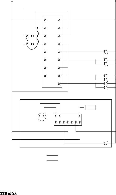
Figure 7
Typical WD25MR/FR, WD50MR/FR Electrical Schematic, Drawing 2
4 |
2 |
10 |
|
|
|
|
|
|
|
|
|
1PLC |
|
4 |
|
4 |
L1 |
L2 |
2 |
|
|
|
|||
|
|
9 |
COM |
+24V |
9 |
|
|
|
|
||
10 |
1M |
11 |
000 |
-24V |
10 |
|
|
|
|||
10 |
1CR |
12 |
001 |
COM |
4 |
|
|
|
|||
|
18GA BLUE 24VDC |
|
002 |
0 |
13 |
|
|
|
|
||
|
INPUT WIRING |
|
|
|
|
2
G |
3LT |
2 |
|
|
|
|
003 |
1 |
14 |
|
|
|
|
|
2CR |
|
2 |
|
|
|
|
|
|
|
|
|
|
|||
|
|
|
|
|
|
|
|
|
|
|
|
|
|
|
|
|
|
|
|
|
|
14 |
G |
4LT |
2 |
|
|
004 |
COM |
|
|
|
|
|
|
|
|
|
|
|
4 |
|
|
|
|
|
|
|
|
||
|
|
|
|
|
|
|
|
|
|
|
|
|
|
|
005 |
2 |
15 |
|
|
|
|
|
2C |
|
2 |
|
|
|
|
|
|
|
|
|
|
|||
|
|
|
|
|
|
|
|
|
|
|
|
|
|
|
|
|
|
|
|
|
|
15 |
G |
5LT |
2 |
|
|
|
3 |
|
|
|
|
|
|
|
|
|
|
|
|
16 |
|
|
|
|
|
3C |
|
2 |
|
|
|
|
|
|
|
|
|
|
|
|||
|
|
|
|
|
|
|
|
|
|
|
|
|
|
|
|
|
|
|
|
|
|
16 |
G |
6LT |
2 |
|
|
|
|
|
|
|
|
|
|
|
|
|
4 |
|
|
|
|
|
|
|
|
|
|
|
|
|
|
OPTIONAL DEW POINT CONTROL |
|
|
|
|
|
|
||||
|
|
|
|
|
|
|
|
|
1DPT |
|
|
|
|
|
RED |
|
BLK |
|
|
|
|
|
|
|
|
DEW POINT |
- |
+ |
|
|
|
1DPB |
|
|
|
|
|
|
METER |
|
|
|
|
|
|
|
|
|
|
||
|
|
1 |
2 |
3 |
4 |
5 |
6 |
|
7 |
|
|
|
|
|
1DMTR |
|
|
|
|
|
|
|
|
|
|
|
|
|
|
17 |
|
4 |
2 |
|
4 |
|
|
|
4 |
|
|
|
|
|
|
|
|
|
|
|
2 |
4 |
|
|
|
|
|
|
|
4 |
A0547615 |
|
|
|
|
|
|
|
17 |
|
|
|
|
|
7LT |
2 |
|
|
|
|
|
|
|
|
|
|
G |
|||
|
|
|
|
|
|
|
|
|
|
|
|
|
LEGEND:
OPTIONAL COMPONENTS
COMPONENTS LOCATED EXTERNALLY
OF CONTROL ENCLOSURE
"LEFT BED IN REGEN"
BED SHIFT RELAY
"RIGHT BED IN REGEN"
LEFT BED CONTACTOR
"LEFT BED HEATER" ON
RIGHT BED CONTACTOR
"RIGHT BED HEATER" ON
DEW POINT CONTROL BOARD
"HIGH DEW POINT"
Refer to your Customer Information Packet on actual drawings for your specific dryer.
WDMR and WDFR Series Dehumidifying Dryers |
Page 21 |

Figure 8
Typical Control Subpanel Layout
1DBLK
GRD
omron
SYSMAC mini
PLC
1T
1DPT
1DPB
1CR 2CR
1M |
2C |
3C |
1FU |
|
1C
A0547616
10L
Refer to your Customer Information Packet on actual drawings for your specific dryer.
Page 22 |
WDMR and WDFR Series Dehumidifying Dryers |

3-5 Making Dryer/Drying Hopper Process Air
Connections
Floor Mount Models (FR)
Use high-temperature flexible dryer hose or rigid tubing to connect the dryer to the drying hopper.
Keep the delivery hose to the drying hopper as short as possible to minimize heat loss. We strongly recommend insulated hose for maximum energy savings.
Do not use insulated hose on the return from the drying hopper.
Do not shorten the return hose. The return air to the blower must be 150°F (66ºC) or below. If the return air temperature is not below this point, you should purchase and install the optional aftercooler to remove excessive heat. Consult AEC, Inc. for more information.
Aftercooler considerations also apply to machine-mount models. Make sure that hoses are not kinked or collapsed.
Drying hopper air inlet and outlet locations vary, but always connect hoses so the dry process air from the dryer enters the bottom of the drying hopper and flows out the top to return to the dryer inlet.
3-6 Drying Hopper Air Trap Considerations
AEC/Whitlock’s exclusive air trap assembly on the top of the drying hopper prevents ambient air from contaminating the material being dried.
Keep the material level at the mid point of the air trap for maximum efficiency.
Use a hopper loader or vacuum conveying system to maintain the proper material level.
3-7 Installing the Optional Aftercooler
Air-cooled WD10MR/FR and WD25MR/FR models use an air-to-air heat exchanger as an aftercooler. No cooling water is required for this design. Return air from the hopper passes through the air filter to trap fines and dust before entering the heat exchanger.
WDMR and WDFR Series Dehumidifying Dryers |
Page 23 |

Installing Air Hose
Water-Cooled Aftercooler for WD50MR Dryers
Air is routed from the bottom of the aftercooler up through the top.
•Connect the hot incoming air hose from the drying hopper to the bottom 2” (about 51 mm) tube stub with a hose clamp.
•Connect the cooled outgoing air hose to the 2” (about 51 mm) tube at the top of the cooler. Run this hose to the inlet of the process air filter on top of the dryer.
Figure 9
Aftercooler Design Specifications
Entering air temp. |
Leaving air temp. |
Entering water temp. |
Leaving water temp. |
Initial flow rate |
|||||
ºF |
ºC |
ºF |
ºC |
ºF |
ºC |
ºF |
ºC |
gpm |
lpm |
250ºF |
121ºC |
130ºF |
54ºC |
80ºF |
27ºC |
85ºF |
29ºC |
3 gpm |
11 lpm |
Installing Water Lines
WD50MR/FR Models
•Use the ½” (about 13 mm) brass pipe nipples for water line connections. Connect the entering water line to the pipe nipple, located in the center of the cover.
•Make sure you grip the nipple tightly when attaching a fitting. Doing so prevents damage to the soft copper coils. You should make connections with flexible hose to allow removing the coil assembly for cleaning.
•The aftercooler is designed to utilize either tower or city water as warm as 85ºF (29ºC). Recommended flow rate is one to three (1 to 3) gallons per minute (4 to 11 liters per minute).
Important!
You must use an aftercooler on WD50MR/FR models to operate at process supply temperatures of 180ºF (82ºC) or below.
You are required to use a chilled water supply of 50ºF (10ºC) to pre-condition the dryer return air so the dryer can properly achieve low dew points and process temperatures.
If an aftercooler is used with a drying system, AEC highly recommends that a high temperature return air filter element is substituted for the standard element. Order Part No. A0538636 from the AEC/Whitlock Parts Department.
Page 24 |
WDMR and WDFR Series Dehumidifying Dryers |

4 |
Level 1 Controllers |
|
|
Your dryer comes with the standard Level 1 control panel or the optional Level 2 control panel. This chapter discusses the features of each, starting with Level 1 features. Level 2 features begin in Chapter 5 on Page 33, with a graphic of the Level 2 control panel in Figure 13 on Page 34.
4-1 Level 1 Control Panel Indicator Lights
Control Power On
The Control Power On indicator lights when the dryer control circuit energizes.
Process Heater On
The Process Heater On indicator lights when the process air heater energizes.
High Process Air Temperature Alarm
The High Process Air Temperature alarm indicator lights when the temperature at the process air thermocouple is above the set high alarm value. When the indicator lights, the alarm relay energizes and all the heaters turn off while the blower remains on to cool the dryer.
•The alarm mode and value are factory-set to track 25° above the process set point. The alarm value is a deviation above the process set point, and the user can adjust it.
•When the temperature at the process thermocouple returns to within the acceptable range, the alarm output de-energizes and all the heaters turn on again automatically.
•You can alter the alarm range. See Section 6-5 on Page 43 for more information.
Regen Heater On
The Regen Heater On indicator lights when the left or right bed regeneration heater is on.
Left Bed Regenerating and Right Bed Regenerating
The lit Left Bed Regenerating or Right Bed Regenerating LED indicates the bed currently being regenerated (off-line).
High Dew Point Alarm (optional)
The High Dew Point alarm indicator lights when the process air delivery dew point exceeds the dew point alarm point, factory set at -10°F (-23ºC).
WDMR and WDFR Series Dehumidifying Dryers |
Page 25 |
Loading...