


WD 350 through WD3000 Dehumidifying Dryers
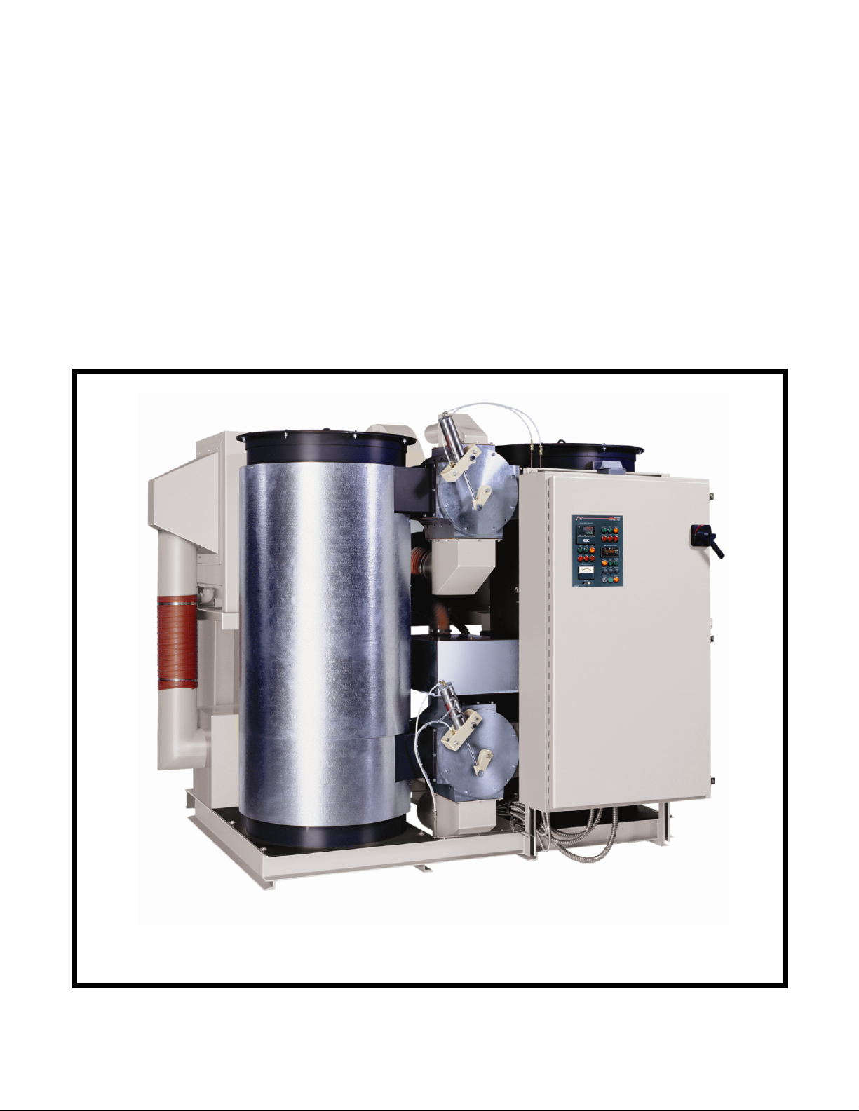
OPERATION AND INSTALLATION MANUAL
WD/SDA/CDA SERIES
350 - 2100 CFM
LARGE DEHUMIDIFYING DRYERS
IMPORTANT: PLEASE READ CAREFULLY BEFORE ATTEMPTING TO INSTALL
OR OPERATE EQUIPMENT
Bulletin No: DH1-655 Part No: 882.00225.00 Effective: 11-01-05

Please note that our address and phone information has changed.
Please reference this page for updated contact information.
These manuals are obsolete and are provided only for their technical information, data and capacities.
Portions of these manuals detailing procedures or precautions in the operation, inspection, maintenance
and repair of the products may be inadequate, inaccurate, and/or incomplete and shouldn’t be relied
upon. Please contact the ACS Group for more current information about these manuals and their
warnings and precautions.
Parts and Service Department
The ACS Customer Service Group will provide your company with genuine OEM quality parts manufactured to engineering
design specifications, which will maximize your equipment’s performance and efficiency. To assist in expediting your phone
or fax order, please have the model and serial number of your unit when you contact us. A customer replacement parts list
is included in this manual for your convenience. ACS welcomes inquiries on all your parts needs and is dedicated to
providing excellent customer service.
For immediate assistance, please contact:
• North, Central and South America, 8am – 5pm CST +1 (800) 483-3919 for drying, conveying, heating and cooling
and automation. For size reduction: +1 (800) 229-2919.
North America, emergencies after 5pm CST (847) 439-5855
North America email: acsuscanadacustserv@corpemail.com
• Mexico, Central & South America
Email: acslatinamericacustserv@corpemail.com
• Europe, Middle East & Africa +48 22 390 9720
Email: acseuropecustserv@corpemail.com
• India +91 21 35329112
Email: acsindiacustserv@corpemail.com
• Asia/Australia +86 512 8717 1919
Email: acsasiacustserv@corpemail.com
Sales and Contracting Department
Our products are sold by a worldwide network of independent sales representatives. Contact our Sales Department for the
name of the sales representative nearest you.
Let us install your system. The Contract Department offers any or all of these services: project planning; system packages
including drawings; equipment, labor, and construction materials; and union or non-union installations.
For assistance with your sales or system contracting needs please Call:
North, Central and South America +1 (262) 641-8600 or +1 (847) 273-7700 Monday–Friday, 8am–5pm CST
Europe/Middle East/Africa +48 22 390 9720
India +91 21 35329112
Asia/Australia +86 512 8717 1919
Facilities:
ACS offers facilities around the world to service you no matter where you are located. For more information, please visit us at
www.acscorporate.com
United States:
ACS Schaumburg – Corporate Offices
1100 E. Woodfield Road
Suite 588
Schaumburg, IL 60173
Phone: + 1 847 273 7700
Fax: + 1 847 273 7804
ACS New Berlin – Manufacturing Facility
2900 S. 160th Street
New Berlin, WI 53151
Phone : +1 262 641 8600
Fax: + 1 262 641 8653
Asia/Australia:
ACS Suzhou
109 Xingpu Road SIP
Suzhou, China 215126
Phone: + 86 8717 1919
Fax: +86 512 8717 1916
Europe/Middle East/Africa:
ACS Warsaw
Ul. Działkowa 115
02-234 Warszawa
Phone: + 48 22 390 9720
Fax: +48 22 390 9724
India
ACS India
Gat No. 191/1, Sandbhor Complex
Mhalunge, Chakan, Tal Khed,
Dist. Pune 410501, India
Phone: +91 21 35329112
Fax: + 91 20 40147576

Write Down Your Serial Numbers Here For Future Reference:
_________________________ _________________________
_________________________ _________________________
_________________________ _________________________
We are committed to a continuing program of product improvement.
Specifications, appearance, and dimensions described in this manual are subject to change without notice.
DCN No. ____________
© Copyright 2005
All rights reserved.
Bulletin Number ii

Shipping Info
Unpacking and Inspection
You should inspect your dryer for possible shipping damage.
Thoroughly check the equipment for any damage that might have occurred in transit, such as
broken or loose wiring and components, loose hardware and mounting screws, etc.
In the Event of Shipping Damage
According to the contract terms and conditions of the Carrier, the responsibility of the
Shipper ends at the time and place of shipment.
Notify the transportation company’s local agent if you discover damage.
Hold the damaged goods and packing material for the examining agent’s inspection. Do not
return any goods before the transportation company’s inspection and authorization.
File a claim with the transportation company. Substantiate the claim by referring to the
agent’s report. A certified copy of our invoice is available upon request. The original Bill of
Lading is attached to our original invoice. If the shipment was prepaid, write us for a
receipted transportation bill.
Advise customer service regarding your wish for assistance and to obtain an RMA (return
material authorization) number.
If the Shipment is Not Complete
Check the packing list as back-ordered items are noted on it. You should have:
; Dehumidifying Dryer
; Bill of lading
; Packing list
; Operating and Installation packet
; Electrical schematic and panel layout drawings
; Component instruction manuals
Re-inspect the container and packing material to see if you missed any smaller items during
unpacking.
If the Shipment is Not Correct
If the shipment is not what you ordered, contact the shipping department immediately. For
shipments in the United States and Canada, call 1 (800) 233-4819; for all other countries, call
our international desk at (630) 475-7491. Have the order number and item number available.
Hold the items until you receive shipping instructions.
Returns
Do not return any damaged or incorrect items until you receive shipping instructions from the
shipping department.
Bulletin Number iii

Table of Contents
CHAPTER 1: SAFETY................................................................ 6
1-1 How to Use This Manual ............................................................................................. 6
Safety Symbols Used in this Manual.....................................................................6
1-2 Safety Tag Information ................................................................................................ 7
Dryer Safety Tags .................................................................................................7
1-3 Warnings and Precautions .......................................................................................... 8
1-4 Responsibility .............................................................................................................. 9
General Responsibility ..........................................................................................9
Operator Responsibility .........................................................................................9
Maintenance Responsibility................................................................................. 10
Reporting a Safety Defect ................................................................................... 11
1-5 Responsibility ............................................................................................................ 11
CHAPTER 2: FUNCTIONAL DESCRIPTION........................... 12
2-1 Models Covered in This Manual................................................................................12
2-2 General Description................................................................................................... 12
2-3 Typical Features and Components ...........................................................................12
2-4 Optional Features......................................................................................................12
2-5 The Closed Loop Drying System............................................................................... 13
2-6 What is Desiccant?.................................................................................................... 13
2-7 The Process/Regeneration Cycle.............................................................................. 13
2-8 Specifying a Drying System ......................................................................................14
CHAPTER 3: INSTALLATION.................................................. 17
3-1 Work Rules................................................................................................................17
3-2 Electrical Connections............................................................................................... 17
3-3 Check For Proper Blower Rotation............................................................................ 17
3-4 Dryer/Drying Hopper Process Air Hose Connection .................................................17
3-5 Aftercooler Cooling Water Connection ...................................................................... 18
3-6 Drying Hopper Air Trap .............................................................................................18
CHAPTER 4: CONTROL PANEL ............................................. 20
4-1 Control Panel Indicator Lights ................................................................................... 20
4-2 Switches and Meters ................................................................................................. 22
4-3 PLC Control...............................................................................................................23
4-4 Process Air Temperature Controller..........................................................................23
4-5 Temperature Controller LED Indicators..................................................................... 25
4-6 Temperature Controller Keys – (See Figure 5 in Section 3-6) .................................. 26
4-7 Optional Communications Protocols ......................................................................... 26
CHAPTER 5: STARTUP, SHUTDOWN & OPERATION.......... 27
5-1 Pre-Startup Checks ................................................................................................... 27
5-2 Startup.......................................................................................................................27
5-3 Shutdown ..................................................................................................................28
5-4 Setting the Process Air Temperature ........................................................................ 28
Bulletin Number iv

5-5
Setting the High and Low Temperature Alarms ........................................................28
5-6 Temperature Controller Autotune Procedure ............................................................ 29
5-7 Temperature Controller Internal Switches.................................................................29
5-8 Temperature Controller Anti-Tamper Lockout Switch ............................................... 29
5-9 Changing the Display from Fahrenheit to Centigrade ............................................... 30
5-10 Setting the Dewpoint Extend Shift Point.................................................................... 30
5-11 Regeneration Monitoring System Signal Processor.................................................. 31
5-12 Auxiliary Process Safety System (Optional)..............................................................32
5-13 Seven Day Timer (Optional)...................................................................................... 32
CHAPTER 6: MAINTENANCE ................................................. 35
6-1 Servicing the Process Air Filters (Models 350-700) .................................................. 35
6-2 Filter Cleaning/Replacement ..................................................................................... 35
6-3 Servicing the Process Air Filters (Models 850 through 2100) ................................... 36
6-4 Servicing the Regeneration Filter .............................................................................. 37
6-5 Dirty Filter Alarm Calibration .....................................................................................37
6-6 Dewpoint Control System Service............................................................................. 38
6-7 Symptoms of Worn Out Desiccant ............................................................................ 38
6-8 Desiccant Replacement Procedure...........................................................................39
6-9 Process Heater Replacement Procedure.................................................................. 40
6-10 Regeneration Heater Replacement Procedure ......................................................... 41
6-11 Restoring a Temperature Controller to the Factory Setup ........................................42
6-12 Regeneration Monitor Advanced Programming ........................................................ 48
CHAPTER 7: TROUBLESHOOTING ....................................... 52
CHAPTER 8: APPENDIX.......................................................... 55
8-1 Customer Satisfaction Warranty Program................................................................. 55
8-2 Technical Assistance................................................................................................. 58
Parts Department ................................................................................................ 58
Service Department............................................................................................. 58
Sales Department................................................................................................ 58
Contract Department ...........................................................................................58
Bulletin Number v

Chapter 1: Safety
1-1 How to Use This Manual
Use this manual as a guide and reference for installing, operating, and maintaining your
dehumidifying dryer. The purpose is to assist you in applying efficient, proven techniques
that enhance equipment productivity.
This manual covers only light corrective maintenance. No other maintenance should be
undertaken without first contacting a service engineer.
The Functional Description section outlines models covered, standard features, and safety
features. Additional sections within the manual provide instructions for installation, preoperational procedures, operation, preventive maintenance, and corrective maintenance.
The Installation chapter includes required data for receiving, unpacking, inspecting, and setup
of the dehumidifying dryer. We can also provide the assistance of a factory-trained technician
to help train your operator(s) for a nominal charge. This section includes instructions, checks,
and adjustments that should be followed before commencing with operation of the
dehumidifying dryer. These instructions are intended to supplement standard shop
procedures performed at shift, daily, and weekly intervals.
The Operation chapter includes a description of electrical and mechanical controls, in
addition to information for operating the dryer safely and efficiently.
The Maintenance chapter is intended to serve as a source of detailed assembly and
disassembly instructions for those areas of the equipment requiring service. Preventive
maintenance sections are included to ensure that your dehumidifying dryer provides
excellent, long service.
The Troubleshooting chapter serves as a guide for identification of most common problems.
Potential problems are listed, along with possible causes and related solutions.
The Appendix contains technical specifications, drawings, schematics, parts lists, and
available options. A spare parts list with part numbers specific to your machine is provided
with your shipping paperwork package. Refer to this section for a listing of spare parts for
purchase. Have your serial number and model number ready when ordering.
Safety Symbols Used in this Manual
The following safety alert symbols are used to alert you to potential personal injury hazards.
Obey all safety messages that follow these symbols to avoid possible injury or death.
DANGER! DANGER indicates an imminently hazardous situation that, if not avoided,
will result in death or serious injury.
WARNING! WARNING indicates a potentially hazardous situation or practice that, if
not avoided, could result in death or serious injury.
Caution! CAUTION indicates a potentially hazardous situation or practice that, if
not avoided, may result in minor or moderate injury or in property damage.
350-2100 cfm Dryers Chapter 1: Safety 6 of 58

1-2 Safety Tag Information
Dryer Safety Tags
Hot! Read Operation
and Installation
Manual
High Voltage Earth Ground
Inside Enclosure
PE Protected Earth
Lifting Point Ground
350-2100 cfm Dryers Chapter 1: Safety 7 of 58

1-3 Warnings and Precautions
Our equipment is designed to provide safe and reliable operation when installed and operated
within design specifications, following national and local safety codes. This may include, but
is not limited to OSHA, NEC, CSA, SPI, and any other local, national and international
regulations.
To avoid possible personal injury or equipment damage when installing, operating, or
maintaining this equipment, use good judgment and follow these safe practices:
; Read and follow these operation and installation instructions when installing,
operating, and maintaining this equipment. If these instructions become
damaged or unreadable, additional copies are available from the manufacturer.
; Follow all SAFETY CODES.
; Wear SAFETY GLASSES and WORK GLOVES.
; Work only with approved tools and devices.
; Disconnect and/or lock out power before servicing or maintaining the equipment.
; Use care when LOADING, UNLOADING, RIGGING, or MOVING this
equipment.
; Operate this equipment within design specifications.
; OPEN, TAG, and LOCK ALL DISCONNECTS before working on equipment.
You should remove the fuses and carry them with you.
; Make sure the equipment and components are properly GROUNDED before you
switch on power.
; Use EXTREME CAUTION when working with dryer. HIGH HEAT can be
dangerous. Keep body parts, tools, clothing, and debris away from dryer.
; When welding or brazing in or around this equipment, make sure VENTILATION is
ADEQUATE. PROTECT adjacent materials from flame or sparks by shielding with
sheet metal. An approved FIRE EXTINGUISHER should be close at hand and
ready for use if needed.
; Do not restore power until you remove all tools, test equipment, etc., and the
equipment and related components are fully reassembled.
; Only PROPERLY TRAINED personnel familiar with the information in this
manual should work on this equipment.
We have long recognized the importance of safety and have designed and manufactured our
equipment with operator safety as a prime consideration. We expect you, as a user, to abide
by the foregoing recommendations in order to make operator safety a reality.
350-2100 cfm Dryers Chapter 1: Safety 8 of 58

1-4 Responsibility
These machines are constructed for maximum operator safety when used under standard
operating conditions and when recommended instructions are followed in the maintenance
and operation of the machine.
All personnel engaged in the use of the machine should become familiar with its operation as
described in this manual.
Proper operation of the machine promotes safety for the operator and all workers in its
vicinity.
Each individual must take responsibility for observing the prescribed safety rules as outlined.
All warning and danger signs must be observed and obeyed. All actual or potential danger
areas must be reported to your immediate supervisor.
General Responsibility
No matter who you are, safety is important. Owners, operators and maintenance personnel
must realize that every day, safety is a vital part of their jobs.
If your main concern is loss of productivity, remember that production is always affected in a
negative way following an accident. The following are some of the ways that accidents can
affect your production:
• Loss of a skilled operator (temporarily or permanently)
• Breakdown of shop morale
• Costly damage to equipment
• Downtime
An effective safety program is responsible and economically sound.
Organize a safety committee or group, and hold regular meetings. Promote this group from
the management level. Through this group, the safety program can be continually reviewed,
maintained, and improved. Keep minutes or a record of the meetings.
Hold daily equipment inspections in addition to regular maintenance checks. You will keep
your equipment safe for production and exhibit your commitment to safety.
Please read and use this manual as a guide to equipment safety. This manual contains safety
warnings throughout, specific to each function and point of operation.
Operator Responsibility
The operator’s responsibility does not end with efficient production. The operator usually has
the most daily contact with the equipment and intimately knows its capabilities and
limitations.
Plant and personnel safety is sometimes forgotten in the desire to meet incentive rates, or
through a casual attitude toward machinery formed over a period of months or years. Your
employer probably has established a set of safety rules in your workplace. Those rules, this
manual, or any other safety information will not keep you from being injured while operating
your equipment.
350-2100 cfm Dryers Chapter 1: Safety 9 of 58

Learn and always use safe operation. Cooperate with co-workers to promote safe practices.
Immediately report any potentially dangerous situation to your supervisor or appropriate
person.
REMEMBER:
• NEVER place your hands or any part of your body in any dangerous location.
• NEVER operate, service, or adjust the dryer without appropriate training and first
reading and understanding this manual.
• NEVER try to pull material out of the dryer with your hands while it is running!
• Before you start the dryer check the following:
• Remove all tools from the dryer;
• Be sure no objects (tools, nuts, bolts, clamps, bars) are laying in the
hopper area;
• If your dryer has been inoperative or unattended, check all settings before starting the
unit.
• At the beginning of your shift and after breaks, verify that the controls and other
auxiliary equipment are functioning properly.
• Keep all safety guards in place and in good repair. NEVER attempt to bypass, modify,
or remove safety guards. Such alteration is not only unsafe, but will void the warranty
on your equipment.
• When changing control settings to perform a different mode of operation, be sure
selector switches are correctly positioned. Locking selector switches should only be
adjusted by authorized personnel and the keys removed after setting.
• Report the following occurrences IMMEDIATELY:
• unsafe operation or condition
• unusual dryer action
• leakage
• improper maintenance
• NEVER stand or sit where you could slip or stumble into the dryer
while working on it.
• DO NOT wear loose clothing or jewelry, which can be caught while working on a
dryer. In addition, cover or tie back long hair.
• Clean the dryer and surrounding area DAILY, and inspect the machine for loose,
missing or broken parts.
• Shut off power to the dryer when it is not in use. Turn the switch to the OFF position,
or unplug it from the power source.
Maintenance Responsibility
Proper maintenance is essential to safety. If you are a maintenance worker, you must make
safety a priority to effectively repair and maintain equipment.
350-2100 cfm Dryers Chapter 1: Safety 10 of 58

Before removing, adjusting, or replacing parts on a machine, remember to turn off all electric
supplies and all accessory equipment at the machine, and disconnect and lockout electrical
power. Attach warning tags to the disconnect switch.
When you need to perform maintenance or repair work on a dryer above floor level, use a
solid platform or a hydraulic elevator. If there is a permanently installed catwalk on your
dryer, use it. The work platform should have secure footing and a place for tools and parts.
DO NOT climb on dryers, machines, or work from ladders.
If you need to repair a large component, use appropriate handling equipment. Before you use
handling equipment (portable “A” frames, electric boom trucks, fork trucks, overhead cranes)
be sure the load does not exceed the capacity of the handling equipment or cause it to become
unstable.
Carefully test the condition of lifting cables, chains, ropes, slings, and hooks before using
them to lift a load.
Be sure that all non-current carrying parts are correctly connected to earth ground with an
electrical conductor that complies with current codes. Install in accordance with national and
local codes.
When you have completed the repair or maintenance procedure, check your work and remove
your tools, rigging, and handling equipment.
Do not restore power to the dryer until all persons are clear of the area. DO NOT start and
run the dryer until you are sure all parts are functioning correctly.
BEFORE you turn the dryer over to the operator for production, verify all dryer enclosure
panels, guards and safety devices are in place and functioning properly.
Reporting a Safety Defect
If you believe that your equipment has a defect that could cause injury, you should
immediately discontinue its use and inform the manufacturer.
The principle factors that can result in injury are failure to follow proper operating procedures
(i.e. lockout/tagout), or failure to maintain a clean and safe working environment.
1-5 Responsibility
These machines are constructed for maximum operator safety when used under standard
operating conditions and when recommended instructions are followed in the maintenance
and operation of the machine.
All personnel engaged in the use of the machine should become familiar with its operation as
described in this manual.
Proper operation of the machine promotes safety for the operator and all workers in its
vicinity.
Becoming familiar with materials, inspection, speed limitations, screens, and guard
maintenance and total user responsibility will assist you in learning potential areas in need of
observation for danger.
Each individual must take responsibility for observing the prescribed safety rules as outlined.
All caution, warning and danger signs must be observed and obeyed. All actual or potential
danger areas must be reported to your immediate supervisor.
350-2100 cfm Dryers Chapter 1: Safety 11 of 58

Chapter 2: Functional Description
2-1 Models Covered in This Manual
This manual provides operation, installation, and maintenance instructions for
WD/SDA/CDA 350, 425, 500, 600, 700, 850, 1000, 1250, 1500, 1800, and 2100 cfm large
dehumidifying dryers in both standard 300˚ F and 400˚ F high temperature “-RT” models.
Model numbers are listed on the serial tag. Make sure you know the model and serial number
of your equipment before contacting the manufacturer for parts or service.
2-2 General Description
Dehumidifying Dryers are designed to generate heated, dehumidified air at carefully
controlled temperatures for use in closed-loop plastic drying systems. Drying systems are
sized to meet the specific requirements stated by the purchaser at the time of purchase.
Moisture removal from hygroscopic (moisture attracting) plastic pellets is an essential step in
the manufacture of high-quality plastic products.
ACS dryers are used by the plastics industry to generate very low dewpoint air that is heated
to a controlled temperature for drying plastic pellets and regrind.
2-3 Typical Features and Components
1. Branch Fusing provides additional protection to the operator and the components on
the dryer's sub-panel.
2. Dewpoint Monitor indicates dryer efficiency
2-4 Optional Features
Options can tailor an ACS dryer to meet the exact requirements of the drying task being
performed.
• Dirty filter indicator to advise the operator when it's time to clean the filters.
• Water-cooled aftercooler for closed loop regeneration air cooling
• SMART PLC to combine PLC features and a "Plain English" interface. This option is
fully described in its own manual.
• Heater Burnout Indicator to monitor the heater(s) amp draw.
• Compressed air filter cleaning to lower maintenance on regrind/dusty material drying
processes.
• Auxiliary high temperature safety system to cut high voltage to the blowers and
heaters in the event of run-away process heaters.
• Seven day timer to allow programmable dryer start up.
• Communications to meet customer needs.
• Drying Hoppers come in many sizes and mounting configurations.
• Conveying Equipment to transport material to and from the drying system.
• Insulated Process Air Hose to minimize heat loss between the dryer and the drying
hopper.
350-2100 cfm Dryers Chapter 2: Functional Description 12 of 58
2-5 The Closed Loop Drying System
ACS dryers force hot, dry air through the resin in the drying hopper, where the air picks up
moisture from the material and is drawn back to the dryer.
In the dryer, moisture is stripped from the air by a desiccant bed. The dried process air is then
re-heated and delivered back into the drying hopper to dry material again.
This system is a "closed loop", because ambient (outside) air is never introduced into the
process air. The closed loop system is used by ACS because the process air is typically much
drier than ambient air, even after carrying moisture out of the plastic resin. Recycling process
air maintains drying efficiency at a consistently high level.
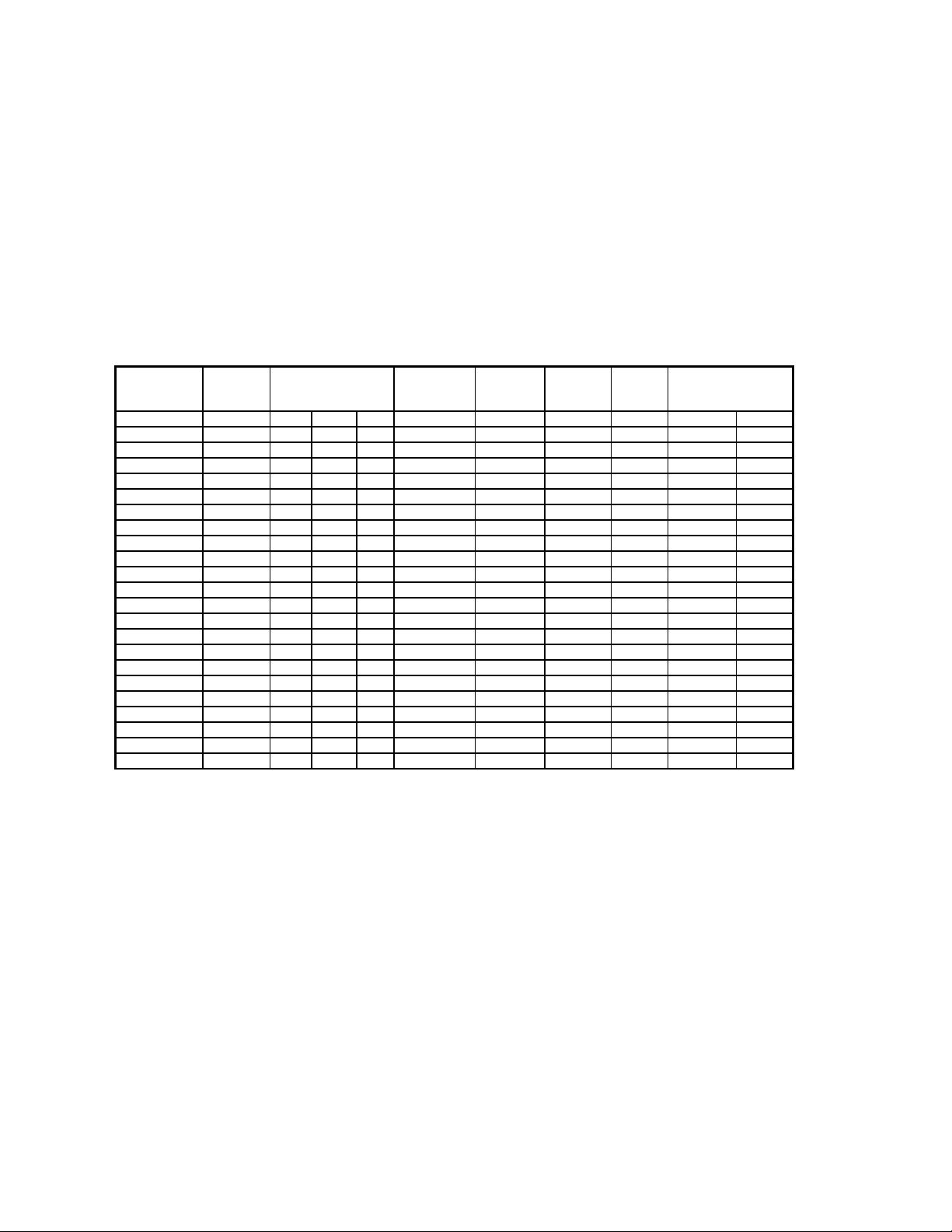
Figure 1: WD/SDA/CDA 350-2100 Dryer Specifications
Model
Number
460-3-60 L W H I.D. Lbs. Hp. Hp. Large Small
350 56 56 73 4 1000 5 ½ 30 76
350-RT 56 56 73 4 1000 5 ½ 30 76
425 61 52 82 5 1100 7½ ½ 30 90
425-RT 61 52 82 5 1100 7½ ½ 30 90
500 63 66 94 5 1200 7½ ¾ 40 100
500-RT 63 66 94 5 1200 7½ ¾ 40 100
600 58 56 88 6 1450 10 ¾ 40 120
600-RT 58 56 88 6 1450 10 ¾ 40 120
700 59 66 93 6 1600 10 ¾ 40 135
700-RT 59 66 93 6 1600 10 ¾ 40 135
850 103 88 84 90 8 3 ¾ 120 120
850-RT 141 88 84 90 8 3 ¾ 120 120
1000 113 88 84 90 8 7½ ¾ 120 130
1000-RT 146 88 84 90 8 7½ ¾ 120 130
1250 138 88 84 90 8 7½ ¾ 120 180
1250-RT 194 88 84 90 8 7½ ¾ 120 180
1500 156 94 100 90 8 7½ ¾ 120 240
1500-RT 213 94 100 90 8 7½ ¾ 120 240
1800 179 94 100 90 8 10 ¾ 120 310
1800-RT 235 94 100 90 8 10 ¾ 120 310
2100 203 94 100 98 10 15 ¾ 120 360
2100-RT 278 94 100 98 10 15 ¾ 120 360
Amp
Draw
Dimensions
(Inches)
Hose
Connection
(Inches)
Shipping
Weight
Process
Blower
Regen
Blower
Desiccant
Lbs./Bed
2-6 What is Desiccant?
Desiccant is a material which attracts and holds (absorbs) water from the air. The desiccant
ACS dryers use is a synthetic crystalline metal aluminosilicate that is blended with a clay
binder and formed into beads.
Absorbed water is driven from saturated desiccant by heating it to a high temperature
(reducing the desiccant's capacity to hold water) and forcing air through it. This moisture
removal process is called "regeneration".
2-7 The Process/Regeneration Cycle
ACS dryers have two desiccant beds. While one bed is on-line in the process air loop, the
other is off-line being regenerated.
350-2100 cfm Dryers Chapter 2: Functional Description 13 of 58
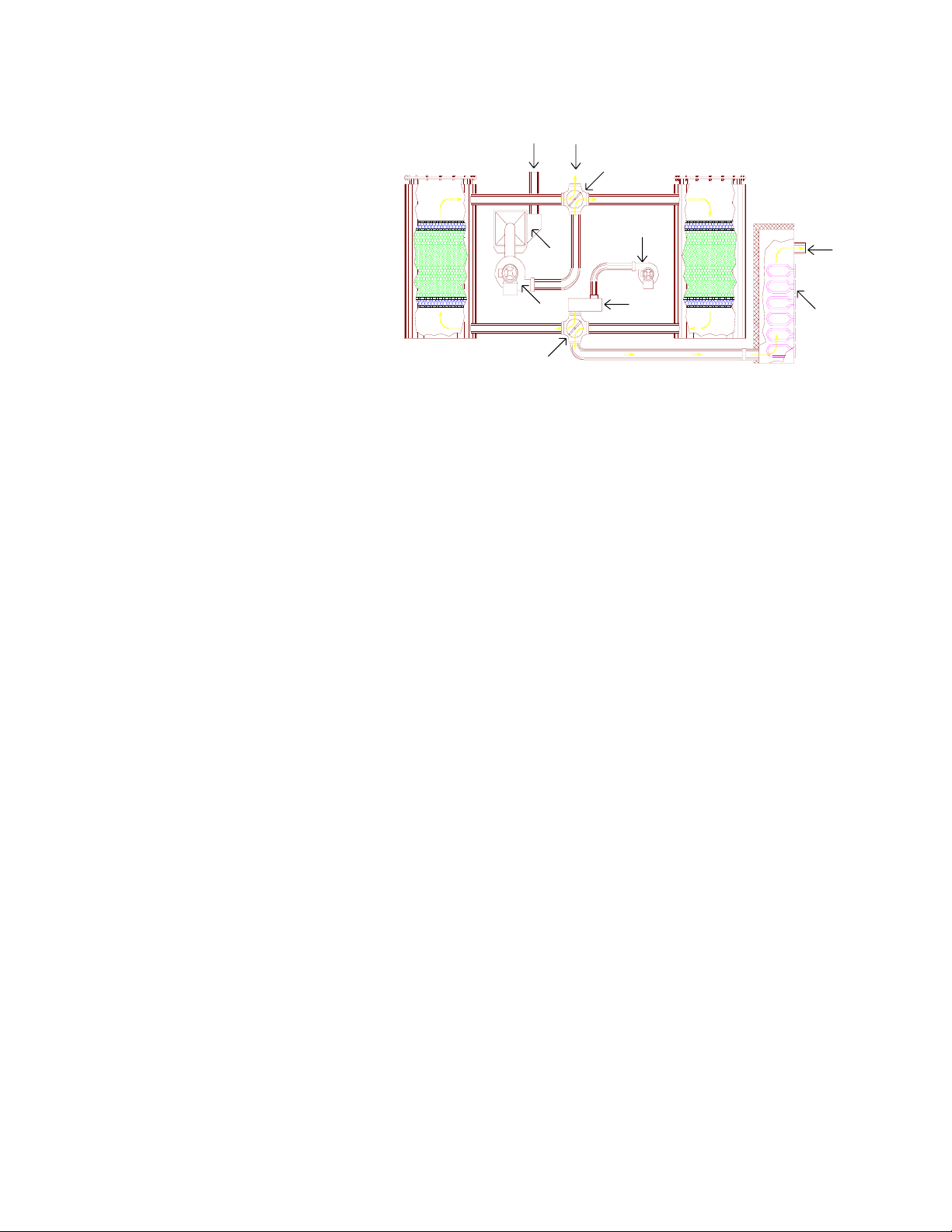
When a desiccant bed is online, it absorbs moisture
from the process air. In
Process Return Air
From Drying Hopper
Bleed
Upper
Control
Valve
time, the bed becomes
saturated with moisture and
needs to be regenerated.
The dryer automatically
Desiccant
Bed
Process
Filter
Assembly
Regeneration
Blower
Desiccant
Bed
Process
Delivery
Air
redirects the process
airflow to the second bed,
and starts the regeneration
cycle on the first bed.
During regeneration, air is
heated to approximately
550°F and forced through
Process
Blower
Lower
Control
Valve
Figure Two:
Airflow Diagram
Regeneration
Heater
Process
Heaters
the desiccant bed. The moisture driven off the bed is bled to the atmosphere.
If the temperature of the air bled to atmosphere (bleed temperature) is measured, a rise can be
observed after a period of time. This condition, called "bed breakthrough" indicates that the
bed is dry. At bed breakthrough, the bleed air temperature peaks between 350°F and 400°F.
Dryer models 350 through 2100 dryers are equipped with the Dewpoint Extend feature. The
regeneration heaters turn off automatically on bed breakthrough for additional energy
savings. A 550°F regeneration temperature will dry the desiccant beds sufficiently to produce
process air dewpoint of -40°F. In a properly sized system, this ultra-low humidity level will
be more than adequate to dry plastics to as little as .003% moisture.
2-8 Specifying a Drying System
There were many variables considered in the selection of your drying system, including: type
of materials, residence time, throughput of the extruder or injection molding machine,
ambient air moisture and temperature, and the altitude at the processing site. Should your
operating environment change, the manufacturer can advise you on necessary equipment and
process time and temperature modifications.
350-2100 cfm Dryers Chapter 2: Functional Description 14 of 58
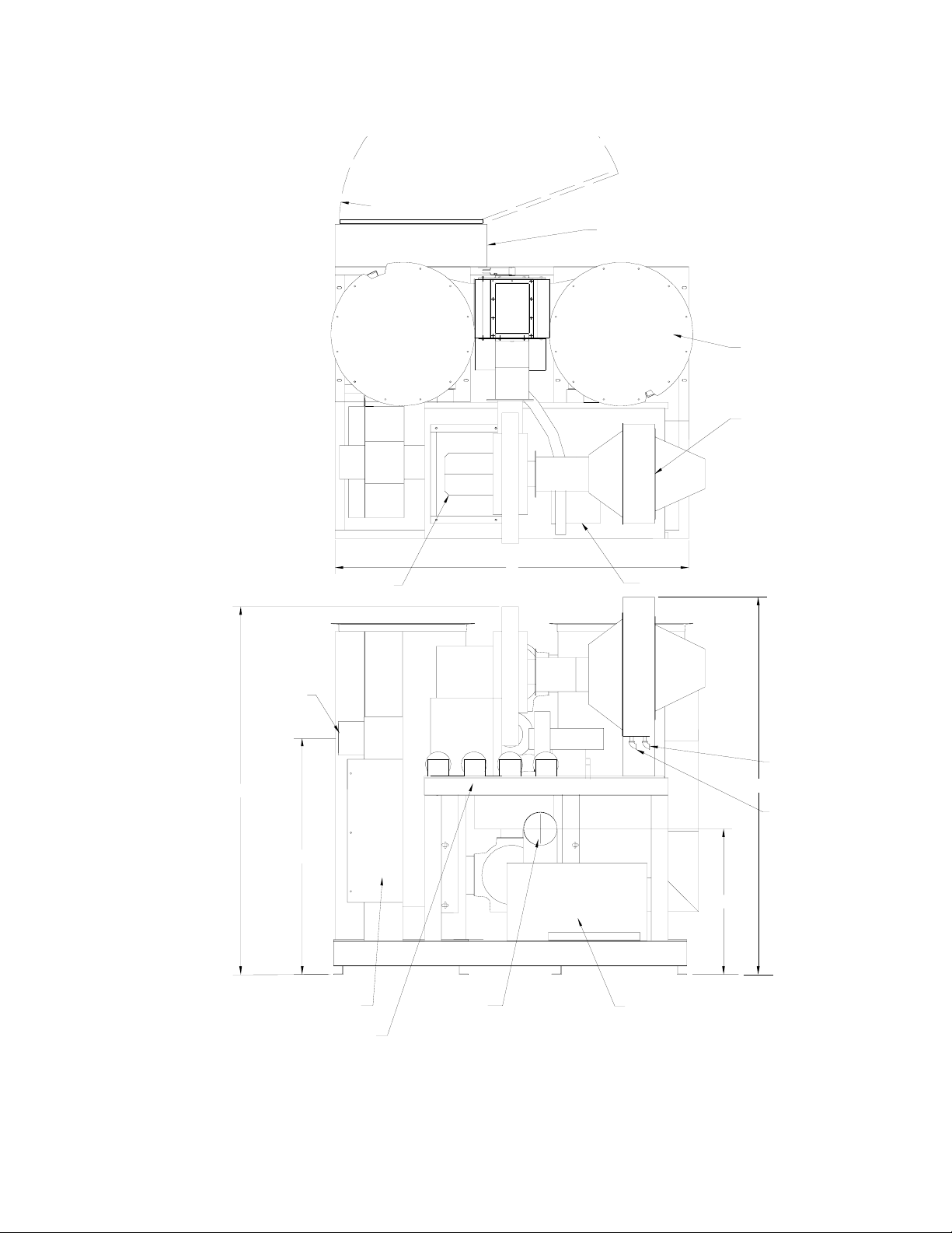
Figure 3: ????????
34" RADIUS
DOOR CLEARANCE
ELECTRICAL ENCLOSURE
AIR OUTLET
B
PROCESS
TOP VIEW
PROCESS BLOWER
DESICCANT TOWER
(LEFT SIDE)
OPTIONAL
AFTERCOOLER
A
REGEN BLOWER AND FILTER
1
2
34
1.5" MPT
INLET
E
1.5" MPT
OUTLET
C
PROCESS HEATER
1) PROCESS BLOWER PRES SWITCH
2) REGEN. DIRTY FILTER PRES. SWITCH
3) REGEN BLOWER PRES. SWITCH
4) DIRTY PROCESS FILTER PRES. SWITCH
?
PROCESS AIR
RETURN, FILTER
INLET
REAR VIEW
PROCESS RETURN
FILTER
D
350-2100 cfm Dryers Chapter 2: Functional Description 15 of 58
SUGGESTED
24"
CLEARANCE
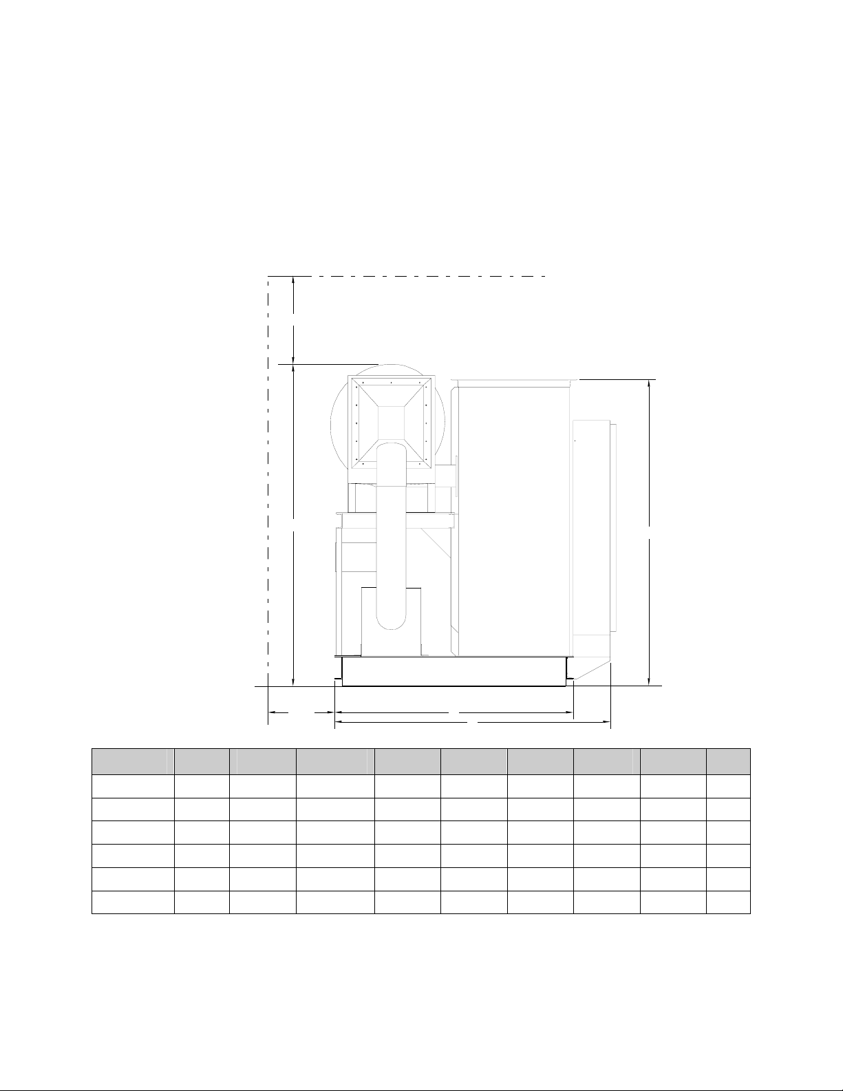
Figure 4: Dryer Dimensions
WD Dryer Dimensions
WD-2100
WD-1800
WD-1500
WD-1250
WD-1000
WD-850
MINIMUM
VERTICAL
100 90½ 82½ 44½ 90.5 88 70½ 91½ 83
100 90½ 82½ 44½ 90.5 88 70½ 91½ 83
100 90½ 82½ 44½ 90.5 88 70½ 91½ 83
84 88 56 34½ 90 87½ 84½ 74 83
All Dimensions are in Inches
Specifications May Change Without Notice
837484½87½9034½568884
837484½87½9034½568884
IHGFEDCBA
LEFT
F
SIDE
I
VIEW
18"
MINIMUM
MAINTENANCE
CLEARANCE
Model A B C D E F G H I
850
1000
1250
1500
1800
2100
84 88 56 34 ½ 90 87 ½ 84 ½ 74 83
84 88 56 34 ½ 90 87 ½ 84 ½ 74 83
84 88 56 34 ½ 90 87 ½ 84 ½ 74 83
100 90 ½ 82 ½ 44 ½ 90 ½ 88 70 ½ 91 ½ 83
100 90 ½ 82 ½ 44 ½ 90 ½ 88 70 ½ 91 ½ 83
100 90 ½ 82 1/2 44 ½ 90 ½ 88 70 ½ 91 ½ 83
G
H
350-2100 cfm Dryers Chapter 2: Functional Description 16 of 58

Chapter 3: Installation
3-1 Work Rules
The installation, operation, and maintenance of this equipment must be conducted in
accordance with all applicable work and safety codes for the installation location. This may
include, but not limited to, OSHA, NEC, CSA, and any other local, national and international
regulations.
1. Read and follow these operating instructions when installing, operating and
maintaining this equipment. If the instructions become damaged or unreadable,
additional copies are available from the manufacturer.
2. Only qualified personnel familiar with this equipment should work on or with this
dryer.
3. Work with approved tools and devices.
4. Disconnect the electricity before maintenance or service. If the dryer is installed with
a power cord that can be unplugged, unplug it. If the dryer is permanently wired to a
power main, a fused power disconnect must be installed to allow the disconnect to be
locked in the "OFF" position. Open and lock out the disconnect installed in the
control enclosure.
3-2 Electrical Connections
The voltage, phase and amp draw information is listed on the serial tag.
; Line voltage must be within ±10% of the voltage listed on the serial tag, or damage
may occur. Phase imbalance must be less than 5%.
; Fulfill all national, state and local safety and electrical code requirements.
; Connection should be made by a qualified electrician.
; Connect main power to the dryer at the disconnect or terminals in the upper right
corner of the control enclosure.
; Install a fused disconnect with a lockout feature in the power main leading to the
dryer.
; The power drop must include a ground wire.
3-3 Check For Proper Blower Rotation
The blowers are rotating properly when air flows from the delivery outlet.
• Incorrect phasing of power leads will cause backward rotation of blower motors and
contamination of the desiccant.
If both blowers are rotating improperly, reverse any two wires at the fused disconnect outside
the dryer or at the disconnect/terminal in the control enclosure. This assures that both blowers
will be rotating in the proper direction.
• Reverse the wires at the motor starters only if one blower is rotating incorrectly.
3-4 Dryer/Drying Hopper Process Air Hose Connection
; Use high-temperature flexible dryer hose or rigid tubing to connect the dryer to the
drying hopper.
350-2100 cfm Dryers Chapter 3: Installation 17 of 58
 Loading...