


OS/OA Series
Gravimetric Batch Blenders
(Standard & CE Models)
Operation, Installation and Service Manual
AEC/HydReclaim, Inc.
801 AEC Drive Wood Dale, IL. 60191 Tel [630] 595-1060 Fax [630] 595-8924 www.aecinternet.com
Part No. A0553549 |
Bulletin No. HR1-605.3 |
|
4/1/02 |

Please note that our address and phone information has changed. Please reference this page for updated contact information.
These manuals are obsolete and are provided only for their technical information, data and capacities. Portions of these manuals detailing procedures or precautions in the operation, inspection, maintenance and repair of the products may be inadequate, inaccurate, and/or incomplete and shouldn’t be relied upon. Please contact the ACS Group for more current information about these manuals and their warnings and precautions.
Parts and Service Department
The ACS Customer Service Group will provide your company with genuine OEM quality parts manufactured to engineering design specifications, which will maximize your equipment’s performance and efficiency. To assist in expediting your phone or fax order, please have the model and serial number of your unit when you contact us. A customer replacement parts list is included in this manual for your convenience. ACS welcomes inquiries on all your parts needs and is dedicated to providing excellent customer service.
For immediate assistance, please contact:
•North, Central and South America, 8am – 5pm CST +1 (800) 483-3919 for drying, conveying, heating and cooling and automation. For size reduction: +1 (800) 229-2919.
North America, emergencies after 5pm CST (847) 439-5855
North America email: acsuscanadacustserv@corpemail.com
•Mexico, Central & South America
Email: acslatinamericacustserv@corpemail.com
•Europe, Middle East & Africa +48 22 390 9720
Email: acseuropecustserv@corpemail.com
•India +91 21 35329112
Email: acsindiacustserv@corpemail.com
•Asia/Australia +86 512 8717 1919
Email: acsasiacustserv@corpemail.com
Sales and Contracting Department
Our products are sold by a worldwide network of independent sales representatives. Contact our Sales Department for the name of the sales representative nearest you.
Let us install your system. The Contract Department offers any or all of these services: project planning; system packages including drawings; equipment, labor, and construction materials; and union or non-union installations.
For assistance with your sales or system contracting needs please Call:
North, Central and South America +1 (262) 641-8600 or +1 (847) 273-7700 Monday–Friday, 8am–5pm CST
Europe/Middle East/Africa +48 22 390 9720
India +91 21 35329112
United States: |
Asia/Australia: |
India |
||
|
|
|
ACS Suzhou |
ACS India |
ACS Schaumburg – Corporate Offices |
Gat No. 191/1, Sandbhor Complex |
|||
1100 E. Woodfield Road |
109 Xingpu Road SIP |
Mhalunge, Chakan, Tal Khed, |
||
Suite 588 |
|
|
Suzhou, China 215126 |
Dist. Pune 410501, India |
Schaumburg, IL 60173 |
Phone: + 86 8717 1919 |
Phone: +91 21 35329112 |
||
Phone: + 1 847 273 7700 |
Fax: +86 512 8717 1916 |
Fax: + 91 20 40147576 |
||
Fax: + 1 847 273 7804 |
Europe/Middle East/Africa: |
|
||
|
|
|
|
|
ACS New Berlin – Manufacturing Facility |
ACS Warsaw |
|
||
2900 S. 160 |
th |
Street |
|
|
|
Ul. Działkowa 115 |
|
||
New Berlin, WI 53151 |
|
|
||
Asia/Australia +86 512 8717 1919 |
|
|
||
Facilities: |
|
|
|
|
ACS offers facilities around the world to service you no matter where you are located. For more information, please visit us at www.acscorporate.com
Phone : +1 262 641 8600 |
02-234 Warszawa |
|
Phone: + 48 22 390 9720 |
||
Fax: + 1 262 641 8653 |
||
Fax: +48 22 390 9724 |
||
|

|
Model # |
Serial # |
Write down your Blender |
________________ |
________________ |
serial numbers here |
_____________ |
_____________ |
for future reference |
________________ |
________________ |
|
________________ |
________________ |
|
________________ |
________________ |
|
________________ |
________________ |
|
________________ |
________________ |
|
________________ |
________________ |
|
________________ |
________________ |
|
________________ |
________________ |
AEC/HydReclaim is committed to a continuing program of product improvement.
Specifications, appearance, and dimensions described in this manual are subject to change without notice.
|
© Copyright AEC/HydReclaim, Inc. 2002 |
All rights reserved. |
Revised April 1, 2002 |
Part No. A0553549 |
Bulletin No. HR1-605A.3 |
ii
Table of Contents
|
|
|
|
...............................................................................Safety Considerations |
5 |
||
|
Annex B Information................................................................................ |
7 |
|
1 |
General Information ............................................................................. |
8 |
|
|
1-1 |
Introduction ...................................................................................... |
8 |
|
1-2 |
Equipment Function ......................................................................... |
8 |
|
1-3 |
Accessories...................................................................................... |
8 |
|
1-4 Customer Service............................................................................. |
8 |
|
|
1-5 Necessary Documents ..................................................................... |
9 |
|
|
1-6 |
System Capabilities.......................................................................... |
9 |
|
1-7 Equipment Covered by this Manual.................................................. |
9 |
|
|
1-8 |
“OS” Series Weigh Blender Mechanical Features .......................... |
10 |
|
1-9 |
“OS” Series Weigh Blender Control Features ................................ |
11 |
|
1-10 |
OS (-E) Series Specifications...................................................... |
12 |
|
1-11 |
OA (-E) Series Specifications....................................................... |
12 |
|
1-12 Model OS/OA Blender System Component Description............... |
13 |
|
|
1-13 |
Pneumatic Slide Gate Below Mixer (Optional).............................. |
22 |
2 |
Safety ................................................................................................... |
|
23 |
|
2-1 Work Rules..................................................................................... |
23 |
|
|
2-2 Tools and Equipment Needed........................................................ |
23 |
|
|
2-3 |
Mechanical Installation ................................................................... |
23 |
|
2-4 |
Safety Considerations .................................................................... |
24 |
|
2-5 |
General Responsibility ................................................................... |
25 |
|
2-6 |
Operator Responsibility .................................................................. |
25 |
|
2-7 |
Maintenance Responsibility............................................................ |
27 |
|
2-8 |
Safety ............................................................................................. |
28 |
|
2-9 |
Electric Safety Interlock Switch (All Models) .................................. |
32 |
|
2-10 |
Air Pressure Safety Circuit ........................................................... |
32 |
3 |
Shipping Information ......................................................................... |
34 |
|
|
3-1 |
Unpacking and Inspection .............................................................. |
34 |
|
3-2 In the Event of Shipping Damages ................................................. |
34 |
|
|
3-3 |
If the Shipment is Not Complete..................................................... |
35 |
|
3-4 |
If the Shipment is Not Correct ........................................................ |
36 |
|
3-5 |
Returns........................................................................................... |
36 |
4 |
Installation ........................................................................................ |
37 |
|
|
4-1 |
Chapter Description and Objectives ............................................... |
37 |
|
4-2 |
Site Requirements.......................................................................... |
37 |
|
4-3 |
Installation Overview ...................................................................... |
41 |
|
4-4 |
Mechanical Installation ................................................................... |
41 |
|
4-5 |
Electrical Installation....................................................................... |
42 |
|
4-6 |
Pneumatic Installation .................................................................... |
43 |
|
4-7 |
Blender Set-up ............................................................................... |
44 |
iii
5 |
Operation ......................................................................................... |
47 |
|
|
5-1 OS/OA Blender Sequence of Operation......................................... |
47 |
|
|
5-2 |
Quick Start Procedure .................................................................... |
47 |
|
5-3 |
Recipe Entry Formats..................................................................... |
48 |
|
5-4 OS & OA Series Control System Menu Structure........................... |
51 |
|
|
5-5 |
Blender Calibration......................................................................... |
52 |
|
5-6 |
Controller Mode Setup ................................................................... |
53 |
|
5-7 Color Change ................................................................................. |
54 |
|
|
5-8 |
Additional Operation Features........................................................ |
56 |
|
5-9 |
Stroke Limiters for Metering Gates................................................. |
82 |
6 Maintenance…………… ……………………………………………….83 |
||
6-1 Work Rules..................................................................................... |
83 |
|
6-2 |
Maintaining Blenders...................................................................... |
83 |
6-3 |
Control Setup ................................................................................. |
84 |
6-4 Optimum OS & OA Series Blender Menu Structure ....................... |
85 |
|
6-5 |
Mechanical ..................................................................................... |
86 |
6-6 |
Electrical......................................................................................... |
87 |
6-7 Pneumatic System Maintenance.................................................... |
91 |
|
7 |
Troubleshooting ................................................................................ |
92 |
|
|
7-1 |
Description and Objectives............................................................. |
92 |
|
7-2 Common Controller Error Codes.................................................... |
95 |
|
8 |
Blender Options ................................................................................ |
96 |
|
9 |
Spare Parts ........................................................................................ |
97 |
|
|
9-1 Recommended Spare Parts List..................................................... |
97 |
|
|
9-2 Model OS/OA Blender System Component Description............... |
103 |
|
10 |
Technical Assistance..................................................................... |
110 |
|
|
10-1 |
Contact Information for Technical Assistance ............................ |
110 |
|
10-2 |
Returned Material Policy ............................................................ |
111 |
|
10-3 Warranty..................................................................................... |
112 |
|
11 |
Safety Tag Information ................................................................... |
113 |
|
|
11-1 OS/OA Blender Safety Tags....................................................... |
113 |
|
|
11-2 Pushbutton and Keypad Tags .................................................... |
114 |
|
|
11-3 Blender Identification (Serial Number) Tag ............................... |
115 |
|
12 Appendix ........................................................................................... |
116 |
||
|
12-1 |
Addendum Service Supervisor Information |
|
|
12-2 |
Electrial Schematics |
|
12-3 Pneumatic Schematic
iv

Safety Considerations
AEC equipment is designed to provide safe and reliable operation when installed and operated within design specifications, following national and local safety codes.
To avoid possible personal injury or equipment damage when installing, operating, or maintaining this equipment, use good judgment and follow these safe practices:
;Follow all SAFETY CODES.
;Wear SAFETY GLASSES and WORK GLOVES.
;Disconnect and/or lock out power before servicing or maintaining the blender.
;Use care when LOADING, UNLOADING, RIGGING, or
MOVING this equipment.
;Operate this equipment within design specifications.
;UNPLUG OR OPEN, TAG, and LOCK ALL DISCONNECT DEVICES before working on equipment. You should remove the fuses and carry them with you.
;GROUND your equipment properly before applying power.
;Use extreme caution when working with your equipment. Keep body parts, tools, clothing, and debris away from vacuum inlets and moving parts.
;Do not jump or bypass any electrical safety components.
;Do not restore power until you remove all tools, test equipment, etc., and the blender and related equipment are fully reassembled.
;Only PROPERLY TRAINED personnel familiar with the information in this manual should work on this equipment.
Page 5 of 118
AEC/HydReclaim
“OS-E” Series Blenders
This blender is manufactured by ACS, Inc. at the ACS-Wood Dale facility:
ACS, Inc.
801 AEC Drive
Wood Dale, IL 60191
Phone: 630.595.1060
Fax: 630.595.6641
The equipment is distributed in Europe by our European facility:
ACS-EUROPE
Daniels Industrial Estate
BATH ROAD
Stroud, Gloucestershire, England
GL5 3TJ
Phone: (44) 1453 768980
Fax: (44) 1453 768990
Page 6 of 118
Annex B Information
The following design information is provided for your reference:
1. |
No modifications are allowed to this equipment that could alter the CE compliance |
|||
2. |
Ambient temperature: |
40 degrees Celsius – Maximum (104 degrees Fahrenheit) |
||
3. |
Humidity range: |
50% relative humidity |
|
|
4. |
Altitude: |
Sea level |
|
|
5. |
Environment: |
Clean, dust-free and non-explosive |
||
6. |
Radiation: |
None |
|
|
7. |
Vibration: |
Minimal, i.e. machine mounting |
||
8. |
Special installation requirements: |
Clean, dry compressed air 1 cfm @ 60 psi |
||
|
|
|
(1.7 m³/hr @ 4.14 bar) |
|
9. |
Allowable voltage fluctuation: |
|
+/- 10% |
|
10. |
Allowable frequency fluctuation: |
Continuous |
+/- 1% |
|
|
|
|
Intermittent |
+/- 2% |
The addition of an auger feeder (RAM option) for regrind will increase the electrical supply requirements of a standard blender.
12. Nominal supply voltage: |
120/1/60 or 220/1/50/60 (Verify on serial number |
|
tag) |
13. Earth ground type: |
TN (system has one point directly earthed through |
|
a protective conductor) |
Power supply should include a neutral power connection.
Over-current protection is supplied in the blender, but additional protection should be supplied by the user.
The plug on the power cord serves as the electrical disconnect device. Unit is not equipped with three-phase motors.
N/A
Blender is not equipped with local lighting. Functional identification
Blender is equipped with a CE mark
Blender is supplied with an operating manual in the language of the destination country. Cable support may be required for power cord, depending on final installation.
No one is required to be in the interior of the electrical enclosure during the normal operation of the unit. Only skilled electricians should be inside the enclosure for maintenance.
Doors can be opened with a screwdriver, but no keys are required. Two-hand control is not required or provided.
All blenders should be moved around and set in a place with a lift truck or equivalent.
There are no frequent repetitive cycles that require manual control repetitive functions are automatic while the blender is operating.
An inspection report detailing the functional test is included with the blender. The machine is not equipped with cableless controls.
Color-coded (harmonized) power cord is sufficient for proper installation.
Page 7 of 118
1 |
General Information |
|
|
1-1 Introduction
We are pleased to supply AEC auxiliary equipment for your facility. We manufacture a complete line of auxiliary equipment to satisfy all of your material handling, process cooling, scrap reclaim, size reduction, and automation requirements. Please feel free to contact your sales representative or our office if you have any questions.
1-2 Equipment Function
All OS/OA blenders are designed to blend plastic pellets and regrind, and supply the blended material to the processing machine. Standard equipment is not designed to blend powder or any other materials.
1-3 Accessories
AEC/HydReclaim offers a variety of standard options for blenders including floor stands, RAM feeders, loading equipment, etc. All accessories are designed and manufactured by AEC, Inc. to ensure proper results for your application.
1-4 Customer Service
The intent of this manual is to familiarize the operator and maintenance personnel with this equipment and help your organization get the maximum service from your equipment. If you have any questions regarding installation, service, repair, custom equipment, or applications, please do not hesitate to contact us for the information required. Prices for additional equipment, accessories, or repair parts will be furnished promptly upon request.
NOTICE: If you desire to use a blender for an application other than that for which it was purchased, please contact your sales representative or our factory to verify compatibility of the equipment with the new process. Misapplication of the equipment could result in injury to the operator or damage to the equipment.
Page 8 of 118
1-5 Necessary Documents
The documents listed below are necessary for proper installation, operation and maintenance of OS/OA Series Gravimetric Batch Blenders. You can obtain additional copies from the AEC/HydReclaim Service Department at AEC, Inc or ACS Europe.
Make sure that appropriate personnel get familiar with these documents:
•This Operation, Installation, and Service manual
•Electrical schematic and connection diagrams
•Pneumatic circuit drawing
•Electric motor and controller information sheets (if equipped)
•Operation and Installation manuals for supplied options and accessories
1-6 System Capabilities
Blending systems are as varied as the applications that they service. This equipment is intended to blend the materials(s) specified at the time of purchase at specific rates.
1-7 Equipment Covered by this Manual
OS Blenders |
OA Blenders |
||
• |
OS-007(E) |
• |
OA-002(E) |
• |
OS-014(E) |
• |
OA-012(E) |
• |
OS-030(E) |
• |
OA-030(E) |
• |
OS-070(E) |
• |
OA-060(E) |
•OS-080(E)
•OS-100(E)
Note: (E) Denotes “CE” models, including 220/1/50
Operation and CE mark
Page 9 of 118

1-8 “OS” Series Weigh Blender Mechanical Features
OS Slide Gate Blender |
OA Auger Blender |
•Efficient Opti-Mixer® and “HC” mixer designs promote homogeneity
•Exclusive diamond design slide gate metering assemblies meter a large range for free flowing pellet materials (OS Series)
•Slide gate stroke limiting restrictors provided for accurate metering of minor ingredients (OS Series)
•Precision auger metering (standard on OA Series, optional on OS)
•Electro-polished 304 SS stainless steel weighing and blending components
•Precision 1/10% span accurate cantilever load cell weighing system
•Removable stainless steel weigh hopper
•Removable stainless steel mixer agitator and mixer wrap
•Mild steel material supply hoppers with clean-out doors and material drains
•Compressed air hose with nozzle for clean-out
•Safety-interlocked system shuts off compressed air and electricity if mixer is opened
Page 10 of 118

1-9 “OS” Series Weigh Blender Control Features
•LCD display operator control panel with two line display and 10’ cable
•Target vs. actual set point verification
•Inventory accumulation for all ingredients
•Audible alarm
•Auxiliary alarm contact
•100 recipe storage book
•Three (3) types of recipe entry procedures available:
9EZ mode (up to 6-component) recipe entry. Color and additives are metered as a percentage of the virgin material.
9Percentage mode recipe entry. Ingredients are metered as a percentage of the overall batch.
9Parts mode recipe entry (i.e. 500:1) Ingredients are metered as a ratio to each other within the batch
•Full control diagnostics
•Parallel printer and RS-485 communications ports
Page 11 of 118
1-10 OS (-E) Series Specifications
OS Series Specifications |
OS-007 |
OS-014 |
OS-030 |
OS-070 |
OS-080 |
OS-100 |
||||
Number of materials blended |
4 |
2 to 6 |
2 to 6 |
2 to 6 |
2 to 6 |
2 to 5 |
||||
Slide gate (adjustable, in (mm)) square |
2 (50) |
2 (50) |
2.5 (63) |
3 (76) |
3 (76) |
4 (101) |
||||
Supply hopper capacity, ft³ (l) |
0.75 (21) |
2 (56) |
3 (85) |
3.9 (110) |
3.9 (110) |
3.9 (110) |
||||
Weigh hopper capacity ft³ (l) |
0.12 |
(3.4) |
0.4 (11) |
0.65 (18) |
1.4 (39) |
1.4 (39) |
1.4 (39) |
|||
Typical batch size, lbs. (kg) |
3 (1.3) |
8 (3.6) |
15 (6.8) |
35 |
(16) |
35 |
(16) |
35 |
(16) |
|
Mixer capacity, lbs. (kg) |
6 (2.7) |
20 (9) |
30 (13.6) |
75 |
(34) |
75 |
(34) |
75 |
(34) |
|
Mixer motor size, HP (kW) |
1/6 (.12) |
1/6 (.12) |
1/2 (.37) |
1/2 |
(.37) |
1/2 |
(.37) |
1/2 |
(.37) |
|
Mixer speed, rpm |
30 |
16 |
22 |
22 |
22 |
22 |
||||
Load cell capacity (2 per blender) |
2 kg ea. |
5 kg ea. |
10 kg ea. |
20 kg ea. |
20 kg ea. |
20 kg ea. |
||||
Blended material discharge opening, in (mm) |
3 (76) |
3 (76) |
4 (101) |
4 (101) |
4 (101) |
4 (101) |
||||
Maximum blending rate (approx.), lbs/hr (kg/hr) |
350 (159) |
700 (318) |
1500(680) |
3500 |
(1590) |
4000 |
(1820) |
5000 |
(2270) |
|
Weight of machine (approx.), lbs (kg) |
145 |
(66) |
200 (91) |
400 (185) |
600 |
(275) |
600 |
(275) |
600 |
(275) |
Shipping weight (approx.), lbs (kg) |
200 |
(91) |
400 (185) |
600 (275) |
850 |
(390) |
850 |
(390) |
850 |
(390) |
1-11 OA (-E) Series Specifications
OA Series Specifications |
OA-002 |
OA-012 |
OA-030 |
OA-060 |
||
Number of materials blended |
2 to 4 |
2 to 6 |
2 to 6 |
2 to 6 |
||
Supply hopper capacity, ft³ (l) |
0.25 (7) |
1.1 (31) |
1.9 - 2.75 |
(54 – 77) |
||
Weigh hopper capacity, ft³ (l) |
0.08 (2.2) |
0.14 (4) |
0.6 (16) |
1.4 (40) |
||
Typical batch size, lbs (kg) |
3 (1.3) |
5 (2.3) |
20 (9) |
50 |
(22) |
|
Mixer type |
Opti-mixer |
|
“HC” |
|
|
|
Mixer capacity, lbs (kg) |
6 (2.7) |
10 (4.5) |
40 |
(18) |
100 (45) |
|
Mixer motor size, HP (kW) |
1/6 (.12) |
1/4 (.18) |
1/2 |
(.37) |
1 (.746) |
|
Mixer speed, rpm |
30 |
50 |
50 |
50 |
||
Load cell capacity (1 per blender except OA-002) |
2 @ 2 kg |
5 kg |
10 kg |
20 kg |
||
Blended material discharge opening |
3 (76) |
3 (76) |
3 (76) |
4 (101) |
||
Maximum blending rate (approx.), lbs./hr. (kg/hr) |
100 (45) |
600 (270) |
1500 (680) |
3000 |
(1360) |
|
Weight of machine (approx.), lbs (kg) |
145 (7.0) |
200 (91) |
450 |
(205) |
600 |
(275) |
Shipping weight (approx.), lbs (kg) |
200 (91) |
400 (185) |
650 |
(295) |
850 |
(390) |
Note: OS/OA features and specifications are subject to change without notice.
Page 12 of 118
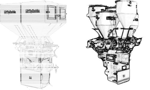
1-12 Model OS/OA Blender System Component Description
This section describes the various components of the blending system. The HydReclaim OS/OA blending system is made up of the following components:
1-12-1 Material Supply Hoppers
1-12-2 Slide Gate Metering Assemblies (OS Series) 1-12-3 Auger Metering Assemblies (OA Series) 1-12-4 Weigh Hopper
1-12-5 Weigh Hopper Dump Valve
1-12-6 Mix Chamber
1-12-7 Operator Control Panel
OS |
OA |
|
(with optional Opti-Mixer™) |
Page 13 of 118

1-12-1 Material Supply Hoppers
The material supply hoppers are located on top of the blender frame. These hoppers store a supply of material for the individual metering devices. They are sized based on the total throughput of the blender.
The OS/OA blending system does not include any level indication devices on the unit. Optional low-level sensors and low-level alarm panels are available. The blender controller will alarm if it runs out of material while trying to make a batch, but low-level sensors will alert floor personnel to the problem sooner.
Each hopper is equipped with a sight glass and/or access door.
HINGED POLYCARBONATE
ACCESS DOOR


 DOOR LATCH
PNEUMATIC SAFETY SWITCH (IF EQUIPPEDOLDER MODELS ONLY)

 SIGHT GLASS (IF EQUIPPED)
DRAIN PORT WITH PLUG
Typical Material Supply Hoppers
Page 14 of 118

1-12-2 Slide Gate Metering Assemblies (OS Series)
Air operated slide gates are provided to meter the majority of pellet ingredients on the OS blenders.
Important! The metering range assumes 1/8” diameter free-flowing plastic pellets weighing approximately 35 lbs./cu. ft. This is meant to be an approximate sizing recommendation and can vary with different bulk density resins, pellet configuration, etc.
A stroke limiter (included) can be installed on the metering gates to limit their travel. This device decreases the stroke of the gate and reduces the metering orifice of the valve. The unique diamond gate provides a square opening at any stroke length, providing more consistent flow from smaller valve openings than conventional slide gates. This stroke limiter may be necessary to accurately meter low percentage ingredients.
The air cylinders operating the slide gate are rugged, stainless steel cylinders designed for industrial use.
DIAMOND GATE OPEN
The unique HydReclaim diamond gate provides a constant aspect opening, that remains square regardless of the stroke length of the cylinder. This design provides a wider cross sectional opening when approaching a closed position, and provides better flow of plastic pellets out of the opening.
DIAMOND GATE 1/2 CLOSED
DIAMOND GATE 3/4 CLOSED
DIAMOND GATE CLOSED
WARNING!
Slide gates create a pinch-point hazard.
Always disconnect and lockout all electrical power and pneumatic (i.e. compressed air) sources prior to servicing or cleaning any HydReclaim blender, including all OS/OA Series models. Failure to do so may result in serious injury.
Page 15 of 118

Each of the diamond gate air cylinders is actuated by a solenoid valve, which are controlled by the blender.
When the solenoid valve is energized, it opens the metering valve cylinder. When the solenoid valve is de-energized, it closes the metering valve cylinder.
If the power is interrupted to the blender, the metering valves will return to the closed position, to prevent material from over-filling the weigh hopper/mix chamber.
Important! If the blender is in metering mode with one of the slide gates open, do not open the front door of the blender!
The safety switch shuts off the air supply to the blender. An open feeder slide gate stays open, and an overflow of the weigh hopper can occur!
Page 16 of 118
1-12-3 Auger Metering Assemblies (OA Series)
OA Series blenders are equipped with auger metering units, including the following components:
•Cast aluminum feeder bodies
•Cast aluminum motor mounts
•Heavy-duty AC gear motors (Optional DC drives are available)
•Drain spouts with slide gate shut-off
•Machined steel auger
•Cast aluminum auger housing
•Spun aluminum material supply hoppers
•Cover with cut-out for Whitlock SRC vacuum receivers
Optimum OA Series available with a Choice of Mixers
OA with standard “HC” mixer |
|
|
OA with optional Opti-Mixer® |
||||||||||||||||||||||||||||||||||||||
|
|
|
|
|
|
|
|
|
|
|
|
|
|
|
|
|
|
|
|
|
|
|
|
|
|
|
|
|
|
|
|
|
|
|
|
|
|
|
|
|
|
|
|
|
|
|
|
|
|
|
|
|
|
|
|
|
|
|
|
|
|
|
|
|
|
|
|
|
|
|
|
|
|
|
|
|
|
|
|
|
|
|
|
|
|
|
|
|
|
|
|
|
|
|
|
|
|
|
|
|
|
|
|
|
|
|
|
|
|
|
|
|
|
|
|
|
|
|
|
|
|
|
|
|
|
|
|
|
|
|
|
|
|
|
|
|
|
|
|
|
|
|
|
|
|
|
|
|
|
|
|
|
|
|
|
|
|
|
|
|
|
|
|
|
|
|
|
|
|
|
|
|
|
|
|
|
|
|
|
|
|
|
|
|
|
|
|
|
|
|
|
|
|
|
|
|
|
|
|
|
|
|
|
|
|
|
|
|
|
|
|
|
|
|
|
|
|
|
|
|
|
|
|
|
|
|
|
|
|
|
|
|
|
|
|
|
|
|
|
|
|
|
|
|
|
|
|
|
|
|
|
|
|
|
|
|
|
|
|
|
|
|
|
|
|
|
|
|
|
|
|
|
|
|
|
|
|
|
|
|
|
|
|
|
|
|
|
|
|
|
|
|
|
|
|
|
|
|
|
|
|
|
|
|
|
|
|
|
|
|
|
|
|
|
|
|
|
|
|
|
|
|
|
|
|
|
|
|
|
|
|
|
|
|
|
|
|
|
|
|
|
|
|
|
|
|
|
|
|
|
|
|
|
|
|
|
|
|
|
|
|
|
|
|
|
|
|
|
|
|
|
|
|
|
|
|
|
|
|
|
|
|
|
|
|
|
|
|
|
|
|
|
|
|
|
|
|
|
|
|
|
|
|
|
|
|
|
|
|
|
|
|
|
|
|
|
|
|
|
|
|
|
|
|
|
|
|
|
|
|
|
|
|
|
|
|
|
|
|
|
|
|
|
|
|
|
|
|
|
|
|
|
|
|
|
|
|
|
|
|
|
Multiple regrinds and |
Pellets and one |
more difficult materials |
free-flowing regrind |
Page 17 of 118

1-12-4 Weigh Hopper
The weigh hopper on the OS/OA blender is used to weigh each batch of material, and includes an air-operated discharge valve. After the batch is weighed and the level sensor in the lower mix section is uncovered, the valve will open and discharge the batch into the mixer with the existing blended material. The discharge valve is also provided with a quick disconnect so the weigh hopper can be removed for cleaning.
On an OS blender, the weigh hopper rests on each side on a precision cantilever load cell. To remove the weigh hopper, lift the hopper from the bottom, hold the discharge valve closed, and slide it out once clear of the locating tab on the bracket above the load cell.
Once the hopper has been cleaned, reposition it onto the load cell brackets, using care not to damage the load cells. Position the hopper as close to the center position between the load cells as possible.
Important! Use care when replacing the weigh hopper, since the load cells are delicate weighing instruments and can be easily damaged. Do not  use force to push in the weigh hopper. If it is positioned properly,
it will slide in very easily.
Load cells, if damaged, will have to be sent back to the manufacturer for testing and evaluation.
LOCATING TABS
LOAD CELL |
WEIGH HOPPER |
LOAD CELL |
AIR CYLINDER
DISCHARGE VALVE
The OA-HC style weigh hopper is bolted in place, and is generally not removed.
Page 18 of 118

1-12-5 Weigh Hopper Discharge Valve
The weigh hopper discharge valve holds the material until it is dumped into the mixing section. The cylinder is actuated by a solenoid in the valve stack on the rear of the blender.
In looking at the pneumatic circuit, you can see that the air regulator controls the flow of air to the valve stack. When the weigh hopper discharge cylinder solenoid valve is not electrically energized, it will provide air pressure to the air cylinder and hold the shaft in an extended position, holding the dump valve closed.
When the air cylinder is actuated, the air pressure to the dump valve will be removed, causing it to open.
The air cylinder on the weigh hopper includes a spring return to allow the cylinder to retract in the absence of air pressure on the cylinder.
This will cause the dump valve to open.
CAUTION! The pneumatic system used on the OS/OA, like all pneumatic systems, is highly sensitive to dirty, wet or contaminated air. If dirt, water, or any other air-borne contaminates enter the system, the components could be damaged and injury to the operator could result. A proper air supply must be supplied to the blender.
When the safety circuit is disabled, the air pressure to the cylinder will drop off by shutting off all the air supply to the valve stack with the pilot operated master air valve. This will also cause the weigh hopper discharge door to open.
Page 19 of 118
1-12-6 Mix Chamber
All of the HydReclaim batch blenders are equipped with an integral mix chamber. The mix chamber holds multiple batches of material so any variations in a batch are averaged over time.
1-12-6-1 Opti-Mixer™
The Opti-mixer™ is designed to provide bi-directional mixing action and can be easily taken apart for cleaning. This design is standard on all OS blenders, and is optional on all OA models.
1-12-6-2 “HC” Mixer
The “HC” Mixer features an open wheel design and is best used for multiple regrind materials. It is standard on all OA models.
WARNING!
Never reach into the mix section of the blender without disconnecting the power or air supply.
Serious injury can result from getting your hand caught in the rotating mixer!
Page 20 of 118
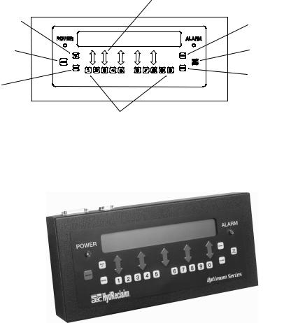
1-12-7 Operator Control Panel
The operator control panel includes an 8 foot (2.4 m) cable and can be remote mounted adjacent to the blender. The panel can be unplugged and removed if necessary.
The controller includes an embedded computer. This design provides excellent blender performance along with an easily replaceable control panel in the unlikely failure of any computer or electronic part.
The display and keypad menu format is very simple. After installation and setup, simply enter in the recipe and start the blender.
If it is desired to have a local display and control of the blender closer to a remote operator station, an optional RS485 remote control panel
(RCP) is available.
|
Adjust component settings in EZ recipe mode |
“Backup” key |
“Start” blend cycle key |
“Abort” cycle key |
Stop at “End of cycle” key |
“Enter” key |
“Clear” key |
|
|
|
Numeric entry keys |
Note: The panel keypad on your unit may be slightly different than shown.
Page 21 of 118

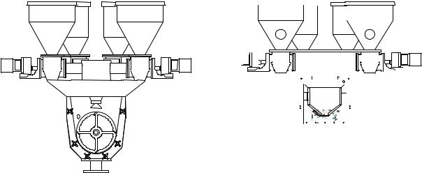
1-13 Pneumatic Slide Gate Below Mixer (Optional)
The OS/OA blending system can be equipped with an optional pneumatic slide gate below the mixing chamber. The gate is used in applications when the blender is mounted above a large hopper, or for gaylord filling, etc. This gate holds the material in the mixing section, to ensure that it is properly mixed.
Control of the mixer function is described below, and is determined by the position of the “knife gate switch” located on the side of the back control panel.
Mixer Slide Gate Switch Positions
AUTO
OPEN CLOSE
Slide gate closes when mixer starts and opens when mixer stops
Slide gate open all the time Slide gate closed all the time
TYPICAL CENTRAL BLENDER LAYOUT
Blender
Pneumatic Slide Gate Below Mixer
Surge Bin
 Take-off Compartment
 Floor Stand
Page 22 of 118

Safety |
2 |
|
|
2-1 Work Rules
Install, operate, and maintain this equipment according to applicable work and safety codes for your location. This includes OSHA, CE, NEC, CSA, SPI, and many other local, national, and international regulations. Obey these specific work rules:
Read and follow the instructions in this manual before installing, operating, or maintaining any equipment. Additional copies are available from AEC, Inc.
Only qualified persons should work on, or with, this equipment.
Work only with approved tools and devices.
Disconnect and lock out power while working on this equipment.
2-2 Tools and Equipment Needed
You’ll need the following:
•Hand tools
•Fork lift or overhead lift
•Wire, conduit, and fittings for wiring runs (if receptacle is not already in place)
•Mounting bolts with nuts and washers
•Compressed air tubing and fittings
2-3 Mechanical Installation
Blenders may be mounted on the machine, a stand, or a mezzanine. Be sure it is securely attached and additional bracing is used if necessary. The sections on the following pages explain general installation rules.
Read manual thoroughly before installing blender.
Use approved safety straps or chains to lift the blender at the marked lifting points.
Page 23 of 118

2-4 Safety Considerations
The terms NOTICE, CAUTION, WARNING, and DANGER have specific meanings in this manual. See Section 11 for a complete list of specific safety warning information.
A NOTICE is used to indicate a statement of company policy directly or indirectly related to the safety of personnel or protection of property.
A CAUTION indicates a potentially hazardous situation which, if not avoided, may result in minor or moderate injury.
A WARNING indicates a potentially hazardous situation which, if not avoided could result in death or serious injury.
A DANGER indicates an imminently hazardous situation which, if not avoided, will result in death or serious injury. This word will be limited to the most serious situation(s).
The term IMPORTANT emphasizes areas where equipment damage could result, or provides additional information to make a step or procedure easier to understand. Disregarding information marked
IMPORTANT would not be likely to cause personal injury.
REPORTING A SAFETY DEFECT
NOTE: If you believe that your equipment has a defect which could cause injury, you should immediately discontinue its use and inform AEC, Inc., at our address listed in this manual.
The principle factors which can result in injury are:
1. Failure to follow proper operating and clean-out procedures, i.e. lockout/tagout.
2. Failure to maintain a clean and safe working environment.
Page 24 of 118
2-5 General Responsibility
NO MATTER WHO YOU ARE…
Safety is important. Owners, operators, and maintenance personnel must realize that every day, safety is a vital aspect of their jobs.
If your main concern is loss of productivity, remember this: Production is always affected in a negative way following an accident. The following are some of the reasons, which can affect your production:
•Loss of a skilled operator (temporarily or permanently)
•Breakdown of shop morale
•Costly damage to equipment
•Down-time
An effective safety program is responsible and economically sound.
Organize a safety committee or group, and hold regular meetings. Promote this group from the management level. Through this group, the safety program can be continually reviewed, maintained, and improved. Keep minutes or a record of the meetings.
Hold daily equipment inspections in addition to regular maintenance checks. You will keep your equipment safe for production and exhibit your commitment to safety.
Please read and use this manual as a guide to equipment safety. This manual contains safety warnings throughout, specific to each function and point of operation.
2-6 Operator Responsibility
The operator’s responsibility does not end with efficient production. The operator usually has the most daily contact with the blender and intimately knows its capabilities and limitations.
Plant and personnel safety is sometimes forgotten in the desire to meet incentive rates, or through a casual attitude toward machinery formed over a period of months or years. Your employer probably has established a set of safety rules in your workplace. Those rules, this manual, or any other safety information will not keep you from being injured while operating your equipment.
ONLY YOU can make safety work for you by constantly thinking about what is safe and what is not. It is often the “just once” that an operator reaches into a blender to remove material and it results in serious injury.
Learn and always use safe operation. Cooperate with co-workers to promote safe practices. Immediately report any potentially dangerous situation to your supervisor or appropriate person.
Page 25 of 118
REMEMBER:
•NEVER place your hands or any part of your body in any dangerous location.
•NEVER operate, service, or adjust the blender without appropriate training and first reading and understanding this manual.
•NEVER try to pull material out of the blender with your hands while it is running!
•Before you start the blender check the following:
•Remove all tools from the blender;
•Be sure no objects (tools, nuts, bolts, clamps, bars) are laying in the metering or mixing area;
•If your blender has been inoperative or unattended, check all settings before starting the unit.
•At the beginning of your shift and after breaks, verify that the controls and other auxiliary equipment are functioning properly.
•Keep all safety guards in place and in good repair. NEVER attempt to bypass, modify, or remove safety guards. Such alteration is not only unsafe, but will void the warranty on your equipment.
•When changing control settings to perform a different mode of operation, be sure selector switches are correctly positioned. Locking selector switches should only be adjusted by authorized personnel and the keys removed after setting.
•Report the following occurrences IMMEDIATELY:
•unsafe operation or condition
•unusual blender action
•leakage
•improper maintenance
•NEVER stand or sit where you could slip or stumble into the blender while working on it.
•DO NOT wear loose clothing or jewelry, which can be caught while working on a blender. Also cover or tie back long hair.
•Clean the blender and surrounding area DAILY, and inspect the machine for loose, missing or broken parts.
•Shut off power to the blender when it is not in use. Turn the switch to the OFF position, or unplug it from the power source.
Page 26 of 118
2-7 Maintenance Responsibility
Safety is essential to the good health of both operator and machine. If you are a maintenance worker, you must make safety a priority in order to effectively repair and maintain equipment.
BEFORE REMOVING, ADJUSTING, OR REPLACING PARTS ON A MACHINE, REMEMBER TO DO THE FOLLOWING:
•BLEED all air pressure from system components (refer to the Maintenance Section of this manual.)
•TURN OFF all air and electric supplies and all accessory equipment at the machine.
•DISCONNECT AND LOCK OUT electrical and pneumatic power, and attach warning tags to the disconnect switch and air shutoff valve.
When you need to perform maintenance or repair work on a blender above floor level, use a solid platform or a hydraulic elevator. If there is a permanently installed catwalk on your blender, use it. The work platform should have secure footing and a place for tools and parts. DO NOT climb on blenders, machines, or work from ladders.
If you need to repair a large component, use appropriate handling equipment.
Before you use handling equipment (portable “A” frames, electric boom trucks, fork trucks, overhead cranes) be sure the load does not exceed the capacity of the handling equipment or cause it to become unstable.
Carefully test the condition of lifting cables, chains, ropes, slings, and hooks before using them to lift a load.
Be sure that all non-current carrying parts of electrical apparatus, electrical component enclosures, and the blender frame are correctly connected to earth ground with an electrical conductor that complies with current codes. Install in accordance with national and local codes, which apply.
When you have completed the repair or maintenance procedure, check your work, remove your tools, rigging, and handling equipment.
Do not restore power to the blender until all persons are clear of the area. Start and run the blender until you are sure all parts are functioning correctly.
BEFORE you turn the blender over to the operator for production, verify all guards and safety devices are in place and functioning properly.
Page 27 of 118
2-8 Safety
2-8-1 Description and Objectives
This section includes information on safety devices and procedures that are inherent to the OS/OA blending system. This manual is not intended to supersede or alter safety standards established by the user of this equipment. Instead, the material contained in this section is recommended to supplement these procedures in order to provide a safer working environment.
At the completion of this section, the operator and maintenance personnel will be able to:
•Identify and locate specific safety devices.
•Understand the proper use of the safety devices provided.
•Describe the function of the safety devices.
2-8-2 Safety Circuit Standards
Safety circuits used in industrial systems protect the operator and maintenance personnel from dangerous energy. They also provide a means of locking out or isolating the energy for servicing equipment.
Various agencies have contributed to the establishment of safety standards that apply to the design and the manufacture of automated equipment. The Occupational Safety and Health Administration (OSHA) and the Joint Industrial Council (JIC) are just a few of the organizations that have joined with the plastics industry to develop safety standards.
Every effort has been made to incorporate these standards into the design of the OS/OA blending system; however, it is the responsibility of the personnel operating and maintaining the equipment to familiarize themselves with the safety procedures and the proper use of any safety devices.
Page 28 of 118

2-8-3 Fail Safe Operation
If a safety device or circuit should fail, the design must be such that the failure causes a “Safe” condition. As an example, a safety switch must be a normally open switch. The switch must be held closed with the device it is to protect. If the switch fails, it will go to the open condition, tripping out the safety circuit.
At no time should the safety device fail and allow the operation to continue. For example, if a safety switch is guarding a motor, and the safety switch fails, the motor should not be able to run.
2-8-4 Safety Device Lock-Outs
Some safety devices disconnect electrical energy from a circuit. The safety devices that are utilized on HydReclaim OS/OA models are primarily concerned with the pneumatics and electrical power disconnection, and the disabling of moving parts that may need to be accessed during the normal operation of the machine.
Some of the safety devices utilize a manual activator. This is the method of initiating the safety lock out. This may be in the form of a plug, disconnect plug, lever or a handle. Within this lockable handle, there may be a location for a padlock. Personnel servicing the equipment should place a padlock in the lockout handle.
WARNING!Always disconnect and lockout all electrical power and pneumatic (i.e. compressed air) sources prior to servicing or cleaning any HydReclaim blender, including all OS/OA units. Failure to do so may result in serious injury.
At no time must anyone remove the lockout or reconnect the twist plug, other than the person who installed the lockout or who unplugged the twist plug.
Page 29 of 118
 Loading...