


 Loading...
Conveying System
Mechanical Components
Part Number: A0536580
Bulletin Number: WH2-605A.6
Effective: 3/1/05
Write Down Your Serial Numbers Here For Future Reference:
_________________________ _________________________
_________________________ _________________________
_________________________ _________________________
We are committed to a continuing program of product improvement.
Specifications, appearance, and dimensions described in this manual are subject to change without notice.
DCN No. ____________
© Copyright 2005 All rights reserved.

Please note that our address and phone information has changed. Please reference this page for updated contact information.
These manuals are obsolete and are provided only for their technical information, data and capacities. Portions of these manuals detailing procedures or precautions in the operation, inspection, maintenance and repair of the products may be inadequate, inaccurate, and/or incomplete and shouldn’t be relied upon. Please contact the ACS Group for more current information about these manuals and their warnings and precautions.
Parts and Service Department
The ACS Customer Service Group will provide your company with genuine OEM quality parts manufactured to engineering design specifications, which will maximize your equipment’s performance and efficiency. To assist in expediting your phone or fax order, please have the model and serial number of your unit when you contact us. A customer replacement parts list is included in this manual for your convenience. ACS welcomes inquiries on all your parts needs and is dedicated to providing excellent customer service.
For immediate assistance, please contact:
•North, Central and South America, 8am – 5pm CST +1 (800) 483-3919 for drying, conveying, heating and cooling and automation. For size reduction: +1 (800) 229-2919.
North America, emergencies after 5pm CST (847) 439-5855
North America email: acsuscanadacustserv@corpemail.com
•Mexico, Central & South America
Email: acslatinamericacustserv@corpemail.com
•Europe, Middle East & Africa +48 22 390 9720
Email: acseuropecustserv@corpemail.com
•India +91 21 35329112
Email: acsindiacustserv@corpemail.com
•Asia/Australia +86 512 8717 1919
Email: acsasiacustserv@corpemail.com
Sales and Contracting Department
Our products are sold by a worldwide network of independent sales representatives. Contact our Sales Department for the name of the sales representative nearest you.
Let us install your system. The Contract Department offers any or all of these services: project planning; system packages including drawings; equipment, labor, and construction materials; and union or non-union installations.
For assistance with your sales or system contracting needs please Call:
North, Central and South America +1 (262) 641-8600 or +1 (847) 273-7700 Monday–Friday, 8am–5pm CST
Europe/Middle East/Africa +48 22 390 9720
India +91 21 35329112
United States: |
Asia/Australia: |
India |
||
|
|
|
ACS Suzhou |
ACS India |
ACS Schaumburg – Corporate Offices |
Gat No. 191/1, Sandbhor Complex |
|||
1100 E. Woodfield Road |
109 Xingpu Road SIP |
Mhalunge, Chakan, Tal Khed, |
||
Suite 588 |
|
|
Suzhou, China 215126 |
Dist. Pune 410501, India |
Schaumburg, IL 60173 |
Phone: + 86 8717 1919 |
Phone: +91 21 35329112 |
||
Phone: + 1 847 273 7700 |
Fax: +86 512 8717 1916 |
Fax: + 91 20 40147576 |
||
Fax: + 1 847 273 7804 |
Europe/Middle East/Africa: |
|
||
|
|
|
|
|
ACS New Berlin – Manufacturing Facility |
ACS Warsaw |
|
||
2900 S. 160 |
th |
Street |
|
|
|
Ul. Działkowa 115 |
|
||
New Berlin, WI 53151 |
|
|
||
Asia/Australia +86 512 8717 1919 |
|
|
||
Facilities: |
|
|
|
|
ACS offers facilities around the world to service you no matter where you are located. For more information, please visit us at www.acscorporate.com
Phone : +1 262 641 8600 |
02-234 Warszawa |
|
Phone: + 48 22 390 9720 |
||
Fax: + 1 262 641 8653 |
||
Fax: +48 22 390 9724 |
||
|

Shipping Info
Unpacking and Inspection
You should inspect the mechanical components of your conveying system for possible shipping damage.
Thoroughly check the equipment for any damage that might have occurred in transit, such as broken or loose wiring and components, loose hardware and mounting screws, etc.
In the Event of Shipping Damage
According to the contract terms and conditions of the Carrier, the responsibility of the Shipper ends at the time and place of shipment.
Notify the transportation company’s local agent if you discover damage.
Hold the damaged goods and packing material for the examining agent’s inspection. Do not return any goods before the transportation company’s inspection and authorization.
File a claim with the transportation company. Substantiate the claim by referring to the agent’s report. A certified copy of our invoice is available upon request. The original Bill of Lading is attached to our original invoice. If the shipment was prepaid, write us for a receipted transportation bill.
Advise customer service regarding your wish for assistance and to obtain an RMA (return material authorization) number.
If the Shipment is Not Complete
Check the packing list as back-ordered items are noted on the packing list. You should have: Mechanical Components of Conveying System
Bill of lading Packing list
Operating and Installation packet
Electrical schematic and panel layout drawings Component instruction manuals
Re-inspect the container and packing material to see if you missed any smaller items during unpacking.
If the Shipment is Not Correct
If the shipment is not what you ordered, contact the shipping department immediately. For shipments in the United States and Canada, call 1 (800) 229-2919; for all other countries, call our international desk at (508) 399-6400. Have the order number and item number available.
Hold the items until you receive shipping instructions.
Returned Material Policy
Do not return any damaged or incorrect items until you receive shipping instructions from the shipping department.
Conveying System Mechanical Components |
ii |
Credit Returns
Prior to the return of any material authorization must be given by the manufacturer. A RMA number will be assigned for the equipment to be returned.
Reason for requesting the return must be given.
ALL returned material purchased from the manufacturer returned is subject to 15% ($75.00 minimum) restocking charge.
ALL returns are to be shipped prepaid.
The invoice number and date or purchase order number and date must be supplied.
No credit will be issued for material that is not within the manufacturer’s warranty period and/or in new and unused condition, suitable for resale.
Warranty Returns
Prior to the return of any material, authorization must be given by the manufacturer. A RMA number will be assigned for the equipment to be returned.
Reason for requesting the return must be given. All returns are to be shipped prepaid.
The invoice number and date or purchase order number and date must be supplied.
After inspecting the material, a replacement or credit will be given, at the manufacturer’s discretion. If the item is found to be defective in materials or workmanship, and it was manufactured by our company, purchased components are covered under their specific warranty terms.
Conveying System Mechanical Components |
iii |
Table of Contents
|
|
|
................................................................CHAPTER 1: SAFETY |
9 |
|
1-1 How to Use This Manual ............................................................................................. |
9 |
|
|
Safety Symbols Used in this Manual..................................................................... |
9 |
1-2 |
Warnings and Precautions ........................................................................................ |
10 |
1-3 |
Responsibility ............................................................................................................ |
11 |
|
General Responsibility......................................................................................... |
11 |
|
Operator Responsibility ....................................................................................... |
12 |
|
Maintenance Responsibility................................................................................. |
13 |
|
Reporting a Safety Defect ................................................................................... |
13 |
CHAPTER 2: FUNCTIONAL DESCRIPTION........................... |
14 |
|
2-1 Models Covered in This Manual................................................................................ |
14 |
|
2-2 |
General Description................................................................................................... |
14 |
|
Basic System Components ................................................................................. |
14 |
|
Basic System Types............................................................................................ |
15 |
|
Conveying Distance ............................................................................................ |
15 |
|
Equipment Cycle ................................................................................................. |
15 |
2-3 Standard Features & Options.................................................................................... |
16 |
|
|
SRI Series Inventory Vacuum Receivers ............................................................ |
16 |
|
Pumps ................................................................................................................. |
18 |
|
Blowback Pumps................................................................................................. |
20 |
|
VTTV TurboVac Series Pumps ........................................................................... |
22 |
|
APC Centrifugal Pumps ...................................................................................... |
26 |
|
SRH/SRC Vacuum Receivers ............................................................................. |
28 |
|
Vacuum Receivers .............................................................................................. |
32 |
|
Atmospheric Valves............................................................................................. |
36 |
|
Sequence T-Valves ............................................................................................. |
37 |
|
Cartridge-Style Vortex Filter Chamber ................................................................ |
38 |
|
FC Series Bag-Style Filters ................................................................................. |
40 |
|
ACA Series Filter Chambers ............................................................................... |
40 |
|
AFC-S Series Filters............................................................................................ |
42 |
|
Take-Off Compartments and Pickup Tubes ........................................................ |
43 |
2-4 Safety Devices and Interlocks ................................................................................... |
46 |
|
CHAPTER 3: INSTALLATION.................................................. |
48 |
|
3-1 |
Uncrating the Equipment........................................................................................... |
48 |
3-2 Rigging and Placing Mechanical Components.......................................................... |
48 |
|
|
Installing the Pump Package............................................................................... |
48 |
|
Installing the Control Panel ................................................................................. |
51 |
|
Installing Material/Vacuum Tubing ...................................................................... |
51 |
|
Installing VFC or FC Filter Chambers.................................................................. |
56 |
|
Installing ACA Series Filter Chambers ................................................................ |
57 |
|
Installing Vacuum Receivers and Inventory/Vacuum Receivers ......................... |
58 |
|
Installing the Safety Filter .................................................................................... |
58 |
3-3 Compressed Air Blowback Connection ..................................................................... |
60 |
|
3-4 |
Implosion Blowback Connection ............................................................................... |
60 |
Conveying System Mechanical Components |
iv |
|
Adjusting the Vacuum Receiver Counterbalance................................................ |
62 |
|
Installing the Pickup Probe.................................................................................. |
62 |
|
Installing the Grinder Take-off Attachment.......................................................... |
63 |
|
Installing and Adjusting the Take-off Compartment............................................. |
63 |
|
Adjusting Fast Take-off (FCO) Compartments .................................................... |
64 |
|
Installing the Powder Check Adapter (Box Style; EVTO; FEVTO only) .............. |
64 |
3-5 |
Compressed Air Connections.................................................................................... |
66 |
|
Making ACA Series Filter Chamber Compressed Air Connections..................... |
66 |
|
Making Pump Compressed Air Connections....................................................... |
66 |
|
Connecting Vacuum Receivers with Atmospheric Valve Compressed Air Lines 66 |
|
|
Connecting Vacuum Receivers with Sequence-T Valve Compressed Air Lines.67 |
|
|
Running Remote Proportioning Valve or Proportioning Vacuum Receiver |
|
|
Compressed Air Lines ......................................................................................... |
68 |
3-6 |
Electrical Connections............................................................................................... |
69 |
|
Making ACA Series Filter Chamber Electrical Connections................................ |
69 |
|
Making Pump Power Drop Wiring Connections .................................................. |
69 |
|
Making Control Panel Power Drop Wiring Connections ...................................... |
69 |
|
Connecting the Control Panel to Vacuum Receivers .......................................... |
70 |
|
Installing Station Bypass Switches...................................................................... |
72 |
|
Connecting the Control Panel to the Pump Package .......................................... |
73 |
3-7 |
Initial Start-up ............................................................................................................ |
80 |
|
Making Startup Checks ....................................................................................... |
80 |
|
Adjusting Sight Glass Proximity Sensor Sensitivity ............................................. |
80 |
|
Adjusting Air Pulse Duration: All Models ............................................................. |
81 |
|
ACA Series Filter Chamber Pre-Operation Checklist.......................................... |
81 |
|
Adjusting Time Between Air Pulses on ACA Filters ............................................ |
81 |
|
Adjusting the Number of Air Pulses..................................................................... |
81 |
|
Starting ACA Series Filter Chamber Units........................................................... |
82 |
|
Adjusting Proximity Sensor Sensitivity ................................................................ |
82 |
CHAPTER 4: OPERATION....................................................... |
83 |
|
4-1 Start-up...................................................................................................................... |
83 |
|
|
Starting ACA Series Filter Chamber Units........................................................... |
83 |
4-2 |
Operation Procedures ............................................................................................... |
83 |
|
Vacuum Switch (VS) Operation........................................................................... |
83 |
|
High Vacuum Relief Regulator Operation ........................................................... |
84 |
4-3 Shut-down ................................................................................................................. |
84 |
|
CHAPTER 5: MAINTENANCE ................................................. |
85 |
|
5-1 |
Preventative Maintenance Schedule......................................................................... |
85 |
5-2 |
Preventative Maintenance......................................................................................... |
86 |
|
Maintaining Pump Packages............................................................................... |
86 |
|
Maintaining Filter Chambers................................................................................ |
88 |
|
Inspecting ACA Series Filter Chamber Filter Bags.............................................. |
88 |
|
Maintaining VTPB Series Vacuum Power Unit Non-Reversing Valves ............... |
89 |
|
Servicing and Reassembling Lower Valves ........................................................ |
94 |
|
Maintaining Vacuum Receivers and Filter/ Receiver Combinations.................... |
94 |
5-3 |
Cleaning the Collection Bin (All Models Except VFC 225 and VFC 1000)............... |
95 |
5-4 Cleaning the Filter Shroud (VFC 225 and VFC 1000 Only) ...................................... |
95 |
|
5-5 |
Corrective Maintenance ............................................................................................ |
96 |
Conveying System Mechanical Components |
v |
|
Dealing with Shortened ACA Series Filter Bag Life |
.............................................96 |
CHAPTER 6: TROUBLESHOOTING ....................................... |
97 |
|
6-1 |
Introduction................................................................................................................ |
97 |
CHAPTER 7: APPENDIX........................................................ |
105 |
|
7-1 |
Warranty.................................................................................................................. |
105 |
|
Warranty Specifications..................................................................................... |
105 |
|
Warranty Restrictions ........................................................................................ |
105 |
|
Warranty Liabilities ............................................................................................ |
106 |
|
Customer Responsibilities................................................................................. |
106 |
7-2 |
Technical Specifications.......................................................................................... |
107 |
7-3 |
Drawings and Diagrams .......................................................................................... |
108 |
7-4 |
Spare Parts List....................................................................................................... |
110 |
7-5 Identification (Serial Number) Tag........................................................................... |
135 |
|
7-6 |
Technical Assistance............................................................................................... |
136 |
|
Parts Department .............................................................................................. |
136 |
|
Service Department........................................................................................... |
136 |
|
Sales Department.............................................................................................. |
136 |
|
Contract Department ......................................................................................... |
136 |
Conveying System Mechanical Components |
vi |
Charts and Figures
|
|
|
|
|
|
|
|
|
|
|
1 |
SRI Stainless Steel Inventory Vacuum Receiver Dimensions |
17 |
|
|
2 |
VTP Series Pump Dimensions |
19 |
|
|
3 |
VTPB Series Blowback Pump Dimensions |
21 |
|
|
4 |
VTTV TurboVac Series Pump Dimensions |
23 |
|
|
5 |
Pump Specifications (VTP, VTPB & VTTV models) |
24 |
|
|
6 |
Positive Displacement Pump Dimensions |
25 |
|
|
7 |
Centrifugal Pump Dimensions |
26 |
|
|
8 |
Pump Specifications (Positive Displacement and Centrifugal models) |
27 |
|
|
9 |
SRH Series Stainless Steel Vacuum Receiver Dimensions |
29 |
|
|
10 |
SRC (2-16) Stainless Steel Vacuum Receiver Dimensions |
30 |
|
|
11 |
SRC (30-60) Stainless Steel Vacuum Receiver Dimensions |
31 |
|
|
12 |
TF/VF Flange-Mount Vacuum Receiver Specifications |
33 |
|
|
13 |
TF/VF Suspension-Mount Vacuum Receiver Specifications |
34 |
|
|
14 |
TF/VF Silo-Mount Vacuum Receiver Specifications |
35 |
|
|
15 |
Typical Atmospheric Valve |
36 |
|
|
16 |
Typical Sequence T-Valve |
37 |
|
|
17 |
VFC Vortex Filter Chamber Specifications and Dimensions |
39 |
|
|
18 |
Typical ACA Series Filter Chamber |
41 |
|
|
19 |
Compressed Air Blowback |
42 |
|
|
20 |
ACA Series Model 51 and 53 Low Boy Filter Assembly |
43 |
|
|
21 |
Typical Grinder Take-Off Attachment |
44 |
|
|
22 |
Typical Take-Off Compartment |
44 |
|
|
23 |
Typical Fast Take-Off Compartments |
45 |
|
|
24 |
Typical Pickup Probe |
46 |
|
|
25 |
Filter Chamber Installation, Optional Blowback Controller shown |
50 |
|
|
26 |
Typical Multiple Line System Installation |
52 |
|
|
27 |
Recommended Single-Line Y-Tube Installation |
53 |
|
|
28 |
Modified Single-Line Y-Tube Installation |
54 |
|
|
29 |
Manifold Y-Tube Installation |
54 |
|
|
30 |
Typical Single-Line Y-Tube System Installation |
55 |
|
|
31 |
Typical Material Check Valve |
56 |
|
|
32 |
AFC-S Filter Installation |
59 |
|
|
33 |
Clearing Valve Compressed Air Connections |
60 |
|
34 |
Typical Powder Check Adapter |
65 |
|
|
|
|
Solenoid Valve Location on Atmospheric Valve & Compressed Air |
67 |
|
35 |
Connections |
|
||
|
|
Solenoid Valve Location on Sequence – T Valve & Compressed Air |
68 |
|
36 |
Connections |
|
||
|
|
Volume-Fill, Time-Fill, Vacuum Receiver Wiring Connections (115 VAC Control |
71 |
|
|
37 |
Unit) |
|
|
|
38 |
Volume-Fill, Time-Fill, Vacuum Receiver Wiring Connections (24 VDC Control |
72 |
|
Conveying System Mechanical Components |
vii |

Unit)
39 |
Recommended Field-Installed Optional Station Bypass Switch |
73 |
40 |
Typical VTP Series Junction Box Wiring Diagram |
74 |
41 |
Typical VTP Series Junction Box with Fused Disconnect Wiring Diagram |
75 |
42 |
Typical VTPB Series Junction Box Wiring Diagram |
76 |
43 |
Typical VTPB Series Junction Box with Fused Disconnect Wiring Diagram |
77 |
44 |
Typical VTTV Series Junction Box with Wiring Diagram |
78 |
45 |
Typical VTTV Series Junction Box with Fused Disconnect Wiring Diagram |
79 |
46 |
ACA Series Model 50 Blowback DIP Switch Settings |
81 |
47 |
Non-Reversing Valve Cycle of Operation (VTPB Pumps) |
108 |
48 |
Equipment Cycles |
109 |
49 |
Typical SRH Series Vacuum Receiver Exploded View |
110 |
50 |
SRH Series Vacuum Receiver Parts List |
111 |
51 |
Typical SRC Series Vacuum Receiver Exploded View |
112 |
52 |
SRC Series Vacuum Receiver Parts List (Pre-May 2003) |
113 |
53 |
Typical SRC02-16 Series Vacuum Receiver Exploded View (Post-May 2003) |
114 |
54 |
SRC02-16 Series Vacuum Receiver Parts List (Post-May 2003) |
115 |
55 |
Typical SRC Series Vacuum Receiver Exploded View |
116 |
56 |
SRC 30/60 Series Vacuum Receiver Parts List |
117 |
57 |
Typical SRI Series Inventory Vacuum Receiver Exploded View |
118 |
58 |
SRI Series Inventory Vacuum Receiver Parts List |
119 |
59 |
TF/VF Vacuum Receiver Spare Parts List, Models TF/VF 30XTF/VF 60X |
120 |
60 |
VFC Filter Chamber Spare Parts List, Models VFC 225 & VFC 1000 |
120 |
61 |
FC Filter Chamber Spare Parts List, Models FC15, FC30, & FC35 |
120 |
62 |
Vacuum Power Units; 5 to 15hp (3.73-11.19kW) Models Exploded View |
121 |
63 |
Vacuum Power Units; 5 to 15hp (3.73-11.19kW) Models Spare Parts List |
122 |
64 |
Vacuum Power Units 25 to 30hp (18.65-22.38kW) Models Exploded View |
123 |
65 |
Vacuum Power Units 25 to 30hp (18.65-22.38kW) Models Spare Parts List |
124 |
66 |
AFC-S Filter |
125 |
67 |
AFC-S Spare Parts List |
126 |
68 |
APD Spare Parts Drawing |
127 |
69 |
APC Spare Parts Drawing |
128 |
70 |
APD Reversing Valve Option Spare Parts Drawing |
129 |
71 |
APD Spare Parts List |
130-32 |
72 |
APD Reversing Valve Option Spare Parts List |
132 |
73 |
Centrifugal Vacuum Pump Spare Parts List |
133 |
Conveying System Mechanical Components |
viii |

Chapter 1: Safety
1-1 How to Use This Manual
Use this manual as a guide and reference for installing, operating, and maintaining the mechanical components of your conveying system. The purpose is to assist you in applying efficient, proven techniques that enhance equipment productivity.
This manual covers only light corrective maintenance. No other maintenance should be undertaken without first contacting a service engineer.
The Functional Description section outlines models covered, standard features, and safety features. Additional sections within the manual provide instructions for installation, preoperational procedures, operation, preventive maintenance, and corrective maintenance.
The Installation chapter includes required data for receiving, unpacking, inspecting, and setup of the mechanical components of your conveying system. We can also provide the assistance of a factory-trained technician to help train your operator(s) for a nominal charge. This section includes instructions, checks, and adjustments that should be followed before commencing with operation of the conveying system. These instructions are intended to supplement standard shop procedures performed at shift, daily, and weekly intervals.
The Operation chapter includes a description of electrical and mechanical controls, in addition to information for operating the conveying system safely and efficiently.
The Maintenance chapter is intended to serve as a source of detailed assembly and disassembly instructions for those areas of the equipment requiring service. Preventive maintenance sections are included to ensure that the mechanical components of your conveying system provide excellent, long service.
The Troubleshooting chapter serves as a guide for identification of most common problems. Potential problems are listed, along with possible causes and related solutions.
The Appendix contains technical specifications, drawings, schematics, parts lists, and available options. A spare parts list with part numbers specific to your machine is provided with your shipping paperwork package. Refer to this section for a listing of spare parts for purchase. Have your serial number and model number ready when ordering.
Safety Symbols Used in this Manual
The following safety alert symbols are used to alert you to potential personal injury hazards. Obey all safety messages that follow these symbols to avoid possible injury or death.
DANGER! DANGER indicates an imminently hazardous situation that, if not avoided, will result in death or serious injury.
WARNING! WARNING indicates a potentially hazardous situation or practice that, if not avoided, could result in death or serious injury.
Caution! CAUTION indicates a potentially hazardous situation or practice that, if not avoided, may result in minor or moderate injury or in property damage.
Conveying System Mechanical Components Chapter 1: Safety |
9 of 136 |
Conveying System Safety Tags
Tag |
|
Description |
|
Tag |
|
Description |
|
||||
|
|
|
|
Read Operation & |
|
|
|
|
|
High Voltage Inside |
|
|
|
|
|
Installation Manual |
|
|
|
|
|
Enclosure |
|
|
|
|
|
|
|
|
|
|
|
|
|
|
|
|
|
|
|
|
|
|
|
|
|
|
PE |
|
|
Protected Earth |
|
|
|
|
|
Earth Ground |
|
|
|
|
Ground |
|
|
|
|
|
|
||
|
|
|
|
|
|
|
|
|
|
||
|
|
|
|
|
|
|
|
|
|
|
|
|
|
|
|
Lifting Point |
|
|
|
|
|
Spraying Hazard |
|
|
|
|
|
|
|
|
|
|
|
||
|
|
|
|
|
|
|
|
|
|
|
|
|
|
|
|
|
|
|
|
|
|
|
|
1-2 Warnings and Precautions
Our equipment is designed to provide safe and reliable operation when installed and operated within design specifications, following national and local safety codes. This may include, but is not limited to OSHA, NEC, CSA, SPI, and any other local, national and international regulations.
To avoid possible personal injury or equipment damage when installing, operating, or maintaining this equipment, use good judgment and follow these safe practices:
Read and follow these operation and installation instructions when installing, operating, and maintaining this equipment. If these instructions become damaged or unreadable, additional copies are available from the manufacturer.
Follow all SAFETY CODES.
Wear SAFETY GLASSES and WORK GLOVES. Work only with approved tools and devices.
Disconnect and/or lock out power before servicing or maintaining the equipment.
Use care when LOADING, UNLOADING, RIGGING, or MOVING this equipment.
Operate this equipment within design specifications.
OPEN, TAG, and LOCK ALL DISCONNECTS before working on equipment. You should remove the fuses and carry them with you.
Make sure the equipment and components are properly GROUNDED before you switch on power.
Use extreme caution when working with your conveying system. HIGH VACUUM can be dangerous. Keep body parts, tools, clothing, and debris away from vacuum inlets.
When welding or brazing in or around this equipment, make sure VENTILATION is ADEQUATE. PROTECT adjacent materials from flame or sparks by shielding with sheet metal. An approved FIRE EXTINGUISHER should be nearby and ready for use if needed.
Conveying System Mechanical Components Chapter 1: Safety |
10 of 136 |
Do not restore power until you remove all tools, test equipment, etc., and the equipment and related components are fully reassembled.
Only PROPERLY TRAINED personnel familiar with the information in this manual should work on this equipment.
We have long recognized the importance of safety and have designed and manufactured our equipment with operator safety as a prime consideration. We expect you, as a user, to abide by the foregoing recommendations in order to make operator safety a reality.
1-3 Responsibility
These machines are constructed for maximum operator safety when used under standard operating conditions and when recommended instructions are followed in the maintenance and operation of the machine.
All personnel engaged in the use of the machines should become familiar with their operation as described in this manual.
Proper operation of the machine promotes safety for the operator and all workers in its vicinity.
Each individual must take responsibility for observing the prescribed safety rules as outlined. All warning and danger signs must be observed and obeyed. All actual or potential danger areas must be reported to your immediate supervisor.
General Responsibility
No mater who you are, safety is important. Owners, operators and maintenance personnel must realize that every day, safety is a vital part of their jobs.
If your main concern is loss of productivity, remember that production is always affected in a negative way following an accident. The following are some of the ways that accidents can affect your production:
•Loss of a skilled operator (temporarily or permanently)
•Breakdown of shop morale
•Costly damage to equipment
•Downtime
An effective safety program is responsible and economically sound.
Organize a safety committee or group, and hold regular meetings. Promote this group from the management level. Through this group, the safety program can be continually reviewed, maintained, and improved. Keep minutes or a record of the meetings.
Hold daily equipment inspections in addition to regular maintenance checks. You will keep your equipment safe for production and exhibit your commitment to safety.
Please read and use this manual as a guide to equipment safety. This manual contains safety warnings throughout, specific to each function and point of operation.
Conveying System Mechanical Components Chapter 1: Safety |
11 of 136 |
Operator Responsibility
The operator’s responsibility does not end with efficient production. The operator usually has the most daily contact with the equipment and intimately knows its capabilities and limitations.
Plant and personnel safety is sometimes forgotten in the desire to meet incentive rates, or through a casual attitude toward machinery formed over a period of months or years. Your employer probably has established a set of safety rules in your workplace. Those rules, this manual, or any other safety information will not keep you from being injured while operating your equipment.
Learn and always use safe operation. Cooperate with co-workers to promote safe practices. Immediately report any potentially dangerous situation to your supervisor or appropriate person.
REMEMBER:
•NEVER place your hands or any part of your body in any dangerous location.
•NEVER operate, service, or adjust the conveying system without appropriate training and first reading and understanding this manual.
•NEVER try to pull material out of the conveying system with your hands while it is running!
•Before you start the conveying system, check the following:
•Remove all tools from the conveying system;
•Be sure no objects (tools, nuts, bolts, clamps, bars) are laying in the area;
•If your conveying system has been inoperative or unattended, check all settings before starting the unit.
•At the beginning of your shift and after breaks, verify that the controls and other auxiliary equipment are functioning properly.
•Keep all safety guards in place and in good repair. NEVER attempt to bypass, modify, or remove safety guards. Such alteration is not only unsafe, but will void the warranty on your equipment.
•When changing control settings to perform a different mode of operation, be sure selector switches are correctly positioned. Locking selector switches should only be adjusted by authorized personnel and the keys removed after setting.
•Report the following occurrences IMMEDIATELY:
•unsafe operation or condition
•unusual conveying system action
•leakage
•improper maintenance
•NEVER stand or sit where you could slip or stumble into the conveying system while working on it.
Conveying System Mechanical Components Chapter 1: Safety |
12 of 136 |
•DO NOT wear loose clothing or jewelry, which can be caught while working on the conveying system. In addition, cover or tie back long hair.
•Clean the conveying system and surrounding area DAILY, and inspect the machine for loose, missing or broken parts.
•Shut off power to the conveying system when it is not in use. Turn the switch to the OFF position, or unplug it from the power source.
Maintenance Responsibility
Proper maintenance is essential to safety. If you are a maintenance worker, you must make safety a priority to effectively repair and maintain equipment.
Before removing, adjusting, or replacing parts on a machine, remember to turn off all electric supplies and all accessory equipment at the machine, and disconnect and lockout electrical and pneumatic power. Attach warning tags to the disconnect switch and air shutoff valve.
When you need to perform maintenance or repair work on a conveying system above floor level, use a solid platform or a hydraulic elevator. If there is a permanently installed catwalk on your conveying system, use it. The work platform should have secure footing and a place for tools and parts. DO NOT climb on the conveying system, machines, or work from ladders.
If you need to repair a large component, use appropriate handling equipment. Before you use handling equipment (portable “A” frames, electric boom trucks, fork trucks, overhead cranes) be sure the load does not exceed the capacity of the handling equipment or cause it to become unstable.
Carefully test the condition of lifting cables, chains, ropes, slings, and hooks before using them to lift a load.
Be sure that all non-current carrying parts are correctly connected to earth ground with an electrical conductor that complies with current codes. Install in accordance with national and local codes.
When you have completed the repair or maintenance procedure, check your work and remove your tools, rigging, and handling equipment.
Do not restore power to the conveying system until all persons are clear of the area. DO NOT start and run the conveying system until you are sure all parts are functioning correctly.
BEFORE you turn the conveying system over to the operator for production, verify all enclosure panels, guards and safety devices are in place and functioning properly.
Reporting a Safety Defect
If you believe that your equipment has a defect that could cause injury, you should immediately discontinue its use and inform the manufacturer.
The principle factors that can result in injury are failure to follow proper operating procedures (i.e. lockout/tagout), or failure to maintain a clean and safe working environment.
Conveying System Mechanical Components Chapter 1: Safety |
13 of 136 |

Chapter 2: Functional Description
2-1 Models Covered in This Manual
This manual provides operation, installation, and maintenance instructions for the mechanical components of the conveying system. Model numbers are listed on the serial tag. Make sure you know the model and serial number of your equipment before contacting the manufacturer for parts or service.
Our mechanical components are designed to create vacuum for conveying pelletized, granular, or powder material in a central material handling system. A typical use is as an inplant distribution system for plastic processing plants. Conveying system mechanical components are sized to meet the specific requirements stated by the Customer at the time of purchase.
2-2 General Description
Our central vacuum systems are as varied as the applications that they service. Tubing and equipment furnished in a specially designed system is intended to convey the material(s) specified at the time of purchase at specific rates and distances.
We can advise you on your system capabilities based on system makeup, distance, material, and desired conveying rates.
Pressure drops in the overall system directly affect system capacity, such as number of material line bends, footage of pipe, Y-tubes, T-tubes, etc.
The less distance, flexible hose, and bends you use on material lines, the better. Keep material lines as straight as possible.
Note: Vacuum leaks occurring anywhere in your system reduce capacity.
Basic System Components
A typical conveying system contains the following components:
•Vacuum receiver(s)
•Vacuum pump
•Filter chamber
•Sequence or atmospheric valves
•Controller
•Take-off compartments
•Pickup tubes/wands
•Vacuum and material tubing
Combinations of these components will help you build your system for the application you need.
Conveying System Mechanical Components Chapter 2: Functional Description |
14 of 136 |
Basic System Types
Time-Fill Systems
A time-fill system conveys material to an on-line vacuum receiver for a pre-set time period. When this interval elapses, the controller conveys material to the next on-line vacuum receiver.
Volume-Fill Systems
A volume-fill system conveys material to an on-line vacuum receiver until the material level activates the proximity switch in the vacuum receiver, or a preset time elapses. When either of these conditions occur, the controller conveys material to the next on-line vacuum receiver.
Conveying Distance
Vacuum hoppers and Low Head Separators are installed over the material delivery point.
The Vacuum Power Unit and material pick-up device, however, can be installed some distance from the delivery point. This distance is dependent upon the power unit chosen and the total equivalent feet required to convey the material.
The manufacturer’s Engineering Department can advise you on your system’s capabilities given the system make-up, distance, material and desired conveying rates.
Equipment Cycle
Our bulk material conveying systems are used for automatic pneumatic handling of most free-flowing, dry, pelletized, powder granular materials. Add a Low Head Separator, and fine powders can be conveyed. Most systems are custom designed using standard components.
A positive displacement blower draws air through the non-reversing valves on the Vacuum Power Unit. (See Figure 47 on page 108).
The vacuum is drawn through a filter chamber to prevent material from reaching the blower.
Signals from the programmable controller shift Sequence-“T” Valves to direct the vacuum through the station being filled to a material pick-up device.
Material is sucked into a pick-up device and through the material tubing to the vacuum hopper or Low Head Separator, mounted or suspended over a storage bin or processing equipment.
When the vacuum hopper is filled or the convey cycle times out, the convey cycle ends. The Vacuum Power Unit immediately shifts into blowback, dumping the material in the vacuum hopper.
The blowback cycle backflushes air through the vacuum tubing to clean the filter chamber.
The blowback feature cleans the filter chamber after each loading cycle and speeds emptying of the vacuum hopper. This operation is continuous and automatic. (See Figure 48 on page 109).
The programmable controller automatically shifts the appropriate sequence “T”-valves and starts the loading cycle at the next station in the cycle.
The cycle continues until the programmable controller senses, through level sensors at each station, that all stations are filled.
Conveying System Mechanical Components Chapter 2: Functional Description |
15 of 136 |
Material characteristics determine the type of equipment needed to properly convey the material.
See Figures 26 and 30 on pages 52 and 55 for typical system configurations.
2-3 Standard Features & Options
SRI Series Inventory Vacuum Receivers
Models: SRI01, SRI02, SRI04
•Brushed stainless steel construction, with stainless steel product contact surfaces.
•Pyrex™ sight glass.
•Receiver capacities of 0.1, 0.2, and 0.4 cu. ft. (2.8, 5.6, and 11.3 liters).
•Ten (10) -mesh stainless steel pellet deflector screen.
•Designed for minimum inventory on molding machine.
•Four-inch (101.6 mm) -sq. flange on 0.1 cu. ft. (2.8 liter) model.
•Seven-inch (177.8 mm) -sq. flange on 0.2 and 0.4 cu. ft. (5.6 and 11.3 liter) models.
•Side inlet/outlet design.
•Removable inlets and outlets, up to 2” O.D. on 0.2 and 0.4 cu. ft (5.6 and 11.3 liter) models; material inlet is check valve-ready.
•Check valve for single-line Y applications.
•Adjustable proximity-type material level sensor (mounted on sight glass): 24 VDC or 115 VAC.
Conveying System Mechanical Components Chapter 2: Functional Description |
16 of 136 |
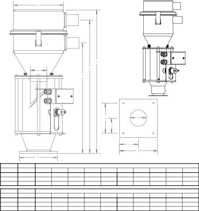
Figure 1: SRI Series Stainless Steel Inventory Vacuum Receiver Dimensions
SRI01 Vacuum Receiver
D |
|
|
|
A |
|
E |
B |
|
C |
||
|
SRI01.DWG
|
|
|
|
|
|
I |
|
J |
|
|
|
|
|
|
|
|
|
H |
|
|
|
|
|
|
|
|
|
|
|
|
G |
F |
|
|
|
|
|
F |
|
|
|
|
|
|
|
|
|
|
|
HOPSRI.DWG |
|
|
|
|
|
|
|
||
|
Unit size |
|
|
|
|
Dimensions in inches |
|
|
|
|
|
Model |
cu. ft. |
A |
B |
C |
D |
E |
F -sq. |
G -sq. |
H -sq. |
I -sq. |
J |
SRI01 |
0.1 |
211/4” |
20” |
165/8” |
63/8” |
13/4” |
4” |
2” |
11/4” |
21/2” |
2” |
SRI02 |
0.2 |
255/8” |
233/4” |
191/2” |
91/8” |
3” |
7” |
31/2” |
23/4” |
51/2” |
3” |
SRI04 |
0.4 |
311/2” |
295/8” |
251/2” |
91/8” |
3” |
7” |
31/2” |
23/4” |
51/2” |
3” |
|
Unit size |
|
|
|
|
Dimensions in cm |
|
|
|
|
|
Model |
liters |
A |
B |
C |
D |
E |
F -sq. |
G -sq. |
H -sq. |
I -sq. |
J |
SRI01 |
2.8 |
54.0 cm |
50.8 cm |
42.2 cm |
16.2 cm |
4.4 cm |
10.2 cm |
5.1 cm |
3.2 cm |
6.4 cm |
5.1 cm |
SRI02 |
5.6 |
65.1 cm |
60.3 cm |
49.5 cm |
23.2 cm |
7.6 cm |
17.8 cm |
8.9 cm |
6.9 cm |
13.9 cm |
7.6 cm |
SRI04 |
11.3 |
80.0 cm |
75.2 cm |
64.8 cm |
23.2 cm |
7.6 cm |
17.8 cm |
8.9 cm |
6.9 cm |
13.9 cm |
7.6 cm |
99/32”/0.28125” (7.14 mm) -diameter holes in four (4) places, equally spaced.
Conveying System Mechanical Components Chapter 2: Functional Description |
17 of 136 |
Pumps
VTP Series Models: VTP5, VTP7.5, VTP10, VTP15, VTP20, VTP30
•Support base.
•Positive displacement blower.
•3-phase high efficiency TEFC electric motor.
•5, 7.5, 10, 15, 20 or 30 horsepower (3.75, 5.63, 7.5, 11.25, 15 or 22.5 kW).
•Standard voltage is 230-460/3/60. 380-415/3/50 and 575/3/60 are optional.
•Adjustable motor base.
•Compressed air-operated mechanical high-vacuum relief valve.
•Vacuum gauge.
•Vacuum switch for high vacuum protection.
•Junction box with motor starter, including overload protection.
•Discharge silencer.
Options
•Fused disconnect in the junction box.
•Distributed I/O capability.
•Sound enclosure.
•Premium-efficiency motors.
•Re-sheave for elevation.
•24VDC or 120 AC controls.
Conveying System Mechanical Components Chapter 2: Functional Description |
18 of 136 |

Figure 2: VTP Series Pump Dimensions
C
A
|
|
|
|
|
|
|
|
E |
|
|
|
|
|
F |
|
|
|
|
|
|
B |
G |
|
|
|
|
D |
|
|
|
|
|
|
|
|
|
|
|
|
|
|
|
|
|
|
|
|
|
|
|
|
Model |
Unit size |
|
|
|
Dimensions (inches) |
|
|
|
||||
|
hp |
A |
B |
C |
|
D |
|
E |
F |
|
G |
|
VTP 5 |
5 |
20 |
42.5 |
47 |
|
25.75 |
|
|
39.5 |
23.5 |
47.5 |
|
VTP 7.5 |
7.5 |
21 |
42.5 |
50 |
|
25.75 |
|
|
39.5 |
23.5 |
48 |
|
VTP 10 |
10 |
21 |
56 |
50 |
|
25.75 |
|
|
53 |
31 |
48 |
|
VTP 15 |
15 |
25 |
56 |
62 |
|
32.5 |
|
|
53 |
31 |
57 |
|
VTP 20 |
20 |
32 |
56 |
65 |
|
32.5 |
|
|
53 |
31 |
60 |
|
VTP 30 |
30 |
38 |
50 |
85 |
|
37.25 |
|
|
48.25 |
35.75 |
69.3 |
|
|
|
|
|
|
|
|
|
|
|
|
|
|
Model |
Unit size |
|
|
|
Dimensions (cm) |
|
|
|
|
|||
|
KW |
A |
B |
C |
|
D |
|
E |
F |
|
G |
|
VTP 5 |
3.75 |
51 |
108 |
109 |
|
64 |
|
|
100 |
60 |
|
117 |
VTP 7.5 |
5.63 |
53 |
108 |
127 |
|
64 |
|
|
100 |
60 |
|
122 |
VTP 10 |
7.50 |
53 |
142 |
127 |
|
82 |
|
|
134 |
79 |
|
155 |
VTP 15 |
11.25 |
63 |
142 |
162 |
|
82 |
|
|
134 |
79 |
|
162 |
VTP 20 |
15.00 |
81 |
142 |
178 |
|
82 |
|
|
134 |
79 |
|
167 |
VTP 30 |
22.38 |
97 |
127 |
216 |
|
95 |
|
|
123 |
91 |
|
176 |
Conveying System Mechanical Components Chapter 2: Functional Description |
19 of 136 |
Blowback Pumps
VTPB Series Models: VTPB5, VTPB7.5, VTPB10, VTPB15, VTPB25, VTPB30
•Compressed air-operated blowback and vacuum valves with highvacuum relief.
•Mechanical high-vacuum relief valve.
•Support base.
•Positive displacement blower.
•Three (3) -phase high efficiency TEFC electric motor.
•5, 7.5, 10, 15, 25, or 30 horsepower (3.75, 5.63, 7.5, 11.25, 18.75, 22.5 kW)
•Standard 230-460/3/60. 380-415/3/50. 575/3/60 is optional.
•Adjustable motor base.
•Vacuum gauge.
•Vacuum switch for high vacuum protection.
•Junction box with motor starter, including overload protection.
•Discharge silencer.
Options
•Fused disconnect in the junction box.
•Distributed I/O capability.
•Sound enclosure.
•Efficiency motors available.
•Re-sheave for elevation.
•24VDC or 120VAC controls.
Conveying System Mechanical Components Chapter 2: Functional Description |
20 of 136 |

Figure 3: VTPB Series Blowback Pump Dimensions
A |
|
|
|
|
|
|
D |
|
|
|
|
|
|
|
|
|
|
|
|
|
|
|
|
|
|
B |
|
|
|
|
|
|
|
|
|
|
|
|
|
|
|
|
|
|
|
C |
|
|
|
|
|
|
|
|
|
|
|
|
|
|
|
|
|
H |
|
|
|
E |
|
|
|
|
|
|
I |
|
|
|
|
|
F |
|
|
|
|
|
|
|
|
|
|
|
|
|
|
|
|
|
|
J |
|
|
|
|
|
|
G |
|
|
|
|
|
|
|
|
|
|
|
|
|
|
|
|
|
|
K |
|
|
|
|
|
|
|
|
|
|
|
|
|
|
|
|
Model |
Unit size |
|
|
|
|
Dimensions (inches) |
|
|
|
|
||
|
hp |
A |
B |
C |
D |
E |
F |
G |
H |
I |
J |
K |
VTP 5 |
5 |
40 |
35 |
24 |
42.5 |
29 |
34 |
44 |
7 |
22.5 |
27.5 |
29 |
VTP 7.5 |
7.5 |
40 |
35 |
24 |
42.5 |
29 |
34 |
44 |
7 |
22.5 |
27.5 |
29 |
VTP 10 |
10 |
40 |
35 |
24 |
42.5 |
29 |
34 |
44 |
7 |
22.5 |
27.5 |
29 |
VTP 15 |
15 |
40 |
35 |
24 |
42.5 |
29 |
34 |
44 |
7 |
22.5 |
27.5 |
29 |
VTP 25 |
25 |
80 |
60 |
39 |
74 |
42.5 |
46 |
65 |
9 |
31.5 |
35 |
32 |
VTP 30 |
30 |
80 |
60 |
39 |
74 |
42.5 |
46 |
65 |
9 |
31.5 |
35 |
32 |
Model |
Unit size |
|
|
|
|
Dimensions (cm) |
|
|
|
|
||
|
kW |
A |
B |
C |
D |
E |
F |
G |
H |
I |
J |
K |
VTP 5 |
3.75 |
101 |
89 |
61 |
108 |
73 |
86 |
111 |
18 |
57 |
70 |
73 |
VTP 7.5 |
5.63 |
101 |
89 |
61 |
108 |
73 |
86 |
111 |
18 |
57 |
70 |
73 |
VTP 10 |
7.50 |
101 |
89 |
61 |
108 |
73 |
86 |
111 |
18 |
57 |
70 |
73 |
VTP 15 |
11.25 |
101 |
89 |
61 |
108 |
73 |
86 |
111 |
18 |
57 |
70 |
73 |
VTP 25 |
18.75 |
203 |
152 |
101 |
188 |
108 |
117 |
166 |
23 |
80 |
89 |
81 |
VTP 30 |
22.50 |
203 |
152 |
101 |
188 |
108 |
117 |
166 |
23 |
80 |
89 |
81 |
Conveying System Mechanical Components Chapter 2: Functional Description |
21 of 136 |
VTTV TurboVac Series Pumps
Models: VTTV-1.0, VTTV-2.0, VTTV-3.5, VTTV-8.5
•Centrifugal blower.
•Cartridge filter.
•Vent valve (optional on VTTV-1.0 1-hp [0.75 kW] unit).
•Junction box with starter mounted on unit.
Options
•Freestanding central filter.
•Distributed I/O.
•Fused disconnect.
•24VDC or 120VAC controls.
Conveying System Mechanical Components Chapter 2: Functional Description |
22 of 136 |
Figure 4: VTTV TurboVac Series Pump Dimensions
A
B
|
|
I |
|
|
F |
|
E |
|
|
D |
|
C |
G |
C |
|
H |
|
Model |
Unit size |
|
|
|
|
Dimensions (inches) |
|
|
|
||
|
hp |
A |
B |
C |
D |
|
E |
F |
G |
H |
I |
VTTV 1.0 |
1 |
9 |
123/8 |
9 |
— |
|
181/4 |
— |
163/4 |
261/4 |
23 |
VTTV 2.0 |
2 |
18 |
— |
18 |
205/8 |
|
253/8 |
2913/16 |
227/8 |
322/3 |
325/16 |
VTTV 3.5 |
3.5 |
18 |
— |
18 |
221/2 |
|
253/8 |
2913/16 |
227/8 |
355/16 |
325/16 |
VTTV 8.5 |
8.5 |
18 |
21 |
18 |
221/2 |
|
253/8 |
313/8 |
23 |
3713/16 |
337/8 |
Model |
Unit size |
|
|
|
|
Dimensions (cm) |
|
|
|
|
|
kW |
A |
B |
C |
D |
E |
F |
G |
H |
I |
VTTV 1.0 |
0.75 |
23 |
31 |
23 |
— |
46 |
— |
109 |
66 |
58 |
VTTV 2.0 |
1.50 |
46 |
— |
46 |
52 |
64 |
76 |
58 |
83 |
82 |
VTTV 3.5 |
2.63 |
46 |
— |
46 |
57 |
64 |
76 |
58 |
89 |
82 |
VTTV 8.5 |
6.38 |
46 |
53 |
46 |
57 |
64 |
79 |
58 |
96 |
86 |
Does not include D and F dimensions.
Dimension I is overall height for 1-hp (0.75 kW) unit only.Note: Atmospheric valve (shown) for TV 2.0 – 8.5 units only.
Conveying System Mechanical Components Chapter 2: Functional Description |
23 of 136 |
Figure 5: Pump Specifications (VTP, VTPB, and VTTV Pumps)
Model |
Amp draw, full-load amps |
Air flow |
Line size |
Ship weight |
||
hp |
230 V |
460 V |
575 V |
cfm |
inches |
lbs. |
PumpsVTP |
Models |
|
|
|
|
|
5 |
13.6 |
6.8 |
5.4 |
110 |
2” tube |
385 |
7.5 |
20.6 |
10.3 |
8.2 |
150 |
2½” tube |
470 |
10 |
27.2 |
13.6 |
10.9 |
225 |
3” tube |
830 |
15 |
39.2 |
19.6 |
15.7 |
350 |
3” Sch. 5 pipe |
870 |
20 |
49.6 |
24.8 |
19.8 |
449 |
4” Sch. 10 pipe |
1,600 |
30 |
76.3 |
38.1 |
30.4 |
646 |
5” tube |
1,700 |
Pumps with Blowback — VTPB Models |
|
|
|
|||
5 |
13.6 |
6.8 |
5.4 |
103 |
2” tube |
385 |
7.5 |
20.6 |
10.3 |
8.2 |
150 |
2½” tube |
470 |
10 |
27.2 |
13.6 |
10.9 |
225 |
3” tube |
830 |
15 |
39.2 |
19.6 |
15.7 |
300 |
3” Sch. 5 pipe |
870 |
25 |
63.0 |
24.8 |
25.1 |
545 |
4” Sch. 10 pipe |
1,600 |
30 |
76.2 |
38.1 |
30.4 |
765 |
5” Sch. 10 pipe |
1,800 |
TurboVac Pumps — VTTV Models |
|
|
|
|
||
1.0 |
3.4 |
1.7 |
1.4 |
50 |
1½” tube |
50 |
2.0 |
6.2 |
3.1 |
2.5 |
85 |
1½” tube |
75 |
3.5 |
11.3 |
5.7 |
4.4 |
100 |
2” tube |
175 |
8.5 |
23.8 |
11.9 |
9.2 |
225 |
3” tube |
350 |
Model |
Amp draw, full-load amps |
Air flow |
Line size |
Ship weight |
||
kW |
230 V |
460 V |
575 V |
cmh |
mm |
Kg |
PumpsVTP |
Models |
|
|
|
|
|
3.75 |
13.6 |
6.8 |
5.4 |
186 |
50 mm tube |
175 |
5.63 |
20.6 |
10.3 |
8.2 |
254 |
63 mm tube |
214 |
7.50 |
27.2 |
13.6 |
10.9 |
382 |
76 mm tube |
377 |
11.25 |
39.2 |
19.6 |
15.7 |
594 |
3” Sch. 5 pipe |
395 |
15.00 |
49.6 |
24.8 |
19.8 |
762 |
4” Sch. 10 pipe |
727 |
22.4 |
76.3 |
38.1 |
30.4 |
1,097 |
127 mm tube |
789 |
Pumps with Blowback — VTPB Models |
|
|
|
|||
3.75 |
13.6 |
6.8 |
5.4 |
175 |
50 mm tube |
175 |
5.63 |
20.6 |
10.3 |
8.2 |
254 |
63 mm tube |
214 |
7.50 |
27.2 |
13.6 |
10.9 |
382 |
76 mm tube |
377 |
11.25 |
39.2 |
19.6 |
15.7 |
507 |
3” Sch. 5 pipe |
395 |
18.75 |
63.0 |
24.8 |
25.1 |
920 |
4” Sch. 10 pipe |
727 |
22.50 |
76.2 |
38.1 |
30.4 |
1,290 |
5” Sch. 10 pipe |
818 |
TurboVac Pumps — VTTV Models |
|
|
|
|
||
0.75 |
3.4 |
1.7 |
1.4 |
84 |
38 mm tube |
23 |
1.50 |
6.2 |
3.1 |
2.5 |
144 |
50 mm tube |
35 |
2.63 |
11.3 |
5.7 |
4.4 |
169 |
50 mm tube |
80 |
6.38 |
23.8 |
11.9 |
9.2 |
382 |
76 mm tube |
159 |
Air flow measured in cubic feet per minute (cfm) and cubic meters per hour (cmh).
Note: Rated performance is at standard atmosphere and sea level conditions. High elevation affects system performance.
Conveying System Mechanical Components Chapter 2: Functional Description |
24 of 136 |

Figure 6: Positive Displacement Pump Dimensions
Model |
Unit size |
|
|
Dimensions (inches) |
|
|
|
||
|
hp |
A |
B |
C |
D |
|
E |
F |
G |
APD 5 |
5 |
33 |
27.5 |
85.82 |
29 |
|
22 |
21.75 |
31.75 |
APD 10 |
10 |
|
|||||||
APD 15 |
15 |
|
|
|
|
|
|
|
|
Model |
Unit size |
|
|
|
Dimensions (cm) |
|
|
|
||
|
kW |
A |
B |
C |
|
D |
|
E |
F |
G |
APD 5 |
3.75 |
84 |
70 |
218 |
|
74 |
|
56 |
55 |
81 |
APD 10 |
7.5 |
|
|
|||||||
APD 15 |
11.25 |
|
|
|
|
|
|
|
|
|
Conveying System Mechanical Components Chapter 2: Functional Description |
25 of 136 |

APC Centrifugal Pumps
Models: 3.5, 6.5 & 11 Hp
•Centrifugal blower.
•Cartridge filter.
•Vent valve
•Junction box with starter mounted on unit.
Figure 7: Centrifugal Pump Dimensions
Model |
Unit size |
|
|
|
Dimensions (inches) |
|
|
|
||
|
Hp* |
A |
B |
C |
D |
E |
F |
G |
H |
I |
APC 3.5 |
3.5 |
15 |
26.25 |
17.4 |
13 |
12 |
8.75 |
17.75 |
35 |
18 |
APC 6.5 |
6.5 |
24.5 |
13 |
7.5 |
31 |
17.75 |
||||
APC 11.5 |
11.0 |
|
31.5 |
|
14.8 |
|
8.6 |
|
35.5 |
19 |
Model |
Unit size |
|
|
|
|
Dimensions (cm) |
|
|
|
||
|
kW |
A |
B |
C |
D |
|
E |
F |
G |
H |
I |
APC 3.5 |
2.63 |
38 |
67 |
44 |
33 |
|
30 |
22 |
45 |
89 |
46 |
APC 6.5 |
4.84 |
62 |
33 |
|
19 |
79 |
45 |
||||
APC 11.0 |
8.58 |
|
80 |
|
37 |
|
|
21 |
|
90 |
48 |
*At 460/3/60
Conveying System Mechanical Components Chapter 2: Functional Description |
26 of 136 |
Figure 8: APD and APC Pump Specifications (Positive Displacement and Centrifugal pumps)
Model |
Amp draw, full-load amps |
Air flow |
Line size |
Ship weight |
|||||
hp |
230 V |
|
460 V |
|
575 V |
cfm |
inches |
lbs. |
|
Pumps — Positive Displacement Models |
|
|
Vacuum |
Material |
|
||||
5 |
13.4 |
|
6.7 |
|
5.4 |
120 |
2.0” |
2.0” |
385 |
10 |
28.4 |
|
14.2 |
|
11.4 |
200 |
2.5” |
2.5” |
400 |
10 |
29.2 |
|
14.6 |
|
11.7 |
300 |
3.0” |
3.0” |
400 |
15 |
38.4 |
|
19.2 |
|
15.3 |
300 |
3.0” |
3.0” |
420 |
15 |
39.2 |
|
19.6 |
|
15.7 |
360 |
3.5” |
3.5” |
420 |
Pumps — Centrifugal Models |
|
|
|
|
Vacuum |
Material |
|
||
3.5 |
9.1 |
|
4.6 |
|
3.0 |
106 |
2.0” |
1.5” |
175 |
6.5 |
12.9 |
|
6.5 |
|
4.3 |
152 |
2.0” |
2.0” |
300 |
11 |
32.5 |
|
16.2 |
|
10.6 |
225 |
2.5” |
2.5” |
350 |
Model |
Amp draw, full-load amps |
Air flow |
Line size |
Ship weight |
|||||
kW |
|
230 V |
|
460 V |
|
575 V |
cmh |
mm |
Kg |
Pumps — |
Positive |
Displacement Models |
|
|
|
|
|||
3.75 |
|
13.4 |
|
6.7 |
|
5.4 |
204 |
50 mm |
175 |
7.5 |
|
28.4 |
|
14.2 |
|
11.4 |
340 |
63 mm |
181 |
11.25 |
|
38.4 |
|
19.2 |
|
15.3 |
510 |
76 mm |
190 |
Pumps — |
Centrifugal Models |
|
|
|
|
|
|
||
3.5 |
|
9.1 |
|
4.6 |
|
3.0 |
180 |
38 mm |
80 |
6.5 |
|
12.9 |
|
6.5 |
|
4.3 |
258 |
50 mm |
136 |
11 |
|
32.5 |
|
16.2 |
|
10.6 |
302 |
63 mm |
159 |
Air flow measured in cubic feet per minute (cfm) and cubic meters per hour (cmh).
Rated performance is at standard atmosphere and sea level conditions. High elevation affects system performance
Conveying System Mechanical Components Chapter 2: Functional Description |
27 of 136 |
SRH/SRC Vacuum Receivers
Models: SRH01, SRC02, SRC04, SRC08, SRC16, SRC30, SRC60
•Receiver capacities of 0.1, 0.2, 0.4. 0.8, 1.6, 3.0, and 6.0 cu. ft. (2.8, 5.6, 11.3, 22.6, 45.3, 84.9, and 169.9 liters).
•Brushed stainless steel construction, with stainless steel product contact surfaces.
•Material demand/level sensor with Normally Open (std.) or Normally Closed (version available) contacts.
•Perforated stainless steel pellet deflectors (SRC30/60 Models).
•Ten (10) -mesh stainless steel pellet deflector screen (SRC02–16 models only).
•Removable side inlets and outlets – up to 3” O.D.(except on 0.1 cu. ft. [2.8 liter] models).
•Internal check valve on material inlets (up to 3” line size) – Not on SRC02 models.
Options
•Volume fill sensor.
•Optiview sensor.
•Spun aluminum riser.
•Filters (polyester and nylon).
•Throat gaskets – high temp & food grade.
•Consult assembly drawings for optional materials.
Note: SRC30/60 models can be vented or non-vented or equipped with a silo mount riser with an access door.
Conveying System Mechanical Components Chapter 2: Functional Description |
28 of 136 |
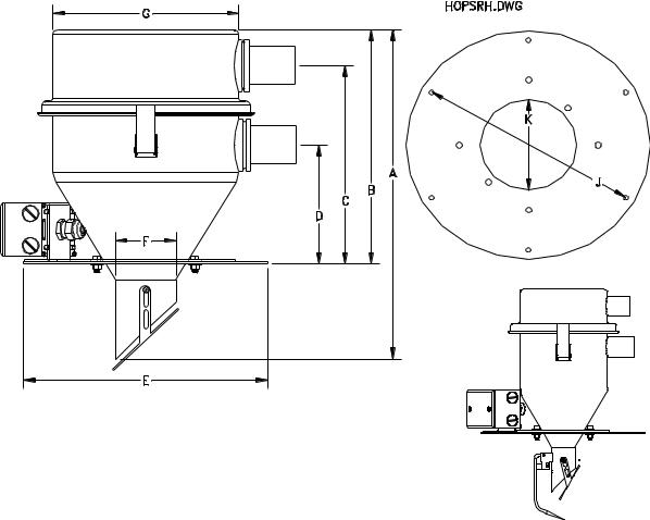
Figure 9: SRH Series Stainless Steel Vacuum Receiver Dimensions
H
SRH01 Vacuum Receiver
SRH01.DWG
Model |
|
Cu. ft. |
|
|
|
|
|
|
|
|
Dimensions (inches) |
|
|
|
|
|||||
|
|
A |
|
B |
|
C |
|
D |
|
|
E |
|
F |
|
G |
H |
J |
K |
||
SRH01 |
0.1 |
|
14.88” |
|
10.63” |
|
9.38” |
|
6.38” |
|
|
12” |
|
1.75” |
|
6.38” |
5.50” |
11” |
6.75” |
|
|
|
|
|
|
|
|
|
|
|
|
|
|
|
|
|
|
|
|
||
|
|
|
|
|
|
|
|
|
|
|
|
|
Dimensions (cm) |
|
|
|
|
|||
Model |
|
Liters |
|
|
|
|
|
|
|
|
|
|
|
|
|
|
|
|
|
|
|
|
A |
|
B |
|
C |
|
D |
|
|
E |
|
F |
G |
H |
J |
K |
|||
SRH01 |
|
2.8 |
|
38 |
|
27 |
|
24 |
|
16 |
|
|
31 |
|
4.4 |
|
16.2 |
14 |
28 |
17 |
5/16”/0.3125” (8.00 mm) -diameter holes, two (2) places equally spaced.
1/4”/0.2500” (6.35 mm) -diameter holes, six (6) places equally spaced; H is standard mounting hole location.
Conveying System Mechanical Components Chapter 2: Functional Description |
29 of 136 |
Loading...