

• STUDIO RIBBON MICS
Audio Engineering
Associates
“Tools to make Great Recordings Easier”
• PHASE DISPLAYS
• M/S STEREO
• TALL STANDS
• MIC POSITIONERS
MS38-MKII
Quickstart Manual
Basics
The AEA MS38-MKII is a line-lev el, dual mode, Mid/Side Matrix processor . It is intended for use in
the “insertion loop” of your mixing console or between two line-level pieces of equipment. Please use
caution NOT to connect the outputs of this unit to “phantom po wered” microphone inputs in your mixing
console, as this will damage the output drivers.
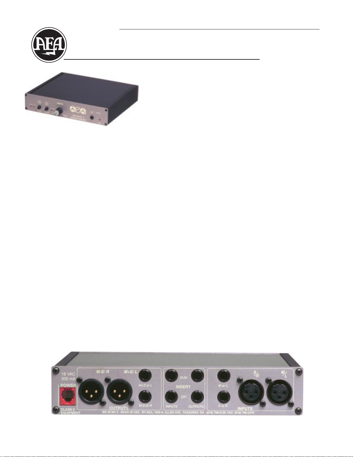
The Rear Panel
Beginning at the far right are the INPUT connectors; these are balanced and line-level. There are two
for each channel: an XLR-3F(pin-2 high) and a three-circuit (TRS tip-high) 1/4" phone jack, wired in
parallel for flexibility . Depending on the Mode you are using, these accept either the conv entional stereo
Left and Right signals or the Mid and Side component signals.
In the middle of the panel are the INSER T jacks. Also balanced and line-le vel, these 1/4" phone jacks
present Send and Return insert patchpoints for the Sum (Mid) and Difference (Side) signal paths. When
no connectors are inserted, the Returns are half-normalled from the Sends.
Next to the left are the OUTPUT connectors. Like the inputs, a parallel set of XLR-3M and 1/4" phone
jacks, balanced and line-level, is provided for each channel. They are designated as Left and Right or
M+S (Mid plus Side) and M-S (Mid minus Side), depending on the Mode of operation.
Finally , at the far left is the power supply connector . Just plug in the pro vided A C external transformer
and you’re ready to go.
1029 N. Allen Ave., Pasadena, CA 91104 www.wesdooley.com Phone: (626) 798-9128 Fax: (626) 798-2378
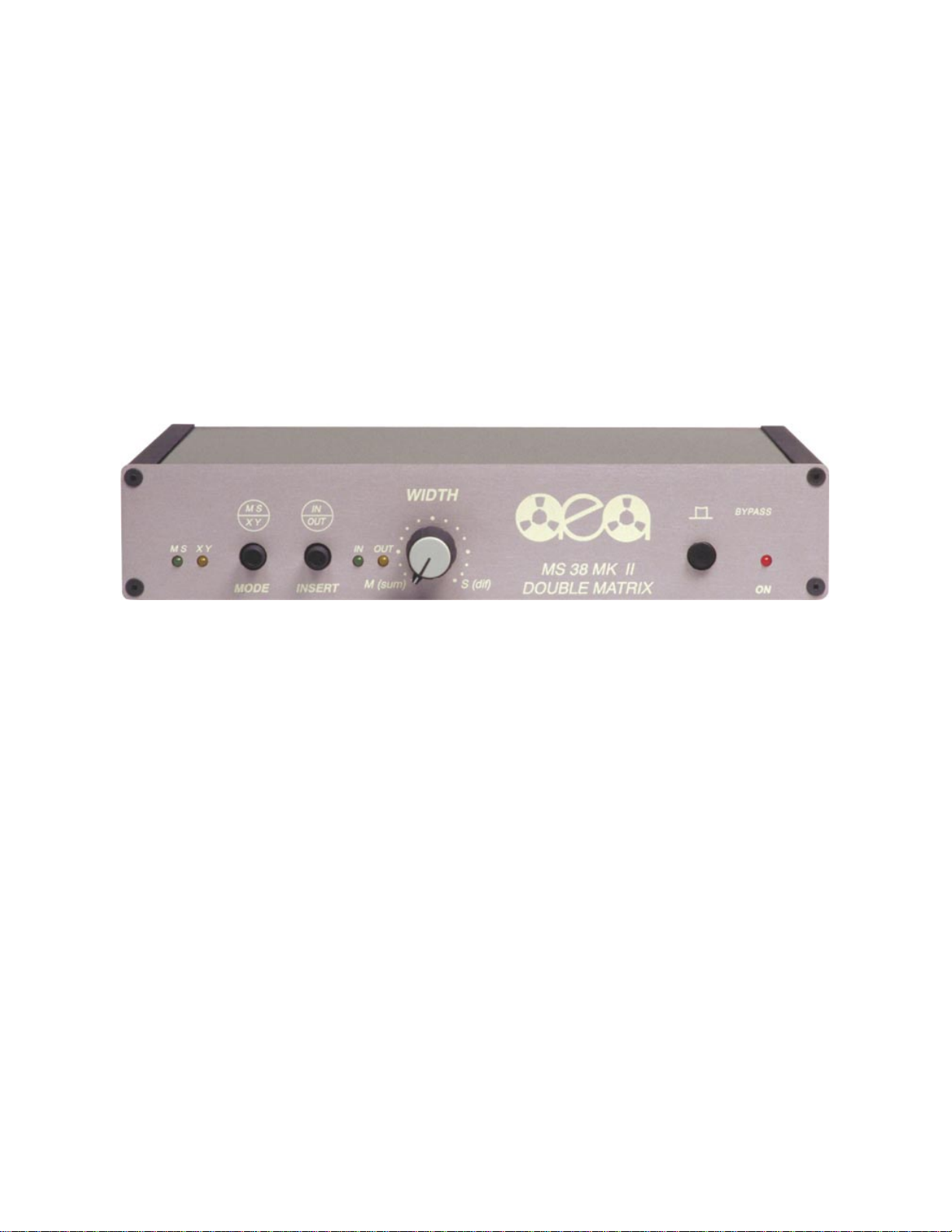
The Front Panel
Starting at the far left, the two LED’ s indicate the setting of the adjacent MODE pushbutton.
• When the button is out the unit is in the stereo, or XY mode. In this mode, normal Left and Right
stereo signals at the inputs are first converted to their Sum and Difference components and then
processed through the MS Matrix.
• When the button is depressed the unit is in the con v entional MS mode. In this mode, component Mid
and Side (or Sum and Difference) signals at the inputs are send to the MS Matrix for processing.
The status of the INSER T pushbutton is indicated by its two adjacent LED’s. When this button is out
the input signals proceed directly to the MS Matrix for processing. When the button is in the input signals
are first routed through any external signal processing connected via the Insert jacks on the rear panel.
It is important to remember that any signal processing accomplished via the insert patch points will
affect the signals prior to entering the MS Matrix and will therefore be represented at the outputs, in
either Mode of operation.
The WIDTH control represents the heart of the MS Matrix processing: It is via this knob that the stereo
width of the input signals can be manipulated.
• In the XY or Stereo Mode, when the knob is fully counter-clockwise, the output of both channels is
the monophonic sum of the two input signals. When the knob is fully clockwise, the output of both
channels is a monophonic signal, out-of-phase between the two channels, representing the difference
between the two input signals. Between these two extremes, any degree of stereo width can be selected
by rotating the knob: more mono to the left, more stereo separation to the right.
• In the MS Mode when the knob is fully counter-clockwise, the output of both channels is simply a
monophonic signal, representing the MID signal. When fully clockwise, the output at both channels is
again a monophonic signal, representing the SIDE signal, equal in amplitude but out-of-phase between
the two channels. As before, between these two extremes an y degree of stereo width can be selected
simply by rotating the knob: more mono to the left, more separation to the right. (The M+S output
represents the Sum of the input signals and the M-S output represents the Difference. When inputting
component Mid and Side signals, the M+S output will be the stereo channel represented by the positive
lobe of the Side microphone signal.)
To the right of the logo is the BYPASS pushb utton. When this button is in (the normal setting) the
signals at the input pass through the MS38-MkII with all the processing you select. When the button is
out there is a hard-wired bypass of all the circuitry , and inputs are routed directly to the outputs. This
is useful for quick A/B comparisons and also allo ws for the MS38-MkII to be left patched in the signal
chain even when not being used.
 Loading...