

Page 1

Page 2

OPERATING MANUAL
MODEL PK-88 PACKET CONTROLLER
ADVANCED ELECTRONIC APPLICATIONS, INC.
Rev. D 3/90
PROPRIETARY INFORMATION
Reproduction, dissemination or use of information contained herein for purposes other than operation and/or maintenance is prohibited without written authorization from Advanced Electronic Applications, Inc.
Page 3

Getting Started with the PK-88
Congratulations and thank you for your purchase of the AEA PK-88 Packet Data Controller. The following is intended to help get you started and "on the air" with the PK-88 quickly and easily.
The PK-88 operating Manual is filled with complete information on all commands and operating
modes. This doesn't mean you have to read it cover to cover before using your PK-88. Most of the
information you will need to connect your computer or terminal and radio to the PK-88 can be
found in Chapter 2 of the PK-88 Operating Manual.
If you are using one of our programs such as PC-Pakratt or PK-FAX for the IBM-PC and compatibles, COM-PAKRATT for the Commodore 64 and 128 or MacRATT for the Macintosh, then you
should start with the Installation section of the Program manual. After you have the program installed and running on your computer, then Chapter 2 of the PK-88 Operating Manual will describe
how to connect the PK-88 to your computer and transceiver.
AEA's programs such as PC-Pakratt simplify the way you enter commands to the PK-88. This
means that some of the sections of the PK-88 Manual that tell you to enter a command in a certain
manner will not apply. When using one of our programs on your computer, sections 2.5, 2.6 and
2.7 of the manual can be skipped.
In general, if you are using one of AEA's programs such as PC-Pakratt, PK-FAX, COM-PAKRATT, or
MacRATT, the manual that comes with the program should answer most questions. The PK-88 Operating Manual should only be needed as a reference when specific Hardware or Command information is sought.
On the other hand, if you are using a Dedicated Terminal or Terminal Program on your computer,
you should carefully follow the set-up procedure outlined in all of Chapter 2 of the PK-88 Operating
Manual. Sections 2.11 and 2.12 of the Manual describe how to connect the PK-88 to several different kinds of computers which may be especially helpful.
You will not need any of this information to get your PK-88 up and running, but you may want to
skim through the Addendum for the latest information on the PK-88 operating firmware.
NOTE TO PC-Pakratt USERS:
In order to run the PK-88 with PC-Pakratt, your PC-Pakratt disk must contain a file
PCPAKRA87.CFG. Contact AEA at 206-775-7373 if you have any questions.
Page 4

PK-88 OPERATING MANUAL PREFACE
PREFACE TO THE PK-88 PACKET CONTROLLER MANUAL
Please read this preface in its entirety. It contains information about how to receive warranty service, the current software installed in your PK-88, our software update policy and how to get involved in the digital radio community.
RF Interference Information To User
This PK-88 has been certified under Subpart J of Part 15 of the FCC rules.
This equipment generates and uses radio frequency energy. If it is not installed and used properly,
that is, in strict accordance with AEA's instructions, it may cause interference to radio and TV reception. It has been type tested and has been found to comply with the limits of a Class B computing device in accordance with the specifications in Subpart J of Part 15 of the FCC rules, which are
designed to provide reasonable protection against such interference in a residential installation.
However, there is no guarantee that interference will not occur in a particular installation. If this
equipment does cause interference to radio or TV reception, which can be determined by turning
the PK-88 on and off, the user is encouraged to try and correct the interference using one or more
of the following measures:
Reorient the antenna of the device receiving interference.
Relocate the computer with respect to this device.
Plug the computer into a different outlet so the computer and the device are on different
branch circuits.
If necessary, the user should consult the dealer or an experienced radio/TV technician for additional suggestions. The user may find 'How to Identify and Resolve Radio-TV Interference Problems,' a
booklet prepared by the FCC, helpful.
PLEASE USE SHIELDED CABLE FOR ALL RS-232 CONNECTIONS
As part of our continuing program of product improvement, we reserve the right to make changes
in this product's specifications. Changes will be made periodically to the information in this document. These changes will be incorporated in new issues of this manual.
There may be technical inaccuracies or typographical errors in this document. Please address comments and corrections to AEA Incorporated, PO Box C2160, Lynnwood, WA 98036-0918. AEA reserves the right to incorporate and issue any information thus supplied in whatever manner it
deems suitable without incurring any obligations whatever.
FIRST ISSUE (MAY 1988)
I PK-88 - 4
Page 5

PK-88 OPERATING MANUAL PREFACE
INTRODUCTION
Welcome to the exciting world of digital Amateur Radio! You've joined the ranks of the fastest
growing mode in Amateur Radio since the FM repeater.
Your AEA PK-88 Packet Controller is the connection between your computer and radio. The PK-88
performs all the 'magic' of establishing data and text communications between your station, as
well as many other communication facilities equipped for digital communications.
With Packet-Radio you'll have a 'private channel' while sharing a frequency with other Packet stations; you'll be able to 'read the mail' from other Packet stations, log onto computer-based 'bulletin
board' or 'mailbox' systems, handle message traffic - in short, you're now equipped to enjoy the
advantages of digital communications and error-correcting radio techniques in your ham shack.
Your new AEA PK-88 is the heart of your digital radio station. The PK-88's system software is derived from the original TAPR TNC; it presents many of the advanced features of that design,
coupled with significant enhancements based on the experience gained by thousands of TAPRequipped amateur Packet stations worldwide.
This manual is your guide into the realm of Amateur Packet-Radio.
Join a Packet Club - Subscribe To Newsletters - Join a Voice Net.
Join a packet radio club - they exist in all states as of this writing. You might also subscribe to the
ARRL publication 'Gateway,' which describes all the 'goings on' in Packet-Radio, and to the TAPR
'Packet Status Register,' which describes the technically interesting happenings in the movement.
There are many voice nets on VHF and HF; they usually meet weekly. They are usually dedicated
to making the newcomer feel at home.
Acknowledgment
AEA, Inc. gratefully acknowledges the Tucson Amateur Packet Radio Corporation, Tucson, AZ, for
permission to include excerpts from their TNC-2 documentation in this manual, and to Mike Chepponis and Phil Karn for their specifications for the KISS code.
Norm Sternberg (W2JUP) and Barbara Argilo developed, wrote and edited this Operating Manual
on Tandy 1000SX computers with IBM's Displaywrite 3 V1.1 program. Bernd, DC7XJ, has transferred this manual to the pdf format in March 2016.
Our special thanks to Mike Lamb (N7ML), Dr. Alan Chandler (K6RFK), John Gates (N7BTI), Steve
Stuart (N6IA), Andy Madsen (KB7B), Joe Schimmel (W2HPM), Jeff Jacobsen (WA7MBL), Hank
Oredsen (W0RLI), Brian Riley (KA2BQE), Phil Karn (KA9Q) and Mike Chepponis (K3MC) for their
help.
AEA, Inc. dedicates itself to the advancement of digital radio communications.
II PK-88 - 5
Page 6

PK-88 OPERATING MANUAL TABLE OF CONTENTS
TABLE OF CONTENTS
Paragraph Page
CHAPTER 1 – INTRODUCTION
1.1 Introduction ......................................................................................... 1-1 14
1.1.1 Scope ................................................................................................ 1-1 14
1.1.2 General ............................................................................................. 1-1 14
1.1.3 Application ........................................................................................ 1-1 14
1.2 Specifications ....................................................................................... 1-1 14
1.2.1 Description ........................................................................................ 1-1 14
1.2.2 Modem Characteristics ........................................................................ 1-2 15
1.2.3 Processor System ............................................................................... 1-2 15
1.2.4 Input/Output Connections ................................................................... 1-2 15
1.2.5 Controls and Indicators ....................................................................... 1-2 15
1.2.6 General ............................................................................................. 1-3 16
1.3 System Components ............................................................................. 1-3 16
1.4 Input/Output Devices ............................................................................ 1-3 16
1.5 System Transmitter/Receiver Performance Requirements .......................... 1-3 16
CHAPTER 2 – INSTALLATION
2.1 Preliminary Information ......................................................................... 2-1 17
2.1.1 Equipment Required ........................................................................... 2-1 17
2.1.2 Precautions ........................................................................................ 2-1 17
2.2 Installation ........................................................................................... 2-1 17
2.2.1 Power Connections ............................................................................. 2-1 17
2.2.2 Radio Input and Output Connections ................................................... 2-2 18
2.2.3 Computer Connections ....................................................................... 2-2 18
2.3 Controls and Indicators ......................................................................... 2-3 19
2.4 Status LEDs .......................................................................................... 2-3 19
2.5 Serial Port Configuration ........................................................................ 2-3 19
2.6 Screen Displays .................................................................................... 2-3 19
2.6.1 Echoes .............................................................................................. 2-4 20
2.6.2 Line Feeds and Carriage Returns ......................................................... 2-4 20
2.6.3 Screen Width ..................................................................................... 2-4 20
2.6.4 Display Speeds ................................................................................... 2-4 20
2.7 System Setup and Verification ................................................................ 2-4 20
2.8 Radio Connections and Setup ................................................................. 2-6 22
2.8.1 PTT (Push-to-Talk) Configuration ......................................................... 2-7 23
2.8.2 Data Carrier Detect (DCD Pin 8) Jumper JP6 ........................................ 2-8 24
2.8.3 FM Installation and Adjustment ........................................................... 2-8 24
2.8.4 SSB Installation and Adjustment .......................................................... 2-9 25
2.9 Command List Displays .......................................................................... 2-11 27
2.9.1 Display Complete Command List .......................................................... 2-11 27
2.9.2 Display Partial Command Lists ............................................................. 2-12 28
2.9.3 Display Asynchronous Port Parameters ................................................. 2-12 28
2.9.4 Display Special Characters .................................................................. 2-13 29
2.9.5 Display Identification Parameters ......................................................... 2-13 29
2.9.6 Display Link Parameters ...................................................................... 2-14 30
2.9.7 Display Monitor Parameters ................................................................. 2-14 30
2.9.8 Display Timing Parameters .................................................................. 2-15 31
2.10 Immediate Commands ......................................................................... 2-15 31
TOC 1 PK-88 - 6
Page 7

PK-88 OPERATING MANUAL TABLE OF CONTENTS
Paragraph Page
2.10.1 Unlisted Commands .......................................................................... 2-15 31
2.11 Detailed Connections for Specific Computers ......................................... 2-16 32
2.11.1 Computers with Specific Serial Interfaces ........................................... 2-16 32
2.11.2 Commodore 64, 64C, 128, Vic 20 ....................................................... 2-16 32
2.11.3 IBM PCjr .......................................................................................... 2-16 32
2.11.4 Tandy Color Computer ...................................................................... 2-17 33
2.11.5 Tandy Model 100/102, Kyocera KC-85 and NEC 8201 ........................... 2-17 33
2.11.6 Other Computers with 25-pin RS-232-C Ports ..................................... 2-17 33
2.11.7 Other Computers with Non-standard Serial Ports ................................. 2-18 34
2.12 Terminal (Modem) Software for Specific Computers ............................... 2-18 34
2.12.1 Apple Macintosh ............................................................................... 2-18 34
2.12.2 Apple II, II+, IIE and IIC .................................................................. 2-18 34
2.12.3 Commodore 64, 64C, 128, Vic 20 ....................................................... 2-19 35
2.12.4 IBM PCjr .......................................................................................... 2-19 35
2.12.5 Tandy Color Computer ...................................................................... 2-19 35
2.12.6 Tandy Model 100/102, Kyocera KC-85 and NEC 8201 ........................... 2-19 35
2.12.7 IBM PCs, 'Clones' and True Compatibles ............................................. 2-19 35
2.13 PBBS, Electronic Mail and File Server Program Compatibility ................... 2-19 35
2.13.1 Data Carrier Detect (DCD) Requirements ............................................ 2-20 36
CHAPTER 3 – BASIC OPERATION
3.1 Exploring the PK-88 Program ................................................................. 3-1 37
3.2 LED Status and Mode Indicators ............................................................. 3-1 37
3.2.1 Status Indicator LEDs ......................................................................... 3-1 37
3.2 2 The DCD LED - Data Carrier Detect ..................................................... 3-1 37
3.2.3 LEDs at System Start .......................................................................... 3-1 37
3.3 Commands ........................................................................................... 3-1 37
3.3.1 Entering Commands ........................................................................... 3-2 38
3.3.2 Command Responses ......................................................................... 3-2 38
3.3.3 Error Messages .................................................................................. 3-2 38
3.3.4 Command Names ............................................................................... 3-3 39
3.3.5 Default Values .................................................................................... 3-3 39
3.3.6 Parameters, Arguments and Values ...................................................... 3-3 39
3.3.7 Using Commands Without Arguments .................................................. 3-5 41
3.4 Controller Messages .............................................................................. 3-5 41
3.4.1 General Messages .............................................................................. 3-6 42
3.4.2 Command Mode Error Messages .......................................................... 3-6 42
3.4.3 Link Status Messages ......................................................................... 3-8 44
3.5 Special Keyboard Control Codes.............................................................. 3-9 45
3.6 Clear String Command. ......................................................................... 3-10 46
3.7 Detailed Command Descriptions ............................................................. 3-10 46
3.8 General Operating Information ............................................................... 3-10 46
3.8.1 Formatting Commands ....................................................................... 3-10 46
3.8.1.1 Screen Line Length .......................................................................... 3-10 46
3.8.1.2 Monitor Echo ................................................................................... 3-10 46
3.8.1.3 Line Feed ........................................................................................ 3-10 46
3.8.1.4 Carriage Return ............................................................................... 3-10 46
3.8.1.5 Backspace and Delete ...................................................................... 3-11 47
3.9 Escape Functions .................................................................................. 3-11 47
3.10 Send Time of Day ............................................................................... 3-11 47
3.11 Clear Transmit Buffer ........................................................................... 3-11 47
TOC 2 PK-88 - 7
Page 8

PK-88 OPERATING MANUAL TABLE OF CONTENTS
Paragraph Page
CHAPTER 4 - OPERATING MODES
4.1 General Information .............................................................................. 4-1 48
4.1.1 Change Radio Link Data Rate .............................................................. 4-1 48
4.1.2 Station Identification .......................................................................... 4-2 49
4.1.2.1 MYCALL Required at System Start-up ................................................ 4-2 49
4.1.2.2 Substation Identifiers (SSIDs) ........................................................... 4-2 49
4.1.2.3 Automatic Identification ................................................................... 4-2 49
4.2 Set Up Loopback Test Circuit .................................................................. 4-2 49
4.2.1 'Connect' and 'Disconnect ................................................................... 4-3 50
4.2.2 LED Status and Mode Indicators .......................................................... 4-3 50
4.3 System Loopback Test Connection .......................................................... 4-3 50
4.3.1 Connect Message ............................................................................... 4-3 50
4.3.2 Send Packet Character ........................................................................ 4-4 51
4.3.3 Return to Command Mode .................................................................. 4-4 51
4.3.4 Return to Converse Mode .................................................................... 4-4 51
4.3.5 Terminate the Link - Disconnect .......................................................... 4-4 51
4.4 Your First Packet Communication ........................................................... 4-5 52
4.4.1 System Cable and Switch Check .......................................................... 4-5 52
4.4.2 Starting the Communication ................................................................ 4-5 52
4.4.3 What If? ............................................................................................ 4-6 53
4.5 Automatic Operation ............................................................................. 4-6 53
4.5.1 Beacon Operation ............................................................................... 4-6 53
4.5.2 Will You Accept Connections? .............................................................. 4-7 54
4.5.3 Are You Available to Chat? .................................................................. 4-8 55
4.5.4 Do You Want to Transmit? ................................................................... 4-8 55
4.6 Digipeater Details .................................................................................. 4-8 55
4.6.1 Are You a Digipeater? ......................................................................... 4-9 56
4.6.2 Do You Want to be a Digipeater? ......................................................... 4-10 57
4.7 Unsuccessful Connections and Retries ..................................................... 4-10 57
4.7.1 Retries While Connected ..................................................................... 4-11 58
4.8 Monitoring Activity on the Channel ......................................................... 4-11 58
4.8.1 Monitoring Other Stations ................................................................... 4-11 58
4.8.2 Monitoring Digipeaters - The MRPT Command ...................................... 4-12 59
4.8.3 Monitoring Other Stations While Connected .......................................... 4-12 59
4.9 Selective Monitoring .............................................................................. 4-13 60
4.9.1 The MFROM Command ....................................................................... 4-13 60
4.9.2 The MTO Command ........................................................................... 4-14 61
4.9.3 The MCON Command ......................................................................... 4-15 62
4.9.4 The MFILTER Command ..................................................................... 4-15 62
4.9.5 The MHEARD Monitor Buffer ............................................................... 4-15 62
4.9.6 MSTAMP The Monitor Time-Stamp Command ....................................... 4-16 63
4.9.7 DAYTIME Set the Real-Time Clock ....................................................... 4-16 63
4.10 Packet Formatting ............................................................................... 4-16 63
4.10.1 PACLEN - Long or Short? ................................................................... 4-17 64
4.10.2 Backspace and Delete ....................................................................... 4-17 64
4.10.3 Cancel Line ...................................................................................... 4-17 64
4.10.4 Redisplay ......................................................................................... 4-17 64
4.10.5 XON/XOFF, START/STOP - Display Flow Control .................................. 4-18 65
4.10.6 The PASS Character .......................................................................... 4-18 65
4.10.7 More Carriage Returns and Line Feeds ............................................... 4-18 65
4.11 Multiple Connections ........................................................................... 4-18 65
TOC 3 PK-88 - 8
Page 9

PK-88 OPERATING MANUAL TABLE OF CONTENTS
Paragraph Page
4.11.1 Default Multiple-Connect Conditions ................................................... 4-19 66
4.11.2 The USERS Command - Multiple-Connect Active ................................. 4-19 66
4.11.3 CHSWITCH Character Selection ......................................................... 4-19 66
4.11.4 The CHCALL Command - Display Multiple-Connect Call Signs ............... 4-19 66
4.11.5 The CHDOUBLE Command - Display Doubled Characters ..................... 4-19 66
4.11.6 General Hints on Multi-Connect Operation .......................................... 4-20 67
4.12 MailDrop Operation ............................................................................. 4-20 67
4.12.1 RAM Space for Message Storage ........................................................ 4-21 68
4.12.2 System Commands ........................................................................... 4-21 68
4.12.2.1 Start and Stop MailDrop Operation .................................................. 4-21 68
4.12.2.2 Local Logon and Verification ........................................................... 4-21 68
4.12.2.3 Monitor MailDrop Operation ............................................................ 4-22 69
4.12.3 Caller Prompt ................................................................................... 4-22 69
4.12.4 Caller and SysOp MailDrop Commands ............................................... 4-22 69
4.12.4.1 B (BYE) ......................................................................................... 4-23 70
4.12.4.2 K n (KILL n) .................................................................................. 4-23 70
4.12.4.3 L (LIST) ........................................................................................ 4-23 70
4.12.4.4 R n (READ n) ................................................................................ 4-23 70
4.12.4.5 S callsign (Send callsign) ................................................................ 4-23 70
4.12.5 Sample Session - The Caller's Point of View ........................................ 4-24 71
4.12.5.1 Connect and Logon ........................................................................ 4-24 71
4.12.5.2 LIST Messages .............................................................................. 4-24 71
4.12.5.3 READ Messages ............................................................................. 4-25 72
4.12.5.4 KILL Messages .............................................................................. 4-25 72
4.12.5.5 SEND Messages ............................................................................. 4-25 72
4.12.5.6 Other People's Messages ................................................................ 4-26 73
4.12.5.7 Multiple Message Commands .......................................................... 4-26 73
4.12.5.8 Incorrect Commands ...................................................................... 4-26 73
4.12.5.9 Sorry, Wrong Number! ................................................................... 4-27 74
4.12.5.10 Log Off and Disconnect ................................................................ 4-27 74
4.12.6 Sample Session - The MailDrop SysOp's Point of View ......................... 4-27 74
CHAPTER 5 - COMMAND SUMMARY
5.1 Introduction ......................................................................................... 5-1 76
5.1.1 Entering Commands ........................................................................... 5-1 76
5.1.2 Command Responses ......................................................................... 5-1 76
5.1.3 Error Messages .................................................................................. 5-1 76
5.2 Command List ...................................................................................... 5-2 77
5.2.1 Command Names ............................................................................... 5-2 77
5.2.2 Default Values .................................................................................... 5-3 78
5.3 Parameters, Arguments and Values: ....................................................... 5-3 78
5.3.1 Parameters ........................................................................................ 5-3 78
5.3.1.1 Boolean Parameters ......................................................................... 5-3 78
5.3.1.2 Numeric Parameters ........................................................................ 5-3 78
5.3.1.3 Text or String Parameters ................................................................. 5-4 79
5.3.2 Using Commands Arguments Without Arguments ................................. 5-5 80
5.4 Controller Messages .............................................................................. 5-5 80
5.4.1 General ............................................................................................. 5-5 80
5.4.2 Command Mode Error Messages .......................................................... 5-6 81
5.4.3 Link Status Messages ......................................................................... 5-8 83
5.5 Clear String Commands ......................................................................... 5-10 85
TOC 4 PK-88 - 9
Page 10

PK-88 OPERATING MANUAL TABLE OF CONTENTS
Paragraph Page
5.6 Specific Commands ............................................................................... 5-10 85
8BITCONV ........................................................................................ 5-11 86
ACRDISP .......................................................................................... 5-11 86
ACRPACK .......................................................................................... 5-11 86
ADDRESS ......................................................................................... 5-12 87
AFILTER ........................................................................................... 5-12 87
ALFDISP ........................................................................................... 5-12 87
ALFPACK .......................................................................................... 5-13 88
AWLEN ............................................................................................. 5-13 88
AX25L2V2 ......................................................................................... 5-13 88
AXDELAY .......................................................................................... 5-14 89
AXHANG ........................................................................................... 5-14 89
BBSMSGS ......................................................................................... 5-14 89
BEACON ........................................................................................... 5-15 90
BKONDEL ......................................................................................... 5-15 90
BTEXT .............................................................................................. 5-16 91
CALIBRATE ....................................................................................... 5-17 92
CANLINE .......................................................................................... 5-17 92
CANPAC ........................................................................................... 5-18 93
CASEDISP ........................................................................................ 5-18 93
CBELL .............................................................................................. 5-19 94
CFROM ............................................................................................. 5-19 94
CHCALL ............................................................................................ 5-20 95
CHDOUBLE ....................................................................................... 5-21 96
CHECK ............................................................................................. 5-21 96
CHSWITCH ....................................................................................... 5-22 97
CLKADJ ............................................................................................ 5-22 97
CMDTIME ......................................................................................... 5-23 98
CMSG ............................................................................................... 5-23 98
COMMAND ....................................................................................... 5-23 98
CONMODE ........................................................................................ 5-24 99
CONNECT ......................................................................................... 5-24 99
CONOK ............................................................................................ 5-25 100
CONPERM ........................................................................................ 5-25 100
CONSTAMP ....................................................................................... 5-26 101
CONVERSE ....................................................................................... 5-26 101
CPACTIME ........................................................................................ 5-26 101
CR ................................................................................................... 5-27 102
CSTATUS .......................................................................................... 5-27 102
CTEXT .............................................................................................. 5-28 103
DAYTIME .......................................................................................... 5-29 104
DAYSTAMP ....................................................................................... 5-30 105
DELETE ............................................................................................ 5-30 105
DFROM ............................................................................................ 5-30 105
DIGIPEAT ......................................................................................... 5-31 106
DISCONNE ....................................................................................... 5-31 106
DISPLAY ........................................................................................... 5-32 107
DWAIT ............................................................................................. 5-33 108
ECHO ............................................................................................... 5-33 108
ESCAPE ............................................................................................ 5-34 109
FLOW ............................................................................................... 5-34 109
FRACK .............................................................................................. 5-34 109
TOC 5 PK-88 - 10
Page 11

PK-88 OPERATING MANUAL TABLE OF CONTENTS
Paragraph Page
FULLDUP .......................................................................................... 5-35 110
HBAUD ............................................................................................. 5-35 110
HEADERLN ....................................................................................... 5-36 111
HELP ................................................................................................ 5-36 111
HID ................................................................................................. 5-36 111
HOST ............................................................................................... 5-37 112
HPOLL .............................................................................................. 5-37 112
ID .................................................................................................... 5-38 113
ILFPACK ........................................................................................... 5-38 113
IO .................................................................................................... 5-38 113
K ..................................................................................................... 5-38 113
KISS ................................................................................................ 5-39 114
MAILDROP ....................................................................................... 5-40 115
MAXFRAME ....................................................................................... 5-40 115
MBELL .............................................................................................. 5-41 116
MBX ................................................................................................. 5-42 117
MCON .............................................................................................. 5-43 118
MDCHECK ........................................................................................ 5-44 119
MDIGI .............................................................................................. 5-45 120
MDMON ........................................................................................... 5-45 120
MDPROMPT ...................................................................................... 5-45 120
MEMORY .......................................................................................... 5-46 121
MFILTER .......................................................................................... 5-46 121
MFROM ............................................................................................ 5-46 121
MHEARD .......................................................................................... 5-47 122
MONITOR ......................................................................................... 5-48 123
MONITOR ON/OFF ............................................................................ 5-49 124
MPROTO .......................................................................................... 5-49 124
MRPT ............................................................................................... 5-49 124
MSTAMP ........................................................................................... 5-50 125
MTO ................................................................................................ 5-50 125
MYALIAS .......................................................................................... 5-51 126
MYCALL ............................................................................................ 5-51 126
NEWMODE ....................................................................................... 5-52 127
NOMODE .......................................................................................... 5-52 127
NUCR ............................................................................................... 5-53 128
NULF ............................................................................................... 5-53 128
NULLS .............................................................................................. 5-53 128
PACLEN ............................................................................................ 5-54 129
PACTIME .......................................................................................... 5-54 129
PARITY ............................................................................................ 5-55 130
PASS ................................................................................................ 5-55 130
PASSALL ........................................................................................... 5-56 131
PERSIST ........................................................................................... 5-56 131
PPERSIST ......................................................................................... 5-57 132
RAWHDLC ........................................................................................ 5-57 132
REDISPLA ......................................................................................... 5-57 132
RELINK ............................................................................................ 5-58 133
RESET .............................................................................................. 5-58 133
RESPTIME ........................................................................................ 5-58 133
RESTART .......................................................................................... 5-59 134
RETRY ............................................................................................. 5-59 134
TOC 6 PK-88 - 11
Page 12

PK-88 OPERATING MANUAL TABLE OF CONTENTS
Paragraph Page
SENDPAC ......................................................................................... 5-59 134
SLOTTIME ........................................................................................ 5-60 135
SQUELCH ......................................................................................... 5-60 135
START .............................................................................................. 5-60 135
STOP ............................................................................................... 5-61 136
TBAUD ............................................................................................. 5-61 136
TCLEAR ............................................................................................ 5-61 136
TIME ................................................................................................ 5-61 136
TONE ............................................................................................... 5-62 137
TRACE ............................................................................................. 5-62 137
TRANS ............................................................................................. 5-63 138
TRFLOW ........................................................................................... 5-63 138
TRIES .............................................................................................. 5-64 139
TXDELAY .......................................................................................... 5-64 139
TXFLOW ........................................................................................... 5-64 139
UNPROTO ......................................................................................... 5-65 140
USERS ............................................................................................. 5-65 140
XFLOW ............................................................................................. 5-66 141
XMITOK ........................................................................................... 5-66 141
XOFF ............................................................................................... 5-66 141
XON ................................................................................................. 5-67 142
CHAPTER 6 -TROUBLESHOOTING
6.1 Introduction ......................................................................................... 6-1 143
6.2 General Tests ........................................................................................ 6-1 143
6.2.1 Power Supply ..................................................................................... 6-1 143
6.2.2 Obvious Problems .............................................................................. 6-2 144
6.2.3 Assembly Problems ............................................................................ 6-2 144
6.2.4 Cabling Problems ............................................................................... 6-2 144
6.3 Specific Symptoms ................................................................................ 6-2 144
6.3.1 Symptom: PK-88 appears dead ........................................................... 6-2 144
6.3.2 Symptom: Transmitter cannot be keyed ............................................... 6-4 146
6.3.3 Symptom: Transmitted signals not copyable by other stations................. 6-4 146
6.3.4 Symptom: Received signals not copyable ............................................. 6-4 146
6.4 Terminal Interface Troubleshooting ......................................................... 6-4 146
6.4.1 Symptom: PK-88 does not communicate with the terminal .................... 6-5 147
6.4.2 Symptom: PK-88 signs on with mutilated data ...................................... 6-5 147
6.4.3 Symptom: PK-88 does not respond or accept commands ....................... 6-6 148
TOC 7 PK-88 - 12
Page 13

PK-88 OPERATING MANUAL TABLE OF CONTENTS
Paragraph Page
APPENDICES
APPENDIX A – PK-88 COMMAND LIST SUMMARY ........................................... A 149
APPENDIX B – WARRANTY
APPENDIX C – TTL HEADER INSTALLATION INSTRUCTIONS ........................... C 152
APPENDIX D – SCHEMATIC DIAGRAM & PARTS PICTORIAL ............................ D 154
APPENDIX E – SPECIFIC RADIO CONNECTIONS ............................................. E 156
APPENDIX F – PK-88 REVISION SUPPLEMENT 16-MAY-89 ............................... F 159
APPENDIX G – COMMONLY ASKED QUESTIONS SPECIAL NOTES
TO AEA SOFTWARE USERS ..................................................... G 163
APPENDIX H – NET/ROM MODIFICATION ...................................................... H 168
APPENDIX I – LITHIUM BATTERY .................................................................. I 169
END 169
TOC 8 PK-88 - 13
Page 14

PK-88 OPERATING MANUAL INTRODUCTION
CHAPTER 1 – INTRODUCTION
1.1 Introduction
The PK-88 Operating Manual describes the general characteristics and operation of your PK88 Packet Controller. This Operating Manual will help you to install, adjust and operate your
system.
1.1.1 Scope
The Operating Manual provides detailed information on installation and operation of the
PK-88. The manual describes the PK-88's features, system components and basic operation on Packet Radio. Information on theory of operation, hardware and software descriptions, protocols and troubleshooting instructions is also available.
1.1.2 General
The PK-88 can be used with any standard communications terminal or computer equipped
with an RS-232C ASCII serial data port and an appropriate communications program or
terminal emulator. For information on operation with nonstandard interfaces or terminals,
please contact the manufacturer.
1.1.3 Application
The PK-88 Packet Controller is a digital link between your radio and your computer or terminal. The PK-88 provides all decoding, encoding and transmitter control routines needed
to send and receive Packet-Radio. You can use your computer or any ASCII data terminal
with the same communications program or terminal emulator that you use with a telephone line modem.
1.2 Specifications
As part of its program of product improvement, the manufacturer reserves the right to
change this product's specifications. Changes will be made to the information in this document and incorporated in revisions to this manual. Specifications are subject to change without notice.
1.2.1 Description
The Model PK-88 is an asynchronous PAD (Packet Assembler/Disassembler) or data controller that includes a built-in modem for Packet-Radio operation. The PK-88 hardware
HDLC system converts serial, asynchronous, ASCII data to the internationally accepted
AX.25 Packet-Radio protocol via an EIA standard RS-232 serial port. In addition, a Host
mode, raw HDLC and KISS ('Keep It Simple, Stupid') TNC protocols are available for applications other than AX-25 protocols.
Operating Modes: Packet-Radio per AX.25, half- or full-duplex.
MailDrop - personal mailbox system
Host Mode with Raw HDLC and KISS TNC protocol for service with
TCP/IP and specialized applications.
1 - 1 PK-88 - 14
Page 15

PK-88 OPERATING MANUAL INTRODUCTION
1.2.2 Modem Characteristics
Modulator/Demodulator: AMD 7910 'World Chip' modem.
Data format: Serial, asynchronous
Modem Tones: Bell 103 and Bell 202
Transmitter:
Modulation method: Binary, phase-coherent NRZI FSK
Frequency accuracy: Bell 202 (mark) ± 1 Hz
All others (mark) ± 0.4 Hz
Harmonics: 45 dB below fundamental, single tone
Receiver:
Demodulation method: Differential FM detection
Output Level: 5 to 100 millivolts RMS, adjustable by internal control
1.2.3 Processor System
Protocol conversion: Zilog Z-80 microprocessor
RAM: 32 kilobytes
ROM: Up to 48 kilobytes of ROM may be used
Hardware HDLC: Zilog 8530 SCC
1.2.4 Input/Output Connections
Radio Interface: Eight-pin microphone connector
Input/Output Lines Receive audio
External Modem Interface: Pins 13 through 17 of Connector J1
TTL Input/Output Lines Receive data (RXD)
Terminal Interface: Standard RS-232C 25-pin DB25 connector
Input/Output Lines RS-232C (CCITT V.24/V.28) with full handshake (hard-
Terminal Data Rates Auto-baud selection of 300, 1200, 2400, 4800, and
Transmit audio
Push-To-Talk (PTT)
External squelch input
Ground
Transmit data (TXD)
Transmit Clock (TXC)
Data Carrier Detect (DCD)
Ground
ware and software)
9600 BPS. TBAUD adds 45, 50, 57, 75, 100, 110, 150,
200, 600 and 19,200 BPS terminal rates.
1.2.5 Controls and Indicators
Front Panel Controls: Power Switch
Status and Mode Indicators: CONV, TRANS, CMD, SEND, DCD, STA, CON, MULT,
PWR
1 - 2 PK-88 - 15
Page 16

PK-88 OPERATING MANUAL INTRODUCTION
1.2.6 General
Power Requirements: +13 VDC (12 to 16 VDC) at 500 mA.
Internally fused, with reverse-polarity protection.
Mechanical: 7.5 inches by 6.05 inches by 1.5 inches
(19.05 mm by 15.4 mm by 3.8 mm)
Weight 2 pounds 5 ounces (1.05 kg)
Environmental:
Ambient Temperature: Operating: 0 °C to +55 °C
Storage: -40 °C to +60 °C
1.3 System Components
The PK-88 Packet Controller package contains the following items:
o One PK-88 Packet Controller
o Power cable with single 3.5-mm coaxial connector
o Operating Manual
o Two DIP Bypass Headers for TTL Serial Interface Compatibility
1.4 Input/Output Devices
The PK-88 can be used with any standard ASCII data terminal or computer equipped with
an RS-232C serial data port and a communications program or terminal emulator. Data and
control signals are exchanged between the PK-88 and the computer or terminal at standard
RS-232C (CCITT V.24/V.28) levels.
Your computer and terminal program and their associated tape, disk and printer I/O devices
provide the means to store messages received and retrieve messages for transmission.
Although highly desirable, these peripheral or I/O devices are not needed for PK-88 operation.
Note: In this Operating Manual, 'computer' and 'terminal' mean the same thing - the key-
board and monitor or printer with which you communicate with the PK-88.
1.5 System Transmitter/Receiver Performance Requirements
Most modern radio transceivers are capable of excellent Packet-Radio performance. Radio
switching and other delays can be compensated by parameter value adjustments to the PK-
88.
The PK-88 provides software-controlled timing variations that permit operation with almost
all HF and VHF/UHF radios in general use today.
1 - 3 PK-88 - 16
Page 17

PK-88 OPERATING MANUAL INSTALLATION
CHAPTER 2 – INSTALLATION
2.1 Preliminary Information
This section contains instructions for a 'generic' installation and system checkout to install
and verify the PK-88's operation with both VHF-FM and HF SSB radios.
2.1.1 Equipment Required
A complete PK-88 Packet Controller system consists of the PK-88 and a 12 to 16-volt DC
power supply, a computer, a terminal emulator or communication program for the computer, a radio transceiver or receiver-transmitter combination and its power supply.
Your PK-88 Packet Controller is furnished with the cables required for connection to your
radio and to an external power supply. You must add the microphone connector required
by your radio, the power supply and the RS-232 cable that connects the PK-88 to your
computer.
RAM battery backup is provided by two internal AA batteries. (user supplied and installed)
2.1.2 Precautions
We strongly recommend that all RS-232 cables and connectors be made with the best
commercial quality shielded materials, and that careful and correct grounding and bonding procedures be observed in the installation of the radio equipment being used with the
PK-88.
2.2 Installation
The following sections describe the connectors and their connections to your computer and
your radio.
2.2.1 Power Connections
Power is connected to the PK-88's rear-panel coaxial power receptacle from any well regulated 12-volt DC power supply (12 to 16 VDC) capable of supplying at least 600 milliamperes. An optional wall adapter power supply can be used.
o Be sure your power supply can furnish the required current with a ripple voltage of
less than one volt peak to peak.
o Be sure you connect the positive voltage to the center pin of the coaxial power
plug.
o Check the supplied cord to determine which lead is positive.
If you accidentally invert the power cable, an internal fuse will open to protect the PK-88
from reverse-voltage damage. Note that the 0.1 µF bypass capacitor C1 may be damaged.
If polarity reversal does occur, open the PK-88, replace the internal fuse and capacitor C1
with identical components.
2 - 1 PK-88 - 17
Page 18

PK-88 OPERATING MANUAL INSTALLATION
2.2.2 Radio Input and Output Connections (See Table 2-1)
We supply a shielded cable with your PK-88. You must supply and connect the plugs for
the cable ends. This cable connects your PK-88 to your radio's microphone receptacle or
PTT and phone patch/tone inputs.
NOTE: Wire only the PK-88 cable end at this time. Leave the "radio" end unwired.
You will use the radio cable in a test configuration during your first 'loopback'
experiments with Packet operation.
Four signals and ground pass between your PK-88 and your radio via eight-pin receptacle
P2. The pin wiring is shown in Table 2-1.
Pin 2.4 Signal Name Color 2.2.6 Description
1
Ground
3
Push-To-Talk
2
Microphone audio
8
Receive audio
7
Squelch input (Optional)
Brown
Red
White
Green
Black
Audio and PTT common return
PK-88 keys transmitter
AFSK from PK-88 to transmitter
AFSK from receiver to PK-88
Allows PK-88 to detect activity on a
shared-mode-channel (optional)
NOTE: The remaining pins are not connected.
Table 2-1 J2 Radio Port Connector
2.2.3 Computer Connections (See Table 2-2)
NOTE: The serial interface in the PK-88 comes from the factory configured for RS-
232C voltage levels. Please see Appendix B for the TTL header installation instructions if your computer does not support RS-232C.
The PK-88's rear-panel serial port connector carries data and control signals between your
computer and the PK-88. The PK-88 is connected to a computer just like you connect a
RS-232C modem. If you now use your computer with a modem, connect the PK-88 the
same way. Use any terminal program you now use with your modem. The minimum number of pins that must be connected is shown in Table 2-2.
NOTE: The following are the least number of wires you can use to connect the PK-
88 with a computer or terminal. This three-wire connection does not permit
hardware flow control. In this case, software flow control (XON-XOFF) must
be provided by the terminal program.
Pin Signal Name Description
2
Transmit Data
3
Receive Data
7
Signal Ground
Serial data from computer to PK-88
Serial data from PK-88 to computer
Common ground for both data lines
Table 2-2 Minimum Serial Port Connections Required by PK-88
2 - 2 PK-88 - 18
Page 19

PK-88 OPERATING MANUAL INSTALLATION
2.3 Controls and Indicators
The PK-88 has a single rear-panel control:
o POWER ON/OFF push switch - disconnects power from external supply.
2.4 Status LEDs
The PK-88's front panel has the following LED (Light Emitting Diode) indicators:
CONV System is in Converse Mode
TRANS System is in Transparent Mode
CMD System is in Command Mode
SEND Transmitter Push-to-Talk line is enabled
DCD Data Carrier Detect
STA Packet frame(s) unacknowledged
CON Packet link is in connected state
MULT Multiple Connection in progress
PWR Power On Indicator
2.5 Serial Port Configuration
Verify that the PK-88's serial port and data words are set up properly for your computer.
Should your monitor display garbled or incorrect characters or 'funny' graphic symbols, you
can change the PK-88's serial port parity and word length. The common parity and word
length combination is seven data bits, even parity, one stop bit.
Your computer will probably accept the PK-88's default setting, even if it actually uses a different setting. If your computer requires eight data bits, you may have to set parity to
'none'; otherwise text may be interpreted as graphics or other special characters.
To set eight bits, no parity, type:
AWLEN 8 (eight-bit words) PARITY 0 (no parity bit)
To return to seven bits, even parity, type:
AWLEN 7 (seven-bit words) PARITY 3 (even parity)
You must type the command RESTART for the settings to take effect. One of these combina-
tions will satisfy most computers. You are more likely to require a different setting if you
have a 'dumb' terminal rather than a computer, or if you have configured your computer's
serial port for some special application. If your computer needs odd parity, set PARITY to 1.
If you see framing errors, try this for shorter characters:
AWLEN 7 (seven-bit words) PARITY 0 (no parity bit)
2.6 Screen Displays
Some computers and terminal programs are configured to certain default characteristics that
may at first seem incompatible with the PK-88. Follow these hints as you begin to 'dialogue'
with your new TNC.
2 - 3 PK-88 - 19
Page 20

PK-88 OPERATING MANUAL INSTALLATION
2.6.1 Echoes
If you see two characters on your screen for each character you type, then your computer
and the PK-88 are echoing your typed characters.
cmd:RREESSEETT
o Type: ECHO OFF to stop the PK-88's echoes.
If you use the PK-88 later with a different terminal program, you may see nothing displayed when you type. In that case, set ECHO ON.
2.6.2 Line Feeds and Carriage Returns
If lines displayed appear to be double spaced, your computer is adding an extra line feed
<LF> when it displays a carriage return <CR>.
o Set ALFDISP OFF to stop the PK-88 from adding an <LF>.
If you change terminal equipment you may have to set ALFDISP ON to restore the PK-88's
automatic line feeds.
2.6.3 Screen Width
If ALFDISP is ON, the PK-88 sends an extra <CR>, or <CR><LF> to your terminal when
80 characters have been displayed on a line. The screen width default value is 80, the
width of most CRT displays.
If your computer does not automatically break long lines:
o Set ACRDISP (the screen width) to the width of your display.
o For a computer using a TV set for a display, set ACRDISP to 40.
If your computer does automatically break long lines:
o Set ACRDISP to 0 to disable this feature. Otherwise, you will get two<CR>s when
the line wraps around.
2.6.4 Display Speeds
A few computers or terminal programs may lose the first characters of a line when several
lines are displayed in rapid succession.
o Set NUCR ON (delay after <CR>), or NULF ON (delay after <LF>) to give the com-
puter more time between lines.
The delay is adjusted by NULLS, which sets the number of character times for the delay.
2.7 System Setup and Verification
DISCONNECT POWER BEFORE MAKING ANY OTHER CONNECTIONS!
Do these steps before connecting any cables between the PK-88 and your radio:
2 - 4 PK-88 - 20
Page 21

PK-88 OPERATING MANUAL INSTALLATION
1. Open the PK-88 and install 2 AA batteries in the Battery Holder.
2. Connect the PK-88 to your computer via the RS-232 cable.
3. Turn ON your computer. Load and run your communications program.
4. Connect the wired end of the shielded cable to J2 on your PK-88.
5. Connect the wires from the PK-88's J2 pins 2 and 8 to each other.
6. Connect the PK-88 to a regulated 12-volt DC power supply.
7. Press the PK-88's power switch to the ON position.
8. Set your computer's data rate to 1200 baud, 7 bits, even parity if possible. If your
serial port is operating at 1200 baud, you will see the following message right away:
Please type a star ( * ) for autobaud routine.
If this message appears, go to Step 10 now.
9. If you are using your computer or terminal at a different data rate, word length or
parity, your screen may show meaningless 'garbage' or mutilated characters, or
nothing at all. If true, go to Step 10 now.
(Don't worry! – the PK-88 is doing its 'auto-baud' routine. It measures your computer's data rate, digital word length, parity, and then sets itself accordingly. The
PK-88 automatically scans baud rates of 300, 1200, 2400, 4800 and 9600 baud.)
10. Type several asterisks (*) at intervals of one second.
If the cable and connections between the PK-88 and your computer are correct, the
MULT LED will be extinguished and other LEDs will be lit as the PK-88 does its 'autobaud' routine. As soon as the PK-88 has recognized your data rate and set itself to
your data rate, the CMD LED is lit and your screen displays the sign-on message
ending with the
cmd:
command prompt:
PK-88 is using default values.
AEA PK-88 Packet Controller
AX.25 Level 2 Version 2.0
Copyright (C) 1986, 1987, 1988 by
Advanced Electronic Applications, Inc.
Release xx.xxx.xx +
Checksum $xx
cmd:
NOTE: The Release date and checksum shown above will change as the PK-
88's firmware is revised or updated. Please note this Date and Checksum on the inside front cover of this manual.
11. Do not turn on your radio yet!
12. Type MY AAA followed by a [RETURN] (or [↵] key). Your monitor should display
cmd:
my aaa
MYCALL was PK88
MYCALL now AAA
2 - 5 PK-88 - 21
Page 22

PK-88 OPERATING MANUAL INSTALLATION
13. Type C AAA followed by a [RETURN]. After a few moments, your monitor should display:
cmd:
c aaa
*** CONNECTED to AAA
14. Type a few characters, any characters, followed by a [↵]. After a few moments,
your monitor should echo the same characters that you have just typed.
15. Type [^C] ) (type [C] while pressing the [CONTROL] key down). Your monitor
should respond with:
cmd:
16. Type HB 300 followed by a [RETURN]. Your monitor should respond with:
HBAUD was 1200
HBAUD now 300
17. Type [K] followed by a [RETURN]. Your monitor should echo the characters you've
just typed.
18. Type [^C]. Your monitor should respond with:
cmd:
19. Type [D] followed by a [↵]. Your monitor should respond with:
cmd:
d
*** DISCONNECTED: AAA
20. If you have done all these steps successfully, you have completed the system installation and you are ready to begin operating.
21. If you have problems with the steps shown above, return to Step 1 AFTER checking
all cables and connectors. Read each step again carefully. If you still have problems,
shut down the PK-88 and contact our Customer Service Department as suggested in
the front of this manual.
If all the front-panel LEDs remain lit at system start, verify that your power supply
can provide at least 600 ma. at 12 VDC.
2.8 Radio Connections and Setup
DISCONNECT ALL POWER BEFORE MAKING ANY OTHER CONNECTIONS!
Use this simple step-by-step routine to verify that all cables and connectors are properly installed, and that the PK-88 Packet Controller is operating correctly. The procedure will also
help you become familiar with the software commands and responses.
If you cannot solve a problem after carefully reading this manual and checking all cables
and connectors, please refer to the instructions for calling the manufacturer in the beginning
of the manual.
2 - 6 PK-88 - 22
Page 23

PK-88 OPERATING MANUAL INSTALLATION
During these initial checkout procedures, do not connect the PK-88's PTT and AFSK lines to
your radio until instructed to do so. Make all the other connections as described below.
After all the cables between the PK-88, your radio and your computer have been installed,
apply power to your equipment in this order: radio, computer, PK-88.
The installation procedure uses the simplest method of connecting the PK-88 to your radio,
via the radio's microphone jack. However, unless you have an auxiliary speaker-mike jack,
you may not be able to monitor the channel or conveniently use the radio on voice.
This type of connection may also be susceptible to RFI from nearby transmitters. After your
first trials with the installation routines in an initial test phase, you can consider alternate
methods shown later in this Operating Manual for permanent station installation.
Use only shielded wire for microphone audio circuits. If you notice significant hum in the
monitored audio during modulation adjustments, verify ground and shield connections in the
cable between the radio and the PK-88. The cable supplied with the PK-88 is shielded for
these applications.
This method requires a second receiver at the same site so that you can listen to your own
signal. Read the remainder of this chapter carefully before connecting the PK-88 to your radio.
In this method, the PK-88 is connected directly to the radio; initial tests are performed without making any adjustments in the radio or adding any signal-level balancing devices in the
cables.
This procedure is is divided into separate sections for FM and SSB radios. Follow these steps
exactly in order to:
o Verify that your radio and PK-88 are connected as shown in Table 2-1 earlier in this
manual, and Figure 2-1 below.
o Connect the PK-88's AFSK audio output to your radio's microphone receptacle or
auxiliary input jack.
o Adjust the PK-88's internal output-level control (VR1) to obtain proper modulation.
o Take the receiver's audio output from an earphone plug or speaker jack and feed
the audio directly to the PK-88.
Insert the eight-pin connector into J2 on the PK-88's rear panel and connect the microphone
plug to your radio's microphone jack.
2.8.1 PTT (Push-to-Talk) Configuration
The PK-88 is configured at the factory for Positive PTT. This seems to work with most
modern radios. However, you can, change the polarity of the PTT configuration as
needed. Follow these steps:
o Remove four screws from the sides of the PK-88 and lift off the cover.
o Viewed from the front, jumper post JP5 is located at the rear left-hand side of the
board in front of J4. JP5 is a three-pin jumper post on which you install a slip-on
jumper to connect the center pin to one of the outside pins.
o To change to negative PTT polarity, move the jumper block to the opposite center-
end pair of pins.
o Reinstall the cover and replace the four side screws.
2 - 7 PK-88 - 23
Page 24

PK-88 OPERATING MANUAL INSTALLATION
2.8.2 Data Carrier Detect (DCD Pin 8) Jumper JP3
Certain applications may require that the connected state raises the Data Carrier Detect
(DCD) signal on Pin 8 of the RS-232 interface at rear-panel connector J1. Jumper post
JP3, located in front of J1, between integrated circuits U4 and U5, is factory set so that
DCD Pin 8 is permanently pulled high.
If DCD is required active in the connected state only, move the JP3 jumper plug to the opposite position.
The WA7MBL packet BBS programs require that JP3 provide DCD high only in the connected state.
See the PK-88 schematic diagram in the Appendices section for further details on JP3.
2.8.3 FM Installation and Adjustment
Disconnect power before making any other connections.
1. Remove four screws from the sides of the PK-88 and lift off the cover.
2. Connect the PK-88 and FM radio as shown below in Figure 2-1.
3. Apply power to your computer and PK-88 and start your terminal program.
4. Connect the radio to a dummy load; be prepared to monitor your transmissions
with another nearby radio.
5. Enter the Calibrate mode by typing CAL [RETURN].
Ignore the 'zeros' scrolling down the left side of your screen. The self-contained 7910 modem chip
does not require calibration or tone adjustments. The 'zeros' appear only to show that the PK-88 is
in the 'Calibrate' mode for the purpose of keying the transmitter and applying steady-state tone
modulation for transmitter adjustment.
NOTE: In the Calibrate mode only, the [K] key toggles the transmitter PIT line on and off.
The [SPACE BAR] toggles the PK-88's AFSK tone generator from 'Mark' (Stop Polarity, the lower-pitched tone) to 'Space' (Start Polarity, the higher-pitched tone). The
PK-88's transit watchdog timer circuit unkeys your transmitter automatically after 60
(sixty) seconds. As you perform the following adjustments, unkey periodically, then
rekey the transmitter by typing
[K].
2 - 8 PK-88 - 24
Page 25

PK-88 OPERATING MANUAL INSTALLATION
6. Press the [K] key on the keyboard to key the transmitter. You should hear a continuous tone in the monitor receiver.
7. Tap the space bar several times until you hear the higher-pitched of the two tones
('Space' or Start Polarity).
8. With the PK-88 keying the transmitter, adjust the transmit audio level as follows:
o Listen to the monitor receiver; turn the PK-88's internal AFSK Output Le-
veladjustment screw clockwise (CW) until you hear no increase in output
level
in the monitoring receiver.
o Rotate the AFSK Output Level adjustment screw counterclockwise until the
audio signal on the monitoring receiver is noticeably reduced below the
maximum level.
9. Type [K] again to return to the receive mode.
10. Type [Q] to 'Quit' (exit) the calibration routine.
You have set your FM transmitter's deviation to the approximate level which will be
adequate for initial operation. However, an accurate setting will require a standard
FM deviation meter.
For best results with VHF/UHF transceivers at 1200 BPS, set the transmitter deviation so that deviation on the higher tone does not exceed 4.0 kHz peak. With standard pre-emphasis, most transmitters will produce approximately 2.5 kHz deviation
on the lower (Mark/Stop) tone. Excessive deviation is likely to cause decoding errors
at the receiving station.
If your transmitter has an easily accessible microphone gain control, increase the
setting of the "deviation control" and reduce the gain of the transmitter microphone
circuit. This usually prevents excessive deviation limiting and bad mark-to-space
tone amplitude ratios.
11. With your radio in the receive mode, open the squelch control so that a steady hiss
or noise is heard on a speaker.
12. Set the receiver's volume control so the DCD LED on the PK-88 just lights with the
receiver unsquelched. This is the approximate proper audio level for best receive
performance from the PK-88's modem.
13. Reset your receiver's squelch control for normal operation.
14. Reinstall the cover and replace the four side screws.
2.8.4 SSB Installation and Adjustment
Installation and adjustment of the PK-88 with SSB radios is usually simpler and more direct than with FM equipment. You will use the same kind of cable sand connectors that
you use with your FM gear.
Digital modes with an SSB radio require some different settings of the radio's operating
controls for proper packet operation. Be sure to observe the following precautions:
2 - 9 PK-88 - 25
Page 26

PK-88 OPERATING MANUAL INSTALLATION
o Set VOX to OFF.
o Set speech compression to OFF.
o Set AGC to FAST (if available).
o Disconnect the ALC cables between your SSB radio and any external RF amplifier
you wish to use in Packet-Radio service.
NOTE: Make all connections with power off.
If your radio has a phone patch input and external PTT connections, the PK-88 AFSK output can be connected to those input jacks, leaving the microphone jack for normal service. However, some microphones are connected at all times (regardless of the PTT line's
state. In this case, disconnect the microphone to prevent inadvertent loading of the audio
input circuit. If the phone patch jack has a series isolating resistor, your microphone can
remain connected.
1. Connect the PK-88 and SSB radio as shown in Figure 2-1.
2. Apply power to the PK-88 and your computer and start the terminal program.
3. Connect your SSB radio to a dummy load.
4. If your SSB radio has a 'monitor' facility, i.e., an audio output that lets you listen to
the audio signals entering the microphone or phone patch jacks, turn that monitor
circuit on.
5. Set the radio MODE selector to either USB (upper sideband) or LSB (lower sideband). Because Packet-Radio uses NRZI data on the radio link, the sideband used
does not affect the data sense or polarity. However, the radio's tuning calibration or
frequency display will vary depending on which sideband is selected.
6. Set the radio's meter switch to the 'ALC' position. If the radio doesn't have an 'ALC'
indication, set the meter switch to 'IP' to read output device or plate current. If an
output device or plate current reading isn't available, set the meter to indicate
power output.
7. Set the PK-88's TONE value to either TONE 0 for the low tone pair or TONE 1 for the
high tone pair.
8. Set HBAUD to 300.
9. Enter the Calibrate mode by typing CAL [RETURN].
Ignore the 'zeros' scrolling down the left side of your screen. The self-contained
7910 modem chip does not require calibration or tone adjustments. The 'zeros' appear only to show that the PK-88 is in the 'Calibrate' mode for the purpose of keying
the transmitter and applying steady-state tone modulation for transmitter adjustment.
NOTE: In the Calibrate mode only the 'K' key toggles the transmitter PTT line on
and off. The 'SPACE BAR' toggles the PK-88's AFSK tone generator from
'Mark' (Stop Polarity, the lower-pitched tone) to 'Space' (Start Polarity, the
higher-pitched tone). The PK-88's transmit watchdog timer circuit unkeys
2 - 10 PK-88 - 26
Page 27

PK-88 OPERATING MANUAL INSTALLATION
your transmitter automatically after 60 (sixty) seconds. As you perform the
following adjustments, unkey periodically, then rekey the transmitter by typing [K].
10. Press the [K] key on the keyboard to key, the transmitter. You should hear a continuous tone in the monitor output.
11. Tap the space bar several times until you hear the higher-pitched of the two tones
('Space').
12. With the PK-88 keying the transmitter, adjust the transmit audio level as follows:
o Rotate the microphone gain control clockwise to about one-quarter open.
o Turn the PK-88's internal AFSK Output Level adjustment screw (VR1) clock-
wise (CW) until the ALC meter shows only a very small deflection from the
unmodulated reading. Check the radio's output current or output power indicators.
NOTE: Verify the radio manufacturer's output device current specifications.
o Adjust the AFSK Output Level control until the radio's indicators show ap-
proximately fifty percent (50 %) of the manufacturer's rated full-power reading.
EXAMPLE: If the radio's output device current specification for CW operation is
200 mA, set the AFSK Output Level control and your microphone gain
control so that the output device current indicates approximately 100
mA.
13. Type [Q] to QUIT the calibrate mode.
You have now set the PK-88's transmit audio output level and the SSB radio's microphone gain control to an approximately correct level for Packet-Radio operation.
14. With your radio in receive mode, tune the receiver to a clear, unoccupied frequency.
15. Set the receiver's audio volume control (AF Gain) to the position you would normally
use for CW reception, or to a position such that the DCD LED on the PK-88 is just lit
by the output noise signals from your receiver.
This is the approximate receiver audio output level for best receive performance
from the PK-88's modem.
2.9 Command List Displays
Type the command word display. Your screen will show:
cmd:
display
DISPLAY A,C,I,L,M,T,Z
2.9.1 Display Complete Command List
cmd:
At the
list as shown in APPENDIX A.
-prompt, type the command word DISPLAY Z. The PK-88 displays the entire
2 - 11 PK-88 - 27
Page 28

PK-88 OPERATING MANUAL INSTALLATION
The DISPLAY Z command shows the complete command list. The defaults shown below
are in effect when the PK-88 is turned on for the first time, and each time that you type
the RESET command.
2.9.2 Display Partial Command Lists
The command list can be displayed in sections according to the class of parameter or
function you wish to see. The DISPLAY function is divided into the following seven
classes:
A Asynchronous port parameters
C Special characters
I Identification parameters
L Link parameters
M Monitor parameters
T Timing parameters
Z All parameters displayed
2.9.3 Display Asynchronous Port Parameters
cmd:
disp a
8BITCONV OFF
ACRDISP 80
AFILTER OFF
ALFDISP ON
AWLEN 8
BBSMSGS OFF
CASEDISP 0 (as is)
ECHO ON
ESCAPE OFF
FLOW ON
ILFPACK OFF
NUCR OFF
NULF OFF
NULLS 0
PARITY 0 (none)
TBAUD 1200
TRFLOW OFF
TXFLOW OFF
XFLOW ON
Strip bit 7 in CONVERSE
Screen width
Never send MFILTER characters to radio.
Send <LF> after <CR> to terminal
Data bits per word, to terminal (auto
baud)
Never show "was"; use older header
format
Select character case to terminal
Echo typed keyboard characters
Send ESC character $1B as $24
Stop echo to screen while typing
Ignore all <LFs> from terminal
Nulls to terminal after <CR>
Nulls to terminal after <LF>
Number of nulls for NUCR & NULF
Terminal program parity 0-3, autobaud
Terminal baud rate (autobaud)
Terminal flow control in Transparent
mode
PK-88 flow control in Transparent mode
Software flow control
2 - 12 PK-88 - 28
Page 29

PK-88 OPERATING MANUAL INSTALLATION
2.9.4 Display Special Characters
cmd:
disp c
BKONDEL ON
CANLINE $18 (CTRL-X)
CANPAC $19 (CTRL-Y)
CHCALL OFF
CHDOUBLE OFF
CHSWITCH $00
COMMAND $03 (CTRL-C)
DELETE OFF
PASS $16 (CTRL-V)
REDISPLA $12 (CTRL-R)
SENDPAC $0D (CTRL-M)
START $11 (CTRL-Q)
STOP $13 (CTRL-S)
TIME $14 (CTRL-T)
XOFF $13 (CTRL-S)
XON $11 (CTRL-Q)
Send <BS><SP><BS> for DELETE char.
LINE DELETE character
PACKET DELETE character
Show call sign after channel ID
Show CHSWITCH character twice
Channel-select (Link) character
Character escape to COMMAND Mode
Use <BS> ($08), not <DEL> ($7F)
Pass input editing character
Re-display current input buffer
Character that 'sends' a packet
Resume sending data to terminal
Stop sending data to terminal
Insert 'send time' in text
Stop sending data to terminal
Resume sending data to terminal
2.9.5 Display Identification Parameters
cmd:
disp i
UNPROTO CQ
BEACON EVERY 0
BTEXT (empty)
CBELL OFF
CMSG OFF
CTEXT AEA PK-88 (etc)
HID OFF
MAILDROP OFF
MDPROMPT OFF Enter message (etc)
MYALIAS none
MYCALL PK88
Path/address to send UI frames
Set beacon timing (×10 seconds)
120 byte (maximum) BEACON text
Beep on connect and disconnect
Send CTEXT message to caller
120 byte (maximum) CONNECT text
Send ID UI packet every 9½ mins
Personal MailDrop system
Prompt sent to MailDrop caller
Alternate MYCALL
Your call sign for packet address
.
2 - 13 PK-88 - 29
Page 30

PK-88 OPERATING MANUAL INSTALLATION
2.9.6 Display Link Parameters
cmd:
disp l
CONNECT Link state is: DISCONNECTED
ACRPACK ON
ALFPACK OFF
AX25L2V2 ON
CFROM all
CONMODE CONVERSE
CONPERM OFF
DFROM all
FULLDUP OFF
HBAUD 1200
MAXFRAME 4
NEWMODE ON
NOMODE OFF
PACLEN 128
PASSALL OFF
RELINK OFF
RETRY 10
SQUELCH OFF
TONE 3 (1200/2200 eq)
TRIES 0
USERS 1
XMITOK ON
Add <CR> to packet
Send <LF> after <CR>, packet
Operate as AX.25 Version 2.0
Connect requests from list of calls
Mode to enter when link starts
Never disconnect this link
Digipeat these call signs only
Full-Duplex terminal operation
Packet link (radio) baud rate
Maximum un-ACK'd frames allowed
Return to Command Mode at DISC
Never switch modes without command
Maximum information bytes in packet
Ignore CRC in HDLC ('Junk Mode')
Reconnect after retrying out
Maximum number of frame repeats
Select receiver squelch polarity
Bell 202 modem tones, equalizer ON
Show or force retry count
Maximum multiple connections
PTT line can be keyed
2.9.7 Display Monitor Parameters
cmd:
disp m
CONSTAMP OFF
DAYSTAMP OFF
HEADERLN ON
MBELL OFF
MBX none
MCON 0 (none)
MDIGI OFF
MDMON ON
MFILTER $80
MFROM all
MONITOR 4 (UA DM C D I UI)
MPROTO ON
MRPT ON
MSTAMP OFF
MTO none
TRACE OFF
Mark connections with time/date
Include DATE in time-stamp
Insert <CR> after headers
Beep if selected station is heard
Monitor channel without headers
Monitor while connected (0-6)
Monitor digipeated frames
Monitor remote caller's activity
Filter all received control characters except CTRL-M (C/R), CTRL-J (L/F) and
TAB (CTRL-I)
Monitor source
Monitor mode level select (0-6)
Monitor I-frames with PID $F0
Show digipeaters in headers
Time-stamp monitored frames
Monitor destination
Hex dump of packet frame
2 - 14 PK-88 - 30
Page 31

PK-88 OPERATING MANUAL INSTALLATION
2.9.8 Display Timing Parameters
cmd:
disp t
AXDELAY 0 (00 msec.)
AXHANG 0 (000 msec.)
CHECK 30 (300 msec.)
CLKADJ 0
CMDTIME 10 (1000 msec.)
CPACTIME OFF
DWAIT 16 (160 msec.)
FRACK 3 (3 sec.)
PACTIME AFTER 10 (1000 msec)
PERSIST 63
PPERSIST ON
RESPTIME 5 (500 msec.)
SLOTTIME 10 (100 msec.)
TXDELAY 30 (300 msec.)
2.10 Immediate Commands
Repeater key-up delay (×10 ms.)
Repeater hang time (× 10 ms.)
Idle link timeout (×10 seconds)
Correction for real-time clock
Transparent Mode escape timer
Use packet timeout in Converse
Delay for digi repeat (×10 ms.)
Time (×1 seconds.) to wait for ACK
Packet transmit timer (×100 ms.)
P-persistent CSMA threshold
P-persistent CSMA instead of DWAIT
Minimum delay before sending ACK
P-persistent slot time (×10 ms.)
PTT key-to-data delay (×10 ms.)
The 'immediate' commands do not have default values. These commands take effect as
soon as you type them (and a [RETURN]), to start, stop or activate a specific PK-88 function.
Like all other PK-88 commands, the immediate commands can be typed with a short mnemonic or abbreviated form. See the command descriptions in Chapter 7, 'Command Summary'.
CALIBRAT Start calibration routine
CONNECT Send connect request to <Call>
CONVERSE Start Converse Mode from Command
CSTATUS Show status of channels (links)
DAYTIME Show or enter time of day
DISCONNE Send DISC to distant station
DISPLAY Show PK-88 parameters/classes
HELP Show a brief list of commands
ID Force ID packet via Unproto path
K Same as CONVERSE
MDCHECK Activate MailDrop from terminal side (SysOp)
MHEARD Display call signs heard
RESET RESET bbRAM to factory defaults
RESTART Same as power-on/off reset
TCLEAR Clear the Transmit Buffer
TRANS Start Transparent Data Mode
2.10.1 Unlisted Commands
The following commands do not appear in the displayed command list:
ADDRESS - CALIBRAT - CONOK - CR - HELP - HOST - HPOLL - IO - KISS - MDCHECK MEMORY - RAWHDLC
These commands are explained in the Command Summary in Chapter 7.
2 - 15 PK-88 - 31
Page 32

PK-88 OPERATING MANUAL INSTALLATION
2.11 Detailed Connections for Specific Computers
Many computers require a serial port adapter card that incorporates the necessary interface
circuitry. Some popular computers in this category are the Apple II series, the IBM PC (and
many compatibles), the Tandy 1000, 1200 and 3000-series computers and the Sanyo MBC55X series. If you are using one of these computers refer to the section, 'Other Computers
with Nonstandard Serial Ports.'
Computers that do not have a serial port and do not permit use of a suitable adapter or level converter cannot be used with the PK-88.
2.11.1 Computers with Specific Serial Interfaces
Apple Macintosh
The Macintosh serial port is compatible with the RS-422 standard, but can be used with
the RS-232C port on the PK-88.
Wire a cable as shown below:
MACINTOSH (DB9P) PK-88 (DB25P)
1.................................................1
5.................................................2
9.................................................3
3.................................................7
7..................................................8
6.................................................20
Note that pin 1 is not connected inside the Macintosh. Use a shielded serial cable and
connect both pins numbered '1' to the shield. Connect pin 1 at the Macintosh end to the
main ground on the computer.
2.11.2 Commodore 64, 64C, 128, VIC 20
Commodore and other manufacturers sell a signal level converter that is installed in the
User Port Connector on the rear of the computer. The converter changes the computer's
internal TTL voltage levels to the proper RS-232-C voltage levels and polarities. Unless
you are very familiar with the inner workings of your computer, you should purchase a
level converter rather than trying to 'do it yourself.'
2.11.3 IBM PCjr
The PCjr uses standard RS-232-C voltage levels; however, the connector is not standard
and is sometimes hard to find. Pin-out information can be found in the IBM PCjr Technical
Reference Manual.
Some computer dealers sell an 'IBM PCjr Adapter Cable for Serial Devices' that converts
the connector on the PCjr to standard RS-232C. The cable is attached directly between
the PCjr and the PK-88. The cable is only about three inches long; you may want to get a
male-to-female RS-232C extension cable.
2 - 16 PK-88 - 32
Page 33

PK-88 OPERATING MANUAL INSTALLATION
2.11.4 Tandy Color Computer
The CoCo series (except for the Micro Color Computer) uses a 4-pin DIN connector for its
serial interface. Wire a cable as shown below.
Coco PK-88 (DB25P)
4.......................2
2.......................3
3.......................7
2.11.5 Tandy Model 100/102, Kyocera KC-85 and NEC 8201
The Model 100/102, Kyocera KC-85 and NEC 8201 have built-in RS-232C serial ports compatible with the PK-88. You will need a standard male-to-male RS-232C extension cable to
connect the computer and the PK-88.
2.11.6 Other Computers with 25-Pin RS-232-C Ports
If your computer has an RS-232C port, consult your manual to see which pins are used
for Send data, Receive data and signal common. Read the instructions for connecting a
modem and connect the PK-88 the same way.
The PK-88 is configured as Data Communications Equipment (DCE), the technical term for
an RS-232C modem. Most computers and terminals are configured as Data Terminal
Equipment (DTE).
o If your computer is configured as DTE:
Wire pin 2 of the PK-88 connector to pin 2 of the computer's RS-232C port, pin 3 to
pin 3 and pin 7 to pin 7. Use a standard 3-wire male-to-female or male-to-male RS232C extension cable.
o If your computer is configured as DCE:
Wire pin 2 of the PK-88 to pin 3 of the computer connector. Wire pin 2 of the computer connector to pin 3 of the PK-88. Wire pin 7 to pin 7.
Some computers require pin 5 of to be connected to an appropriate signal. Others may
require connections for pin 8 and pin 20. You can use the computer's output signals on
pins 4 and 6 as indicated below:
PK-88 COMPUTER
2........................2
3........................3
7........................7
:......4
:......5
:......6
:......8
:......20
2 - 17 PK-88 - 33
Page 34

PK-88 OPERATING MANUAL INSTALLATION
2.11.7 Other Computers with Non-Standard Serial Ports
Computers with non-standard serial ports must meet the following conditions:
o Signal levels must be compatible with RS-232C or CCITT Recommendations
V.24/V.28. The PK-88 requires the voltage levels from the computer be greater than
about +3 volts in one state and less than 0 volts in the other state.
o Signal polarity must conform to the RS-232C/V.24/V.28 standard.
o The low-voltage state must correspond to logical 'I'; the high voltage state to logical
'0'.
o The computer must be able to correctly receive signals that meet RS-232C/
V.24/V.28 specifications. The PK-88 meets these specifications.
Make or buy a cable that provides the following connections:
o The computer's serial port common pin must be connected to the PK-88's serial port
connector pin 7.
o The pin on which the computer SENDS data must be connected to the PK-88's con-
nector pin 2.
o The pin on which the computer RECEIVES data must be connected to the PK-88's
connector pin 3.
If your computer requires any other signals, you must arrange to provide them. The documentation provided with your computer or serial card should clarify any special requirements.
2.12 Terminal (Modem) Software for Specific Computers
Any communications program that enables your computer to emulate or act as an ASCII terminal with a telephone modem should work with the PK-88. If you have a familiar program
you have used successfully, use it to communicate with the PK-88.
2.12.1 Apple Macintosh
Apple dealers sell a communications program called 'MacTerm' that will work well with the
PK-88. Set the program options as listed below:
COMPATIBILITY:
1200 baud, 7 bits/character, even parity, Handshake XON/XOFF, Modem connection,
'telephone' port.
TERMINAL:
VT100, ANSI, UNDERLINE, US, 80 columns, ON LINE, AUTOREPEAT.
2.12.2 Apple II, II+, IIE and IIC
The PK-88 operates well with the Apple II family of computers using both Apple-supplied
and third-party serial interface cards. Terminal programs used successfully include ASCII
EXPRESS PRO, Hayes SMARTCOMM IIE, Modem Manager and DataCapture 4.0.
2 - 18 PK-88 - 34
Page 35

PK-88 OPERATING MANUAL INSTALLATION
2.12.3 Commodore 64, 64C, 128, Vic 20
AEA's program COM-PAKRATT will work with the Commodore 64 and 128 series of computers. COM-PAKRATT will not work with the VIC-20. A BASIC communications program is
printed in the Programmer's Reference Guide published by Commodore. Use the program
listing for 'True ASCII'; Commodore computers use a modified ASCII format internally. We
suggest you operate the PK-88 at 300 baud with these computers to avoid possible data
speed difficulties.
2.12.4 IBM PCjr™
The PCjr's BASIC cartridge contains a terminal program. Start the program by typing
TERM. Refer to the PCjr's BASIC manual for details on the program. For best results with
the PCjr do not run the PK-88's serial port baud rate faster than 1200 baud.
2.12.5 Tandy Color Computer
Several terminal programs are available for the CoCo. We suggest that you use a commercial program rather than writing your own. The CoCo's 'software UART' may be difficult to
program in BASIC.
2.12.6 Tandy Model 100/102, Kyocera KC-85 and NEC 8201
These portable computers have built-in terminal programs in ROM. Consult the computer
documentation for instructions in their use.
2.12.7 IBM PCs, 'Clones' and True Compatibles
AEA's PC-PAKRATT will work with the PK-88 and the IBM-PC, AT and true compatibles.
There are also many commercial, 'shareware' and public domain communications and terminal programs available for the IBM PC family and compatible MS-DOS computers. Almost any of these programs can be used successfully with the PK-88.
Specialized terminal programs for Packet-Radio and electronic mail or packet bulletin
board service can be found throughout the Packet-Radio community and can be downloaded from Compuserve, GEnie and from many telephone bullet inboards.
A partial list of terminal and BBS programs tested successfully with the PK-88 includes:
PCPAKRAT, PROCOMM, PROCOMM-PLUS, CROSSTALK, SMARTCOM, RELAY, CTERM, QMODEM, PC-TALK, HAMCOM, PK232COM, ASCII EXPRESS, BITCOM, PACKCOMM, PACKTALK,
RAMPAC, MACPAC, YAPP, WA7MBL V3.x/4.x/5.x, W0RLI V4.5/6.03, KA2BQE PRMBS
VO.97u, AC4XMPC V4.03, and others.
2.13 PBBS, Electronic Mail and File Server Program Compatibility
The PK-88 can be used successfully with a variety of electronic mail programs, as well as
with several PBBS (Packet Bulletin Board) programs written for the PC/MS-DOS computers.
The PK-88 operates with BBS programs by W0RLI, VE3GYQ, WA7MBL, KA2BQE, AC4X and
others.
Please consult the authors of these applications programs directly for information on operating the PK-88 with their programs. Our Customer Service Department cannot provide this information.
2 - 19 PK-88 - 35
Page 36

PK-88 OPERATING MANUAL INSTALLATION
The PK-88 also performs well with several applications that use the TCP/IPsuite of protocols
written by KA9Q for the PC/MS-DOS computers, available in the Packet-Radio community.
See Chapter 6 for details on Host Mode, KISS TNC, TCP/IP and other special applications.
The following default parameters should be considered as initial or experimental settings for
these host applications:
PBBS Programs TCP/IP Suite (KA9Q)
8BITCONV ON AWLEN 8
ACRDISP 0 CONMODE TRANS
ALFDISP OFF HID OFF
AWLEN 8 HPOLL OFF
AX25L2V2 ON KISS ON
CANLINE $00 PARITY 0
CANPAC $00 PPERSIST ON
CHSWITCH $00 RAWHDLC ON
DELETE OFF START $00
ECHO OFF STOP $00
FLOW OFF TRACE OFF
NEWMODE OFF XON $00
NOMODE ON XOFF $00
PARITY 0 XFLOW OFF
RELINK OFF HOST ON (Must be last!)
START $00
STOP $00
TXFLOW OFF
XFLOW OFF
XOFF $00
XON $00
2.13.1 Data Carrier Detect (DCD) Requirements
Certain host computer application programs require that Pin 8, 'DCD' (Data Carrier Detect)
be asserted during connected state. In such cases, Pin 8 must be wired between the computer and the PK-88.
The PK-88's jumper JP3 must be set to force Pin 8 to follow the PK-88's connect status.
This requires a change from the factory-set jumper position. See paragraph 2.8.2 for
jumper JP3 details.
2 - 20 PK-88 - 36
Page 37

PK-88 OPERATING MANUAL BASIC OPERATION
CHAPTER 3 – BASIC OPERATION
3.1 Exploring the PK-88 Program
This chapter shows you how to use the PK-88, describes the keyboard commands you will
use to 'talk' to the PK-88, and the answers, prompts and error messages you will receive
from the PK-88.
3.2 LED Status and Mode Indicators
The PK-88's front-panel LEDs show you the operating mode and status at any moment. Each
LED is marked with an abbreviated name. Scan the PK-88's front panel as we review the
LEDs and their meanings. The following LEDs show the operating mode:
CONV Converse Lit when in Converse Mode
TRANS Transparent Lit when in Transparent Mode
CMD Command Lit when in Command Mode
3.2.1 Status Indicator LEDs
The following LEDs show system status:
SEND Send Lit when PTT line is enabled
DCD Data Carrier Detect Lit when receiving signal
STA Status Lit when unacknowledged frames exist, or blinks when
the MailDrop has message snot yet read by the owner
(MYCALL)
CON Connected Lit when valid connect state exists
MULT Multiple Lit when multiple connection exists, or blinks when the
receive buffer is full.
3.2.2 The DCD LED - Data Carrier Detect
The DCD LED is an indicator of channel activity. When another station transmits, the DCD
LED on the PK-88 should light for the duration of the received packet frame. If the DCD
LED is lit by random noises, reduce your receiver's output volume control until the LED
goes out. Valid packets received should always light the DCD LED.
3.2.3 LEDs at System Start
After the PK-88 has been initialized at system start, or each time you type RESTART, the
PK-88 should be in command mode.
CMD lit The PK-88 is in Command Mode.
3.3 Commands
The PK-88 Packet-Radio Controller is a command-driven system. All control functions are
performed by typing single- and multiple-character commands from your computer's keyboard. Menus are not used.
Commands can specify the variable values of the parameters that affect the PK-88's operation and its performance during specific actions.
3 - 1 PK-88 - 37
Page 38

PK-88 OPERATING MANUAL BASIC OPERATION
3.3.1 Entering Commands
Commands are entered after the Command Mode prompt:
NOTE: Type [^C] if
You will use English-like words or abbreviations to change the value of parameters and issue instructions to the PK-88.
o Commands are keywords or mnemonics (abbreviations that trigger your memory)
composed of strings of characters typed by the user.
You will probably never change the values of some parameters however, they give each
user the flexibility to adapt the PK-88 to the local environment and operating conditions.
o Use either UPPER CASE (capital letters) or lower case (small letters) when entering
commands.
o End the command with a carriage return [↵]. Carriage returns are not shown in
the examples below.
o Correct your typing mistakes or cancel the line completely before you type the final
[↵] of your command.
o See Chapter 3.8 for a discussion of line editing.
cmd:
is not displayed.
cmd:
3.3.2 Command Responses
Whenever the PK-88 accepts a command that changes a value, the PK-88 responds with
the previously stored value (unless BBSMSGS is set ON, in which case the previous value
or state is not shown). For example, while in the Command mode, if you type
cmd:
xflow off
and 'XFLOW' was 'ON' you'll see the display
XFLOW was ON
XFLOW now OFF
This message tells you that the value has been changed successfully.
3.3.3 Error Messages
If the PK-88 cannot understand what you have typed, you'll receive an error message in
English telling you the nature of the error.
o If you type an unrecognized command:
?What?
o If the command name is correct, but the arguments are wrong:
?bad
o If you type a numerical. value that is not within the proper range:
?range
o If you set the BEACON timing too often for busy channels:
WARNING: BEACON too often
3 - 2 PK-88 - 38
Page 39

PK-88 OPERATING MANUAL BASIC OPERATION
Here are a few more examples:
cmd:
ASDFASDF
?What?
cmd:
?bad
cmd:
?range
cmd:
?clock not set
3.3.4 Command Names
The command name is the full word or character string you can type to tell the PK-88 to
execute this command. You can command the PK-88 by typing a minimum abbreviation
called a 'mnemonic' instead of the full word. You may always type out the entire command word, or any abbreviation longer than the minimum abbreviation. For example:
BEACON E
PACLEN 265
DAY
This is not a recognized command.
A parameter was left out.
Unacceptable numerical value.
You did not set the PK-88's clock.
o The command MYCALL can be entered by simply typing MY. The abbreviation 'M' is
not enough (and will be interpreted as another command), but MY, MYC, MYCA,
MYCAL or MYCALL are acceptable.
If a command requires parameters, the type of parameter is indicated after the command
name as well as the default value. For example, n means that the command takes a numerical parameter value.
3.3.5 Default Values
Most commands have initial values that the PK-88 assumes as defaults or values suitable
for the 'average case', or 'used most often.' These defaults are stored in EPROM and
loaded into RAM when the system is first powered up – or when you give the RESET command.
3.3.6 Parameters, Arguments and Values
Some commands need additional information before they can be executed. This type of
command has 'parameters' or requires 'arguments'.
For example, the command FULLDUP has a Boolean (YES|NO) parameter:
o The value that fills this parameter is either ON or OFF. You can also use YES for ON
and NO for OFF. You can also use T to "toggle" the state of the parameter.
When you type FULLDUP ON, FULLDUP is the command, ON is its argument the value you
want the PK-88 to use to execute the command FULLDUP.
o Immediate commands such as ID have no parameters. Typing only ID causes the
PK-88 to execute the command (if HID is ON).
Some commands such as CONNECT have optional parameters.
3 - 3 PK-88 - 39
Page 40

PK-88 OPERATING MANUAL BASIC OPERATION
o If you enter CONNECT without an argument, the PK-88 displays the current status
of the link.
However, if you enter CONNECT WX1AAA, the PK-88 issues the connect request and tries
to establish the link to WX1AAA.
Some commands such as MFILTER can use several arguments at the same time. MFILTER
accepts from 1 to 4 numerical arguments. You can type MFILTER 12 or MFILTER 12,26.
Both are legal commands.
Three different types of parameters are used: Boolean, numeric, and text or string.
Boolean Parameters
Boolean parameters have only two possible values: ON or OFF, YES or NO, or EVERY or
AFTER. When a parameter is Boolean, its two possible choices are shown separated by a
vertical bar. These values can be "toggled", or alternately switched by typing simply T
after the command name.
Numeric Parameters
A parameter designated as n is a numeric value. Numeric values can be entered as decimal numbers, or optionally as hexadecimal numbers. When entering a hexadecimal number, you must prefix the number you type with a '$' character.
The PK-88 displays some of these numeric parameters (those which set special characters) in hexadecimal format. Here is a brief explanation of 'hex' numbers:
The 'digits' of a hex number represent powers of 16 in the same manner as the powers of
10 represented by a decimal number. The decimal numbers 10 through 15 are hexadecimal digits A through F. For example:
$1B = (1 × 16) + (11 × 1) = 27 (decimal)
$120 = (1 × 256) + (2 × 16) + (0 × 1) = 288 (decimal)
Text or String Parameters
A parameter designated as text, such as the argument or 'message' for CTEXT ('connect'
message), or the MDPROMPT command prompt in the MailDrop, can be entered in any
combination of upper and lower case.
A text parameter can include numbers, spaces, and punctuation. The text is accepted exactly as you type it.
Some commands require call signs as parameters. Such parameters are usually call signs,
but may be any string of numbers and at least one letter, up to six characters. The character strings identify stations sending and receiving packets.
A call sign can also include a substation identifier (SSID), a decimal number from 0 to 15
used to distinguish two or more stations on the air with the same call sign (such as a base
station, a digital repeater or 'digipeater', or a Packet switch or node).
The call sign and SSID are entered and displayed as 'call-n.' If an SSID is not entered, the
system sets it to 0 (zero); SSID '0' is not displayed by the PK-88.
3 - 4 PK-88 - 40
Page 41

PK-88 OPERATING MANUAL BASIC OPERATION
Certain commands have parameters which are lists of call signs:
o The MFROM and MTO commands allow you to specify from one to eight call signs
for selective monitoring.
o You must separate multiple call sign lists with either blank spaces or commas.
Some examples will help you understand these explanations.
o BEACON EVERY|AFTER
The BEACON command requires both Boolean and numeric arguments. You must specify
either EVERY or AFTER (abbreviated to E or A), followed by an argument n chosen from
some range of values.
An appropriate entry would be BEACON EVERY 180 (this tells the PK-88 to send a beacon
every 180 × 10 seconds, every 30 minutes), or BEACON EVERY 0 (tells the PK-88 to
never send the beacon at all).
o CONNECT call1 [VIA call2[,call3 .... call9]]
The CONNECT command requires a string argument 'call1'.
You may include the keyword VIA, followed by a list of from one to eight call signs, 'call2'
through 'call9'.
Multiple call signs in the list must be separated by commas or spaces.
An acceptable entry would be:
cmd:
C WX1AAA V WX2BBB,WX3CCC
n
3.3.7 Using Commands Without Arguments
If you type a command name without an argument, the current value of the command's
arguments is displayed. For example:
cmd:
mdigi Command typed without argument
MDIGI ON
cmd:
MDIGI Y Sets the value to YES (ON)
MDIGI was OFF
MDIGI now ON
NOTE: The DISPLAY command shows you the values of all parameters or groups of
related parameters.
3.4 Controller Messages
The PK-88 will frequently send you messages during normal operating sessions. This section
shows you typical messages and discusses the circumstances under which they can appear.
Displays the present value.
Displays the previous value
Displays the new value
3 - 5 PK-88 - 41
Page 42

PK-88 OPERATING MANUAL BASIC OPERATION
3.4.1 General Messages
AEA PK-88 Packet Controller
AX.25 Level 2 Version 2.0
Copyright (C) 1986, 1987, 1988 by
Advanced Electronic Applications, Inc.
Release 29.APR.88 +
Checksum $D9
This 'sign-on' message appears when you apply power to the PK-88, or when you issue
the RESTART and RESET commands. The release date will change in each new firmware
release. The checksum is a hexadecimal number that verifies the firmware version you are
using is working.
PK-88 is using default values.
This message appears with the sign-on message shown above if the batteries are not installed (or have failed). You will see this message the first time you apply power to the
PK-88. This message also appears if the PK-88 loads the defaults in response to the RE-
SET command, or when the firmware version is changed.
cmd:
This Command Mode prompt tells you that the PK-88 is waiting for you to issue a command. Anything you type after this prompt is read as a command to the PK-88. If a monitored packet is being shown, the prompt may not be visible, even though you are in Command Mode. The front panel 'CMD' LED also indicates if the PK-88 is in Command
Mode.
?What?
The PK-88 did not understand what you typed. Anytime you give the PK-88 a command it
does not understand, a
?What?
will be displayed.
was
now
The previous and current values are displayed whenever you change the value of one of
the PK-88's parameters (unless BBSMSGS is set ON). The
firm that the PK-88 properly interpreted your command, and remind you of what you have
done.
3.4.2 Command Mode Error Messages
was
and
now
responses con-
If you make a mistake typing a command to the PK-88, an error message is displayed.
Depending on the type of error you have made, you may see the following messages:
?bad
You typed a command correctly, but the parameters, arguments or values in the command line could not be interpreted.
3 - 6 PK-88 - 42
Page 43

PK-88 OPERATING MANUAL BASIC OPERATION
?VIA
You typed more than one call sign for the CONNECT or UNPROTO commands without the
VIA keyword.
?callsign
You typed a call sign in a manner that does not meet the PK-88's requirements for call
signs. A call sign may be any string of numbers and letters, including at least one letter.
Punctuation and spaces are not allowed. Any substation ID used must be a decimal number from 0 to 15, separated from the call by a hyphen.
?clock not set
You typed the command DAYTIME, but you had not previously set the clock. DAYTIME
sets the clock if it is typed with the daytime parameters, and displays the time if it is
typed without parameters.
?not enough
You did not type enough arguments for a command that expects several parameters.
?need ALL/NONE/YES/NO
You did not type the arguments needed for CFROM, DFROM, MFROM and MTO.
?too many
You typed too many arguments for a command that expects several parameters. For example, MFILTER can have up to 4 arguments.
cmd:
mfilter $1B,$0C,$1A,$03,$07
?too many
?too long
You typed too long a command line; the line was ignored. This happens if you type a
BTEXT or CTEXT message of more than 120 characters.
?not while connected
You tried to change MYCALL or AX25L2V2 while already connected or while trying to establish a connection.
too many packets outstanding
This message appears after leaving CONVERSE or TRANS command if you have already
typed packet data, filled the transmit buffer and then tried to return to the Data Mode.
You can only enter the mode after some of the packets have been successfully transmitted.
3 - 7 PK-88 - 43
Page 44

PK-88 OPERATING MANUAL BASIC OPERATION
3.4.3 Link Status Messages
Link status messages show the status of packet AX.25 connections in which the PK-88 is
involved. You can ask for link status at any time from the Command Mode by typing the
CONNECT command without parameters.
If you type a CONNECT command while the PK-88 is in connected state, your monitor will
display the link status.
The following messages appear in response to the CONNECT command.
Link state is: CONNECTED to call1
[VIA call2[,call3 .... call9]]
Your station is connected to a distant station. The message shows the digipeater path in
use, if any.
Link state is: DISCONNECTED
There is no link or connection at this time.
Link state is: CONNECT in progress
You typed a connect request, but the acknowledgment from the distant station has not
been received. If you type the DISCONNE command, the connect process will be canceled.
Link state is: DISCONNECT in progress
You typed a disconnect request, but the acknowledgment from the distant station has not
been received. If you type the DISCONNE command again the PK-88 is disconnected immediately.
Link state is: FRMR in progress
The PK-88 is connected to a distant station but a protocol error has occurred. This should
never happen when AEA AX.25 systems are connected. An improper implementation of
the AX.25 protocol could cause this condition. The PK-88 will try to resynchronize frame
numbers with the distant TNC, although a disconnect may result. Connections are invalid
in this state.
The PK-88 tells you whenever the link status changes. Link status may change in response to a command given the PK-88 (CONNECT or DISCONNE), a connect or disconnect
request packet from a distant station, a disconnect resulting from exceeding the retrycount, an automatic timeout disconnect (CHECK), or a protocol error.
*** CONNECTED to: call1 [VIA call2[,call3 .... call9]]
This message appears when the PK-88 changes from the 'disconnected' or 'connect in
progress' state to the connected state. The connection may be a result of a CONNECTcommand typed by you, or a connect request packet received from a distant station.
3 - 8 PK-88 - 44
Page 45

PK-88 OPERATING MANUAL BASIC OPERATION
*** Connect request: call1 [VIA call2[,call3 .... call9]]
The PK-88 has received but not accepted a connect request from a distant station. This
can happen if you have set CFROM to NONE, or if you are already connected to another
station. When the PK-88 displays this message, it also sends a DM packet (busy signal) to
the station that initiated the connect request.
*** DISCONNECTED: {call sign}
The PK-88 has changed to the disconnected state from any other link state. This message
may be preceded by a message explaining the reason for the disconnect, as shown below.
Retry count exceeded
DISCONNECTED: {call sign}
The PK-88 has disconnected because of a retry failure rather than a disconnect request
from one of the stations.
{call sign} busy
DISCONNECTED: {call sign}
Your connect request was rejected by a DM packet (busy signal) from the other station.
The PK-88 rejects connect requests if CFROM is set to NONE, or if you are already connected to another station.
FRMR sent: xx xx xx
The PK-88 is connected but a protocol error has occurred. The PK-88 has sent a special
FRMR packet and is trying to resynchronize frame numbers with the distant station. The
string xx xx xx is replaced with the hex codes for the three bytes sent in the information
part of the FRMR frame. This message will not appear if the PK-88 is in Transparent Mode.
FRMR rcvd: xx xx xx
The PK-88 has received an FRMR protocol error described above. This message will not
appear if the PK-88 is in Transparent Mode.
3.5 Special Keyboard Control Codes
Special uses have been assigned to certain keyboard characters. These characters are usually typed from the Command Mode. See the Command Summary in Chapter 7 for details on
these control key commands.
CANLINE CTRL-X $18
CANPAC CTRL-Y $19
COMMAND CTRL-C $03
PASS CTRL-V $16
REDISPIA CTRL-R $12
SENDPAC CTRL-M $0D
START CTRL-Q $11
STOP CTRL-S $13
TIME CTRL-T $14
XOFF CTRL-S $13
XON CTRL-Q $11
3 - 9 PK-88 - 45
Page 46

PK-88 OPERATING MANUAL BASIC OPERATION
3.6 Clear String Commands
The following commands can be cleared while in Command Mode by typing the command
word followed by a single percent sign (%), an ampersand (&) or N, NO, NONE, OFF as the
command's argument.
BTEXT - CFROM - CTEXT - DFROM - MBX - MFROM - MHEARD - MTO - MYALIAS
3.7 Detailed Command Descriptions
Chapter 5, Command Summary, presents detailed descriptions of each command contained
in the PK-88's operating system software. You will find more information on the meaning,
use and effects of each command, its parameters and mnemonics, default values and arguments. Examples of command usage are included.
3.8 General Operating Information
Before discussing the specifics of each the PK-88's operating modes, here are some command concepts applicable to all packet modes.
3.8.1 Formatting Commands
These commands affect transmitted or displayed signals, or both.
3.8.1.1 Screen Line Length (ACRDISP n)
The ACRDISP command (default 80) formats your computer's screen display. A <CR>
(or <CR><LF> sequence when ALFDISP is ON) is sent to your computer at the end of
a line when n characters have been displayed.
o If your computer formats or wraps output lines, set ACRDISP to 0 (zero) to disable
the PK-88's word-wrap function.
3.8.1.2 Monitor Echo (ECHO)
The ECHO command controls local echo by the PK-88 except in Transparent Mode. If
the characters you type are correctly displayed, the ECHO function is set properly.
o If you do not see your typing on your display, set ECHO to ON.
o If you see each typed character doubled, set ECHO to OFF.
3.8.1.3 Line Feed (<CTRL-J>)
<CTRL-J> is part of the standard terminal keyboard [RETURN] or [ENTER] ([↵]) keyop-
eration and is normally sent with a carriage return.
You can insert '<CTRL-J>' in any text where you need an isolated line feed function
without an associated carriage return. This is known as an 'index' function in word processing, and can be useful when formatting text files in your buffers.
3.8.1.4 Carriage Return (<CTRL-M>)
<CTRL-M> is part of the standard terminal keyboard [RETURN] or [ENTER] ([↵]) key-
operation and is normally transmitted together with a line feed.
3 - 10 PK-88 - 46
Page 47

PK-88 OPERATING MANUAL BASIC OPERATION
You can insert '<CTRL-M>' in any text where you need an isolated carriage return function without an associated line feed. This is also known as a 'Zero-Index Carriage Return (ZICR)' function in word processing, and can be useful when formatting text files
in your message buffers.
3.8.1.5 Backspace and Delete ([DEL])
Use your keyboard's [BACKSPACE] ([←]) to backspace. Depending on how you have
set the 'BKONDEL' and 'DELETE' parameters, your BACKSPACE key may be a 'destructive' backspace key.
o If 'DELETE' is ON, typing [←] erases the characters from the screen and from the
transmit buffer as well.
3.9 Escape Functions ([ESC])
The echoed ESCAPE character can be either your keyboard's ESCAPE (1B$, ASCII 27) key, or
the '$' dollar sign character ($24, ASCII 36). The default is the ESCAPE key.
This option is provided because some terminals and computer terminal emulator programs
may interpret the ESCAPE character as a special command prefix. These terminals change
display functions depending on the characters that follow the ESCAPE key.
o If your computer presents this problem, set ESCAPE to ON.
o See the MFILTER and AFILTER commands which lets you strip or filter out any re-
ceived characters and prevent them from reaching your computer or terminal.
3.10 Send Time of Day ([^T])
Use the character specified by the TIME command (default [^T]) to insert the time of day in
the text you type into the transmit buffer, or into a text file stored on disk.
The PK-88 reads the control code and sends the time to your radio in the data transmission
code in use at that time, in format HH:MM, where 'HH' is the hour in the 24-hour system
and 'MM' is the minute.
o If DAYSTAMP is ON the date is included with the time.
3.11 Clear Transmit Buffer (TCLEAR)
Use the TCLEAR command to clear the PK-88's transmit buffer and cancel any further transmission of data. Type TCLEAR or TC followed by a [↵].
o You must be in the Command Mode to use TCLEAR.
o Use [^C] (default) command to return to Command Mode.
o Type TCLEAR [↵] or TC [↵] to clear the transmit buffer.
3 - 11 PK-88 - 47
Page 48

PK-88 OPERATING MANUAL PACKET OPERATION
CHAPTER 4 – PACKET OPERATION
4.1 General Information
This section describes basic Packet operation. For your first Packet practice, the PK-88 is
connected in a 'loopback' circuit so that it 'talks to itself.' You will have a chance become familiar with Packet operation before you actually go on the air.
We will describe commands used for routine packet operations. These commands will get
you ready for the section, 'Your First Packet Session’. The 'Special Input Characters' section
contains information on editing from your keyboard and special characters used by the PK-
88.
Most commands can be abbreviated by typing only the first two or three characters. The
mnemonics or minimum abbreviations for each command are shown in Chapter 5, the 'Command Summary' chapter, along with a full description of each command.
The PK-88 automatically enters the Command Mode when you first apply power. If you have
been in any other mode, type [^C] followed by a [↵]. The PK-88 answers with the following
prompt:
cmd:
4.1.1 Change Radio Link Data Rate
The PK-88 provides radio link rates of 45, 50, 57, 75, 100, 110, 150, 200, 300, 600, 1200,
2400, 4800, 9600 and 19,200 BPS. The default data rate is set at the factory for 1200
BPS.
Use the HBAUD command from Command Mode to read or change the packet link datarate.
To read the present baud rate, type HBAUD[↵] or HB[↵]. The PK-88 responds with:
HBAUD 1200
To chance the link rate, type HBAUD followed two or three digits and a [↵].
cmd:
HBAUD 300[↵]
The PK-88 accepts the new baud rate and, if BBSMSGS is OFF, responds with the old baud
rate:
HBAUD was 1200
HBAUD now 300
The number you enter becomes the new data rate and replaces the value previously
stored in RAM. You can also change the baud rate one step at a time; For up type HB U
and for down type HB D.
4 - 1 PK-88 - 48
Page 49

PK-88 OPERATING MANUAL PACKET OPERATION
4.1.2 Station Identification
Use the MYCALL command to install your call sign in the PK-88's memory (see next section). The PK-88 will not key your transmitter until you've changed the MYCALL default
"PK88" to a valid call sign.
4.1.2.1 MYCALL Required at System Start-Up
When you start the PK-88 for the first time, the system parameters are loaded from
EPROM. MYCALL is initialized using "PK88" as its default. You must use the MYCALL
command to install your call sign in the 88. You cannot operate until you have done
this. If you try to connect to a station without installing your call sign, the PK-88 will not
transmit, but instead sends you this error message:
?need MYCALL
4.1.2.2 Substation Identifiers (SSIDs)
You can identify additional stations with the Secondary Station ID, or SSID - a number
from 0 to 15, appended to the call sign by a dash:
cmd:
MYCALL DC7XJ
If you do not specify the SSID extension, the PK-88 retains its default value of 0 (zero)
and the SSID is not displayed. You must specify the SSID to connect to a station with a
SSID other than 0 or use such a station as a digipeater:
cmd:
CONNECT WX1XXX-2 (or)
cmd:
CONNECT WX1AAA VIA WX2BBB-2
4.1.2.3 Automatic Identification
The PK-88 can send an automatic identification (ID) packet every 9½ minutes when
your station is a digipeating. You can turn this feature on with the command HID ON.
ID packets are displayed like this:
WX1XXX>ID:WX1XXX digipeater
or
WX1XXX>ID:{MYALIAS}, WX1XXX digipeater
When you shut down, you can command a final ID with the ID command.
4.2 Set Up Loopback Test Circuit
Do these steps in the exact order shown:
1. Get the shielded radio cable you set aside in Chapter 2.
2. Strip and tin the wires at the radio end of the cable.
3. Join the wires coming from pins 2 and 8.
4. Insert the eight-pin plug end of the cable into the J2 connector on the PK-88's rear
panel.
You have connected the PK-88's transmit audio output to its receive audio input. The PK-88
can now 'talk to itself' in 'loopback'.
4 - 2 PK-88 - 49
Page 50

PK-88 OPERATING MANUAL PACKET OPERATION
4.2.1 'Connect' and 'Disconnect'
Packet-Radio contacts begin with a connect process that sets up the 'handshaking' between the two stations to insure error-free communications. Contacts or connections are
ended by a disconnect process that leaves both stations free to start new contacts.
Packet connections can also use digipeaters – other Packet stations that automatically relay packets from one station to another over a specified route. We are going to 'connect'
the PK-88 to itself to see how this works. You have already set up the PK-88 in loopback;
therefore, the PK-88 will receive as well as send packets.
4.2.2 LED Status and Mode Indicators
The PK-88's front-panel LEDs show you the operating mode and system status at any moment. Each LED is marked with an abbreviated name.
CONV Converse Lit when in the Converse Mode
TRANS Transparent Lit when in the Transparent Mode
CMD Command Lit when in the Command Mode
SEND Send Lit when PTT line is active
DCD Data Carrier Detect Lit when valid data signals received
STA Status Lit when unacknowledged frames exist
(Blinks when MailDrop has unread mail)
CON Connect Lit when valid connection exists
MULT Multiple Lit when multiple connection exists
(Blinks when receive buffer is full)
PWR Power Lit when DC power is applied
4.3 System Loopback Test Connection
This first test uses your own call sign. Type CONNECT {MYCALL}.
cmd:
CONNECT {MYCALL}
*** CONNECTED to {MYCALL}
The LEDs change to show the PK-88 in Packet Mode, in CONNECTED state and in
CONVERSE Mode.
STATUS: CONV lit, CON lit
The PK-88 sends special packets to set up a connection. These packets are now leaving the
PK-88 on J3's Pin 1 and returning on Pin 4 without being transmitted over your radio.
4.3.1 Connect Message
*** CONNECTED to {MYCALL}
LED is now lit; the
yourself in Converse Mode, ready to begin. Try it. Type your message, ending the line
with a [↵]:
cmd:
prompt does not appear on the next line. You are connected to
shows that the connection is established. The CON
Hello, there.
Hello, there.
4 - 3 PK-88 - 50
Page 51

PK-88 OPERATING MANUAL PACKET OPERATION
4.3.2 Send Packet Character
[↵] tells the PK-88 to assemble your typed characters in a packet and transmit them. (We
will explain how to use a different character to send packets in Chapter 5, the 'Command
Summary' chapter.) In the Converse Mode, everything you type is assembled into packets
and sent to the station to which you are connected. If a connect does not exist, the packet is addressed to CQ or whatever address you have typed into the UNPROTO field.
4.3.3 Return to Command Mode
The PK-88 automatically enters Converse Mode when the connection is established. Type
[^C] (or whatever character you previously set ($00-$7F)) to return to Command Mode.
The PK-88 does not echo the <CTRL-C>, but you should immediately see the Command
Mode
cmd:
prompt.
You can return to Command Mode with the [BREAK] key. BREAK is a break in transmission
(not an ASCII character) - your keyboard may have it.
If <CTRL-C> interferes with or stops your terminal program and you cannot send the
BREAK signal, change the character that returns you to Command Mode. See 'COMMAND'
in Chapter 5, the 'Command Summary'.
4.3.4 Return to Converse Mode
Type CONVERSE to return to Converse Mode.
[^C]
cmd:
CONVERSE
Whatever I type in Converse Mode is transmitted.
Whatever I type in Converse Mode is transmitted.
[^C]
cmd:
4.3.5 Terminate the Link – Disconnect
Type DISCONNE (or D) to terminate the link or connection. The PK-88 transmits a special
packet that ends the contact and notifies you when the link is disconnected:
cmd:
DISCONNE
*** DISCONNECTED: {call sign}
An actual communication may be terminated by the other station. In that case, you will
see the
command at your station.
*** DISCONNECTED: {call sign}
message without having typed the
You have now accomplished the basic operations of a packet contact:
o You connected to the desired station to begin the contact.
o You sent and received messages.
o You disconnected from the station at the end of the contact.
4 - 4 PK-88 - 51
Page 52

PK-88 OPERATING MANUAL PACKET OPERATION
4.4 Your First Packet Communication Session
There are more features you should be familiar with for comfortable packet operation - but
you probably want to begin using the PK-88.
If possible, get help from an experienced packet operator to get you started. Be sure that
the distant station is close enough to ensure good noise-free reception for your first 'on-theair' communication.
4.4.1 System Cable and Switch Check
Before actually trying your first connection, take one more minute to verify your system
setup:
1. Verify that the cable from the J2 connector is correctly wired to your radio's micro-
phone jack.
2. Connect your radio to the PK-88 using the J2 jack.
3. Be sure you have adjusted the PK-88 and your radio using the installation procedure
described earlier in this manual.
4.4.2 Starting the Communication
You are ready to try a connection. We will use WX1AAA in place of your callsign, and
WX1BBB for the distant station's call sign. You can type upper case or lower case - the
PK-88 doesn't care.
Type [^C] to verify that you are in Command Mode. Type CONNECT WX1BBB after the
cmd:
prompt. After a moment you should see:
cmd:
connect WX1BBB
*** CONNECTED to WX1BBB
You have begun your first Packet communication. The PK-88 and the packet controller at
the distant station are automatically switched to Converse Mode. The other station sees:
*** CONNECTED to WX1AAA
Exchange several messages to get the feel of Packet-Radio. Watch your radio's transmit
indicators and, if possible, listen to the audio from both radios; you will get a better idea
of what is happening. Your radio is inactive most of the time, even while you are typing.
When you reach the end of a line and type [↵], your radio is keyed briefly. The distant
station hears 'brrrraaaap' on his speaker. As your message is displayed on his computer,
his radio will be keyed for an even shorter burst; you will hear 'brraap' on your speaker.
This is the ACK, the packet acknowledgment coming back.
The PK-88 notes that the packet was received correctly, but does not display anything on
your screen. This is normal operation. If your system still had any unacknowledged packets outstanding, the PK-88's STA (Status) LED would be lit – but it is not. (Unless you
have set MCON to a value higher than '4,' your terminal will not display ACK frames.)
4 - 5 PK-88 - 52
Page 53

PK-88 OPERATING MANUAL PACKET OPERATION
4.4.3 What If.... ?
If you have trouble connecting, take a few minutes to verify each of the following items.
Verify that:
o The PK-88's AFSK Output Level control, your microphone gain and deviation are set
properly as shown and discussed in Chapter 2.
o All cables and connectors are properly installed.
o Your radio's volume and squelch are set for local conditions.
o You are in Command Mode. (Type [^C] to confirm this).
o If the
cmd:
-prompt does not appear, press the PK-88 POWER switch off and then
on again. You should get the normal sign-on message.
o TONE is set to 3 (or 2) for VHF, 0 or 1 for HF.
o HBAUD is 1200 if on VHF; 300 if on HF.
o CFROM is set to ALL.
Ask one of your area's experienced packet operators to listen to your transmissions and
monitor with his TNC. Both you and the distant station should set MONITOR and MCON to
'5' or '6', enter Converse Mode and send some packets. Each station should display packets sent by the other.
o If only one station is 'hearing' properly, verify the modulator and transmitter of that
station and the demodulator and receiver of the other station.
o Experiment with the TXDELAY timing parameter for the sending TNC.
o Set TXDELAY to 60 for a long delay. If this solves the problem, decrease TXDELAY to
the lowest value that works all the time.
4.5 Automatic Operation
The PK-88 offers a variety of automatic operating features including beacon operation, digipeater function and auto-answer messages.
Your Packet station can be a digipeater for relaying packets to a more remote destination.
Functions like CONNECT MESSAGE take care of situations not easily solved in modes other
than Packet. See the 'Command Summary' chapter for full details on the PK-88's commands.
4.5.1 Beacon Operation
The PK-88 can send an automatic beacon message at specified intervals. A beacon text
can contain special announcements, or the MAIL FOR list in a bulletin board operation.
The values '0' to '250' set the beacon timing in 10-second intervals. '0' turns off the beacon.
o Set your beacon text using the BTEXT command.
o Set the beacon timing interval using the BEACON EVERY or BEACON AFTER com-
mand.
For example, to transmit your beacon at 15-minute (15 × 60 seconds) intervals, type:
cmd:
BEACON EVERY 90 (Beacon is sent every 900 seconds)
cmd:
BEACON EVERY 0 (Beacon is disabled)
4 - 6 PK-88 - 53
Page 54

PK-88 OPERATING MANUAL PACKET OPERATION
EVERY sends your beacon text at regular intervals. AFTER sends your beacon once after
the specified interval after the last packet activity on the channel.
A beacon frame may be sent directly, and also sent via the digipeat addresses specified by
the UNPROTO command.
Thoughtful beacon timing avoids cluttering the channel with unnecessary transmissions.
Used with discretion, automatic beacons can be useful to verify propagation conditions
and show usable radio paths. However, excessive beacons can be a source of interference
to traffic flow. Use your beacon with consideration for others on the channel.
If you set the BEACON timing at a value considered too small for busy channels (less than
'90'), you will see:
WARNING: BEACON too often
This warning appears in the Command Mode each time you type a command to remind
you that your beacon interval may too short; your beacon may be bothering other channel users and need your attention.
4.5.2 Will You Accept Connections?
CFROM determines if call requests are accepted or rejected, which calls are accepted and
which are rejected. You can also use synonyms CONOK ON and CONOK OFF in place of
CFROM ALL and CFROM NONE. CFROM has four arguments: ALL, NONE, YES and NO.
ALL and NONE are used alone in the following manner:
o ALL – the PK-88 accepts connect requests from all callers;
o NONE – the PK-88 rejects connect requests from all callers.
YES and NO require a list of call signs:
o YES (list) up to eight call signs whose call requests will be accepted;
o NO (list) up to eight call signs whose call requests will be rejected.
CFROM's default argument is ALL. If ALL, the PK-88 will accept connect requests from any
station that sends you a connect request.
Type CFROM NONE or CONOK OFF to reject connect requests from all stations. If the PK88 receives a connect request when CFROM is set to NONE, your monitor displays:
*** Connect request: {call sign}
Your PK-88 sends the calling station a DM packet, or 'busy signal.' The caller sees:
*** {MYCALL} busy
*** DISCONNECTED: {call sign}
You can set the CFROM field to accept or reject call requests from specificstations.
To accept calls from one or more stations, type
Connect requests will be accepted only from listed callers.
4 - 7 PK-88 - 54
CFROM YES (plus a list of calls signs).
Page 55

PK-88 OPERATING MANUAL PACKET OPERATION
To reject calls from one or more stations, type CFROM NO (plus a list of call signs). Connect requests will be rejected only from stations whose call signs are listed.
Type CFROM to display the ALL|NONE/YES list|NO list status. You can use the abbreviated
command form or mnemonic:
cmd:
cfrom
cmd:
cf
CFROM yes WX2BBB WX3CCC WX3CCC-5 CFROM all
You can include SSIDs as -n after the call sign.
o If CFROM is set to NO WX1AAA or YES WX1AAA, any combination WX1AAA,
WX1AAA-1 .... WX1AAA-15 will be matched and processed.
o If CFROM is set to YES WX1AAA-1 or NO WX1AAA-1, then only WX1AAA-1 will
match and be processed.
You can send your own connect command if you wish to communicate with the calling
station even though his call request has been rejected.
Clear CFROM with %, &, or OFF as arguments.
4.5.3 Are You Available to Chat?
Set CMSG ON (default is OFF) and use the CTEXT command to enter the type of message
you might put in a telephone answering machine. The PK-88 automatically sends the
CTEXT message to each station that connects to your system.
The CTEXT message can be any text string up to 120 characters. You can include <CR>s
by prefixing them with the pass character (<CTRL-V> is the default):
cmd:
CTEXT Sorry, I cannot talk right now.[^V][↵]
I will be on the air again after 8 PM.[^V][↵]
Joe
CFROM must be set to ALL (default) so that the connection takes place in order that this
message be sent to stations connecting to you.
4.5.4 Do You Want to Transmit?
If you want to leave your station on to monitor and perhaps record the activity on the
channel, but prevent your station from transmitting, set XMITOK OFF.
Type XMITOK OFF
4.6 Digipeater Details
You may wish to connect to a Packet station that is beyond your direct radio range. If a third
Packet station is on the air and both you and the station you want to talk to are in range of
that third station, the third station can relay or 'digipeat' your packets. You set up the 'digipeater' routing when you request the connection. The PK-88 automatically includes the necessary routing information in the transmitted packets. Here is a sketch that shows how digipeating works:
4 - 8 PK-88 - 55
Page 56

PK-88 OPERATING MANUAL PACKET OPERATION
WX2BBB
/ \
WX1AAA _______/ \_________ WX3CCC
You are station WX1AAA - you want to have a Packet communication with WX3CCC. But
there is a mountain between you and WX3CCC; you are out of range of each other. However, you know that there is a Packet station located on the ridge – WX2BBB – which is in
range of you and WX3CCC.
Instruct your PK-88 to set up a connection to WX3CCC using WX2BBB as an intermediate
digipeater. After the
You can specify a routing list of up to eight intermediate stations. For example, consider a
modification of the example above:
cmd:
prompt, type: CONNECT WX3CCC VIA WX2BBB.
xxxx
/ \
WX1AAA _________/ \__________ WX3CCC
. .
. .
WX4DDD . . . . . . . . . . . . . . . . . . . WX5EEE
WX2BBB has turned off his station, but you can still contact WX3CCC by going around the
mountain through WX4DDD and WX5EEE like this:
cmd:
CONNECT WX3CCC VIA WX4DDD,WX5EEE
Type the digipeaters' call signs in the exact order of the intended path from your station to
the station with which you wish to connect.
4.6.1 Are You a Digipeater?
Your station can be a digipeater for other stations. You do not have to 'do' anything. Your
PK-88 digipeats other stations - unless you tell it not to! See the DFROM command in the
Command Summary chapter.
The default argument of DFROM is ALL. If your transmitter is keyed when you are not using it, or during lulls in your own conversations, your PK-88 is being used as a digipeater
by some other stations. This will not bother your communication with the distant station.
Set MDIGI to ON (default is OFF). The packet headers on your monitor will show the call
signs of the stations that are using your station as a digipeater, and the data being transmitted through your station.
If MRPT is ON (default), you will also see your call sign in the packet header, showing the
digipeater path in which you are included. The call sign of the station whose packet is
being decoded is marked with as asterisk. Assume that your call sign is 'WX2BBB'. Here's
a sample taken with Monitor 4 (default), MDIGI ON and MRPT ON:
WX1AAA*>WX2BBB>WX3CCC:
What time is the meeting?
WX3CCC*>WX2BBB>WX1AAA
4 - 9 PK-88 - 56
Page 57

PK-88 OPERATING MANUAL PACKET OPERATION
4.6.2 Do You Want to be a Digipeater?
Many operators use their stations as digipeaters to provide a simple form of Packet networking. If local circumstances prevent you from being a digipeater, you can disable the
digipeat function. DFROM determines if your station will digipeat other stations, and
which stations packets will be digipeated.
DFROM's default argument is ALL. ALL means that the PK-88 will normally repeat packets
from any station that includes your station's call sign in their digipeat path.
Type DFROM NONE if you do not want to be used as a digipeater.
DFROM works with four arguments: ALL/NONE or YES/NO.
ALL and NONE are used alone and work in the following manner:
o ALL - your PK-88 will repeat packets from any station;
o NONE - your PK-88 will not repeat packets from any station.
YES and NO work with a list of call signs:
o YES (list) - call signs of up to eight stations whose packets will be repeated;
o NO (list) - call signs of up to eight stations whose packets will not be repeated.
Type DFROM to display the ALL|NONE/YES list|NO list status of station call signs whose
packets will or will not be repeated. You can use the abbreviated command form or mnemonic:
cmd:
dfrom
cmd:
DFROM all DFROM yes WX1AAA WX2BBB WX3CCC
You can add SSIDs as -n after the call sign.
o If DFROM is set to NO WX1AAA or YES WX1AAA, any combination of WX1AAA,
WX1AAA-1 .... WX1AAA-15 will be matched and processed.
o If DFROM is set to YES WX1AAA-1 or NO WX1AAA-1 then only WX1AAA-1 will match
and be processed.
Clear DFROM with %, & or OFF as the argument.
4.7 Unsuccessful Connections and Retries
Sometimes your attempt to connect to another station will fail; the desired station may not
be on the air, it might be out of range, or you could have typed the other station's call sign
incorrectly. If the distant station does not respond to your first connect request packet, your
PK-88 will try again.
df
Use the RETRY command to control the number of times the PK-88 will repeat the connect
request. The default value is 10. If your PK-88 does not get an ACK after that number (RETRY) of repeats, it quits and shows:
Retry count exceeded
DISCONNECTED: {call sign}
4 - 10 PK-88 - 57
Page 58

PK-88 OPERATING MANUAL PACKET OPERATION
4.7.1 Retries While Connected
The same RETRY mechanism and count continues after the connection is established, you
are in Converse Mode and the communication has begun. Each packet frame sent by your
PK-88 must be acknowledged or 'ACKed' by the other station, and vice versa. ACK means
that the packet was received correctly at the distant station; the error-detection protocol
indicated it was received without errors. (This is how Packet-Radio provides error-free
communication.)
At times a packet will not be received correctly by the other station because of collisions
with packet signals from other stations, or channel noise. If your PK-88 does not get an
ACK within a specific time, it sends the same packet again and increments the RETRY
count. If the RETRY count is exceeded, your PK-88 disconnects and displays:
Retry count exceeded
DISCONNECTED: {call sign}
The automatic disconnect feature avoids excessive retransmitting of useless packets. The
disconnect prevents a 'hopeless' condition from tying up the channel if, for example, the
other operator turns off his station without disconnecting, or your path is through a digipeater that stops operating, or the RF channel becomes unusable.
If you are operating under special conditions such as an emergency communications
channel or a marginal HF channel, you can set RETRY to 0 (zero) to disable all automatic
disconnects.
Please use this zero value (infinite retries) with discretion.
4.8 Monitoring Activity on the Channel
This section describes the monitor functions.
In addition to displaying data from the station to which you are connected, you can monitor
all packet activity on the channel or display packets flowing between other stations. The PK88 will also store the call signs of all stations heard on the channel in the MHEARD buffer.
4.8.1 Monitoring Other Stations
Use the MONITOR parameter to set the monitoring method; what stations will or will not
be monitored and the type and amount of information shown by the monitor.
MONITOR takes a numerical value between 0 (zero) and 6 (six). Each higher number
adds more detail to the monitoring. As the value of the MONITOR setting is increased, additional functions are included in the monitoring sequences.
The meanings of the MONITOR numbers are:
0 Monitoring is disabled.
1 Only unnumbered, 'unconnected' frames are displayed. Use 1 for 'unprotocolled'
communication with multiple stations. Other connected stations using the frequency
are not displayed. This setting will also display beacons.
2 Numbered (I) frames are also displayed. I-frames are numbered in order of genera-
tion and appear in a connected transmission. Use this to monitor connected conversations in progress.
4 - 11 PK-88 - 58
Page 59

PK-88 OPERATING MANUAL PACKET OPERATION
3 Connect request (C) frames and disconnect (D) frames are also displayed with the
headers.
4 This is the PK-88's default value. Unnumbered acknowledgment (UA) of connect and
disconnect frames are also displayed with either the characters UA or DM and a
header.
5 Receive Ready (RR), Receive Not Ready (RN), Reject (RJ), Frame Reject (FR) and I-
Frames (I) are also displayed.
6 Poll/Final bit and sequence numbers are also displayed.
Before this next step, verify that your loopback test cable is still connected to the PK-88's
J2 RADIO connector.
o Type: [^C]D[↵] to make sure you are DISCONNECTED.
o Type: MONITOR 4. The PK-88 responds with:
o Type: CONVERSE, then type: This is a test packet.
Your monitor now shows:
MONITOR was 4
.
{MYCALL}>CQ:This is a test packet.
Because the UNPROTO parameter is defaulted to the address CQ, your packets are sent
to CQ – you are not connected to any other station. Your packet was 'heard' and decoded
by the PK-88 and displayed with the packet header containing the sending station's call
sign and the destination.
4.8.2 Monitoring Digipeaters – The MRPT Command
Set RRPT ON to see any digipeater stations being used. This feature is useful if you want
to connect to a station you are monitoring and need to know a digipeater route in order
to reach it. For example, you might see the following:
WX1AAA*>WX2BBB>WX3CCC:Hello, Bill!
This packet went from WX1AAA via WX2BBB to WX3CCC. The * shows you which station
you actually decoded. If the PK-88 had decoded the packet from WX2BBB, the display
would have shown:
WX1AAA>WX2BBB*>WX3CCC:Hello, Bill!
If several digipeaters are active, or if the message lines are long, the display may be difficult to read. You can put the header on a separate line from the text by setting HEAD-
ERLN ON:
WX1AAA*>WX2BBB>WX3CCC:
Hello, Bill!
4.8.3 Monitoring Other Stations While Connected
Use the MCON command for selective monitoring of other traffic on the channel while
connected to a distant station. MCON works like MONITOR, but affects your display while
in the connected state. As the value of MCON is increased, additional functions are included in the monitoring sequences.
4 - 12 PK-88 - 59
Page 60

PK-88 OPERATING MANUAL PACKET OPERATION
The PK-88's default (MCON 0) tells your system not to show packets from other stations
while you are connected to any station. This lets you converse without interruption and
confusion caused by the mixture on your screen of everyone else's packets and those of
the distant station to which you're connected.
You might use MCON set to 1 to monitor the Mail List beacons from a PBBS while holding
connected conversations with the distant stations on the channel. Whenever a beacon is
sent, that message is displayed while you are connected to another station. (See previous
sections.)
4.9 Selective Monitoring
The MFROM, MTO and MONITOR commands provide certain monitor features not previously
available in some earlier Packet controllers. You call use these commands in combination to
display or hide traffic to and from any stations or combination of stations as required. You
might want to inhibit display of a busy bulletin board or electronic mail system while you are
monitoring other conversations.
4.9.1 The MFROM Command
MFROM uses arguments to determine how the PK-88 monitors packet channels and displays information – which stations' packets will be displayed and which stations' packets
will be masked or hidden.
MFROM is set to ALL when you start the PK-88 for the first time.
o Type MFROM to display the ALL|NONE/YES list|NO list status of call signs of stations
from whom packets will or will not be displayed. You can use the abbreviated command form or mnemonic:
cmd:
mfrom
MFROM all
cmd:
mf
MFROM yes WX1AAA WX2BBB WX3CCC WX4DDD
o To stop display of all packets type MFROM NONE and MTO NONE. This has the
same effect as setting MONITOR to 0 (zero).
o To display packets only from one or more specific stations, type MFROM YES (fol-
lowed by a list of calls signs).
Only packets from stations whose call signs are listed after YES will be displayed.
MTO should be NONE.
o To hide or mask packets only from one or more specific stations, type MFROM NO
(followed by a list of call signs).
Only packets from stations whose call signs are listed after NO will not be displayed.
You can add optional SSIDs specified as -n after the call sign. If MFROM is set to NO
WX1AAA or YES WX1AAA any combination of WX1AAA WX1AAA-1, WX1AAA-15 will be
matched and processed.
4 - 13 PK-88 - 60
Page 61

PK-88 OPERATING MANUAL PACKET OPERATION
If MFROM is set to YES WX1AAA-1 or NO WX1AAA-1, then only WX1AAA-1 will match and
be processed.
When MFROM and MTO contain different types of arguments, to avoid any possible conflict, the arguments take the following priority:
ALL, NO-list, YES-list, NONE
Clear the MFROM field by typing %, &, or OFF as the argument.
4.9.2 The MTO Command
MTO functions like MFROM and uses identical arguments to determine how the PK-88
monitors the Packet channels and displays information; the stations whose packets will be
displayed or hidden. MTO is set to NONE when you start the PK-88 for the first time.
o To display the ALL|NONE/YES list|NO list status of call signs of stations to whom
packets will or will not be displayed, type MTO.
You can use the abbreviated command form or mnemonic:
cmd:
mto
MTO all
cmd:
mt
MTO yes WX1AAA WX2BBB WX3CCC WX4DDD
o To stop display of all packets type MFROM NONE and MTO NONE. This has the
same effect as setting MONITOR to 0 (zero).
o To display packets only to one or more specific stations, type MTO YES (followed by
a list of calls signs). Only packets from stations whose call signs are listed after YES
will be displayed. MFROM should be NONE.
o To hide or mask packets only to one or more specific stations, type 'MTO NO' (fol-
lowed by a list of call signs). Only packets to stations whose call signs are listed
after NO will not be displayed.
You can add optional SSIDs specified as -n after the call sign. If MTO is set to NO
WX2BBB or YES WX2BBB, any combination of WX2BBB, WX2BBB-1, WX2BBB-15 will be
matched and processed. If MTO is set to YES WX2BBB-1 or NO WX2BBB-1, then only
WX2BBB-1 will match and be processed.
When MFROM and MTO contain different types of arguments, to avoid any possible conflict, the arguments take the following priority:
ALL, NO list, YES list, NONE.
Clear MTO with %, &, or OFF as the argument.
4 - 14 PK-88 - 61
Page 62

PK-88 OPERATING MANUAL PACKET OPERATION
4.9.3 The MCON Command
Use the MCON command for selective monitoring of other traffic on the channel while
connected to a distant station. Use this feature to 'listen' for specific stations while you
are connected to someone else.
Set MCON to 0 or OFF if you do not wish to monitor packet activity when you are connected to someone.
MCON works like MONITOR but affects your display while connected. As the MCON setting
is increased, more functions are added in monitoring sequences. The meanings of the parameter values are identical to those shown for the MONITOR command.
4.9.4 The MFILTER Command
Use the MFILTER command to 'filter' selected characters from packets received. For example, you can command the PK-88 system to filter out form feeds or bell characters that
may be sent by the station with which you are connected, but which may interfere with
your display or otherwise disturb your operations. You can specify up to four characters
by giving the ASCII character codes in either hexadecimal or decimal numbers.
The default value of $80 (hex) filters all received control characters except <^M>, the
carriage return, <^J>, the line feed, and <^I>, the TAB character.
When entering hexadecimal numbers, be sure to prefix the number with the '$' sign.
Some examples follow:
o To prevent a <^L> character from clearing your screen, set MFILTER to 12.
o To eliminate <^Z> characters, which some computers interpret as the "clear
screen" character, set MFILTER to 26.
o To prevent <^G> characters from 'beeping' your computer or terminal, set MFILTER
to 7.
Enter the ASCII or hexadecimal values of the selected characters separating each value
with a comma:
cmd:
MFILTER $07, $13
4.9.5 The MHEARD Monitor Buffer
Use the MHEARD command to display a list of stations heard since the last time you applied power to the PK-88, or since the last time the MHEARD buffer was cleared. Entries in
the 'heard' report are also time stamped if the date/time has been set with the DAYTIME
command.
Clear the MHEARD buffer by typing either a 'percent sign' (%), an ampersand (&), N, NO,
NONE or OFF after the command word.
o Stations heard directly are marked with a *.
o Stations heard through a digipeater are not marked.
4 - 15 PK-88 - 62
Page 63

PK-88 OPERATING MANUAL PACKET OPERATION
4.9.6 MSTAMP – The Monitor Time-Stamp Command
Monitored packets can be time-stamped if DAYTIME has been set. To enable this function,
set MSTAMP ON. You can also time-stamp connect and disconnect messages with the
command CONSTAMP ON.
o If DAYSTAMP is OFF, CONSTAMP and MSTAMP show only TIME.
o If DAYSTAMP is ON, the DATE is included in CONSTAMP and MSTAMP.
Set DAYSTAMP ON when you want a dated record of Packet channel activity, or when you
are unavailable for local Packet operation.
4.9.7 DAYTIME – Set the Real-Time Clock
Use the DAYTIME command to activate the PK-88's real-time clock by setting the date and
time. The PK-88 displays current date and time information.
After the clock is set, you can display the time by entering DAYTIME without parameters.
If you have removed power from the PK-88 since the last time you entered DAYTIME, you
will have to reset the clock. The PK-88's time is updated continually as long as power is
applied.
The clock is not set when the PK-88 is turned on. The DAYTIME command will display the
following error message:
cmd:
daytime
?clock not set
You must reset the date and time each time you RESET or remove power from the PK-88.
Otherwise CONSTAMP and MSTAMP will not 'stamp' the time. The format of the display is
dd-mm-yy hh:mm:ss.
DAYTIME 03-Feb-87 06:57:33
The format for entering the date and time is yymmddhhmmss, where:
yy is the last two digits of the year
mm is the two-digit month code (01-12)
dd is date (01-31)
hh is the hour (00-23)
mm is the minutes after the hour (00-59)
ss is the seconds after the minute (00-59)
Example:
cmd:
daytime 160303180545
DAYTIME 03-Mar-16 18:05:45
4.10 Packet Formatting
The PK-88 uses certain special characters to control its operations. Some of the PK-88's
command parameters affect how your packets are formatted – how your typing appears to
other stations. Other commands permit correction of typing errors before your packet is
sent, cancel lines, and cancel entire packets if necessary. Most of the special input characters are active in both Command and Converse modes.
4 - 16 PK-88 - 63
Page 64

PK-88 OPERATING MANUAL PACKET OPERATION
NOTE: Most console editing features and commands are disabled or not available
when connected in Transparent mode.
If the default command character is unsuitable for your computer's terminal program, you
can redefine each function using any ASCII character appropriate to your needs.
See Chapter 5, the 'Command Summary' chapter for full details on how to define these formatting and control features and commands.
4.10.1 PACLEN – Long or Short?
PACLEN sets the maximum length of your packet - the largest number of characters that
can fit in one packet. If you type more than this number of characters (default 128) without typing a 'send-packet' character (default [↵]), the PK-88 will send a maximum-length
packet.
Experimental evidence shows that reducing PACLEN to 64 or even 32 can improve
through put under difficult conditions such as on HF radio.
NOTE: Some other packet systems may be unable to accept packets longer than
128 characters.
4.10.2 Backspace and Delete
You can erase typing errors with your [BACKSPACE] ([←]) key. If your terminal lacks
[BACKSPACE], set DELETE ON to erase characters with the [DELETE] key; set DELETE
OFF to use the [BACKSPACE] key.
You will probably want to use the same key your computer normally uses to 'rub out' typing. If you are not sure what your rub out key does, try both settings of the DELETE command and see which works.
When you rub out typing errors, the PK-88 tries to correct the screen display. This works
with most computers and display-type terminals. It will not work for hardcopy terminals.
If your display does not look right after you rub out a character, try setting BKONDEL OFF.
The PK-88 will not correct the display but will show the rub out with a \ character
(<BACKSLASH>). Restore the display correction by setting BKONDEL ON.
4.10.3 Cancel Line
If you make several mistakes, or change your mind, you can cancel the whole line by typing [^X] rather than rubbing out the characters one at a time. Your monitor displays a
<BACKSLASH> and a <CR>:
cmd:
cmd:
Hi, John, how are you?
4.10.4 Redisplay
If you have erased and retyped lots of characters, you may want to see 'fresh' input, especially if BKONDEL is OFF. The PK-88 shows the line you are entering when you type
[^R]:
Hi, John, how are you?[^X]\ (You started typing text while in Command
Mode.)
CONVERSE
4 - 17 PK-88 - 64
Page 65

PK-88 OPERATING MANUAL PACKET OPERATION
cmd:
CONNECT KB7\\\WA7[^R] (You mistyped the call sign.)
cmd:CONNECT WA7GXD
Here you mistyped the first letters of the call and rubbed them out. The PK-88 displayed
'\' for each letter erased. You then retyped the call and redisplayed the characters on the
new line.
4.10.5 XON|XOFF, START|STOP – Display Flow Control
Type [^S] to stop the display if your monitor scrolls the data faster than you can read it.
Type [^Q] to resume output from the PK-88 to your computer.
4.10.6 The PASS Character
You may want to include a special input character in a packet. You can include any character in a packet (including special characters) by prefixing that character with the pass
character, [^V]. For example, to send several lines in the same packet, you must include
<CR> at the end of each line:
I was not at the meeting.[^V][↵]
What happened?
Without the PASS character, this message would go as two packets. By prefixing the first
[↵] with [^V], you send it all at once.
4.10.7 More Carriage Returns and Line Feeds
If the send-packet character is set to [↵], you will probably want the [↵] to be included in
the packet for display at the other end.
If you set the send-packet character to a non-printing character, you will probably want
that character to be treated only as a command. The ACRPACK command determines
whether the send-packet character is echoed and included in the packet.
If the other station reports that lines are overprinted on his display and he cannot change
it at his end, set ALFPACK to ON.
These formatting features and commands are described in full detail in Chapter 5, the
'Command Summary' chapter.
4.11 Multiple Connections
Multiple connections are a powerful addition to the PK-88. This feature can be very useful
for net operation, multi-user electronic mail, path checking and conversations with multiple
stations.
In a multiple connection, you can establish 'point-to-point' links with several different stations. Think of multiple connections like a telephone with several different lines selected by
line buttons. You will use a similar technique in handling packet multiple connections.
4 - 18 PK-88 - 65
Page 66

PK-88 OPERATING MANUAL PACKET OPERATION
4.11.1 Default Multiple-Connect Conditions
At start-up time and until you change it, the PK-88 defaults to the following multiple-connect conditions:
CHCALL OFF CHDOUBLE OFF CHSWITCH $00 USERS 1
These defaults set the PK-88 to operate exactly as would a TNC without the multiple-connect feature.
4.11.2 The USERS Command – Multiple-Connect Active
The USERS command affects only the manner in which incoming connect requests are
handled, and has no effect on the number of connections you initiate with the PK-88.
A numerical value n from 0 to 10 specifies the number of simultaneous connections that
the PK-88 will receive. For example:
USERS 0 allows incoming connections on any free logical channel
USERS 1 allows incoming connections on logical channel 0 only
USERS 2 allows incoming connections on logical channels 0 and 1
USERS 3 allows incoming connections on logical channels 0, 1 and 2
and so on, through USERS 10.
4.11.3 CHSWITCH Character Selection
CHSWITCH selects the character used to change channels in multiple connect operation.
The value n 0 to $FF (0 to 255 decimal) specifies the desired character.
o CHSWITCH characters must not be channel numbers (0 to 9).
The PK-88's default for CHSWITCH is $00, which disables the function.
Set the CHSWITCH character to a hexadecimal value from $00 to $FF, for any character
that you will not normally use. You can switch 'logical channels' in a multiple-connect situation by typing the CHSWITCH character even when in the Converse Mode.
The CHSWITCH character can be PASSed in CONVERS mode, and is always ignored
TRANSPARENT mode; it just flows through as data. The outgoing channel in fact cannot
be changed while in TRANSPARENT mode.
4.11.4 The CHCALL Command – Display Multiple-Connect Call Signs
CHCALL displays the call sign of the 'connected-to' station after the channel identifier. Set
CHCALL ON if you plan to use multiple connections.
4.11.5 The CHDOUBLE Command – Display Doubled Characters
When CHDOUBLE is set ON, your monitor displays received CHSWITCH characters as
doubled characters.
Setting
CHDOUBLE ON helps you tell the difference between CHSWITCH characters you
type, and those received from other stations.
4 - 19 PK-88 - 66
Page 67

PK-88 OPERATING MANUAL PACKET OPERATION
4.11.6 General Hints on Multiple-Connect Operation
Here are some general suggestions on multi-connect operation.
1. Choose the equals sign (=) as your switch character. Type CHSWITCH $3D to enter
the = sign.
2. To see the call signs of the stations with whom you are connected, type CHCALL
ON.
3. To accept the maximum number of multi-connects, type USERS 10.
4. Assume you want to connect to both WX1AAA and WX2BBB type:
cmd:
=0 CONNECT WX1AAA
and
cmd:
=1 CONNECT WX2BBB
If you are not successful with either call, the PK-88 displays:
cmd:=0: *** Retry count exceeded
DISCONNECTED: WX1AAA
=1:*** Retry count exceeded
*** DISCONNECTED: WX2BBB
5. After you are connected, you can tell who's talking to you by:
=0:WX1AAA: Hi Ralph.
=1:WX2BBB: Long time no see!
6. To talk with WX1AAA in Converse mode, type:
=0 Hello Charlie!
To talk with WX2BBB, do the same thing for his channel:
=1 Hello Frank how are you?
7. To disconnect from WX1AAA type:
[^C]=0DISCONNECT
4.12 MailDrop Operation
The PK-88's MailDrop is a small, efficient personal mailbox that uses a subset of the wellknown W0RLI/WA7MBL packet BBS commands. When your MailDrop feature is active, distant stations can connect to your PK-88, leave messages for you or read messages from
you.
There are several important differences from standard "Mailbox" or BBS operation:
o All messages are either from you or to you; to or from the callsign stored as
MYCALL.
o Third-party messages are NOT accepted.
o ALL messages are considered private.
o SSIDs are always ignored on the MailDrop.
4 - 20 PK-88 - 67
Page 68

PK-88 OPERATING MANUAL PACKET OPERATION
4.12.1 RAM Space for Message Storage
Approximately 8000 bytes of RAM are available to your MailDrop. RAM space is dynamically allocated so that it is possible to store a maximum of 15 messages.
The entire 8000 byte RAM can be used for a single message or for up to a maximum of
15 available message numbers (1-15). If all 8k of the RAM is used, or if the maximum 15
messages have been filed, the MailDrop displays the error message
memory
. If there is enough room, the PK-88 displays the MailDrop command prompt.
*** No free
4.12.2 System Commands
MailDrop operation is completely under your "SysOp" control from your local terminal or
computer keyboard. Only you can start and stop MailDrop service. The commands shown
below provide MailDrop control.
4.12.2.1 Start and Stop MailDrop Operation
Set MAILDROP to ON to start MailDrop operation (the default is OFF). This command
activates or deactivates your MailDrop. The minimum command string is MAI. Set MAIL-
DROP OFF to deactivate your MailDrop.
4.12.2.2 Local Logon and Verification
Type MDCHECK (or MDC) to verify that you have local control.
MDCHECK is an immediate command with which you can log on to your own MailDrop
just as a calling station would. Once logged on to your MailDrop from your local keyboard, you are shown the MailDrop prompt as though you were the calling station:
[AEA PK-88] 8151 (B,K,L,R,S) >
where 8151 is the number of bytes of RAM available to the MailDrop.
You can now LIST, READ, SEND or KILL messages. While you're 'logged on' to your own
MailDrop with the MDCHECK command, a connect request from a calling station will
cause the PK-88 to send the 'BUSY' (DM) frame and DISCONNECT to the distant station.
If MAILDROP is OFF, the MDCHECK command will produce a
calling station's connect request will be treated as an ordinary Packet connection. You
cannot kill messages or clear the MailDrop. You must use the MDCHECK command to
'log on' to your MailDrop to use the MailDrop KILL command (see below).
?What?
error message. A
A blinking STA LED shows that a message has been left for the PK-88 owner. Use of the
MDCHECK command extinguishes the STA LED.
The following conditions are required to use the local logon feature:
o MAILDROP must be set ON.
o You cannot log on to your MailDrop while a calling station is connected or a connect
is in progress.
4 - 21 PK-88 - 68
Page 69

PK-88 OPERATING MANUAL PACKET OPERATION
Type B (BYE) to 'log off' or quit control of your MailDrop. Your PK-88 is returned to MailDrop operation and made available to calling stations. A connect request from a calling
station will now cause the PK-88 to connect and send the MailDrop prompt to the distant station.
You still have full control of your PK-88 while the MAILDROP is ON. You can initiate outbound connect requests to other Packet stations and carry on normal connected-mode
contacts. You can make multiple connections on any of the logical channels. However,
you should not enter Converse or Transparent mode on the same logical channel as a
calling station using the MailDrop.
4.12.2.3 Monitor MailDrop Operation
Set MDMON to ON (default) to monitor your MailDrop. The minimum command string is
MDM. Set MDMON OFF to cancel MailDrop monitoring.
The MDMON command permits you to monitor a calling station's activity on your MailDrop showing you both sides of the MailDrop QSO. Packet headers are not shown while
a caller is connected to your MailDrop.
When a caller is not connected to your MailDrop, channel activity is monitored in normal fashion according to the setting of MONITOR.
4.12.3 Caller Prompt
MDPROMPT (text) is the message prompt sent to a calling station by your MailDrop. This
prompt has no connection with BTEXT and is sent only when a logged-on caller wishes to
send a message.
You can install any 'personalized' text with a maximum length of 80 bytes. The minimum
command string is MDP. The default prompt is:
Enter message, ^Z (CTRL-Z) to end
4.12.4 Caller and SysOp MailDrop Commands
While your MailDrop is active, or if you have logged on to your MailDrop from your local
keyboard with the MDCHECK command, the only commands available to you and the calling station are:
B, K, L, R and S.
Any other command sent by the calling station is answered with the error message
What?
?What?
. If you as SysOp enter an incorrect command, you'll see the error message
(no asterisks).
***
While a distant station is using the MailDrop, you can continue to issue commands to the
PK-88 without interfering with the MailDrop.
The 'standard' BBS commands available to both you and the calling station are:
B BYE Log off the MailDrop R READ Read a specific message
K KILL Kill or delete messages S SEND Send a message
L LIST List the message directory
4 - 22 PK-88 - 69
Page 70

PK-88 OPERATING MANUAL PACKET OPERATION
Only the first letter of the command is significant; for example, S, SP, ST and SB are all
treated equally as the SEND command.
4.12.4.1 B (BYE)
The 'B' command logs the calling station (and you) off the MailDrop. A calling station
will be disconnected; you will see the standard PK-88
cmd:
prompt. The calling station
may also simply disconnect.
4.12.4.2 K n (KILL n)
The 'K n' command deletes message number "n" from the MailDrop. As SysOp, you can
kill any message. A calling station can kill only messages addressed to or from that caller. Messages are killed by number, not callsign.
4.12.4.3 L (LIST)
The 'L' command shows a list of all messages active on the MailDrop. The list is preceded by the following column header:
Msg# Size To From Date Time
All active messages are listed under this line with the highest message number first.
DAYTIME must be set for the Date and Time to appear. Your MailDrop does not use
message titles.
The MailDrop LIST command displays ALL message numbers, regardless of sender or
addressee.
4.12.4.4 R n (READ n)
The 'R n' command displays the header and text of message number "n". As SysOp on
the terminal side, you can read all messages. Messages are read by number, not callsign.
If the calling station or you as SysOp enter the 'R' command without a message number, both of you see the error message
A caller may READ only messages addressed to that caller's callsign, or to ALL or QST.
4.12.4.5 S {callsign} (SEND {callsign})
*** Not enough
.
The 'S {callsign}' command notifies the MailDrop that either you as SysOp or the calling
station will now send text into a message buffer. A message is stored in the MailDrop
under the lowest available message number.
If all 8k of the RAM is used, or if the maximum 15 messages have been filed, the MailDrop displays the error message
*** No free memory
. If there is enough room,
the MailDrop displays the MailDrop command prompt:
Enter message, ^Z (CTRL-Z) to end
4 - 23 PK-88 - 70
Page 71

PK-88 OPERATING MANUAL PACKET OPERATION
When logged on from your local keyboard, if you use the 'S' command without a callsign, you'll see the error message
However, a calling station may use the S command without a callsign; it is understood
that the message is directed to the PK-88's SysOp. If a callsign is used, it must be either SYSOP or the same as the MYCALL of the PK-88.
The CTRL-Z can be the last character on a line, followed by a Return, or CTRL-Z can be
typed on a separate line. In any case, the CTRL-Z is the last character stored in a message buffer. Any characters typed after the CTRL-Z are ignored. When the message is
read, the MailDrop translates the CTRL-Z as a carriage return.
As soon as a calling station uses the S command, the STA light starts blinking to show
that a message has been left for you. MDCHECK stops the blinking.
4.12.5 Sample Session - The Caller's Point of View
Let's see what the MailDrop looks like to a calling station. Let's assume that your call is
"WX1AAA", and that you wish to connect and log on to WX2BBB's" MailDrop system. During your session on his MailDrop, you wish to list the messages to see if there is a message for you, read it if it exists, kill it after you're done reading it, send a return message
to WX2BBB and finally log off or disconnect from his MailDrop.
*** Need callsign
.
4.12.5.1 Connect and Logon
From the
cmd:
cmd:
prompt, type the usual connect request:
c wx2bbb (Your connect request)
[AEA PK-88] 6270 (B,K,L,R,S) >
*** CONNECTED to WX1AAA
4.12.5.2 LIST Messages
You're logged on and have gotten the MailDrop's prompt:
[AEA PK-88] 6270 (B,K,L,R,S) >
Now, type L to LIST all the messages in the MailDrop.
L (Type the LIST command)
Msg# Size To From Date Time
6 184 WX1AAA WX2BBB
5 287 AD71 WX2BBB
4 178 C3PLX WX2BBB
3 324 W211PM WX2BBB
2 679 W2JUP WX2BBB
1 56 G5ECI WX2BBB
[AEA PK-88] 6270 (B,K,L,R,S) >
(The MailDrop's prompt)
(Your PK-88's status line)
(The MailDrop's prompt)
(The MailDrop responds)
(The MailDrop is ready for next)
4 - 24 PK-88 - 71
Page 72

PK-88 OPERATING MANUAL PACKET OPERATION
4.12.5.3 READ Messages
You've seen the list of messages and wish to READ yours. You've seen the MailDrop's
prompt:
[AEA PK-88] 6270 (B,K,L,R,S) >
Now, type R # to READ one specific message in the MailDrop.
R 6 (Type the READ 6 command)
Msg# Size To From Date Time
Hello Joe. Did you get the notice
about next month's meeting of the
Radio Society at the Firehouse?
Will you be going? - I need a ride.
73.
[AEA PK-88] 6270 (B,K,L,R,S) >
4.12.5.4 KILL Messages
You've read the message addressed to you and wish to KILL it. Again you see the MailDrop's prompt:
[AEA PK-88] 6270 (B,K,L,R,S) >
6 144 WX1AAA WX2BBB
(The MailDrop's prompt)
(The MailDrop responds)
(The message header)
(The message)
(The MailDrop is ready again)
(The MailDrop's prompt)
Now, type K # to KILL one specific message in the MailDrop.
K 6 (Type the 'KILL 6' command)
*** Done.
[AEA PK-88] 6270 (B,K,L,R,S) >
4.12.5.5 SEND Messages
You've killed the message and wish to SEND a reply to the MailDrop's operator,
WX2BBB. Again you see the MailDrop's prompt. Remember - the number after the right
bracket ] shows you how much memory space is available in the MailDrop. Always veri-
fy that the MailDrop has enough memory remaining for the length of message you intend to send.
[AEA PK-88] 6270 (B,K,L,R,S) >
Now, type S {callsign} to SEND a message to the MailDrop's operator. If you omit the
callsign, the MailDrop will automatically address the message to the MYCALL callsign
stored in the MailDrop.
S WX2BBB (Type the 'SEND callsign' command)
Enter message, ^Z (CTRL-Z) to end
(The MailDrop's confirmation)
(The MailDrop's prompt again)
(The MailDrop's prompt)
(The MailDrop answers you)
4 - 25 PK-88 - 72
Page 73

PK-88 OPERATING MANUAL PACKET OPERATION
YEAH, I GOT THE MAILING AND WILL (Type your message to WX2BBB)
BE GLAD TO PICK YOU UP. WHAT TIME
DO YOU WANT ME THERE? IS MARY
GOING? CUL. WX2BBB [^Z] (End the message with CTRL-Z)
[AEA PK-88] 6336 (B,K,L,R,S) >
4.12.5.6 Other People's Messages
You've done what you came to do. Now you're curious about the other messages on
the MailDrop. You try to READ one of them.
[AEA PK-88] 6270 (B,K,L,R,S) >
Now, type R # to READ someone else's messages in the MailDrop.
R 5 (Type the 'READ 5' command)
*** Not your message.
[AEA PK-88] 6336 (B,K,L,R,S) >
4.12.5.7 Multiple Message Commands
You see that the MailDrop has more than one message for you, so you try to read them
all at once.
[AEA PK-88] 6270 (B,K,L,R,S) >
(The MailDrop is ready again)
(The MailDrop's prompt)
(The MailDrop won't let you!)
(The MailDrop is ready again)
(The MailDrop's prompt)
Now, type R # # to READ more than one message in the MailDrop.
R 3 4 (You try to READ 2 messages)
*** Too many
[AEA PK-88] 6336 (B,K,L,R,S) >
4.12.5.8 Incorrect Commands
Your fingers slip, or you forget to type the number of the message you're trying to
read.
[AEA PK-88] 6270 (B,K,L,R,S) >
Now, type R without any message number.
R (You type invalid command)
*** Not enough
[AEA PK-88] 6336 (B,K,L,R,S) >
(The MailDrop won't let you!)
(The MailDrop is ready again)
(The MailDrop's prompt)
(The MailDrop corrects you!)
(The MailDrop is ready again)
4 - 26 PK-88 - 73
Page 74

PK-88 OPERATING MANUAL PACKET OPERATION
4.12.5.9 Sorry, Wrong Number!
You know that your friend WX3CCC also connects to this MailDrop so you try to send
him a message. (He's not the MailDrop's operator.)
[AEA PK-88] 6270 (B,K,L,R,S) >
Now, type S {callsign} to SEND a message to anyone other than the MailDrop's operator.
S WX3CCC (Send message to other call)
(The MailDrop's prompt)
*** No 3rd party traffic.
[AEA PK-88] 6336 (B,K,L,R,S) >
4.12.5.10 Log Off and Disconnect
You're finished with this session. Time to log off the MailDrop.
(The MailDrop won't let you!)
(The MailDrop is ready again)
[AEA PK-88] 6270 (B,K,L,R,S) >
Now, type B (for Bye-Bye) to LOG OFF the MailDrop.
B (Type the Bye-Bye command)
The MailDrop issues an immediate disconnect command to your PK-88 and the connection is over.
*** DISCONNECTED
4.12.6 Sample Session - The MailDrop SysOp's Point of View
Here is a transcription of the entire session described step-by-step in the previous section,
exactly as it would appear to the MailDrop's operator (SysOp). We're assuming that the
MDMON command is still set to ON, the default state.
(The MailDrop's prompt)
(Your PK-88's status line)
As long as MDMON is ON, you have the ability to directly supervise the activities of any
station logged on to your MailDrop and if needed, take any corrective actions.
WX1AAA>WX2BBB <C,P>
[AEA PK-88] 6270 (B,K,L,R,S) >
*** CONNECTED to WX1AAA
L
Msg# Size To From Date Time
6 184 WX1AAA WX2BBB
5 287 AD71 WX2BBB
4 178 G3PLX WX2BBB
3 324 W2HPM WX2BBB
2 679 W2JUP WX2BBB
1 56 G5ECI WX2BBB
[AEA PK-88] 6270 (B,K,L,R,S) >
R 6
4 - 27 PK-88 - 74
Page 75

PK-88 OPERATING MANUAL PACKET OPERATION
Msg# Size To From Date Time
6 144 WX1AAA WX2BBB
Hello Joe. Did you get the notice
about next month's meeting of the
Radio Society at the Firehouse?
Will you be going? - I need a ride.
73.
[AEA PK-88] 6270 (B,K,L,R,S) >
K 6
*** Done.
[AEA PK-88] 6468 (B,K,L,R,S) >
S WX2BBB
Enter message, ^Z (CTRL-Z) to end
YEAH, I GOT THE MAILING AND WILL
BE GLAD TO PICK YOU UP. WHAT TIME
DO YOU WANT ME THERE? IS MARY
GOING? CUL. WX2BBB ^Z
[AEA PK-88] 6336 (B,K,L,R,S) >
R 5
*** Not your message.
[AEA PK-88] 6336 (B,K,L,R,S) >
R 3 4
*** Too many
[AEA PK-88] 6336 (B,K,L,R,S) >
R
*** Not enough
[AEA PK-88] 6336 (B,K,L,R,S) >
S WX3CCC
*** No 3rd party traffic.
[AEA PK-88] 6336 (B,K,L,,R,S) >
B
*** DISCONNECTED
WX1AAA>CQ <UI>
4 - 28 PK-88 - 75
Page 76

PK-88 OPERATING MANUAL COMMAND SUMMARY
CHAPTER 5 – COMMAND SUMMARY
5.1 Introduction
This chapter explains and illustrates the PK-88's commands. You will use some commands to
control the PK-88 under specific conditions, and others to specify the values of parameters
used in general operation.
The PK-88 is a 'command-driven' system; it does not provide 'menus'. You control the functions of the PK-88 by typing single- or multiple character commands at your computer's keyboard.
We will use UPPER CASE in this chapter to show the commands, and lower case to explain
the text.
5.1.1 Entering Commands
Commands are entered after the Command Mode prompt:
You will use English-like words or abbreviations to change the value of parameters and issue instructions to the PK-88.
o Commands are either keywords or mnemonics (special abbreviations) made up of
strings of characters that you type.
You may never need to change the values of some parameters. However, these commands give you maximum flexibility to adapt the PK-88 to your local environment and operating conditions.
o Use either upper case (capital letters) or lower case (small letters) when typing
commands.
o End the command with a carriage return <CR> ([↵]). Carriage returns are not
shown in the examples below.
o Correct your typing mistakes or cancel the line completely before typing the final
<CR> of your command.
o See Chapter 3 for a discussion of line editing.
5.1.2 Command Responses
cmd:
Whenever the PK-88 accepts a command that changes a value, the PK-88 responds with
the previously stored value. For example, assume that 'XFLOW' is 'ON' and you type
XFLOW OFF; you will see the display:
XFLOW was ON
This message confirms that the value has been changed successfully.
5.1.3 Error Messages
If the PK-88 cannot understand what you have typed, you will see an error message in
plain language reporting the nature of the error.
5 - 1 PK-88 - 76
Page 77

PK-88 OPERATING MANUAL COMMAND SUMMARY
o If you type a command the PK-88 cannot understand - you will see:
?What?
o If you type a correct command word with a wrong argument:
?bad
o If you type a numerical value outside a parameter's range:
?range
o If you set the BEACON interval too short for busy channels:
WARNING: BEACON too often
Here are a few more examples:
cmd:
ASDFASDF This is not a command.
?What?
cmd:
BEACON E A parameter was omitted.
?bad
cmd:
PACLEN 265 Unacceptable numerical value.
?range
cmd:
DAY You did not set the PK-88's clock.
?clock not set
5.2 Command List
Commands are listed alphabetically in the following detailed command descriptions. Each
command entry contains several sections:
o Command name
o Command abbreviation or mnemonic
o Default value
o Parameters
5.2.1 Command Names
The command name at the beginning of the description is the full word you can type to
execute that command. You will also see the minimum abbreviation or mnemonic that you
can use instead of the full word. You can always type the entire command word, or any
abbreviation longer than the minimum abbreviation.
For example, consider the MYCALL command:
o Enter the command MYCALL by simply typing MY. The abbreviation M is not suffi-
cient and will be interpreted as the MONITOR command. However, MY, MYC, MYCA,
MYCAL or MYCALL are all acceptable.
If a command requires parameters, the type of parameter is indicated after the command
name as well as the default value. For example:
o
n
means the command takes a numerical parameter value.
5 - 2 PK-88 - 77
Page 78

PK-88 OPERATING MANUAL COMMAND SUMMARY
5.2.2 Default Values
Most commands have initial (default) values that the PK-88 assumes for average operating conditions, or values that are used most often. These defaults are stored in EPROM
and loaded when power is first applied to the PK-88, or when you type the RESET command.
You are encouraged to experiment with different values to determine changes that may
be more efficient for your operating environment.
5.3 Parameters, Arguments and Values
Some commands need additional information before they can be executed. This type of
command has 'parameters' or requires 'arguments'.
For example, a command such as FULLDUP has a Boolean parameter. When you type
FULLDUP ON, FULLDUP is the command, ON is its argument the value you want the PK-88
to use to execute the command FULLDUP.
o The value that fills this parameter is either ON or OFF.
o Immediate commands such as 'ID' have no parameters. Typing only ID causes the
PK-88 to execute the command (if HID is set ON).
Some commands such as 'CONNECT' have optional parameters.
o If you type CONNECT without an argument, the PK-88 displays the current status of
the link.
However, if you type CONNECT WX1AAA, the PK-88 issues the connect request and tries to
establish the link to WX1AAA.
Some commands such as MFILTER can use several arguments at the same time. MFILTER
accepts from one to four numerical arguments.
5.3.1 Parameters
Three different types of parameters are used: Boolean, numeric and text or string.
5.3.1.1 Boolean Parameters
Boolean parameters use one value out of a choice of only two possible values, such as
ON or OFF, YES or NO, or EVERY or AFTER. Boolean parameters can also be toggled
with an argument of 'TOGGLE' or IT.'
o When a parameter is Boolean, its two possible choices are shown separated by a
vertical bar.
5.3.1.2 Numeric Parameters
A parameter designated as n is a numeric value.
o Numeric values can be entered by typing familiar decimal numbers, or optionally in
hexadecimal numbers.
5 - 3 PK-88 - 78
Page 79

PK-88 OPERATING MANUAL COMMAND SUMMARY
In using hexadecimal notation, you must prefix the number you type with a '$' character.
The PK-88 displays numeric parameters which set special characters in hexadecimal format. Here's a brief explanation of 'hex' numbers:
o The 'digits' of a hex number represent powers of 16 in the same manner as the
powers of 10 represented by a decimal number.
o The numbers 10 through 15 are indicated by hexadecimal digits A through F. For ex-
ample:
$1B - (1 × 16) + (11 × 1) = 27 (decimal)
$120 = (1 × 16 × 16) + (2 × 16) + (0 × 1) = 288 (decimal)
For numeric parameters in the range 0 to 255, arguments 'ON' or 'Y' set the value of
the parameter to their ROM default values. Arguments 'OFF' or 'N' set the value to 0
(zero).
Baud-rate parameters can use arguments UP (U) or DOWN (D) to select the next higher
or lower radio (HDLC) link or terminal baud rate.
5.3.1.3 Text or String Parameters
A text parameter such as the argument or 'message' for CTEXT (your 'connect' message), can be typed in upper or lower case.
o A text parameter can include numbers, spaces, and punctuation.
o The text is accepted exactly as you type it.
Some commands require call signs as parameters. The parameters may be any string of
numbers or letters, up to six characters; character strings are used to identify stations
sending and receiving packets.
A call sign can also include a numeric extension or substation identifier (SSID). These
extensions distinguish between two or more stations with the same call (such as a base
station and a digipeater).
The call sign and any required extensions or SSIDs are entered and displayed as 'call-n',
e.g., 'KX1AAA-12', or 'WX1AAA-1'. If an SSID or extension is not entered, the system
assumes an SSID of '0' (zero). The zero SSID is not normally displayed by the PK-88.
Some commands have parameters which are really lists of call signs:
o CFROM, MFROM, MTO and DFROM commands allow you to specify from one to
eight call signs for selective or restrictive operations.
o You must separate multiple call signs with blank spaces, commas or tabs.
The following examples will help you understand these explanations.
o BEACON EVERY|AFTER
n
The BEACON command requires an argument.
o You must
specify either EVERY or AFTER (abbreviated E or A), and an argument
which is chosen from a range of values.
5 - 4 PK-88 - 79
n
Page 80

PK-88 OPERATING MANUAL COMMAND SUMMARY
An appropriate entry would be BEACON EVERY 180. In this case, a beacon is sent every
(180 times 10) seconds, every 30 minutes. If BEACON EVERY 0, the beacon is not
transmitted.
o CONNECT call1 [VIA call2[,call3 .... call9]]
The CONNECT command requires a call sign argument 'call1.'
o You may optionally include the keyword VIA, followed by a list of one to eight call
signs, 'call2' through 'call9'.
o Multiple call signs in the list must be separated by commas (as shown) or by blank
spaces.
An acceptable entry would he: C WX1AAA V WX2BBB,WX3CCC.
5.3.2 Using Commands Without Arguments
If you type the command name without any arguments, the current value of the command's arguments is displayed. For example:
cmd:
MRPT Command typed without arguments
MRPT ON
cmd:
MRPT Y Sets the value to YES (ON)
MRPT was OFF
NOTE: The DISPLAY command shows you the values of all parameters or groups of
related parameters.
5.4 Controller Messages
This section describes the PK-88's messages and circumstances in which the messages can
appear. The messages are shown in boldface type.
5.4.1 General
Sign-On Message:
AEA PK-88 Packet Controller
AX.25 Level 2 Version 2.0
Copyright (C) 1986, 1987, 1988 by
Advanced Electronic Applications, Inc.
Release xx.xxx.xx +
Checksum $yy
cmd:
displays the present value.
Displays the previous value
This sign-on message appears when you apply power to the PK-88, or when you type
RESTART. The release date is updated whenever the firmware is changed. The checksum
is a number used to verify the EPROM firmware.
5 - 5 PK-88 - 80
Page 81

PK-88 OPERATING MANUAL COMMAND SUMMARY
PK88 is using default values
This message appears along with the sign-on message above if the bbRAM checksum
verification fails. This causes the PK-88 to load the default parameters from EPROM. This
will happen the first time you apply power to the PK-88 or if the batteries fail. This message also appears after the RESET command is given.
cmd:
This is the Command Mode prompt. When this prompt appears, the PK-88 is waiting for
you to issue a command. Anything you type after this prompt, up to and including the
first <CR> is interpreted as a command. If a monitored packet has been displayed, the
prompt may not be visible, even though you are in Command Mode. You can type the redisplay-line character (set by REDISPLA) to retype the prompt.
was
now
Whenever you change one of the PK-88's parameters, if BBSMSGS is set to OFF, both the
previous value and the new value will be displayed. This confirms that the PK-88 interpreted your command properly, and reminds you of what you have done.
too many packets outstanding
This message appears in special circumstances in response to a CONVERS or TRANS command. For example, if you have already typed packet data and filled the outgoing buffer
in the Converse Mode or Transparent Mode and then tried to return to the Command
Mode, this message would appear. You will be allowed to enter one of these modes when
some of the packets have been successfully transmitted.
5.4.2 Command Mode Error Messages
An error message is displayed if you make a mistake typing a command to the PK-88.
?bad
You typed a command correctly, but the remainder of the command line couldn't be interpreted.
?callsign
You typed a call sign that does not meet the PK-88's requirements for call signs. A call
sign may be any string of numbers and letters. Punctuation and spaces are not allowed.
The SSID or extension, if given, is a number from 0 to 15, separated from the call by a
hyphen.
?clock not set
You typed the command DAYTIME, but you have not yet set the clock. DAYTIME sets the
clock if it is typed with the daytime parameters, and displays the date and time if is typed
without parameters.
5 - 6 PK-88 - 81
Page 82

PK-88 OPERATING MANUAL COMMAND SUMMARY
?What?
Your first entry is not a command or a command abbreviation. The PK-88 did not understand the instructions.
?not enough
You did not type enough arguments for a command that expects several parameters. For
example, CONNECT WX1AAA VIA.
?not while connected
You attempted to change MYCALL or AX25L2V2 while in a connected or connecting state.
?range
You typed too large or too small a numeric argument.
?too long
You typed too-long a command line; the line is ignored. For example, you will see this
message if you try to type too long a CTEXT message. The previous text entry is not
changed when you see this error message.
?too many
You typed too many arguments for a command that expects several parameters. For example, MFILTER can have up to four arguments.
cmd:
MFILTER $1B,$0C,$1A,$03,$07
?too many
?VIA
You typed more than one call sign for the CONNECT or UNPROTO commands without the
VIA keyword.
?not while disconnected
You tried to set CONPERM while disconnected.
?channel must be 0-9
You typed an invalid character after the CHSWITCH character.
?already connected
You tried to CONNECT to a station to which you are already connected.
different connectees
You tried to CONNECT to more than one station on the same logical channel.
5 - 7 PK-88 - 82
Page 83

PK-88 OPERATING MANUAL COMMAND SUMMARY
5.4.3 Link Status Messages
Link status messages show you the status of AX.25 connections in which the PK-88 may
be involved.
You can ask for link status at any time from the Command Mode by typing the CONNECT
command without parameters.
If you attempt a connection when the PK-88 is not in the disconnected state, you see the
link status but the PK-88 takes no other action. The following messages appear in response to the CONNECT command.
Link state is: CONNECTED to call1
[VIA call2[,call3 .... call9]]
Your station is connected to a distant station – you'll see the digipeater path in use, if any.
The call sign sequence is the same sequence you would type to initiate the connection.
Link state is: CONNECTED to call1 v2; 2 unACKed
[VIA call2[,call3 .... call9]]
You are connected to a station using Version 2; two frames remain unacknowledged.
Link state is: DISCONNECTED
No link or connection exists right now. You may type the CONNECT command to initiate a
connection.
Link state is: CONNECT in progress:
call1 [VIA call2[,call3 ... call9]]
You have already typed a connect request but have not received the acknowledgment
from the other station. Type the DISCONNE command to cancel the connect process.
Link state is: DISCONNECT in progress
call1 [VIA call2[,call3 .... call9]]
You have typed a disconnect request but have not received the acknowledgment from the
other station. Type a second DISCONNE command to place the PK-88 immediately in the
disconnected state.
Link state is: FRMR in progress
call1 [VIA call2[,call3 .... call9]]
The PK-88 is connected to a distant station but a protocol error has occurred. This should
never happen when AEA AX.25 systems are connected. An improper implementation of
the AX.25 protocol could cause this condition, Your PK-88 will try to resynchronize frame
numbers with the packet controller on the other end although a disconnect may result.
Connections are not valid in this state; a disconnect will start the disconnect process.
5 - 8 PK-88 - 83
Page 84

PK-88 OPERATING MANUAL COMMAND SUMMARY
The PK-88 will tell you whenever the link status changes. Link status may change in response to:
o commands you have typed (CONNECT or DISCONNE)
o connect or disconnect requests from a distant station
o a disconnect because of the retry count being exceeded
o automatic time-out disconnect (CHECK)
o protocol errors
*** CONNECTED to: call1 [via call2[,call3...,call9]]
This message appears when the PK-88 switches from the 'disconnected' or 'connect in
progress' state to the connected state. The connection may be a result of a CONNECT
command typed by you, or a connect request packet received from a distant station.
*** Connect request: call1 [via call2[,call3 .... call9]]
Your PK-88 has received but not accepted a connect request from a distant station. This
can happen if you have set CFROM to NONE, or if you are already connected to another
station.
When the PK-88 displays this message, it also sends a DM packet (busy signal) to the station that initiated the connect request. If the PK-88 rejects a connect request because
you've set CFROM to NONE or OFF, you can issue your own connect request to the other
station.
*** DISCONNECTED: {call sign}
The PK-88 has switched to disconnected state from a different link state. This message
may be preceded by a message explaining the reason for the disconnect, as shown below.
Retry count exceeded
DISCONNECTED: {call sign}
The PK-88 has disconnected because of a retry failure rather than a disconnect request
from one of the stations.
{call sign} busy
DISCONNECTED: {call sign}
Your connect request was rejected by a DM packet (busy signal) from the other station.
The PK-88 will reject a connect request if CFROM is set to NONE, or if you are already
connected to another station.
FRMR sent: xx xx xx
The PK-88 is connected but a protocol error has occurred. Your PK-88 has transmitted a
special FRMR packet and is trying to resynchronize frame numbers with the distant station's system. The string xxxxxx is replaced with the hexadecimal codes for three bytes
sent in the information part of the FRMR frame. This message will not appear if the PK-88
is in Transparent Mode.
5 - 9 PK-88 - 84
Page 85

PK-88 OPERATING MANUAL COMMAND SUMMARY
FRMR rcvd: xx xx xx
Your PK-88 has received an FRMR (protocol error described above) and displays the FRMR
packet in hexadecimal format. This message will not appear if the PK-88 is in Transparent
Mode.
5.5 Clear String Commands
While in Command Mode, the following commands can be cleared by typing the command
word followed by a single percent sign (%), an ampersand (&) or N, NO, NONE, OFF as the
command's argument.
BTEXT - CFROM - CTEXT - DFROM - MBX - MYALIAS - MHEARD - MFROM - MTO
5.6 Specific Commands and Summary
The following section contains detailed descriptions of the meanings, uses and effects of
each command and parameter, the default values and arguments. Examples of command
usage are included.
Appendix A contains a concise list of all commands and parameters, mnemonics, defaults
and definitions.
5 - 10 PK-88 - 85
Page 86

PK-88 OPERATING MANUAL COMMAND SUMMARY
8BITCONV ON|OFF Mnemonic: 8B Default: OFF
Parameters: ON The high-order bit IS NOT stripped in Converse Mode.
OFF The high-order bit IS stripped in Converse Mode.
8BITCONV permits packet transmission of eight-bit data in the Converse Mode.
If 8BITCONV is OFF, the high-order bit (bit seven) of characters received from the terminal is removed before the characters are transmitted in a packet. The standard ASCII character set requires only seven bits - the eighth or final bit is used as a parity bit or ignored.
⇒ Setting bit seven in text characters transmitted over the air may cause confusion at the other
end.
If you need to transmit eight-bit data but don't want all the features of Transparent Mode, set
8BITCONV ON and AWLEN 8. This may be desirable if you're using a special non-ASCII character
set.
Because commands require only the standard seven-bit ASCII character set, bit seven is always removed in Command Mode.
ACRDISP
Parameters:
n
n
0 to 255 specifies the screen or printer width, in number of columns or char-
Mnemonic: ACRD Default: 80
acters.
0 (zero) disables the function.
The numerical value sets the proper terminal output format for your specific needs. The PK-88
sends a <CR><LF> sequence to your computer or terminal at the end of a line in the Command
and Converse Modes when n characters have been printed.
⇒ Set ACRDISP to '0' (zero) if your computer or terminal automatically formats output lines. This
avoids conflict between the two formats.
ACRPACK ON|OFF Mnemonic: ACRP Default: ON
Parameters: ON The send-packet character, normally <CR>, is added to all packets sent in-
Converse Mode.
OFF The send-packet character is not added to packets.
ACRPACK is synonymous with CR and is used in the same manner as the older command. Either
command word has the same effect.
When ACRPACK is ON, all packets sent in Converse Mode include, as the last character of the
packet, the send-packet character which forces the packet to be sent.
When ACRPACK is OFF, the send-packet character is interpreted only as a command to the PK-88,
not as data to be included in the packet; the character is not echoed to the terminal.
Set ACRPACK ON and SENDPAC $0D to produce natural conversational mode. Each line is sent
when a
[↵] is entered, and arrives at its destination with a <CR> at the end of the line.
5 - 11 PK-88 - 86
Page 87

PK-88 OPERATING MANUAL COMMAND SUMMARY
If the distant station reports overprinting of lines on his display, set ALFPACK ON, or the other station can set ALFDISP ON.
ADDRESS
Parameters:
n
n
A hexadecimal address used with the MEMORY and I/O commands to access
Mnemonic: ADD Default: none
the PK-88's memory and I/O locations, or to read values stored at a specified
address.
The ADDRESS command permits access to memory and I/O locations as follows:
ADDRESS $
or SOH $4F A E $
aabb
a a b b
ETB (in the HOST mode).
where aa is the device address, and bb is the register address on the device.
Set the hexadecimal. address as shown above and then use the MEMORY command to read the
contents of that address. The ADDRESS counter is incremented or increased by 1 each time the
MEMORY command is typed.
AFILTER ON|OFF Mnemonic: AF Default: OFF
Parameters: ON The ASCII characters specified in the MFILTER are filtered from the out
bound data and never sent by your PK-88.
OFF Characters in MFILTER list are only filtered from monitored packets.
Some terminals and computers use special characters to clear the screen or perform other "special" functions. Placing these characters in the MFILTER list and turning AFILTER ON will keep
them from being sent to the distant station by your PK-88.
Exception: When ECHO is ON, and the terminal or computer sends a filtered character, the PK-88
will echo it back to the terminal or computer.
AFILTER works regardless of mode, or CONNECT/CONVERSE/TRANSPARENT status. NOTE: Verify
that AFILTER is OFF during Binary file transfers.
ALFDISP ON|OFF Mnemonic: ALFD Default: ON
Parameters: ON A line feed character <LF> is sent to the terminal after each carriage return
character <CR<CR>.
OFF A <LF> is not sent to the terminal after each <CR>.
ALFDISP controls the display of carriage return characters received in packets as well as echoing
those that are typed in.
When ALFDISP is ON, the PK-88 adds a line feed <LF> to each carriage return <CR> received.
Each line feed received is ignored. Use the PK-88's sign-on message to determine how carriage returns are being displayed.
⇒ Set
ALFDISP ON if the PK-88's sign-on message lines are typed over each other.
⇒ Set ALFDISP OFF if the PK-88's sign-on message is double spaced.
5 - 12 PK-88 - 87
Page 88

PK-88 OPERATING MANUAL COMMAND SUMMARY
ALFDISP is set correctly if the PK-88's sign-on message is single spaced. ALFDISP affects your local
display. It does not affect the data sent in any mode.
ALFPACK ON|OFF Mnemonic: ALFP Default: OFF
Parameters: ON A <LF> character is added to outgoing packets following each <CR> trans-
mitted in the packet. Line feeds from the terminal are ignored.
OFF A <LF> is not added to outgoing packets.
ALFPACK is similar to ALFDISP, except that the <LF> characters are added to outgoing packets,
rather than only to text displayed locally.
ALFPACK is included to maintain compatibility with other Packet-Radio controllers.
⇒ If the person you are talking to reports overprinting of packets from your station set ALFPACK
ON. Character insertion is disabled in Transparent Mode.
AWLEN
Parameters:
n
n
7 or 8 specifies the number of data bits per word.
Mnemonic: AW Default: 7
The parameter value defines the digital word length used by the serial input/output (IO) terminal
port and your computer or terminal program.
⇒ Set AWLEN to 7 for most packet operations, such as conversation, working electronic mail and
bulletin board systems and transmission of ASCII files.
If eight-bit words are sent to the PK-88 in the Command or Converse Modes, the eighth bit is normally removed, leaving a standard ASCII character, regardless of the setting of AWLEN.
All eight data bits of each character must be retained to send executable files or other special data.
⇒ Set AWLEN to 8 and use the Transparent Mode.
You can also use Converse Mode and set AWLEN 8 and 8BITCONV ON. However, you must precede the Converse Mode special characters with the PASS character in the data you send.
AX25L2V2 ON|OFF Mnemonic: A Default: ON
Parameters: ON The PK-88 uses AX.25 Level 2 Version 2.0 protocol.
OFF The PK-88 uses AX.25 Level 2 Version 1.0 protocol.
Some implementations of the earlier version of AX.25 protocol will not repeat Version 2.0 AX.25
packets properly. This command provides compatibility with those older packet controllers. Set
AX25L2V2 to OFF if you suspect that local area systems are using Version 1.0 protocol.
5 - 13 PK-88 - 88
Page 89

PK-88 OPERATING MANUAL COMMAND SUMMARY
AXDELAY
Parameters:
n
n
0 to 180 specifies a key-up delay for voice repeater operation in ten-millisec-
Mnemonic: AXD Default: 0
ond intervals.
AXDELAY specifies the period of time the PK-88 will wait (in addition to the normal delay set by
TXDELAY) after keying the transmitter and before data is sent.
Repeaters with slow electromechanical relays, split sites, auxiliary links (or other circuits which delay transmission for some time after the RF carrier is present) require some amount of time to get
RF on the air.
If you are using a repeater that has not been used for Packet operations before, try various values
to find the best value for n.
If other packet stations have been using the repeater, check with them for the proper setting.
AXDELAY acts in conjunction with AXHANG.
AXHANG
Parameters:
n
n
0 to 20 specifies voice repeater hang time in 100-millisecond intervals.
Mnemonic: AXH Default: 0
The numeric value can be used to increase channel efficiency when a voice repeater has a hang
time greater than 100 ms. For a repeater with a long hang time, it is not necessary to wait for the
repeater key-up delay if the repeater is still transmitting.
When the PK-88 has heard a packet sent within the hang period, it does not add the repeater keyup delay (AXDELAY) to the key-up time. If you are using a repeater that hasn't been used for
Packet operations before, try various values to find the best value for n.
If other packet stations have been using the repeater, ask them for the appropriate setting.
BBSMSGS ON|OFF Mnemonic: BBS Default: OFF
Parameters: ON Makes the PK-88 status messages look like the TAPR-style output.
OFF The PK-88 status messages work as before.
When BBSMSGS is ON, some of the status messages change or are suppressed. This can improve
operation of the PK-88 with certain BBS software. If MRPT is ON, digipeater paths are shown in
TAPR format.
If BBSMSGS is ON, the following status messages from the PK-88 are suppressed:
No "(parm) now (value)"
Connect messages: No "; v2; 1 unACKed"
No "xxx in progress: (dest) via (digis)"
No space after comma in digipeater lists
"VIA" in upper case
If BBSMSGS is ON, the following status messages are deleted or changed:
5 - 14 PK-88 - 89
Page 90

PK-88 OPERATING MANUAL COMMAND SUMMARY
No "***connect request:"
No "*** retry count exceeded"
Sends carriage return before all other "***"
No "(parm) was (value)"
No "(callsign) busy" message
BEACON EVERY|AFTER
n
Mnemonic: B Default: EVERY 0
Parameters: EVERY Send the beacon at regular intervals.
AFTER Send the beacon once after the specified time interval without packet
activity.
n
0 to 250 specifies timing in ten-second intervals.
0 Zero disables off the beacon function.
The BEACON command sets the conditions under which your Packet beacon will be transmitted.
A beacon frame contains the text you have typed into the BTEXT message in a packet addressed to 'CQ' or other UNPROTO address.
A beacon frame may be sent directly, and also sent via the digipeat addresses specified by the
UNPROTO command.
When the keyword EVERY is specified, a beacon packet is sent every n times 10 seconds. This
mode can be used to transmit packets for testing purposes.
When AFTER is specified, a beacon is sent after n times 10 seconds have passed without packet
activity.
⇒ The beacon is sent only once until further activity is detected.
This mode can be used to send announcements or test messages only when packet stations are
on the air.
Proper choice of n avoids cluttering a busy channel with lots of unnecessary transmissions.
Beacon frames from other packet stations can be monitored by setting MONITOR in the range 1-6.
⇒ If you set the BEACON timing at less than '90,' a value judged by most authoritative sources as
too small for busy channels, you will see the message:
WARNING: BEACON too often
This message appears in the Command Mode each time a new command is typed.
BKONDEL ON|OFF Mnemonic: BK Default: ON
Parameters: ON The sequence <BACKSPACE><SPACE><BACKSPACE> is echoed when a
character is deleted from the input line.
OFF The <BACKSLASH> character <\> is echoed when a character is deleted.
BKONDEL determines how character deletion is displayed in Command or Converse Mode.
5 - 15 PK-88 - 90
Page 91

PK-88 OPERATING MANUAL COMMAND SUMMARY
The <BACKSPACE><SPACE><BACKSPACE> sequence updates the video display screen.
⇒ Set BKONDEL ON if you are using a video display terminal or computer.
On a printing terminal the <BACKSPACE><SPACE><BACKSPACE> sequence will result in overtyped text.
⇒ Set BKONDEL OFF if you have a paper output display, or if your terminal does not respond to
the <BACKSPACE> character <CTRL-H>.
The PK-88 displays a <BACKSLASH> for each character you delete. You can see a display of the
corrected input by typing the redisplay-line character set by the command REDISPLA.
BTEXT
Parameters:
text
text
Mnemonic: BT Default: Empty
Any combination of characters and spaces, up to a maximum length of 120
characters.
BTEXT is the content of the data portion of a beacon packet. The default text is an empty string
(no message).
Beacon packets are discussed in more detail under the BEACON command.
You can send multiple-line messages in your beacon by including <CR> characters in the text.
<CR> is inserted by typing the PASS character before the <CR>.
The PASS character is set by the PASS command.
If you enter a text string longer than 120 characters, the command is ignored and the following error message appears:
?too long
An electronic mail system program may set the beacon text to a message like this, updating the
text after each connection:
MAIL for: WX1AAA WX2BBB WX3CCC WX4DDD
Use a %, &, N, NO, NONE, or OFF as the first characters in the text to clear the BTEXT text
without issuing the RESET command.
The normal packet header shows the call sign.
Avoid filling your BTEXT with screen graphics such as asterisks, parentheses, colons and semicolons, etc. Use BTEXT for significant information.
Avoid using BTEXT to send unimportant information. Put casual information in your CTEXT
message so that it is seen only by the station that connects to you - the only one who can
make use of the information.
5 - 16 PK-88 - 91
Page 92

PK-88 OPERATING MANUAL COMMAND SUMMARY
CALIBRATE Mnemonic: CAL Immediate Command
CALIBRATE is an immediate command that provides a means to key your transmitter and send
continuous ASFK tone modulation.
Use the CALIBRATE command to measure transmitter modulation and other performance characteristics.
Because the AM7910 chip does not require adjustment of transmitted or received tone frequencies, the '0' display is not significant and is presented only to show that the calibration mode is in
effect.
Calibration may be checked at any time without altering the state of the existing link.
Commands available in the calibration routine are:
[SPACE] Toggles the transmitted audio between 'mark' (low) and 'space' (high) tones.
[D] Alternates the transmitted mark and space tones at a rate set by the radio
baud (HB) rate.
[K] Toggles the PTT line between ON and OFF.
[Q] Quits the calibration routine.
NOTE: Set 'D' OFF to transmit a continuous mark or space tone.
CANLINE
Parameters:
n
n
0 to $7F (0 to 127 decimal) specifies an ASCII character code.
Mnemonic: CAN Default: $18 <CTRL-X>
CANLINE changes the CANCEL-LINE input editing command character. Like all other input editing
features, line cancellation is disabled in Transparent Mode.
The parameter n is the ASCII code for the character you want to use to cancel an input line. You
can enter the code in either hex or decimal. For example, either of the following commands sets
the cancel line character to <CTRL- U>.
CANLINE $15 (hex), CANLINE 21 (decimal)
When you use the CANLINE character to cancel an input line in Command Mode, the line is terminated with a <BACKSLASH> character and new prompt (
cmd:
) appears. When you cancel a line
in Converse Mode, only the <BACKSLASH> and a new line appear.
You can cancel only the line you are currently typing.
Once [↵] has been typed, you cannot cancel an input line using the cancel-line character.
Use the CANPAC character to cancel the entire packet.
NOTE: If your send-packet character is not [↵], the cancel-line character cancels only the
last line of a multi-line packet.
5 - 17 PK-88 - 92
Page 93

PK-88 OPERATING MANUAL COMMAND SUMMARY
CANPAC
Parameters:
n
n
0 to $7F (0 to 127 decimal) specifies an ASCII character code.
Mnemonic: CANP Default: $19 <CTRL-Y>
CANPAC changes the CANCEL-PACKET input editing command character.
The parameter n is the ASCII code for the character you want to type in order to cancel an input
packet.
⇒ You can enter the code in either hex or decimal.
When you cancel a packet in Converse Mode, the line is terminated with a <BACKSLASH> character and a new line.
⇒ You can only cancel the packet that is currently being entered.
Once you have typed the send-packet character, or waited PACTIME (if CPACTIME is enabled), the
packet cannot be canceled even if it has not been transmitted.
Like other input editing features, packet cancellation is disabled in Transparent Mode.
The CANCEL-PACKET character also cancels the display output in Command Mode. If you are in
Command Mode and type the CANCEL-PACKET character, any characters that would be typed on
the screen (except those echoed) are 'thrown away' by the PK-88.
⇒ Typing the cancel-output character a second time restores normal output.
⇒ To see how this works type DISPLAY, then type a [^Y].
The command list display will stop. You won't see any response from the PK-88 to commands. To
verify that the display is back to normal, type [^Y] and then type DISPLAY again.
Use the CANCEL-DISPLAY feature if you inadvertently do something that causes the PK-88 to generate large amounts of output to the terminal, such as giving the DISPLAY command or setting
TRACE ON.
⇒ If you are in Converse or Transparent Mode and want to cancel display output, you must exit
to Command Mode and then type the CANCEL-PACKET character.
CASEDISP
Parameters:
n
n
0 to 2 specifies how the PK-88 sends characters to your terminal.
Mnemonic: CAS Default: 0 (as is)
CASEDISP allows you to set the case of the characters the PK-88 sends to your terminal. This may
be helpful with certain terminal programs. CASEDISP is disabled in Transparent mode.
CASEDISP offers three choices:
CASEDISP 0 'As is' - received characters are not changed.
CASEDISP 1 Received characters are forced to lower case.
CASEDISP 2 Received characters are forced to upper case.
CASEDISP has no effect on your transmitted data.
5 - 18 PK-88 - 93
Page 94

PK-88 OPERATING MANUAL COMMAND SUMMARY
CBELL ON|OFF Mnemonic: CB Default: OFF
Parameters: ON Three BELL characters <CTRL-G> ($07) are sent to your terminal with both
the
*** CONNECTED to {call sign}
NECTED: {call sign}
OFF BELLS are not sent with the CONNECTED and DISCONNECTED messages.
⇒ Set CBELL ON if you want to be notified whenever someone connects to or disconnects from
your station.
⇒ If CBELL is ON and MFILTER contains the character ($07), you can be sure that whenever your
terminal beeps there is a connection for you. At no other time will you hear a beep while you
are in Packet mode.
CFROM all,none,yes/no call1[,call2..] Mnemonic: CF Default: all
Parameters: call all, none, YES - list, NO list.
List of up to eight call signs, separated by commas.
messages.
and the
*** DISCON-
CFROM uses arguments to determine how the PK-88 responds to connect requests - which calls
are accepted and which calls are rejected. CFROM is set to 'all' when you start the PK-88 for the
first time.
CFROM ALL|NONE is synonymous with the CONOK ON|OFF command used in older packet controllers and can be used interchangeably if required.
Type CFROM to display the ALL/NONE/YES_list/NO - list status of station call signs to be rejected
or accepted. You can use the abbreviated command form or mnemonic:
cmd:
cfrom
CFROM all
cmd:
cf
CFROM yes WX1AAA,WX2BBB,WX3CCC,WX4DDD
To reject all call requests, type CFROM NONE. Your PK-88 sends the calling station a DM packet, or
'busy signal.' The caller sees:
{MYCALL} busy
DISCONNECTED: {call sign}
Your PK-88 notifies you of these call requests:
*** Connect request: W1AAA
To accept calls from one or more specific stations, type CFROM (YES followed by a list of calls
signs). Connect requests will be accepted from stations whose call signs are listed.
To reject calls from one or more specific stations, type CFROM (NO followed by a list of call signs).
Connect requests will be rejected from stations whose call signs are listed.
5 - 19 PK-88 - 94
Page 95

PK-88 OPERATING MANUAL COMMAND SUMMARY
You can include optional SSIDs or extensions specified as -n after the call sign. If CFROM is set to
'no WX1ABC' or 'yes WX1ABC,' any combination WX1ABC, WX1ABC-1 .... WX1ABC-15 will be
matched and processed. If CFROM is set to 'yes WX1ABC-1' or 'no WX1ABC-1,' then only WX1ABC1 will match and be processed.
You can send your own connect command if you wish to chat with the calling station even though
his/her call request has been rejected.
Clear CFROM with %, &, or OFF as arguments.
CHCALL ON|OFF Mnemonic: CHC Default: OFF
Parameters: ON Call sign of the distant station is displayed in multiple connection operation.
OFF Call sign of the distant station is not displayed.
CHCALL displays the call sign of the 'connected-to' station after the channel identifier.
Set CHCALL ON if you intend to operate multiple connections (as opposed to having your 'host'
computer operate multiple connections).
CHCALL is especially useful when operating with multiple connections. Using CHCALL is similar to
using MRPT to show digipeat paths when monitoring the channel.
In the following examples, the 'equals sign' (=) is assumed to be the channel-changing character
selected using the CHSWITCH command (in this case, CHSWITCH is set to decimal value 61).
CHCALL OFF – the monitored activity looks like this:
=0:hi howie
hello ted how goes it?
=1:*** CONNECTED to WA7GXD
=1:must be a dx record. ge lyle
=1:unreal ted! fl-az no digis!
=1:big band opening ... ge
CHCALL ON – the same activity looks like the following example. The additional information
shown as a result of setting CHCALL ON is underlined.
=0:K4NTA:hi howie
hello ted how goes it?
=1:WA7GXD:*** CONNECTED to WA7GXD
=1:must be a dx record. ge lyle
=1:unreal ted! fl-az no digis
=1:WA7GXD:big band opening... ge
With CHCALL ON, '=1' becomes '=1:<call sign>:'
NOTE: To switch channels during your multi-connect conversations, type CHSWITCH char-
acters '=0' and '=1' without a ':' after them.
5 - 20 PK-88 - 95
Page 96

PK-88 OPERATING MANUAL COMMAND SUMMARY
CHDOUBLE ON|OFF Mnemonic: CHD Default: OFF
Parameters: ON Received CHSWITCH characters appear twice (doubled).
OFF Received CHSWITCH characters appear once (not doubled).
CHDOUBLE displays received CHSWITCH characters as doubled characters.
In the following example CHDOUBLE is ON and CHSWITCH is set to '|':
|| this is a test.
The sending station actually transmitted:
| this is a test.
The same frame received with CHDOUBLE OFF would be displayed as:
| this is a test.
⇒ Set CHDOUBLE ON when operating with multiple connections to tell the difference between
CHSWITCH characters received from other stations and CHSWITCH characters generated by
your PK-88.
NOTE: CHSWITCH characters must not be one of the channel numbers (0 to 9).
CHECK
Parameters:
n
n
0 to 250 specifies the check time in ten-second intervals.
Mnemonic: CH Default: 30
0 Zero disables this feature.
CHECK sets a timeout value for a packet connection, and depends on the setting of AX25L2V2.
Without the CHECK feature, if your PK-88 were linked or 'connected' to another station and the
other station seemed to 'disappear,' your PK-88 would remain in the connected state indefinitely,
refusing connections from other stations.
This might happen if propagation changes unexpectedly or an intermediate digipeater station fails
or is shut down while you and the distant station are connected 'via' that digipeater.
Your PK-88 tries to prevent this situation from occurring by sending a new connect request packet
when RELINK is ON and the specified time elapses without any packets being heard from the other
TNC.
If RELINK is ON, when a pre-Version 2 link is inactive for (CHECK times ten seconds), your PK-88
tries to save the link by starting a reconnect sequence. The PK-88 enters the 'connect in progress'
state and sends SABM (Connect Request) frames. In addition, the PK-88 adds a random time of up
to 30 seconds each time CHECK is used.
If AX25L2V2 is ON and packets have not been heard from the distant end for n times 10 seconds, your PK-88 sends a 'check packet' to test if the link still exists to the other station.
The 'check' packet frame contains no information, but is interpreted by the distant station's TNC to
see if it is still connected. If the distant station's TNC is still connected, the distant station sends an
appropriate response packet.
5 - 21 PK-88 - 96
Page 97

PK-88 OPERATING MANUAL COMMAND SUMMARY
If your PK-88 initiates the 'check' and does not get an answer after RETRY+1 attempts, the PK-88
starts a reconnect sequence just as if you had typed the CONNECT command. If RELINK is OFF,
the PK-88 goes to a disconnected state.
If AX25L2V2 is OFF and the other station has not been heard for n × 10 seconds, your PK-88
does not test the link to the distant station; your PK-88 sends a reconnect packet just as if you
had typed the CONNECT command.
CHSWITCH
Parameters:
n
n
0 to $FF (0 to 255 decimal) specifies an ASCII character code.
Mnemonic: CHS Default: $00
CHSWITCH selects the characters used by both the PK-88 and the user to show that a new connection channel is being addressed.
The character can be PASSed in CONVERS mode. This character is always ignored as a user-initiated channel switch in TRANSPARENT mode; it just flows through as data.
The outgoing channel cannot be changed while active or 'on-line' in TRANSPARENT mode.
To switch channels, ESCAPE to Command Mode, then enter Converse Mode to use the
CHSWITCH command.
NOTE: When using the PK-88 with an electronic mail system, PBBS, or other type of host or
file server, change the CHSWITCH character to $00 to avoid possible problems with
the characters frequently found in some types of data files.
See CHDOUBLE and CHCALL for further use of CHSWITCH.
CLKADJ
n
Mnemonic: CLK Default: 0 (zero)
Parameters:
n
0 to 65535 specifies a correction factor to be applied to the real-time clockroutine
CLKADJ provides a limited ability to correct the PK-88's real-time clock.
A value of '0' (zero) is a special case and means that NO correction will be applied. If the value of
CLKADJ is anything other than zero, then the correction factor is calculated as:
relative clock speed in % = 100 – (9.16667 × 1/n)
The real-time clock routine keeps track of year, month, day, hour, minute and second as specified
in the DAYTIME command.
NOTE: The real-time clock is not intended to serve as your station reference clock. It is
useful for approximate time-stamping information in packet operation.
5 - 22 PK-88 - 97
Page 98
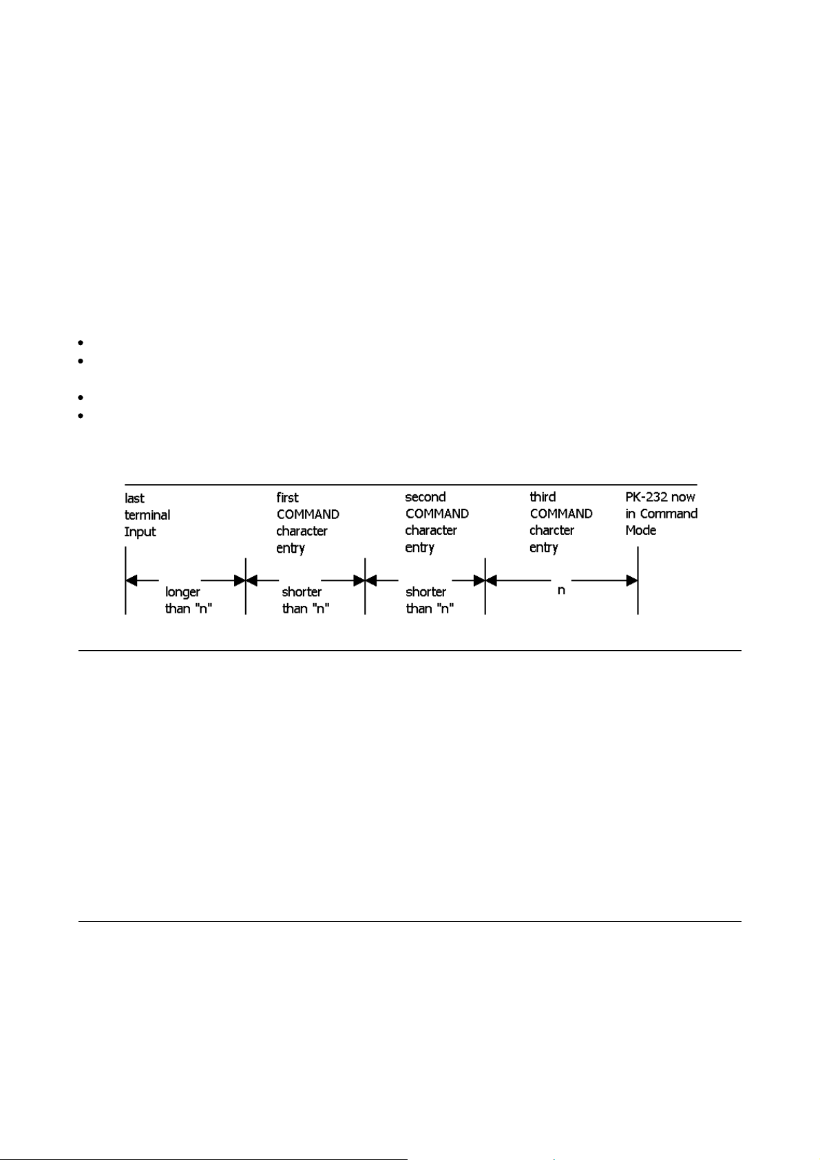
PK-88 OPERATING MANUAL COMMAND SUMMARY
CMDTIME
Parameters:
n
n
0 to 250 specifies timeout value in 100-millisecond intervals while in Trans-
Mnemonic: CM Default: 10
parent Mode.
If n is 0 (zero), exit from Transparent Mode requires sending the BREAK signal or interrupting
power to the PK-88.
CMDTIME sets the timeout value in Transparent Mode. A guard time of n seconds allows escape to
Command Mode from Transparent Mode, while permitting any character to be sent as data.
The same Command Mode entry character (default [^C]) used to exit from the Converse Mode is
used to exit Transparent Mode, although the procedure is different.
The Command Mode entry character is set by COMMAND.
Three Command Mode entry characters must be entered less than n seconds apart, with no intervening characters, after a delay of n seconds following the last characters typed.
After a final delay of n seconds, the PK-88 exits Transparent Mode and enters Command Mode.
You will then see the normal Command Mode prompt:
cmd:
The following diagram illustrates this timing:
CMSG ON|OFF Mnemonic: CMS Default: OFF
Parameters: ON The stored CTEXT message is sent as the first packet after a connection is
established by a connect request from a distant station.
OFF The text message is not sent at all.
CMSG enables or disables automatic transmission of the CTEXT message when your PK-88 accepts
a connect request from another station.
⇒ Set CMSG ON to tell callers that you are not available to answer calls manually when they con-
nect to your PK-88.
⇒ Set CMSG OFF when available to operate or answer calls manually.
COMMAND
Parameters:
n
n
Mnemonic: COM Default: $03 <CTRL-C>
0 to $7F (0 to 127 decimal) specifies an ASCII character code.
COMMAND is used to change the Command Mode entry character. You can enter the code in either
hexadecimal or decimal numbers.
5 - 23 PK-88 - 98
Page 99

PK-88 OPERATING MANUAL COMMAND SUMMARY
Type the COMMAND character to enter Command Mode from Converse Mode. No response is seen
if you type the Command Mode entry character while you are already in Command Mode.
⇒ Enter Converse Mode by typing: CONVERSE
Now, all characters typed on the keyboard and characters send from a disk or tape file are transmitted as packet data.
Type [^C]. The Command Mode prompt appears, indicating successful exit to Command Mode.
The display might look like this:
cmd:
CONVERSE
Hello world! This is a test transmission. [^C]
cmd:
See CMDTIME or the discussion of Transparent Mode for instructions on the Command Mode entry
character to escape from Transparent Mode.
CONMODE CONVERS|TRANS Mnemonic: CONM Default: CONVERS
Parameters: CONVERS The PK-88 automatically enters Converse Mode when a connection is
established.
TRANS The PK-88 automatically enters Transparent Mode when a connection
is established.
CONMODE selects the mode the PK-88 uses after entering the CONNECTED state.
The connection may result either from a connect request received from a distant station, or a connection initiated by a CONNECT command that you've typed.
⇒ Set CONMODE to CONVERS for most packet operations.
⇒ Set CONMODE to TRANS if you are using Transparent Mode for a bulletin board program, so
that the correct mode will be entered when your bulletin board receives a connect request.
⇒ If the PK-88 is already in Converse or Transparent Mode when the connection is completed, the
mode will not be changed.
NOTE: Set CONMODE to TRANS for KISS/TCP/IP operation.
CONNECT call1 [VIA call2(,call3...,call9]] Immediate Command
Parameters: call1 Call sign of the distant station to which you wish to be connected.
call2 Optional call sign(s) of up to eight digipeaters via which you'll be repeated to
reach the distant station.
CONNECT sends a connect request to station 'call1,' directly or via one or more digipeaters. Each
call sign can include an optional SSID or extension n, immediately after the call sign.
The part of the command line shown in brackets below is optional. The double-bracketed text
'call3 .... call9' is also optional and is used only when 'VIA call2' is used, that is, when connecting
through one or more digipeaters. (The brackets and quotationmarks are used in this text only for
clarity - please don't type them!)
VIA call2[, call3 .... call9]
5 - 24 PK-88 - 99
Page 100

PK-88 OPERATING MANUAL COMMAND SUMMARY
Type the digipeater fields in the exact sequence you wish to use to route your packets to destination station 'call1.'
If you type CONNECT while the PK-88 is connected, or trying to connect to or disconnect from a
distant station, your monitor will show:
Link state is: CONNECT in progress
If the distant station does not 'ack' your connect request after the number of tries specified by
RETRY, the CONNECT command is canceled. Your monitor displays:
*** Retry count exceeded
*** DISCONNECTED: (call sign)
To connect directly to WX1AAA, type:
cmd:
CONNECT WX1AAA (or C WX1AAA)
To connect to WX1AAA using WX2BBB (with whom you can easily connect and WX3CCC (who is
near WX1AAA) as digipeaters, type:
cmd:
CONNECT WX1AAA VIA WX2BBB,WX3CCC
Type CONNECT or C without arguments to see the link status and the number of unacknowledged,
outstanding packets.
CONOK ON|OFF Mnemonic: CONO Default: ON
Parameters: ON Functions identically to CFROM ALL.
OFF Functions identically to CFROM NONE.
CONOK ON|OFF is synonymous with CFROM ALL|NONE and is provided for compatibility with terminal programs and other applications requiring this specific command used in older Packet controllers.
CFROM must have been previously set to either ALL or NONE to use this command.
CONPERM ON|OFF Mnemonic: CONP Default: OFF
Parameters: ON The current connection on the current channel is not allowed to enter the
disconnected state.
OFF The current channel can be connected to and disconnected from other sta-
tions.
When ON, CONPERM forces the PK-88 to maintain the current connection, even when frames to
the other station exceed RETRY attempts for an acknowledgment. RESTART and power off/on cycling do not affect this connected state.
CONPERM can be set only when a connection is established or when a connection is in progress
(being established). CONPERM functions on a channel-by-channel basis when multiple connections
are allowed.
5 - 25 PK-88 - 100
 Loading...