

Page 1
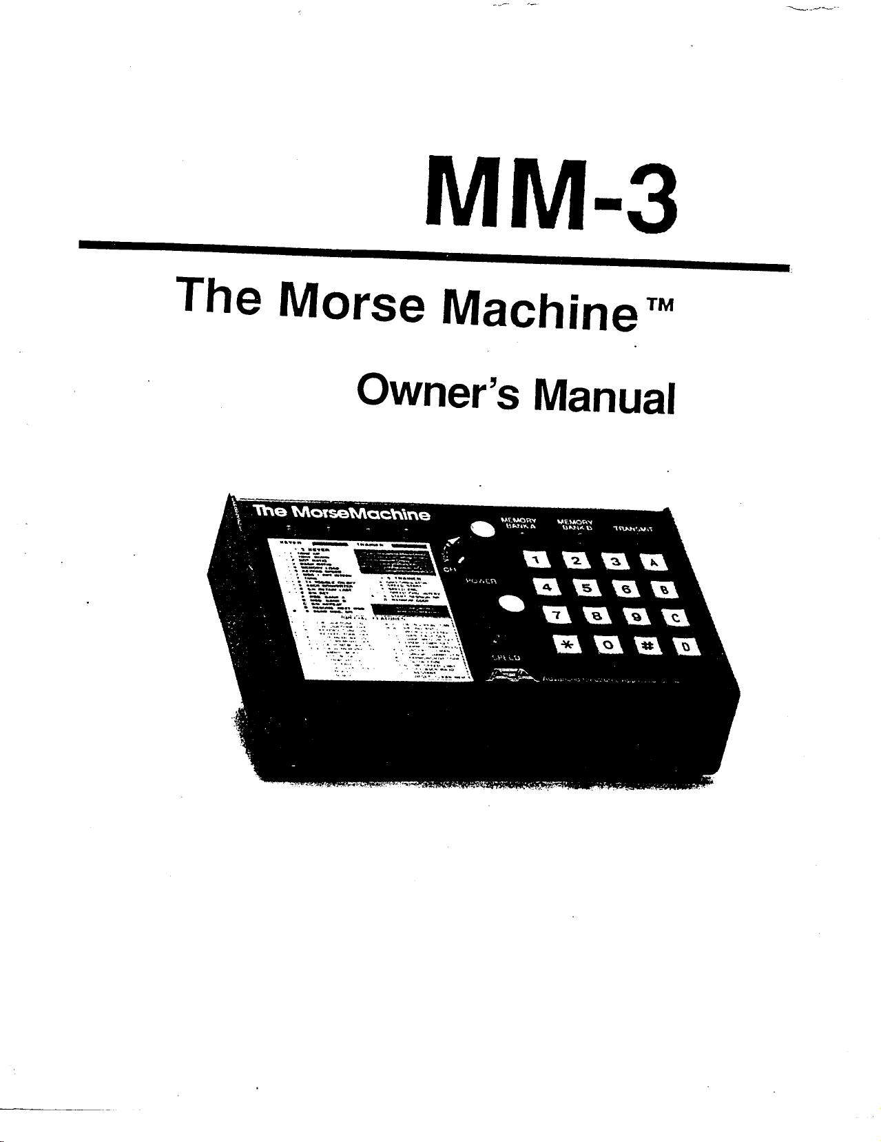
MM-3
The Morse Machine
Owner's Manual
™
Page 2
INTRODUCTION
The Morse Machine is a full-featured, high performance keyer featuring 2-
255 WPM programmable or 2-99 WPM variable speed selection and 8,000
memory characters that can be stored into 20 memories (36,500 characters if
I
32K RAM is used. See page 5). Seven programmable modes of operation are
included: KEYER/MEMORY SEND, BEACON (to automatically repeat a Morse
or RS-232 ASCII message at a programmed interval of one to 999 seconds),
MEMORY LOAD, TRAINER (allows random code group practice at steadily in-
creasing speeds), MORSE TERMINAL, CONTEST SIMULATOR and aso
SIMULATOR.
Whether you're an expert or a novice CW'er, The Morse M~chine will help
improve your code:
A proficiency trainer allows random code group practice with steadily in-
creasing speed
A random word generator generates four-letter words for a more realistic
practice session
A aso simulator simulates asos like those you would hear on the air
A
OX
Contest simulator hones your CW skills
For the serious CW contester, The Morse Machine includes automatic serial
number insertion and incrementing in any memory message. You can use the
front panel knob to adjust your sending speed or enter a precise speed with the
keypad.
A computer serial port can be interfaced to The Morse Machine through its
RS-232 compatible I/O allowing any front panel function to be programmed from
the computer. Loading memories is as simple as typing them on the computer
keyboard. Further, your random code, contest or practice sessions can be dis-
played on your computer screen. •
RF INTERFERENCE
The MM-3 has been certified under SubpartJof Part 15 of the FCC require-
ments. The unit generates and uses radio frequency energy. If the MM-3 is not
installed and used in accordance with this manual, it may cause interference to
radio and TV reception. It has been type-tested and complies with the limits of a
Class 8 computing device in accordance with specifications in SubpartJof Part
15 of the FCC requirements which provides reasonable protection against such
interference in residential installations. If the MM-3 causes interference to radio
or TV reception (test by turning the unit on and off and noting any change in
Page 3
reception), you are encouraged to correct the interference using one or more of
the following measures:
Relocate the computer with respect to the MM-3
Plug the computer into a different outlet than the MM-3
If necessary, you should consult with the dealer or an experienced radiofTV
technician for additional information. You may also find the FCC booklet, "How
to Identify and Resolve Radio-TV Interference Problems" a helpful resource.
Note: Use shielded cable for all connections to your keyer.
LIMITED WARRANTY
ADVANCED ELECTRONIC APPLICATIONS, INC. warrants to the original purchaser
that this product shall be free from defects in material or workmanship for one year from the
date of original purchase. In order to obtain warranty service: 1) Complete and mail the war-
ranty registration card within 10 days to Advanced Electronic Applications, Inc., and 2) Send
written notification to the address below or telephone as soon as possible after discovering a
possible defect:
Advanced Electronic Applications, Inc.
Attention: Service Department
2006-196th St. S.W.
Lynnwood, WA 98036
(206) 775-7373
The written notification must include a copy of the invoice. Include a description of the
defective part or condition, with details of the electrical connections to associated equipment
and list such equipment. Please enclose your name, phone number, and address. Shipping
charges for any parts or units submitted for replacement under this warranty must be paid by
the purchaser.
Correct maintenance, repair and use are important to insure proper performance from
this product. Carefully read the Instruction Manual. This warranty does not apply to any
defect AEA determines is caused by 1) Improper maintenance or repair, including the instal-
lation of parts or accessories that do not conform to the quality and specification of the
original parts; 2) Misuse, abuse, neglect, or improper installation; 3) Accidental or intentional
damage. The field installation of circuits according to the explicit instructions of AEA will not
nullify this warranty.
All implied warranties, if any, terminate one year from the date of original purchase. AEA
is not reponsible for damage to other equipment or property or any other consequential
damages. Some states do not allow limitations of how long an implied warranty lasts or do
not allow the exclusion of incidental or consequential damages, therefore, the above limita-
tions and exclusions may not apply to you.
This warranty gives specific legal rights. You may also have other rights which vary from
state to state.
Page 4
INSTALLATION
POWER
Apply 13 volts DC to the power input jack on the rear panel of the MM-3.
You can easily accomplish this by connecting the cord attached to the optional
AC-1 or AC-4 wall adapters to the power socket on the rear panel of the MM-3.
If you do not have one of the optional power supplies, you must supply 9-16
volts DC to the MM-3 from any external power source Oncluding batteries)
capable of delivering at least 350 mA (see page 5, Low Power). Use the mating
power connector supplied for connecting the MM-3 and the power source. BE
SURE TO OBSERVE PROPER POLARITY. The center pin is positive.
_You can operate the-MM-3-in an automobile by using the optional DC-1
power cord.
PADDLE
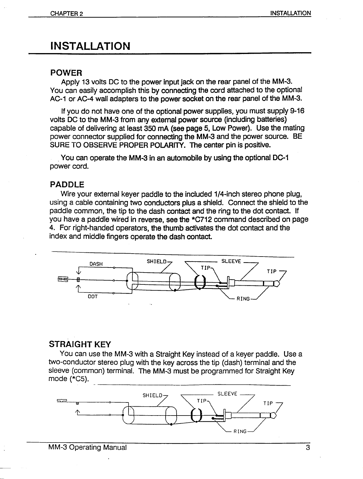
Wire your external keyer paddle to the included 1/4-inch stereo phone plug,
using a cable containing two conductors plus a shield. Connect the shield to the
paddle common, the tip to the dash contact and the ring to the dot contact. If
you have a paddle wired in reverse, see the *C712 command described on page
4. For right-handed operators, the thumb activates the dot contact and the
index and middle fingers operate the dash contact.
STRAIGHT KEY
You can use the MM-3 with a Straight Key instead of a keyer paddle. Use a
two-conductor stereo plug with the key across the tip (dash) terminal and the
sleeve (common) terminal. The MM-3 must be programmed for Straight Key
mode (*C5).
Page 5
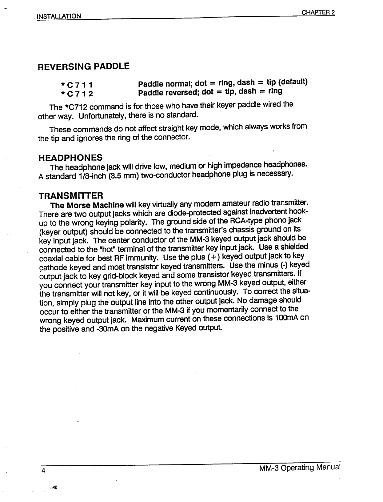
* C 71 1 Paddle normal; dot
* C 7 1 2 Paddle reversed; dot
The *C712 command is for those who havetheir keyer paddle wired the
other way. Unfortunately, there is no standard.
These commands do not affect straight key mode, which always works from
the tip and ignores the ring of the connector.
=
ring, dash
=
tip, dash
=
tip (default)
=
ring
HEADPHONES
The headphone jack will drive low, medium or high impedance headphones.
A standard 1/8-inch (3.5 mm) two-conductor headphone plug is necessary.
TRANSMITTER
The Morse Machine will key virtually any modern amateur radio transmitter.
There are two output jacks which are diode-protected against inadvertent hook-
up to the wrong keying polarity. The ground side of the ReA-type phono jack
(keyer output) should be connected to the transmitter's chassis ground on its
key input jack. The center conductor of the MM-3 keyed output jack should be
connected to the "hot"terminal of the transmitter key input jack. Use a shielded
coaxial cable for best RFimmunity. Use the plus
9athode keyed and most transistor keyed transmitters. Use the minus (-)keyed
output jack to key grid-block keyed and some transistor keyed transmitters. If
you connect your transmitter key input to the wrong MM-3 keyed output, either
the transmitter will not key, or it will be keyed continuously. To correct the situa-
tion, simply plug the output line into the other output jack. No damage should
occur to either the transmitter or the MM-3 ifyou momentarily connect to the
wrong keyed output jack. Maximum current on these connections is 100mAon
the positive and -30mA on the negative Keyed output.
(+)
keyed output jack to key
Page 6
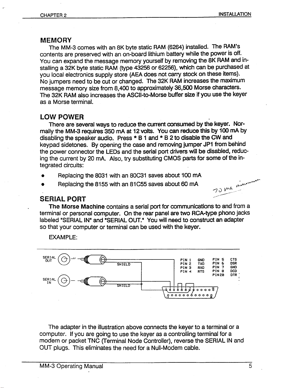
MEMORY
The MM-3 comes with an 8K byte static RAM (6264) installed. The RAM's
contents are preserved with an on-board lithium battery while the power is off.
You can expand the message memory yourself by removing the 8K RAM and in-
stalling a 32K byte static RAM (type 43256 or 62256), which can be purchased at
you local electronics supply store (AEA does not carry stock on these items).
No jumpers need to be cut or changed. The 32K RAM increases the maximum
message memory size from 8,400 to approximately 36,500 Morse characters.
The 32K RAM also increases the ASCII-to-Morse buffer size if you use the keyer
as a Morse terminal.
LOW POWER
There are ·several ways to reduce the current consumed by the keyer. Nor-
mally the MM-3 requires 350 mA at 12 volts. You can reduce this by 100 mA by
disabling the speaker audio. Press * B 1 and * B 2 to disable the CW and
keypad sidetones. By opening the case and removing jumper JP1 from behind
the power connector the LEOs and the serial port drivers will be disabled, reduc-
ing the current by 20 mA. Also, try substituting CMOS parts for some of the in-
tegrated circuits:
• Replacing the 8031 with an 80C31 saves about 100 mA
• Replacing the 8155 with an 81C55 saves about 60 mA
SERIAL PORT
The Morse Machine contains a serial port for communications to and from a
terminal or personal computer. On the rear panel are two RCA-type phono jacks
labeled IISERIAL INIIand HSERIALOUT.II You will need to construct an adapter
so that your computer or terminal can be used with the keyer.
EXAMPLE:
SER I AL
OUT
~-=--
\::::!.)
PIN 1 GNO
PIN Z TXD
PIN 3 RXO
PIN 4 RTS
PIN 5 CTS
PIN G DSR
PIN 7 GND
PIN 8 DCD
PINZB DTR'
I
The adapter in the illustration above connects the keyer to a terminal or a
computer. If you are going to use the keyer as a controlling terminal for a
modem or packet TNC (Terminal Node Controller), reverse the SERIAL IN and
OUT plugs. This eliminates the need for a Null-Modem cable.
Page 7
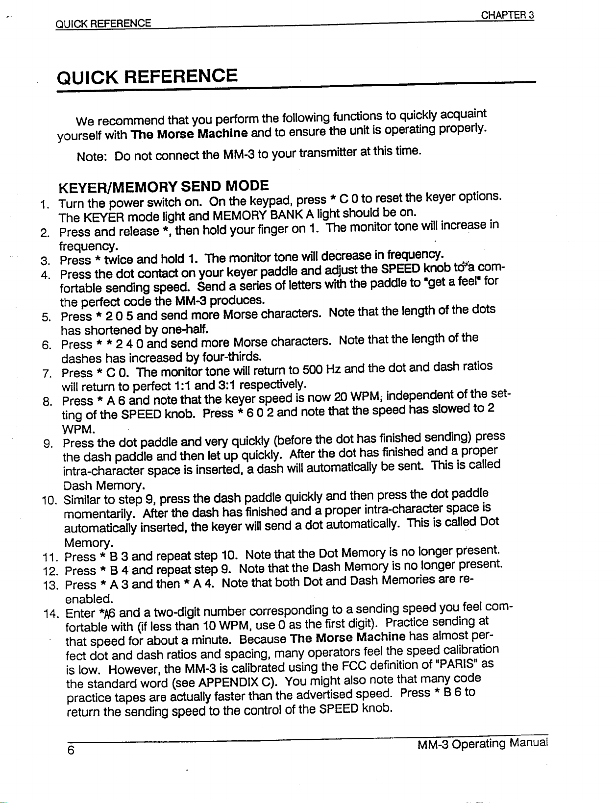
QUICK REFERENCE
We recommend that you perform the following functions to quickly acquaint
yourself with The Morse Machine and to ensure the unit is operating properly.
Note: Do not connect the MM-3 to your transmitter at this time.
KEYER/MEMORY SEND MODE
1. Turn the power switch on. On the keypad, press * C 0 to reset the keyer options.
The KEVER mode light and MEMORY BANK A light should be on.
2. Press and release *, then hold your finger on 1. The monitor tone will increase in
frequency.
3. Press *twice and hold 1. The monitor tone will decrease in frequency.
4. Press the dot contact on your keyer paddle and adjust the SPEED knob td~a com-
fortable sending speed. Send a series of letters with the paddle to "get a feel" for
the perfect code the MM-3 produces.
5. Press * 2 0 5 and send more Morse characters. Note that the length of the dots
has shortened by one-half.
6. Press
dashes has increased by four-thirds.
7. Press *C
will return to perfect 1:1 and 3:1 respectively.
8. Press *A 6 and note that the keyer speed is now 20 WPM; independent of the set-
ting of the SPEED knob. Press * 6 0 2 and note that the speed has slowed to 2
WPM.
9. Press the dot paddle and very quickly (before the dot has finished sending) press
the dash paddle and then let up qUickly. After the dot has finished and a proper
intra-character space is inserted, a dash will automatically be sent. This is called
Dash Memory.
10. Similar to step 9, press the dash paddle quickly and then press the dot paddle
momentarily. After the dash has finished and a proper intra-character space is
automatically inserted, the keyer will send a dot automatically. This is called Dot
Memory. ..
11. Press * B 3 and repeat step 10. Note that the Dot Memory is no longer present.
12. Press * B 4 and repeat step 9. Note that the Dash Memory is no longer present.
13. Press *A 3 and then * A 4. Note that both Dot and Dash Memories are re-
enabled.
14. Enter
fortable with
that speed for about a minute. Because The Morse Machine has almost per-
feet dot and dash ratios and spacing, many operators feel the speed calibration
is low. However, the MM-3 is calibrated using the FCC definition of "PARIS" as
the standard word (see APPENDIX C). You might also note that many code
practice tapes are actually faster than the advertised speed. Press *
return the sending speed to the control of the SPEED knob.
* *
2 4 0 and send more Morse characters. Note that the length of the
O.
The monitor tone will return to 500 Hz and the dot and dash ratios
*A6
and a two-digit number corresponding to a sending speed you feel com-
Of
less than 10 WPM, use 0 as the first digit). Practice sending at
8
6 to
Page 8
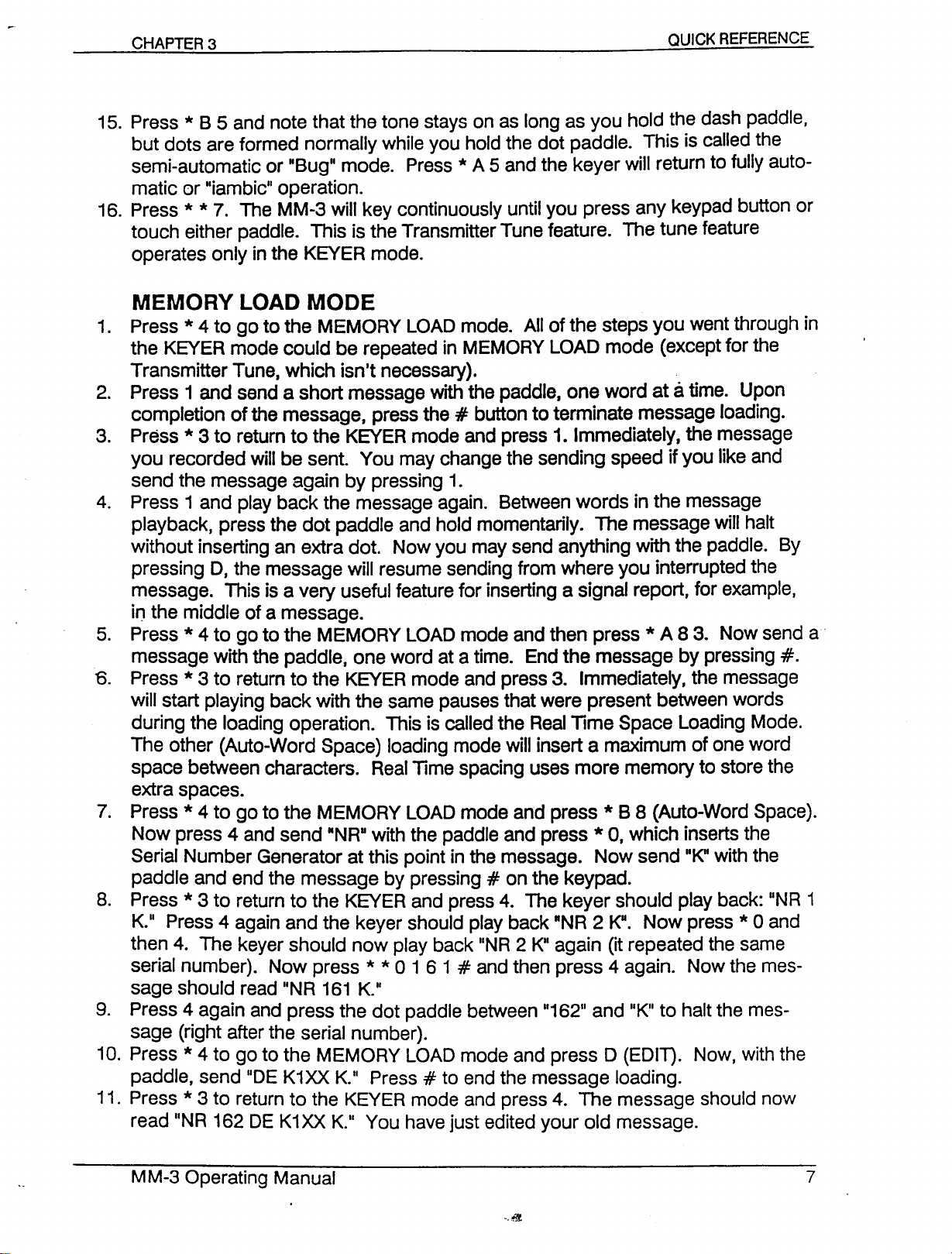
QUICK REFERENCE
15. Press * B 5 and note that the tone stays on as long as you hold the dash paddle,
but dots are formed normally while you hold the dot paddle. This is called the
semi-automatic or "Bug" mode. Press*A 5 and the keyer will return to fully auto-
matic or "iambic" operation.
16. Press
touch either paddle. This is the Transmitter Tune feature. The tune feature
operates only in the KEVER mode.
* *
7. The MM-3 will key continuously until you press any keypad button or
MEMORY LOAD MODE
1. Press *4 to go to the MEMORY LOAD mode. All of the steps you went through in
the KEVER mode could be repeated in MEMORY LOAD mode (except for the
Transmitter Tune, which isn't necessary).
2. Press 1 and send a short message with the paddle, one word atatime. Upon
completion of the message, press the#button to terminate message loading.
3. Press *3 to return to the KEVER mode and press 1. Immediately, the message
you recorded will be sent. You may change the sending speed if you like and
send the message again by pressing 1.
4. Press 1 and play back the message again. Between words in the message
playback, press the dot paddle and hold momentarily. The message will halt
without inserting an extra dot. Now you may send anything with the paddle. By
pressing
message. This is a very useful feature for inserting a signal report, for example,
in the middle of a message.
5. Press * 4 to go to the MEMORY LOAD mode and then press * A 8 3. Now send a .
message with the paddle, one word at a time. End the message by pressing
o.
Press * 3 to return to the KEVER mode and press 3. Immediately, the message
will start playing back with the same pauses that were present between words
during the loading operation. This is called the Real Time Space Loading Mode.
The other (Auto-Word Space) loading mode will insert a maximum of one word
space between characters. Real Time spacing uses more memory to store the
extra spaces.
7. Press *4 to go to the MEMORY LOAD mode and press * B 8 (Auto-Word Space).
Now press 4 and send IlNRUwith the paddle and press*0, which inserts the
Serial Number Generator at this point in the message. Now send 11K"with the
paddle and end the message by pressing#on the keypad.
8. Press *3 to return to the KEVER and press 4. The keyer should play back: "NR 1
K" Press 4 again and the keyer should play back "NR 2 K". Now press *0 and
then 4. The keyer should now play back "NR 2 K" again (it repeated the same
serial number). Now press
sage should read "NR 161 K"
9. Press 4 again and press the dot paddle between "162" and "K" to halt the mes-
sage (right after the serial number).
10. Press*4 to go to the MEMORY LOAD mode and press0(EDIT). Now, with the
paddle, send "DE K1XX K" Press#to end the message loading.
11. Press *3 to return to the KEYER mode and press 4. The message should now
read "NR 162 DE K1XX K" You have just edited your old message.
0,
the message will resume sending from where you interrupted the
* *
0 1 6 1#and then press 4 again. Now the mes-
#.
Page 9
BEACON MODE
1. Press *4 to go to the MEMORY LOAD mode and press 1
message stored in location 1.) Press 1 again and send a message into memory
for about 15 seconds. End the message by pressing
2. Press *8 to go to the BEACON mode. Press * 730
second-hand on your watch comes to the top of a minute. At that precise time,
press 1. The message should play back for 15 seconds at the speed you
loaded in. Note that the BEACON light is blinking on and off. There should be a
15-second pause and then the message will be automatically replayed. A half-
second before the message is replayed, the TRANSMIT light will come on and
after the message ends it will go out.
3. Halt the sequence by pressing the#button on the keypad or by pressing, either
paddle. Increase the sending speed by turning the SPEED knob to tl:1erigUE:.·
Now press 1 and note that the message is sent faster and therefore ends·.~.'-,
sooner, but the silence between messages is longer. If you time the starrar"· "
each transmission you will see that the message still repeats every 30 seconds.
#.
(This erases the old
#.
#.
Now wait until the sweep
TRAINER MODE
1. Press * 5 to go to the TRAINER mode. Press * 6 0 5 and * * 6 20 for a starting
speed of 5 WPM and an ending speed of 20 WPM. Press*7 0 5 0#for8'prac-
tice duration of 5 minutes.
2. Press D and the keyer should start sending code at a 15 WPM character speed
with space between characters such that the beginning word speed is only 5
wpM. The space between characters will shorten gradually until the spacing is
proper for 15 WPM. Then both the character speed and character spacing will
increase in proper proportion until the ending speed of 20 WPM is reached. The
TRAINER will continue to send until you halt it by pressing the#button.
3. Press * C 3 and then D. The Trainer should repeat sending as in step 2 except
that difficult characters will be included. Press#to stop.
4. Press * C 2 and * B 9. Now press D and notice that the difficult characters have
disappeared, but that the Trainer is sending random word lengths and not con-
tinuous five-letter groups. Press#to stop.
5. Press *C 1. Pressing D will now start code practice in four-letter words. Press
to stop.
6. Press * B
gradually speed up to 20 WPM.
7. See Appendix A for the different character sets.
o.
Pressing D will now start slow code. The slow characters will
#
Page 10
ASCII/MORSE CONVERTER MODE
1. Connect a computer's serial port to the keyer. Use the DB-25 (or appropriate con-
nector for your computer) to phono adapter as shown in the Hook- Up Instruc-
tions (page 5).
2. Set up your computer's terminal communications program for 1200 baudIeight
bitsIno parity.
3. Press * 9 to go to the ASCII/MORSECONVERTERmode.
4. On the computer keyboard, type ABC
ters "ABC".
5. On the MM-3 keypad, press * C 3.
6. On the computer keyboard, type ABC + again. This time the keyer should
sound the lettersIIABC" followed by AR. Using the paddle, send some Morse
characters and notice that the computer prints them out on the screen.
7. Set up the terminal program for 300 baudIeight bitsIno parity. On the keyer
keypad, press * C 9 3 and repeat step six to verify that communication stilltakes
place between the keyer and the computer. See chapter 10for more info.
This concludes the quick reference guide of your Morse Machine. If all these
features operate properly, your MM-3 is in good operational condition. If not,
please re-read the instructions and if necessary, start over from the beginning. If
you are still having problems, seeAppendix H regarding technical support.. For
detailed operating instructions, see the appropriate chapter.
+.
The keyer should sound only the let-
Page 11
CONTROL FUNCTIONS
CHAPTER 4
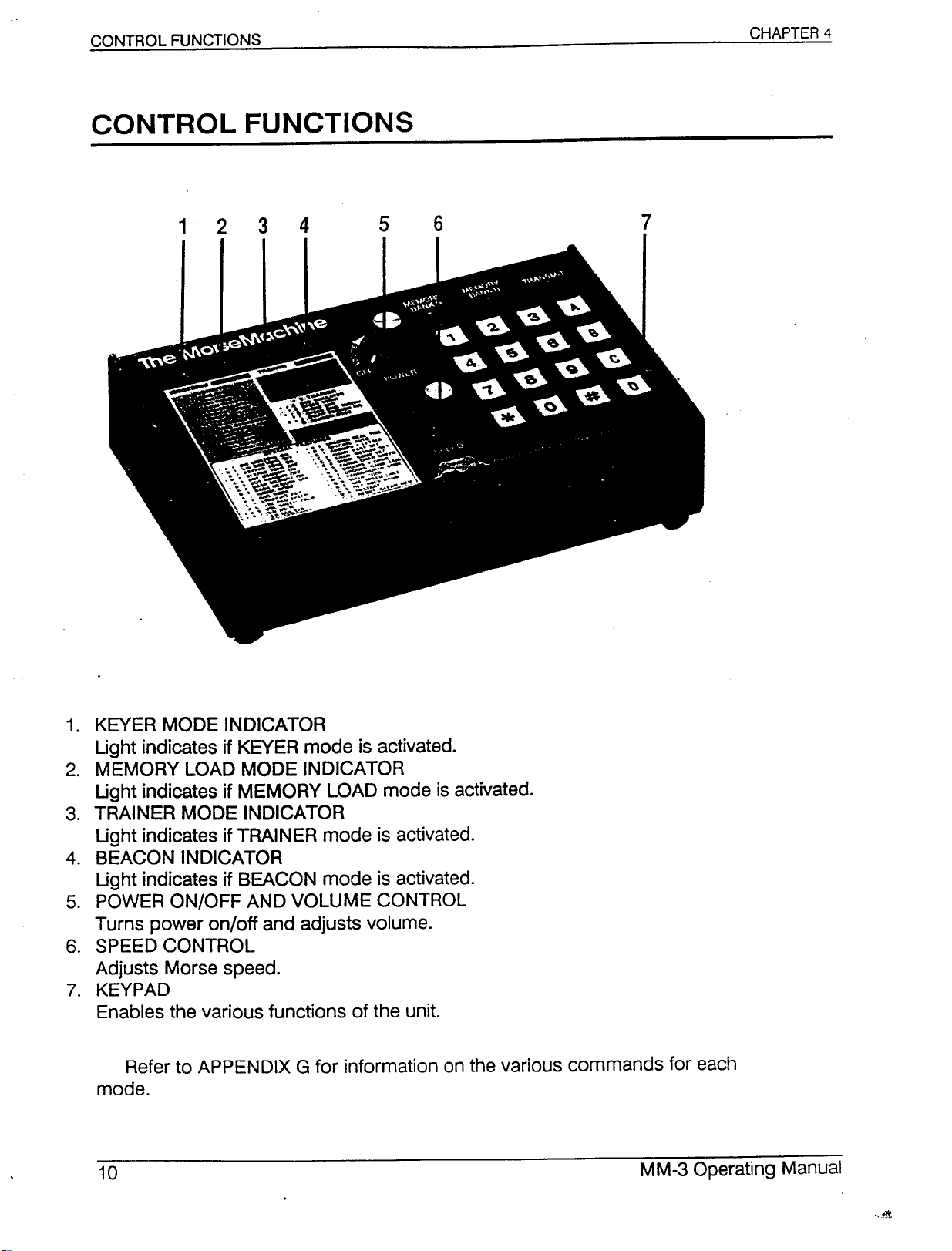
1. KEVER MODE INDICATOR
Ught indicates if KEVER mode is activated.
2. MEMORY LOAD MODE INDICATOR
Light indicates if MEMORY LOAD mode is activated.
3. TRAINER MODE INDICATOR
Light indicates if TRAINER mode is activated.
4. BEACON INDICATOR
Light indicates if BEACON mode is activated.
5. POWER ON/OFF AND VOLUME CONTROL
Turns power on/off and adjusts volume.
6. SPEED CONTROL
Adjusts Morse speed.
7. KEYPAD
Enables the various functions of the unit.
Refer to APPENDIX G for information on the various commands for each
mode.
Page 12
KEYER/MEMORY SEND OPERATION
*A6
*86
*6nn
Keypad controls speed
SPEED knob controls speed
Set sending speed of keypad control
(n=number 0 through 9)
* C 8 6 n n n Set sending speed of keypad control
* C 8 1 n n Set counter-clockwise (lower) SPEED knob limit
* C 8 2 n n Set clockwise (upper) SPEED knob limit
When you first turn on or resetyour MM-3, it is in the KEVERmode. The
SPEEDknob controls the sending speed and the sidetone is set at a tone of 500
Hz. To change the speed, rotate the SPEEDknob.
For exact speeds in words per minute (WPM), press * A 6 to transfer speed
control to the keypad. To change the speed, press *6 and enter the new speed
as two digits, for example1and 5. Ifthe new speed is less than
first digit must be zero. The range of speed is from 2-99 WPM.
Example: To enter 40 WPM, press * 6 4 O.
To enter 7 WPM, press *6 0 7.
Meteor-scatter users may want code faster than 99 WPM. The * C 8 6 com-
mand is similar to the * 6 command, except that three digits of speed are per-
mitted, for a range of 2-255 WPM.
10
WPM, the
To return control of the keyer speed to the SPEED knob, press * 86.
The SPEED knob normally has a range of 5 to 45 WPM, with 5 WPM in the
completely counter-clockwise position and 45 WPM in the completely clockwise
position. To change the SPEEDknob range, use the * C 8 1 and * C 8 2 com-
mands.
Example: To set the SPEED knob range to 7-50 WPM,
press *C 8 1 0 7 and * C 8 2 5 O.
* 1 Tone pitch higher
* *
1 Tone pitch lower
* A 1 CW sidetone on
* 8 1 CW sidetone off
* A 2 Keypad tone on
* 82 Keypad tone off
Page 13
To raise the sidetone pitch, press * and hold the 1 key until the desired tone
is reached. The tone may be lowered by pressing *twice and holding the 1key,
that is, * * 1. The keypad tone will be slightly lower than the CW monitor tone.
AUTOMATIC AND SEMI-AUTOMATIC OPERATION
*A5
*B5
*C5
*C713
* C 7 1 4 Dot/Dash squeeze generates all dots or all dashes
Once the MM-3 is turned on, it is set to Automatic Keyer operation.
You may operate the keyer in the Semi-automatic mode by pressing *"S"-5.-
The keyer now behaves as a "bug." For character recognition inthe MEMORY
LOAD, MORSE TERMINAL and SIMULA.TORmodes, the keyer recognizes only
dashes from the dash paddle, no matter how quickly you tap the paddle. Se
sure to use both the dot and dash paddles in the Semi-automatic mode. To
return to full Automatic mode, press *A 5. When loading memories or using the
Automatic (Iambic) mode
Semi-automatic (Bug) mode
Straight key mode
Dot/Dash squeeze generates alternating dots and dashes
(default)
aso Simulator, you must use the dot paddle to form dots and the dash paddle
to form dashes.
For Straight Key mode, press * C 5. Now dots and dashes are formed only
on the dash paddle, and the dot paddle has no effect. You may connect a
straight key in place of the keyer paddle. In the Straight Key mode, you may
toad message memories in the MEMORY LOAD mode, send ASCII over the
serial port in the MORSETERMINALmode, and converse in the aso
SIMULA.TORmodes.
The *C714 command is for those unaccustomed to the iambic feature of
modern keyers. If both the dot and dash paddles are closed, the keyer
generates a string of all dots or all dashes, depending on which contact was
closed first. Dot and dash memories are disabled.
*2nn
**2nn
"Perfect" Morse code is sent with the time for a dot equal to the time for a
space between dots (a dot/space ratio of 1.0) and the time for a dash equal to
three space times (a dash/space ratio of 3.0).
The dot/space ratio is adjustable from 0.5 to 1.5 in 0.1 increments, and is set
to 1.0 when the MM-3 is turned on. To adjust the dot/space ratio, press * 2 and
enter the dot ratio in tenths.
Set dot ratio
Set dash ratio
Page 14
Example:To set a dot ratio of 0.7, press*207.
To set a dot ratio of 1.3,press*2 1 3.
If the dot/space ratio is more than 1.5 or less than 0.5, the keyer will ignore
the command.
The dash/space ratio is set to 3.0 when the MM-3 is turned on and is adjus-
table from 2.0 to 4.0 in 0.1 increments. To change the dash ratio, enter
and the new dash ratio.
* *
2
Example:To set a dash ratio of 3.5,press
If the dash/space ratio is more than 4.0 or less than 2.0. the keyer will ignore
the command.
The code speed is automatically adjusted for other than ·perfect" dot and
dash ratios and is based on the standard word ·PARIS.·
*
A 3 Dot memory on
*
8 3 Dot memory off
*
A 4 Dash memory on
*
8 4 Dash memory off
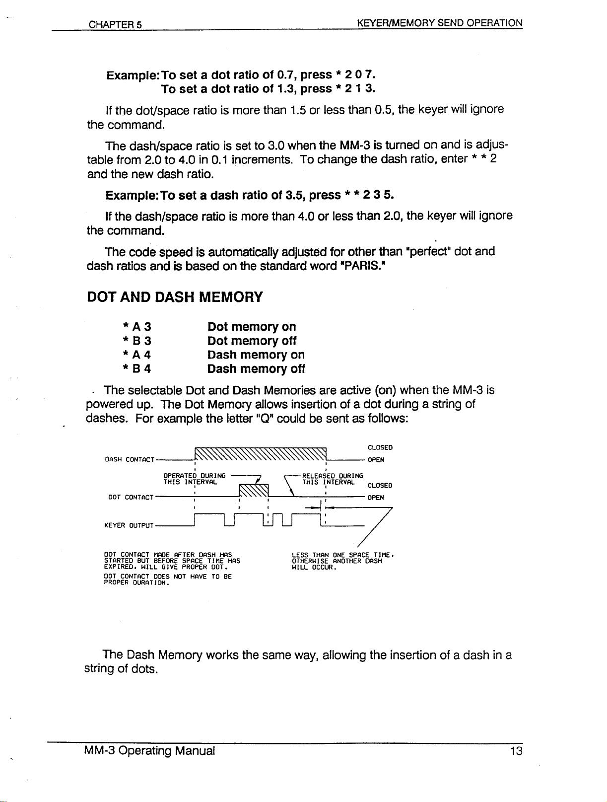
The selectable Dot and Dash Memories are active (on) when the MM-3 is
powered up. The Dot Memory allows insertion of a dot during a string of
dashes. For example the letter
DASH CONTACT
OPERATED DURING -~----
THIS INTERVAL
~ CLOSED
10.."'\.""""",, '\:,,,,,,, '\.",,'\. '\,',,, '\,'\.,,""
I
I
11
110
could be sent as follows:
\RELEASED DURING
THIS ItTERVAL CLOSED
'i~. --
* *
2 3 5.
OPEN
~9
DOT CONTACT MADE AFTER DASH HAS
STARTED BUT BEFORE SPACE TIME HAS
EXPIRED. WILL GIVE PROPER DOT.
DOT CONTACT DOES NOT HAVE TO BE
PROPER DURAT ION.
The Dash Memory works the same way, allowing the insertion of a dash in a
string of dots.
LESS THAN ONE SPACE TIME.
OTHERWISE ANOTHER DASH
WILL OCCUR.
Page 15
To allow transmitter tuning, the keyer output transistors are activated by
pressing * * 7. You can turn off the tuning by pressing any keypad button or
touching either key paddle. The tune feature works only in the KEVER mode.
* C 7 38 CurtistypeA keying
* C739 Curtistype 8 keying
The default is * C 7 3 9 (Curtis B). In type 8 keying, when both paddles"-are
squeezed and released during an element, the iambic feature adds the opposite
element afterwards. In type A keying, the element ends and is not followed by
another.
The transmitter keying outputs are normally enabled in the KEVER mode. To
disable the outputs, press * *
TRANSMIT CONTROL
8
to toggle transmitting off. See also Chapter 11,
#
If you make a mistake programming and the command was not finished, you
can clear it by pressing
rect programming.
#.
If you completed the command, repeat with the cor-
UNACCEPTABLE ENTRIES
The keyer ignores unacceptable entries and sounds an error tone. For ex-
ample, if a speed change is entered * 6 0 1, the result will be no speed change.
*C80nn
There is normally a 20 msec. delay between the activation of the
and the activation of the CW keying outputs. The delay gives linear amplifiers
time to switch to transmit before the output is keyed.IInnllis in units of 10 msec.
The delay can therefore range from 0 to 990 msec (.99 seconds). The default
PIT
output
Page 16
setting is * C 8 0 0 2 (20 msec.). If the PTT output is not used, you should set
the command to * C 8 0 0 0 (no delay).
*
C7 17 Enableautocharacterspacing after 1 dot interval
*
C 7 18 Enableauto characterspacing after 2 dot intervals
*
C 7 19 Disableauto characterspacing from paddle
The space between Morse characters is defined to be 3 dot intervals long. If
auto character spacing is enabled, there is a dead time after the completion of
the last code element until the scheduled beginning of the next character.
During this dead time; the keyer paddle ·is·Adead
begin until exactly 3 silent dot-intervals· have passed. This ensures a full charac-
ter-space between characters. Dot and dash memories are active during the
dead time.
In the * C 71 7 command, the dead time starts after 1 silent dot interval and
has a duration of 2 dot intervals, for tighter control of character spacing. In the *
C 7 1 8 command, the dead time starts after 2 silent dot intervals and lasts for 1
dot interval, for looser control of character spacing.
ll
,
and no dots or-dashes can
The default is * C 7 1 9 (no auto character spacing).
Page 17
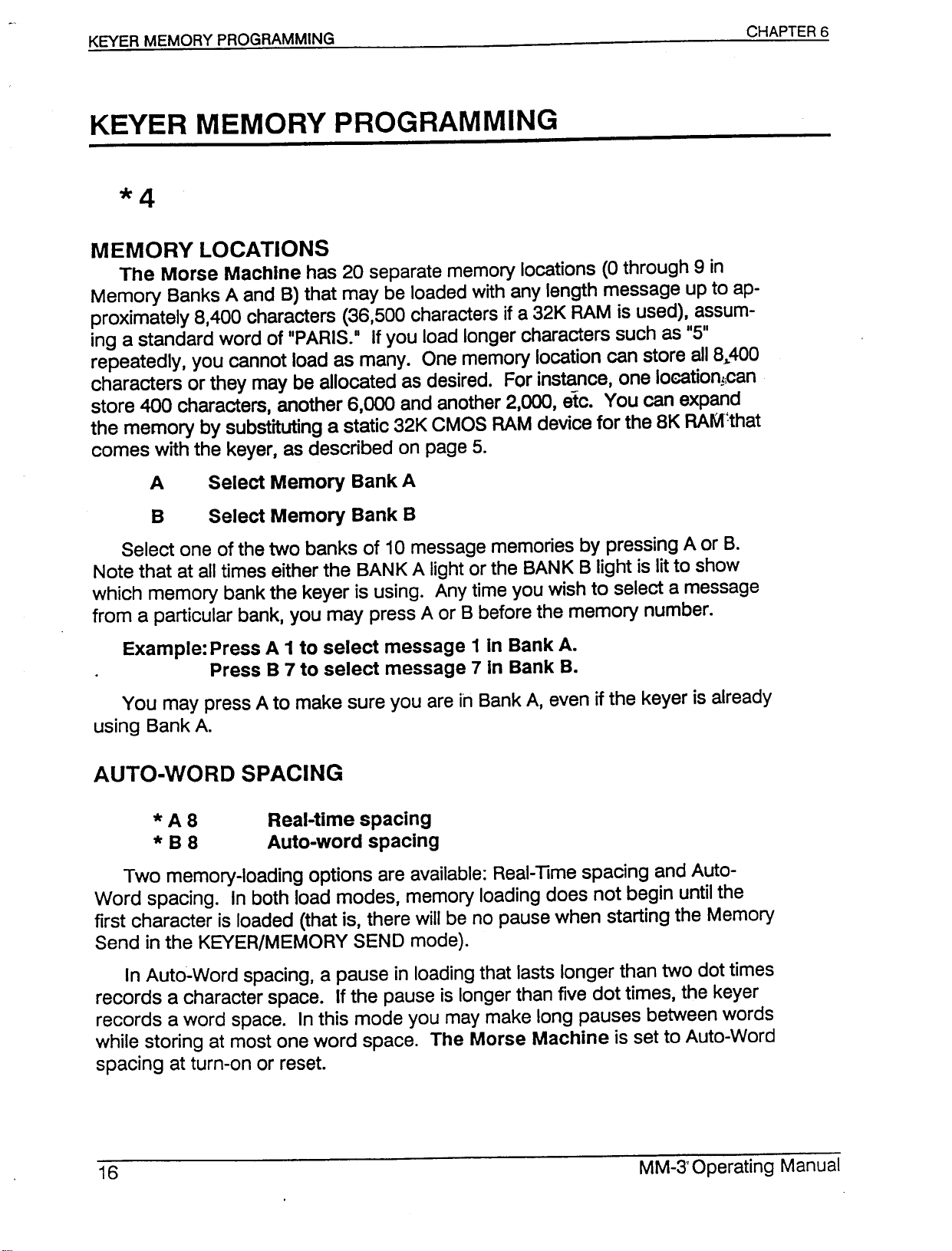
KEVER MEMORY PROGRAMMING
MEMORY LOCATIONS
The Morse Machine has 20 separate memory locations (0 through 9 in
Memory Banks A and B) that may be loaded with any length message up to ap-
proximately 8,400 characters (36,500 characters if a 32K RAM is used), assum-
ing a standard word of "PARIS." If you load longer characters such as "5"
repeatedly, you cannot load as many. One memory location can store a1l8J,.400
characters or they may be allocated as desired. For instance, one loeation;;can
store 400 characters, another 6,000 and another 2,000, etc. You can expand
the memory by substituting a static 32K CMOS RAM device for the 8K RAM:that
comes with the keyer, as described on page 5.
A Select Memory Bank A
B Select Memory Bank B
Select one of the two banks of 10 message memories by pressing A or B.
Note that at all times either the BANK A light or the BANK B light is lit to show
which memory bank the keyer is using. Any time you wish to select a message
from a particular bank, you may press A or B before the memory number.
Example: Press A1to select message 1 In Bank A.
Press B 7 to select message 7 In Bank B.
You may press A to make sure you areinBank A, even if the keyer is already
using Bank A.
*A 8 Real-time spacing
* B 8 Auto-word spacing
Two memory-loading options are available: Real-Time spacing and Auto-
Word spacing. In both load modes, memory loading does not begin until the
first character is loaded (that is, there will be no pause when starting the Memory
Send in the KEVER/MEMORY SEND mode).
In Auto-Word spacing, a pause in loading that lasts longer than two dot times
records a character space. If the pause is longer than five dot times, the keyer
records a word space. In this mode you may make long pauses between words
while storing at most one word space. The Morse Machine is set to Auto-Word
spacing at turn-on or reset.
Page 18
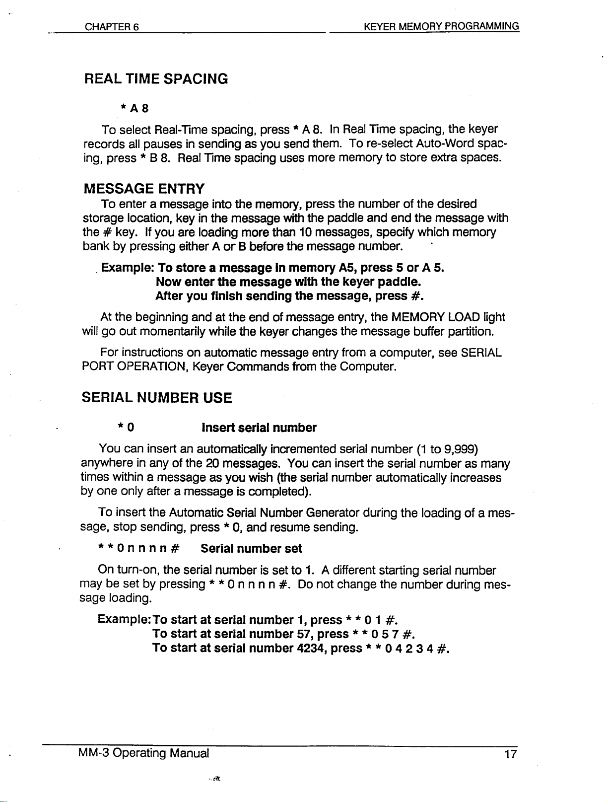
*A8
To select Real-Time spacing, press*A 8. In Real Time spacing, the keyer
records all pauses in sending as you send them. To re-select Auto-Word spac-
ing, press * B 8. Real Time spacing uses more memory to store extra spaces.
MESSAGE ENTRY
To enter a message into the memory, press the number of the desired
storage location, key in the message with the paddle and end the message with
the#key. If you are loading more than 10 messages, specify which memory
bank by pressing either A or Bbefore the message number. .
. Example: To store a message In memory A5, press 5 or A 5.
Now enter the message with the keyer paddle.
After you finish sending the message, press
At the beginning and at the end of message entry, the MEMORY LOAD light
will go out momentarily while the keyer changes the message buffer partition.
For instructions on automatic message entry from a computer, see SERIAL
PORT OPERATION, Keyer Commands from the Computer.
#.
You can insert an automatically incremented serial number (1 to 9,999)
anywhere in any of the 20 messages. You can insert the serial number as many
times within a message as you wish (the serial number automatically increases
by one only after a message is completed).
To insert the Automatic Serial Number Generator during the loading of a mes-
sage, stop sending, press * 0, and resume sending.
* * 0 n n n n
On turn-on, the serial number is set to 1. A different starting serial number
may be set by pressing * * 0 n n n n
sage loading.
Example: To start at serial number 1, press
#
Serial number set
#.
Do not change the number during mes-
* *
To start at serial number 57, press
To start at serial number 4234, press
* *
0 1
057
* *
#.
#.
0 4 2 3 4
#.
Page 19
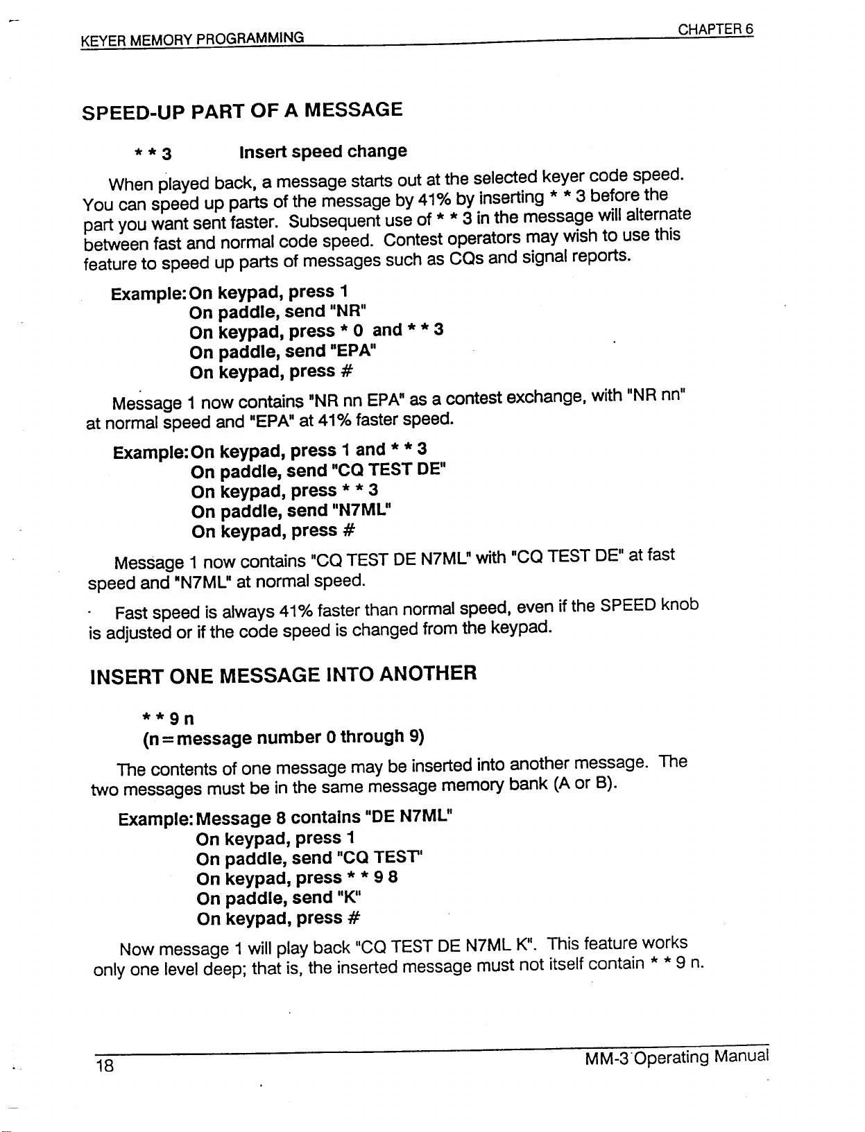
* * 3 Insert speed change
When played back, a message starts out at the selected keyer code speed.
You can speed up parts of the message by 41% by inserting
part you want sent faster. Subsequent use of
between fast and normal code speed. Contest operators may wish to use this
feature to speed up parts of messages such as cas and signal reports.
* *
3 in the message will alternate
* *
3 before the
Example: On keypad, press 1
On paddle, send IINR
II
On keypad, press * 0 and * * 3
On paddle, send nEPA
On keypad, press
Message 1 now contains "NR nn EPA" as a contest exchange, with "NR nn"
at normal speed and "EPA" at 41% faster speed.
II
#
Example: On keypad, press 1 and * * 3
On paddle, send "ca TEST DEli
On keypad, press * * 3
On paddle, send IIN7ML"
On keypad, press
Message 1 now contains IIca TEST DE N7ML" with "Ca TEST DEli at fast
speed and "N7ML" at normal speed.
Fast speed is always 41%faster than normal speed, even if the SPEED knob
is adjusted or if the code speed is changed from the keypad.
#
**9n
(n=message number 0 through 9)
The contents of one message may be inserted into another message. The
two messages must be in the same message memory bank (A or B).
Example: Message 8 contains IIDEN7ML
II
On keypad, press 1
On paddle, send "ca TEST
II
On keypad, press * * 9 8
On paddle, send IIK
On keypad, press
Now message 1 will play back "ca TEST DE N7ML K". This feature works
only one level deep; that is, the inserted message must not itself contain * * 9 n.
II
#
Page 20
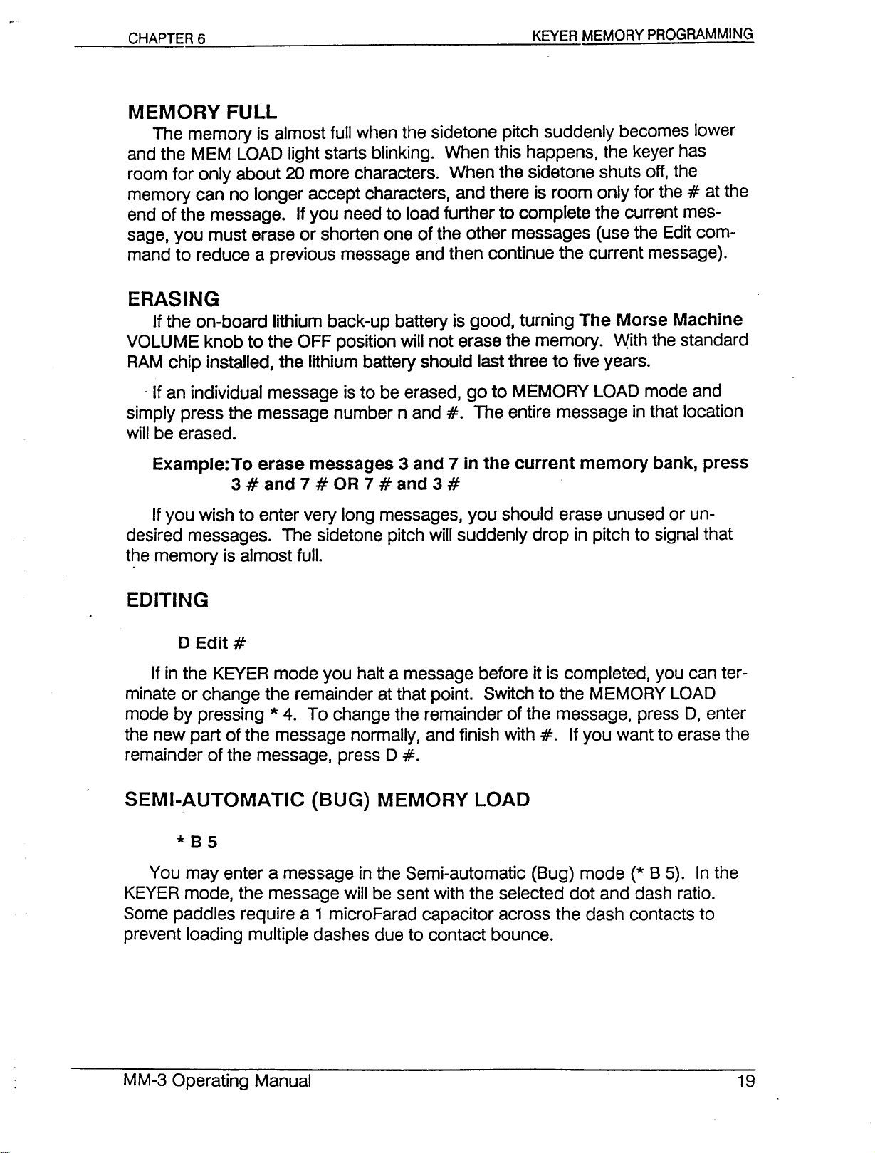
MEMORY FULL
The memory is almost full when the sidetone pitch suddenly becomes lower
and the MEM LOAD light starts blinking. When this happens, the keyer has
room for only about 20 more characters. When the sidetone shuts off, the
memory can no longer accept characters, and there is room only for the#at the
end of the message. If you need to load further to complete the current mes-
sage, you must erase or shorten one of the other messages (use the Edit com-
mand to reduce a previous message and then continue the current message).
ERASING
If the on-board lithium back-up battery is good, turning The Morse Machine
VOLUME knob to the OFF position will not erase the memory. With the standard
RAM chip installed, the lithium battery should last three to five years .
. If an individual message is to be erased, go to MEMORY LOAD mode and
simply press the message number nand
wiil be erased.
Example: To erase messages 3 and 7 in the current memory bank, press
3#and 7#OR 7#and 3
If you wish to enter very long messages, you should erase unused or un-
desired messages. The sidetone pitch will suddenly drop in pitch to signal that
t~e memory is almost full.
#.
The entire message in that location
#
DEdit
If in the KEVER mode you halt a message before it is completed, you can ter-
minate or change the remainder at that point. Switch to the MEMORY LOAD
mode by pressing * 4. To change the remainder of the message, press D, enter
the new part of the message normally, and finish with
remainder of the message, press D
#
#.
If you want to erase the
#.
SEMI-AUTOMATIC (BUG) MEMORY LOAD
*85
You may enter a message in the Semi-automatic (Bug) mode
KEVER mode, the message will be sent with the selected dot and dash ratio.
Some paddles require a 1 microFarad capacitor across the dash contacts to
prevent loading multiple dashes due to contact bounce.
(*
B 5). In the
Page 21
*C5
You may also enter a message in the Straight Key mode (* C 5). In the
KEVER mode, the message will be sent with the selected dot and dash ratio.
Some straight keys require a 1 microFarad capacitor across the contacts to
prevent multiple dot loading due to contact bounce.
The transmitter keying outputs are normally disabled in MEMORY LOAb~~' .
mode .. To enable the outputs, press
* *
8 to toggle transmitting on.
BATTERY LIFE
The internal lithium battery should last three to five years with the standard
CMOS RAM installed. Expanding the memory with to 32 K may reduce the bat-
tery life somewhat.
Page 22
MEMORY SEND OPERATION
*3
The messages stored in any of the 20 memory locations may be sent at any
speed between 2 and 255 WPM, regardless of their loading speed.
Number of message
To start a message, press the number of the desired message. Ifthe light for
Bank A is lit and the message is in Bank B, be sure to press B before the num-
ber.
Example:To send message 61n the current bank, press 6
To send Bank A's message 3, press A 3
REMOTE SENDING
Memory locations1through 4 may be remotely activated. The Remote
Memory jack J5 contains the four message lines plus a common. For fast ac-
cess to messages 1-4 in a contest, you can mount four push-buttons on your
keyer paddle and wire them to J5 as shown below.
REMOTE
MEMORY
#
or key paddle
You may interrupt a message by either pressing the#button or tapping
either of the key paddles. The Morse Machine then enters normal keyer opera-
tion. You may either restart the message by pressing the message number or
resume the message from the point of interruption by pressing D.
Page 23
o
Once a message is finished, pressing D will start the next message in the
series 0-9. Pressing D after message 0 ends will start message 1. Pressing D
after message A 9 ends will start message B 0 without changing the current
memory bank from A to B. Pressing D after message B 9 ends will sound the
error tone.
EDITING
See MEMORY SEND PROGRAMMING, Editing.
SERIAL NUMBER CHANGE OR REPEAT
You"may enter one serial number in a message as many times as you wish.
Serial numbers automatically increase by one only after a message has been
completed.
CHAPTER 7
C Repeat last serial number
It is common in contests for a station to ask for a repeat of the serial number
only. Pressing C causes the keyer to send only the serial number last sent,
without automatically incrementing it.
* * 0 n n n n # Serial number set
In the KEVER mode, you may enter a new serial number. For example: To
reset the serial number to 285, press * * 0 285
not necessary.
If you sent a message with a serial number and the contact was not com-
pleted, press * 0 before making your next contact and the previously sent serial
number will be used again for the new contact.
*7nnn#
Contest operators may wish to have one of the message memories, such as
a CO message, repeat at regular intervals automatically. Message 1 in the cur-
rent memory bank (A or B) can be set up to do this. The range of the Message
1 Repeat Interval is from zero seconds to 999 seconds in one second incre-
ments. The time entry must be terminated with the#key. An interval of zero
seconds disables the repeat feature so that Message 1 is sent only once every
time you press 1. At turn-on or reset, the feature is disabled (interval
#.
Note that leading zeroes are
=
0).
Page 24
Example:To make Message 1 repeat after pausing for 15 seconds,
press *7 1 5
Example:To return Message 1 to normal, non-repeating operation,
press *70#
The BEACON light flashes on and off while the repeat feature is cycling. If
you press the
repeat feature is cycling, Message 1 will not repeat until you press 1 again.
Note: The keyer must be inthe KEVERmode (*3) or Contest Simulator
mode (**4) for the * 7 command to have this effect. The * 7 command has
other functions in other keyer operating modes.
There is a difference in the repeat operation between the KEVERand
BEACON modes. In KEVER,only Message 1 repeats. Pressing any other mes-
sage number key causes Message 1to stop repeating and the new message to
be sent only once. In BEACON,the last memory number pressed is the one that
repeats. The TRANSMIT light and transmitter send-receive output are activated
a half-second before the message repeats.
#,
0-9, C or D buttons or tap either of the key paddles while the
#
and then press 1
*A7
*87
*C721
*C722
*C723
*C724
*C725
*C726
*C727
To save sending time in a contest, some operators prefer to shorten Morse 9
to N and Morse 0 to T. Pressing * B 7 causes the keyer to send the serial num-
ber this way automatically. Press * A 7 to return to literal serial numbers.
These are for customizing the serial number. Many contesters are particular
about this. Note that the commands * A 7 and * B 7 can be implemented with
other commands.
* A 7 does the same thing as * C 7 2 1 and * C 7 2 6
* 8 7 does the same thing as * C 7 2 2 and * C 7 2 7
Serial number as Is
Serial number 9=N, 0=T
o
In a serial number Is sent as a numeral 0 (default)
o
In a serial number Is sent as letter T
o
In a serial number Is sent as letter
1 In a serial number Is sent as numeral 1 (default)
1 In a serial number Is sent as letter A
9 In a serial number Is sent as numeral 9 (default)
9 In a serial number Is sent as letter N
0
Page 25
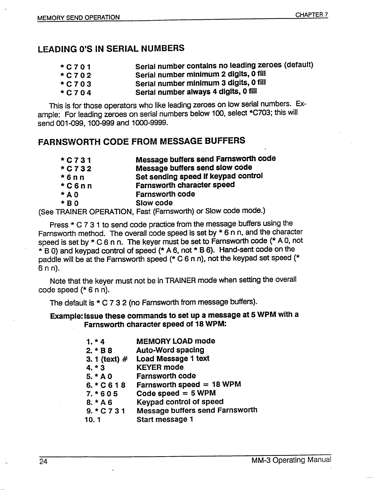
*
C 7 0 1 Serial number contains no leading zeroes (default)
*
C 7 0 2 Serial number minimum 2 digits, 0 fill
*
C 7 0 3 Serial number minimum 3 digits, 0 fill
*
C 7 0 4 Serial number always 4 digits, 0 fill
This is for those operators who like leading zeroes on low serial numbers. Ex-
ample: For leading zeroes on serial numbers below 100. select *C703; this will
send 001-099. 100-999 and 1000-9999.
*
C 7 3 1 Message buffers send Farnsworth code
~C 7 3 2 Message buffers send slow code
*
6 n n Set sending speed if keypad control
*
C 6 n n Farnsworth character speed
*
A 0 Farnsworth code
*
B 0 Slow code
(See TRAINER OPERATION, Fast (Farnsworth) or Slow code mode.)
Press * C 7 3 1 to send code practice from the message buffers using the
Farnsworth method. The overall code speed is set by *6 n n, and the character
speed is set by *C 6 n n. The keyer must be set to Farnsworth code (* A 0, not
* B 0) and keypad control of speed (* A 6. not * B 6). Hand-sent code on the
paddle will be at the Farnsworth speed
6 n n).
(*
C 6 n n), not the keypad set speed
(*
Note that the keyer must not be in TRAINER mode when setting the overall
code speed (* 6 n n).
The default is * C 732 (no Farnsworth from message bUffers).
Example: Issue these commands to set up a message at 5WPM with a
Farnsworth character speed of 18WPM:
1.*4
2.*B 8
3.1 (text)
4.*3
5. * A 0
6.*C 61 8
7.*605
8.*A 6
9.*C 7 31
10. 1
MEMORYLOADmode
Auto-Word spacing
#
Load Message 1text
KEVERmode
Farnsworth code
Farnsworth speed
Code speed
Keypad control of speed
Message buffers send Farnsworth
Start message 1
=
=
5WPM
18WPM
Page 26
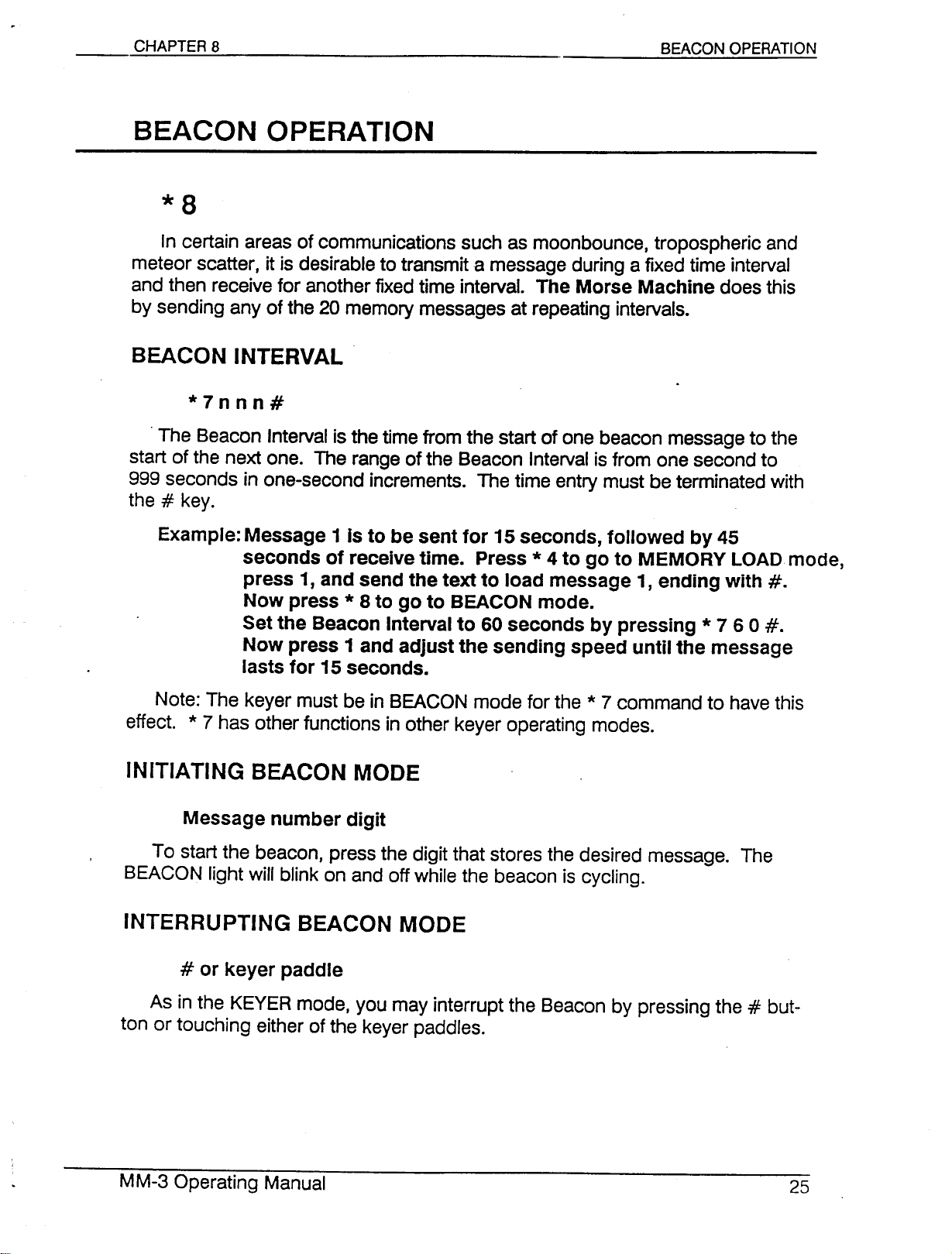
BEACON OPERATION
In certain areas of communications such as moonbounce, tropospheric and
meteor scatter, it is desirable to transmit a message during a fixed time interval
and then receive for another fixed time interval. The Morse Machine does this
by sending any of the 20 memory messages at repeating intervals.
*7nnn#
.The Beacon Interval is the time from the start of one beacon message to the
start of the next one. The range of the Beacon Intervalis from one second to
999 seconds in one-second increments. The time entry must be terminated with
the#key.
Example: Message 1 Is to be sent for 15 seconds, followed by 45
seconds of receive time. Press * 4 to go to MEMORY LOAD mode,
press 1, and send the text to load message 1, ending with #.
Now press * 8 to go to BEACON mode.
Set the Beacon Interval to 60 seconds by pressing * 7 6 0 #.
Now press 1 and adjust the sending speed until the message
lasts for 15 seconds.
Note: The keyer must be in BEACON mode for the * 7 command to have this
effect. * 7 has other functions in other keyer operating modes.
Message number digit
To start the beacon, press the digit that stores the desired message. The
BEACON light will blink on and off while the beacon is cycling.
# or keyer paddle
As in the KEYERmode, you may interrupt the Beacon by pressing the#but-
ton or touching either of the keyer paddles.
Page 27
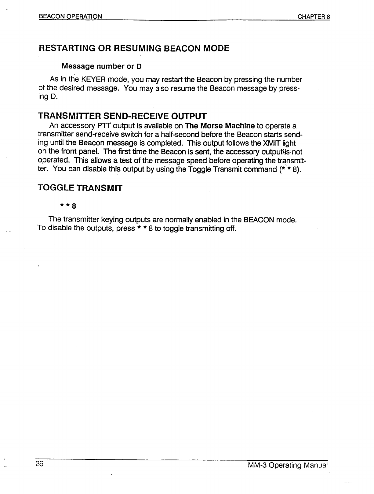
Message number or 0
As in the KEVER mode, you may restart the Beacon by pressing the number
of the desired message. You may also resume the Beacon message by press-
ing
D.
TRANSMITTER SEND-RECEIVE OUTPUT
An accessory PTT output is available on The Morse Machine to operate a
transmitter send-receive switch for a half-second before the Beacon starts send-
ing until the Beacon message is completed. This output follows the XMIT light
on the front panel. The first time the Beacon is sent, the accessory outpuUis~not
operated. This allows a test of the message speed before operating the tr~nsmit-
ter. You can disable this output by using the Toggle Transmit command
The transmitter keying outputs are normally enabled in the BEACON mode.
To disable the outputs, press * * 8 to toggle transmitting off.
(**
8).
Page 28
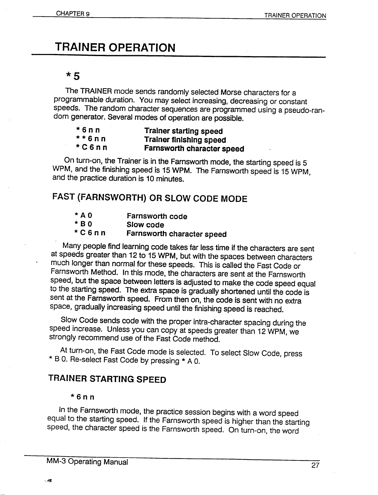
TRAINER OPERATION
TRAINER OPERATION
*5
The TRAINER mode sends randomly selected Morse characters for a
programmable duration. You may select increasing, decreasing or constant
speeds. The random character sequences are programmed using a pseudo-ran-
dom generator. Several modes of operation are possible.
*
6n n Trainerstarting speed
* *
6 n n Trainerfinishing speed
*
C6 n n Farnsworthcharacterspeed
On turn-on, the Trainer is in the Farnsworth mode, the starting speed is 5
WPM, and the finishing speed is 15 WPM. The Farnsworth speed is 15 WPM,
and the practice duration is 10 minutes.
FAST (FARNSWORTH) OR SLOW CODE MODE
*
A 0 Farnsworthcode
*
8 0 Slowcode
*
C6 n n Farnsworthcharacterspeed
Many people find learning code takes far less time if the characters are sent
at speeds greater than 12 to 15 WPM, but with the spaces between characters
much longer than normal for these speeds. This is called the Fast Code or
Farnsworth Method. In this mode, the characters are sent at the Farnsworth
speed, but the space between letters is adjusted to make the code speed equal
to the starting speed. The extra space is gradually shortened until the code is
sent at the Farnsworth speed. From then on, the code is sent with no extra
space, gradually increasing speed until the finishing speed is reached.
Slow Code sends code with the proper intra-character spacing during the
speed increase. Unless you can copy at speeds greater than 12 WPM, we
strongly recommend use of the Fast Code method.
At turn-on, the Fast Code mode is selected. To select Slow Code, press
* B
O.
Re-select Fast Code by pressing * A
O.
*6nn
In the Farnsworth mode, the practice session begins with a word speed
equal to the starting speed. If the Farnsworth speed is higher than the starting
speed, the character speed is the Farnsworth speed. On turn-on, the word
Page 29
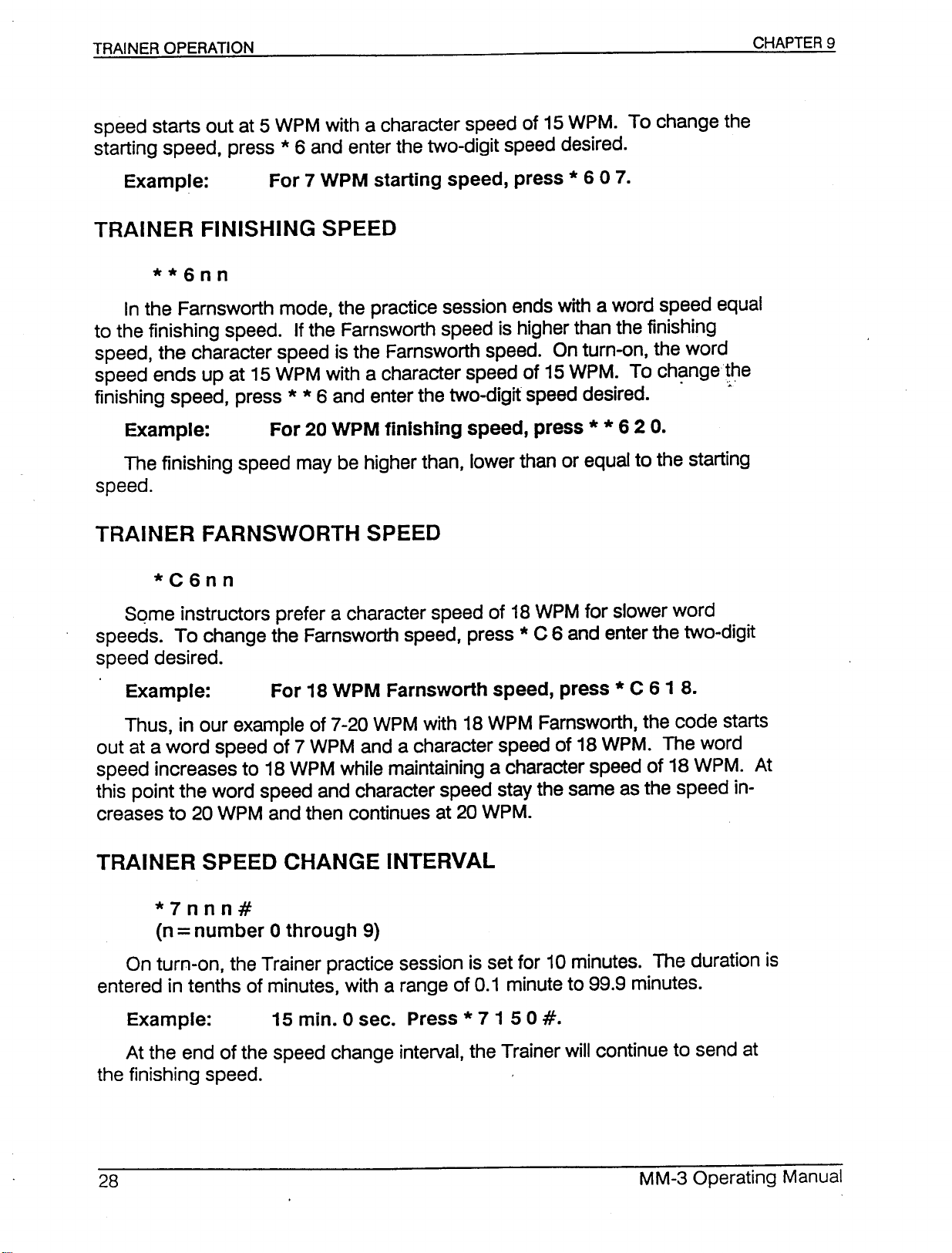
speed starts out at 5 WPM with a character speed of 15WPM. To change the
starting speed, press*6 and enter the two-digit speed desired.
Example: For 7 WPM starting speed, press * 607.
In the Farnsworth mode, the practice session ends with a word speed equal
to the finishing speed. Ifthe Farnsworth speed is higher than the finishing
speed, the character speed is the Farnsworth speed. On turn-on, the word
speed ends up at 15WPM with a character speed of 15WPM. To change the
finishing speed, press
* *
6 and enter the two-digit speed desired. . .~.
Example: For 20 WPM finishing speed, press * * 6 2
The finishing speed may be higher than, lower than or equal to the starting
speed.
*C6nn
Sqme instructors prefer a character speed of 18WPM for slower word
speeds. To change the Farnsworth speed, press*C 6 and enter the two-digit
speed desired.
Example: For 18 WPM Farnsworth speed, press * C 6 1 8.
Thus, in our example of 7-20 WPM with 18WPM Farnsworth, the code starts
out at a word speed of 7 WPM and a character speed of 18 WPM. The word
speed increases to 18 WPM while maintaining a character speed of 18 WPM. At
this point the word speed and character speed stay the same as the speed in-
creases to 20 WPM and then continues at 20 WPM.
O.
*7nnn#
(n=number 0 through 9)
On turn-on, the Trainer practice session is set for 10minutes. The duration is
entered in tenths of minutes, with a range of 0.1 minute to 99.9 minutes.
Example: 15 min. 0 sec. Press * 71 50#.
At the end of the speed change interval, the Trainer will continue to send at
the finishing speed.
Page 30
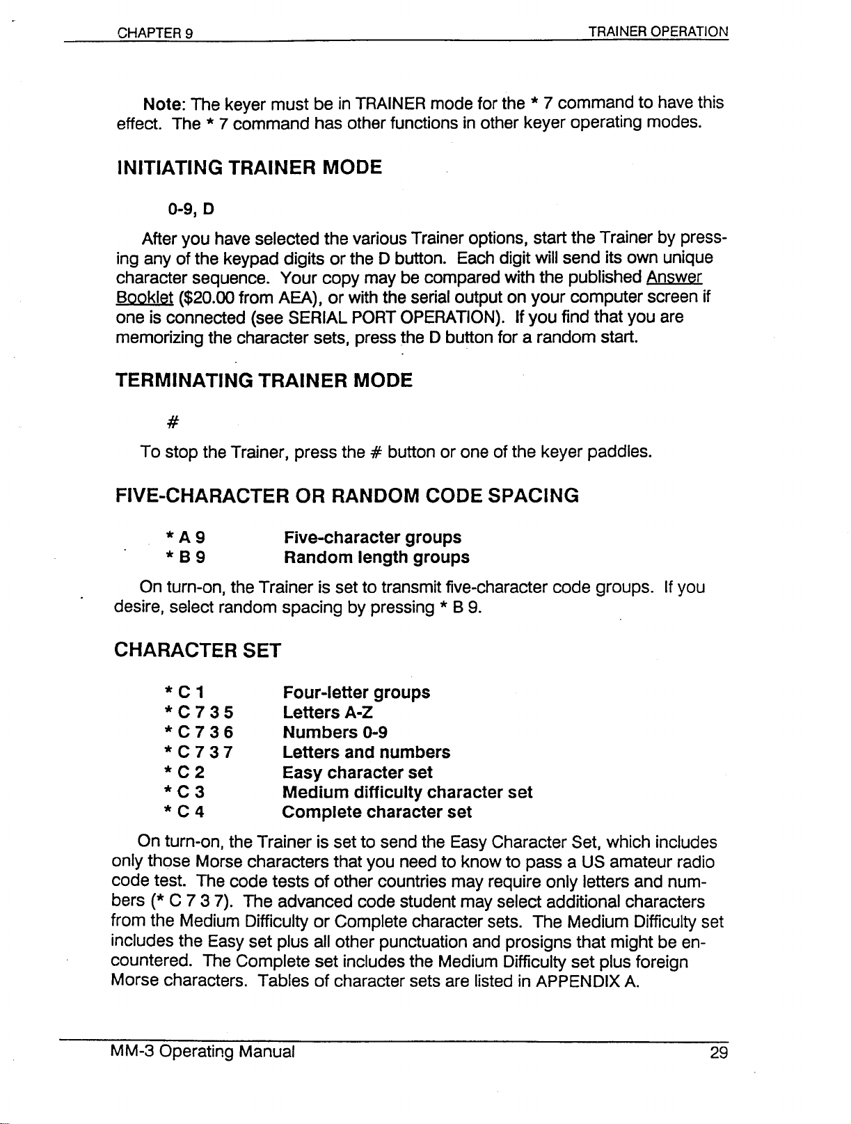
Note: The keyer must be in TRAINERmode for the * 7 command to have this
effect. The * 7 command has other functions in other keyer operating modes.
0-9,0
After you have selected the various Trainer options, start the Trainer by press-
ing any of the keypad digits or the 0 button. Each digit will send its own unique
character sequence. Your copy may be compared with the published Answer
Booklet ($20.00 from AEA), or with the serial output on your computer screen if
one is connected (see SERIAL PORTOPERATION). If you find that you are
memorizing the character sets, press the D button for a random start.
#
To stop the Trainer, press the#button or one of the keyer paddles.
* A 9 Five-character groups
* 8 9 Random length groups
On turn-on, the Trainer is set to transmit five-character code groups. Ifyou
desire, select random spacing by pressing * B 9.
* C 1 Four-letter groups
* C 7 3 5 Letters A-Z
* C 7 3 6 Numbers 0-9
* C 7 3 7 Letters and numbers
* C 2 Easy character set
* C 3 Medium difficulty character set
* C 4 Complete character set
On turn-on, the Trainer is set to send the Easy Character Set, which includes
only those Morse characters that you need to know to pass a US amateur radio
code test. The code tests of other countries may require only letters and num-
bers (* C 737). The advanced code student may select additional characters
from the Medium Difficulty or Complete character sets. The Medium Difficulty set
includes the Easy set plus all other punctuation and prosigns that might be en-
countered. The Complete set includes the Medium Difficulty set plus foreign
Morse characters. Tables of character sets are listed in APPENDIX A.
Page 31
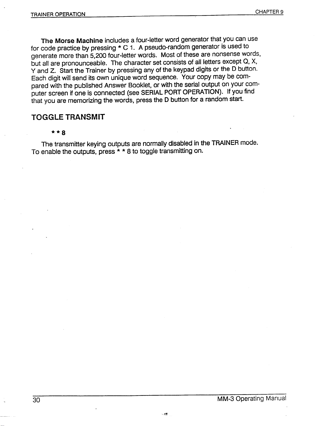
The Morse Machine includes a four-letter word generator that you can use
for code practice by pressing * C 1. A pseudo-random generator is used to
generate more than 5,200 four-letter words. Most of these are nonsense words,
but all are pronounceable. The character set consists of all letters except
Q,
X,
Y and Z. Start the Trainer by pressing any of the keypad digits or the0button.
Each digit will send its own unique word sequence. Your copy may be com-
pared with the pUblished Answer Booklet, or with the serial output on your com-
puter screen if one is connected (see SERIAL PORT OPERATION). If you find
that you are memorizing the words, press the0button for a random start.
The transmitter keying outputs are normally disabled in the TRAINER mode.
To enable the outputs, press * * 8 to toggle transmitting on.
Page 32
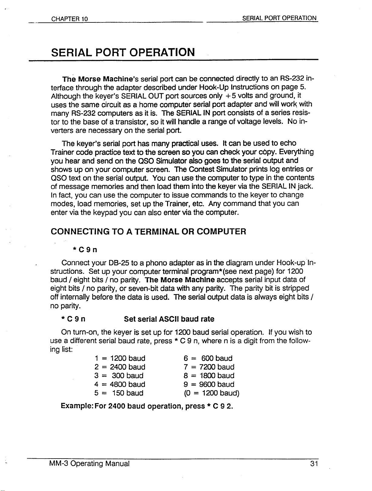
SERIAL PORT OPERATION
The Morse Machine's serial port can be connected directly to an RS-232in-
terface through the adapter described under Hook-Up Instructions on page 5.
Although the keyer's SERIALOUT port sources only +5 volts and ground, it
uses the same circuit as a home computer serial port adapter and will work with
many RS-232computers as it is. The SERIALIN port consists of a series resis-
tor to the base of a transistor, so it will handle a range of voltage levels. No in-
verters are necessary on the serial port.
The keyer's serial port has many practical uses. It can be used to echo
Trainer code practice text to the screen so you can check your cOpy.Everything
you hear and send on the aso Simulator also goes to the serial output and
shows up on your computer screen. The Contest Simulator prints log entries or
aso text on the serial output. You can use the computer to type in the contents
of message memories and then load them into the keyer via the SERIALINjack.
Infact, you can use the computer to issue commands to the keyer to change
modes, load memories, set up the Trainer, etc. Any command that you can
enter via the keypad you can also enter via the computer.
*C9n
Connect your 08-25 to a phono adapter as in the diagram under Hook-up In-
structions. Set up your computer terminal program*(see next page) for 1200
baud / eight bits / no parity. The Morse Machine accepts serial input data of
eight bits / no parity, or seven-bit data with any parity. The parity bit is stripped
off internally before the data is used. The serial output data is always eight bits /
no parity.
* C 9 n Set serial ASCII baud rate
On turn-on, the keyer is set up for 1200 baud serial operation. Ifyou wish to
use a different serial baud rate, press * C 9 n, where n is a digit from the follow-
ing list:
1=1200 baud 6
2=2400 baud 7=7200 baud
3
=
300 baud 8=1800baud
4=4800 baud 9=9600 baud
5
=
150 baud (0=1200baud)
Example: For 2400 baud operation, press * C 9 2.
=
600 baud
Page 33
CONNECTING TO A MODEM OR PACKET TNC
(TERMINAL NODE CONTROLLER)
Connect the adapter as in the diagram under Hook-Up Instructions (page 5).
except reverse the RCA-type phono plugs on the SERIAL IN and SERIAL OUT
jacks. This will eliminate the need for a Null-Modem adapter cable.
MORSE-TO-ASCII DATA TO THE COMPUTER
In all modes except MEMORY LOAD, the Morse code from the paddle is
translated to ASCII and sent to the SERIAL OUT line.
KEVER COMMANDS FROM THE COMPUTER
In all operating modes except ASCII/MORSE CONVERTER, the ASCII t~pt
the computer sends to the keyer is interpreted as a command stream that 'con-
trois the keyer the same way the keypad does. You can use this feature to
change keyer operating modes, load message buffers, set various parameters
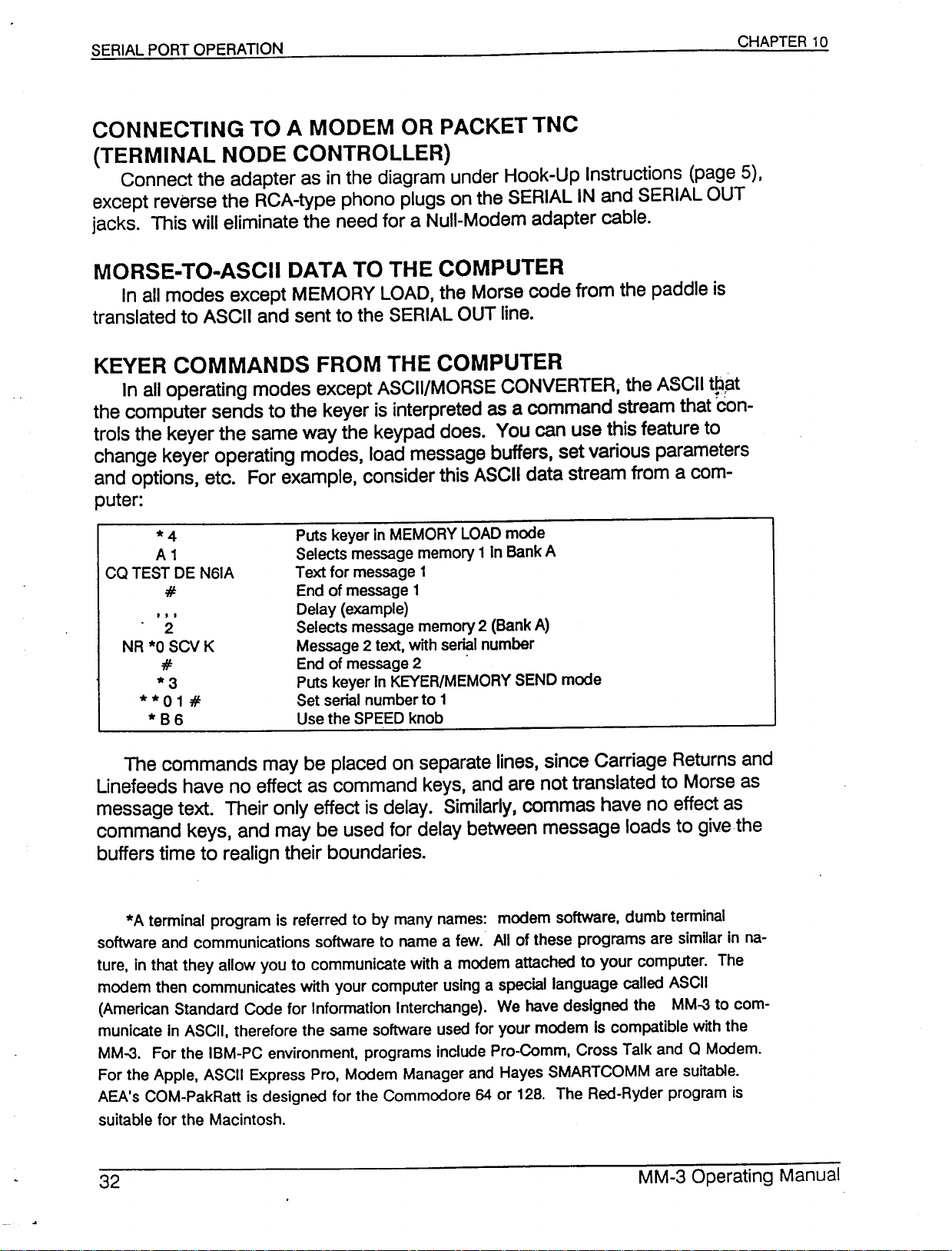
and options, etc. For example, consider this ASCII data stream from a com-
puter:
*4
A1
CO TEST DE N61A
#
. 2
NR*0SCVK
#
*3
**01
#
*B6
Puts keyer in MEMORY LOAD mode
Selects message memory1In Bank A
Text for message
End of message
Delay (example)
Selects message memory 2 (Bank A)
Message 2 text, with serial number
End of message 2 .
Puts keyer In KEVER/MEMORY SEND mode
Set serial number to
Use the SPEED knob
1
1
1
The commands may be placed on separate lines, since Carriage Returns and
Unefeeds have no effect as command keys, and are not translated to Morse as
message text. Their only effect is delay. Similarly, commas have no effect as
command keys, and may be used for delay between message loads to give.the
buffers time to realign their boundaries.
*A terminal program is referred to by many names: modem software, dumb terminal
software and communications software to name a few. All of these programs are similar in na-
ture, in that they allow you to communicate with a modem attached to your computer. The
modem then communicates with your computer using a special language called ASCII
(American Standard Code for Information Interchange). We have designed the MM-3 to com-
municate In ASCII, therefore the same software used for your modem is compatible with the
MM-3. For the IBM-PC environment, programs include Pro-Comm, Cross Talk and 0 Modem.
For the Apple, ASCII Express Pro, Modem Manager and Hayes SMARTCOMM are suitable.
AEA's COM-PakRatt is designed for the Commodore 64 or
suitable for the Macintosh.
128.
The Red-Ryder program is
Page 34
ASCII/MORSE
*9
In most of the keyer operating modes, sending Morse code on the paddle
produces ASCII output to a computer, and ASCII input characters from a com-
puter are treated as commands to the keyer. In the ASCII/MORSE CONVERTER
mode, Morse code sent on a paddle, bug or Straight Key is still converted to
ASCII on the SERIAL OUT line as before, but ASCII on the SERIAL IN line is con-
verted to audible Morse code. This mode turns the keyer into an inexpensive ter-
minal that can be used as a data entry device for a computer, or a master
terminal for a radio communications data controller or telephone· modem.
The Morse paddle speed is controlled by either the SPEED knob or the
keypad, depending on whether * A 6 or * B 6 was pressed. The speed of the in-
coming ASCII-to-Morse is also controlled by either the SPEED knob or the
keypad, depending on whether * C 71 5 or * C 71 6 was pressed. This way
you may send and receive at different speeds if you wish.
USING THE KEVER AS AN I/O DEVICE
When keying in data to be sent to a computer, you can send a carriage
return/linefeed code by sending ..-- on the paddle.
*9
To converse with a TNC or modem, press *9 to set up the converter
BEFORE turning on the TNC. Set * 6 n n to a comfortable receiving speed.
Some TNCs use auto-baud routines to initialize their serial ports. AEA units
such as the PK-232 and PK-88 operate in this manner. With the keyer character
set at any level below Complete (use * C 1, * C 2 or * C 3), send several ---
characters (CH, or four dashes). The keyer translates each of these characters
to an asterisk (*) for the auto-baud routine. Then send the .-.- character, which
is the carriage return. You should then hear the TNC's sign-on message. The
first command to give the TNC is "ECHO OFF.
DO NOT use the ..-- character (CRLF) to end a line; always use the .-.- (CR)
character. The extra Iinefeed confuses the TNC.
II
Page 35
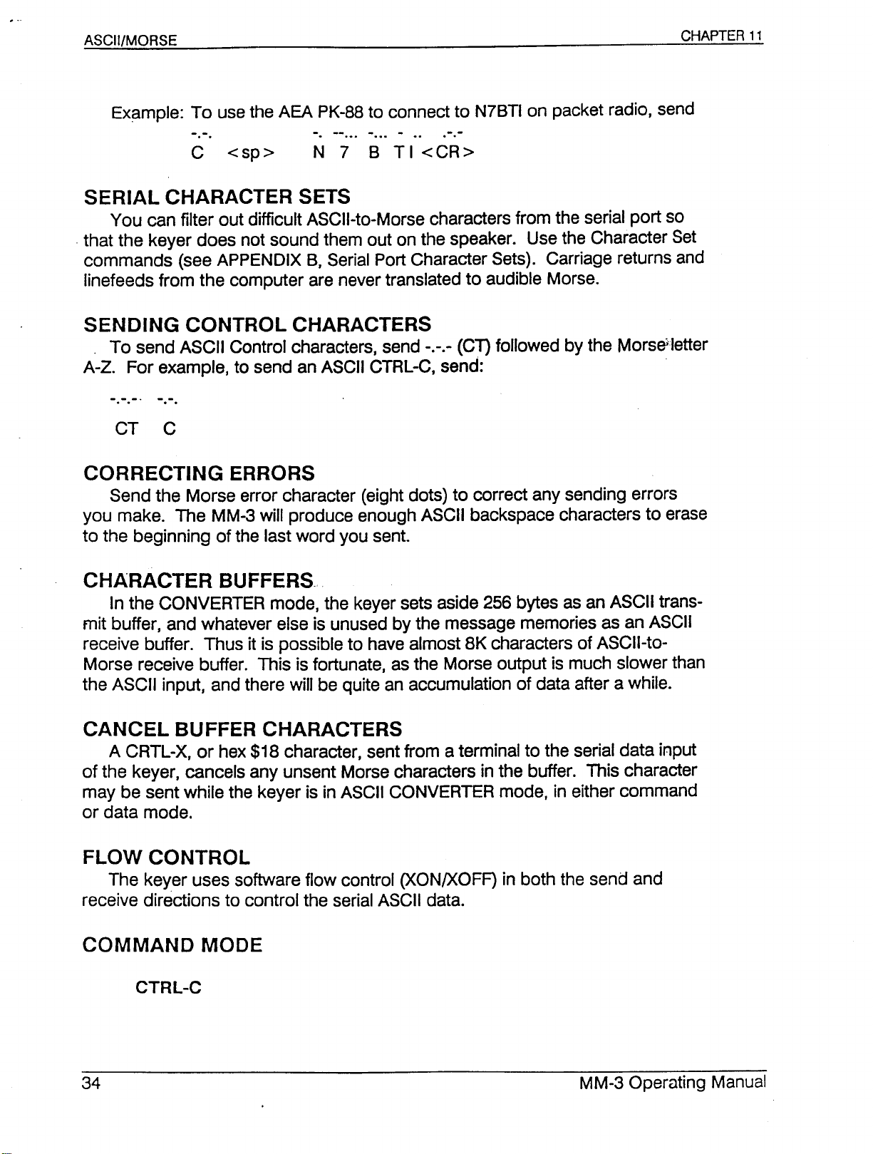
Example: To use the AEA PK-88 to connect to N7BTI on packet radio, send
SERIAL CHARACTER SETS
You can filter out difficult ASCII-to-Morse characters from the serial port so
.that the keyer does not sound them out on the speaker. Use the Character Set
commands (see APPENDIX B, Serial Port Character Sets). Carriage returns and
Iinefeeds from the computer are never translated to audible Morse.
SENDING CONTROL CHARACTERS
To send ASCII Control characters, send -.-.- (Cn followed by the Morseiletter
A-Z. For example, to send an ASCII CTRL-C, send:
CORRECTING ERRORS
Send the Morse error character (eight dots) to correct any sending errors
you make. The MM-3 will produce enough ASCII backspace characters to erase
to the beginning of the last word you sent.
CHARACTER BUFFERS.
In the CONVERTER mode, the keyer sets aside 256 bytes as an ASCII trans-
mit buffer, and whatever else is unused by the message memories as an ASCII
receive buffer. Thus it is possible to have almost 8K characters of ASCII-to-
Morse receive buffer. This is fortunate, as the Morse output is much slower than
the ASCII input, and there will be quite an accumulation of data after a while.
CANCEL BUFFER CHARACTERS
A CRTL-X, or hex $18 character, sent from a terminal to the serial data input
of the keyer, cancels any unsent Morse characters in the buffer. This character
may be sent while the keyer is in ASCII CONVERTER mode, in either command
or data mode.
FLOW CONTROL
The keyer uses software flow control (XON/XOFF) in both the send and
receive directions to control the serial ASCII data.
Page 36
In the ASCII/MORSE CONVERTER mode, the keyer normally treats incoming
ASCII as text to be translated into audible Morse code. However, typing a CTRL-
C from the computer keyboard will place the keyer into the sameIIcommand
ll
mode
TION, Keyer Commands from the Computer, page 27). To return the ASCII
stream to I'data mode,
buffers; the * 9 command does clear the buffers as it re-initializes ASCII/Morse
Converter mode. .
.
as in all the other keyer operating modes (see SERIAL PORT OPERA-
II
type * C 7 0 9. This command does not clear the ASCII
* *
8 Togglethe enablefor PIT and output keying
*
C7 0 5 EnablePIT andkeyingfor current mode
*
C7 0 6 DisablePIT andkeyingfor current mode
*
C7 0 7 Turn on PIT
*
C7 0 8 Turn off PIT
CTRL-D (In CONVERTERdatamode)Turn off PIT
Push-to-Talk and output keying are normally enabled in the ASCII CON-
VERTER mode. To change to the opposite enable state, use the
mand. If the enable state is not known, use the * C 7 0 5 or * C 7 0 6
commands.
* *
8 com-
. The user may turn on PIT from the serial port before starting to transmit
Morse characters. The * C 7 0 7 command turns on PIT, which is then turned
off automatically after 20 seconds of no activity. This type of PIT assertion stays
activated between Morse characters.
If the last character the terminal sends to the keyer is a CTRL-D, the keyer
sends Morse until it gets to the CTRL-D, when it turns off the PIT that the
*
C 707 command activated. After processing the CTRL-D, the keyer is still in
data mode.
Instead of CTRL-D, the terminal may send
CTRL-C
to turn off PIT at the end of a string of data. PIT stays on until all data char-
acters before the CTRL-C are transmitted.
*
C7 15 Keypadcontrols speed of datafrom serial
*
C7 1 6 SPEEDknob controlsspeed of datafrom serial
The ASCII/MORSE CONVERTER mode converts serial data to audible Morse
characters. Either the keypad or the SPEED knob can control the speed of the
Morse characters.
*
C7 0 8
Page 37
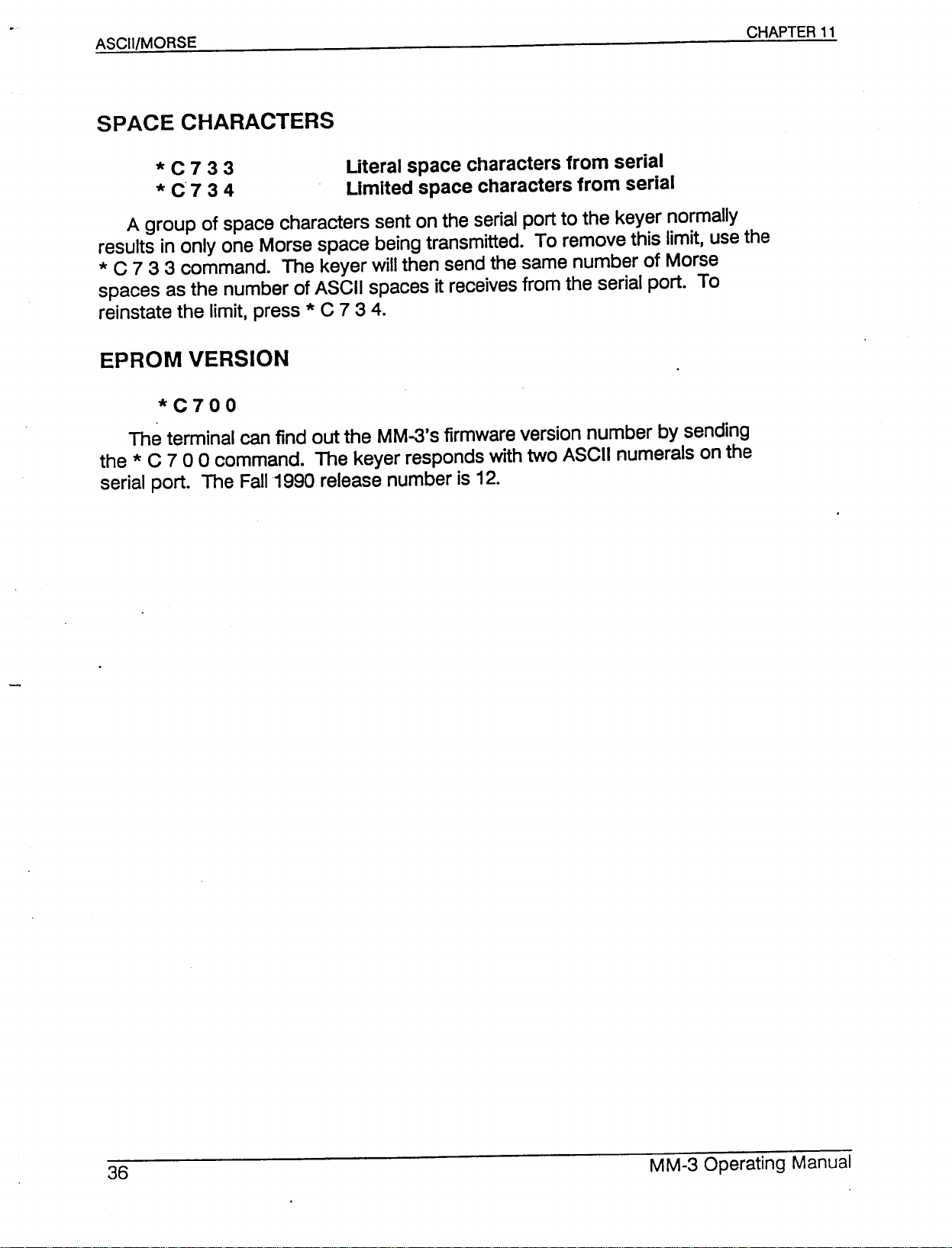
*
C 7 3 3 Literal space charactersfrom serial
*
C'7 3 4 Limited space charactersfrom serial
A group of space characters sent on the serial port to the keyer normally
results in only one Morse space being transmitted. To remove this limit, use the
* C 7 3 3 command. The keyer will then send the same number of Morse
spaces as the number of ASCII spaces it receives from the serial port. To
reinstate the limit, press *C 7 3 4.
*C700
The terminal can find out the MM-3's firmware version number by sending
the *C 7 0 0 command. The keyer responds with two ASCII numerals on the
serial port. The Fall 1990 release number is 12.
Page 38
QSO SIMULATOR
aso SIMULATOR
**5
The OSO Simulator is a Morse code training mode that lets you take part in
everyday amateur radio conversations without actually being on the air. You
need no antenna, no linear amplifier, no postage for OSL cards. You can learn
CW operating skills at your own comfort level.
The OSO Simulator creates computer generated CW signals that call CO, talk
to each other, or talk to you. The keyer simulates the CW portion of an un-
specified amateur band, at no particular time of day, season, or location. Good
radio propagation across the United States is assumed. All call letters of the sta-
tions you hear are random United States call signs.
The typical conversation, or Uragchew", involves exchanging call letters, sig-
nal reports, station locations, .operator names, transmitter types, antennas, and
weather. If you miss a piece of information, you can ask for it to be repeated. If
you make a mistake, the other station may ask you to repeat the information.
You may even ask the other station to slow down (ORS) or speed up (ORO) and
he/she will.
The Morse Machine OSO Simulator is an excellent training aid for prospec-
tive hams, new operators and hams improving their CW speed. It enables you
to send and receive before getting on the air. You can keep track of your
progress by connecting the keyer's serial port to a computer and watching the
text come out on the screen.
Important: End all your transmissions with either K,<KN
QSO Simulator will answer after you send one of these and wait.
>,or<
AR
>.
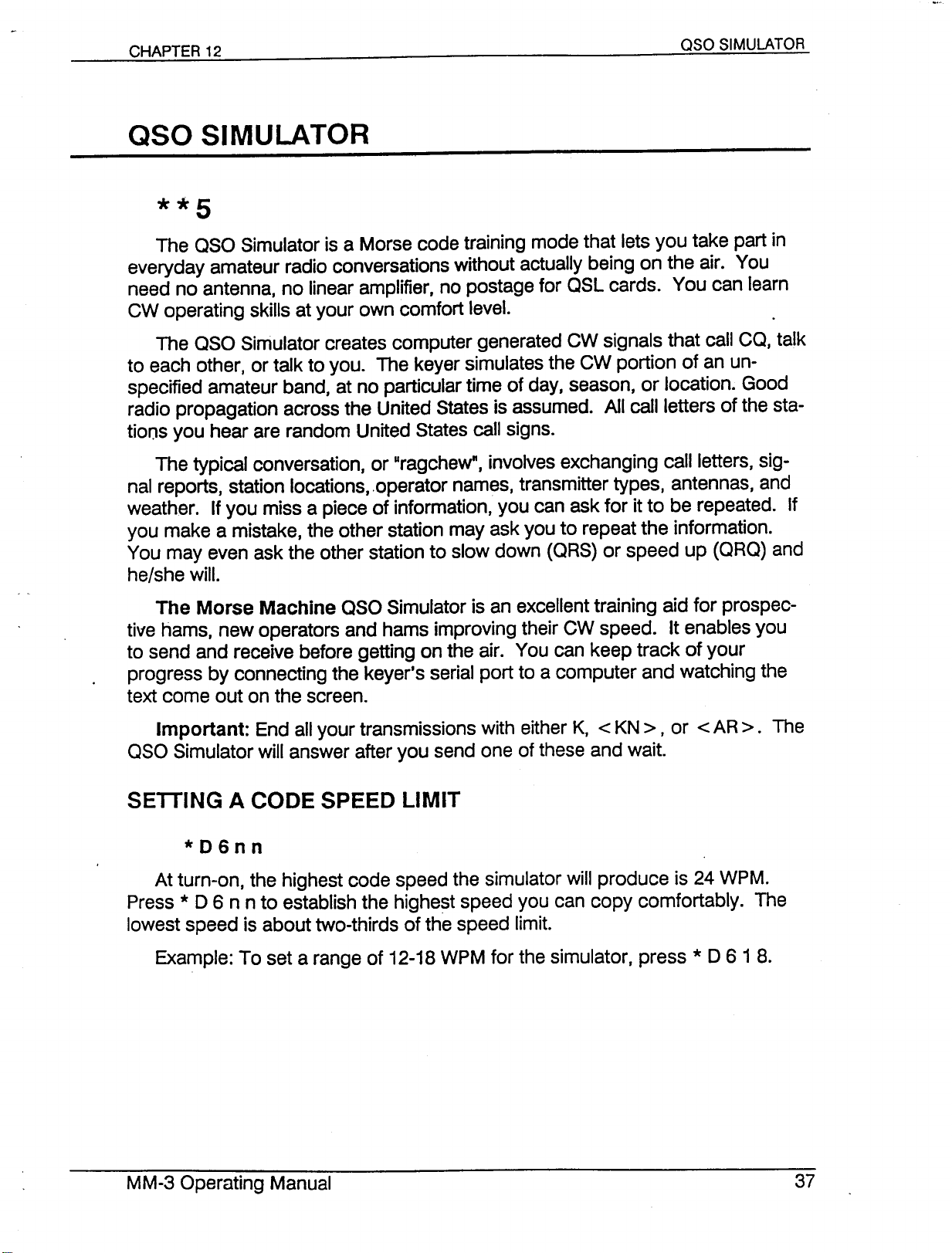
*D6nn
At turn-on, the highest code speed the simulator will produce is 24 WPM.
Press * D 6 n n to establish the highest speed you can copy comfortably. The
lowest speed is about two-thirds of the speed limit.
Example: To set a range of 12-18 WPM for the simulator, press * D 61 8.
The
Page 39
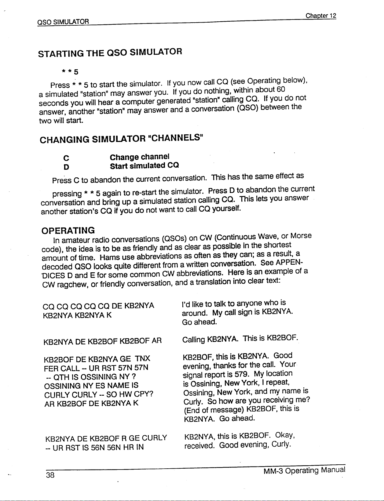
Press * * 5 to start the simulator. If you now call CO (see Operating below),
a simulated "station" may answer you. If you do nothing, within about 60
seconds you will hear a computer generated "station" calling CO. If you do not
answer, another "station" may answer and a conversation
two will start.
Change channel
Start simulated CO
Press C to abandon the current conversation. This has the same effect as
pressing * * 5 again to re-start the simulator. Press D to abandon the current
conversation and bring up a simulated station calling CO. This lets you answer
another station's CO if you do not want to call CO yourself.
(050)
between the
OPERATING
In amateur radio conversations (OSOs) on CW (Continuous Wave, or Morse
code), the idea is to be as friendly and as clear as possible in the shortest
amount of time. Hams use abbreviations as often as they can; as a result, a
decoded
DICES D and E for some common CW abbreviations. Here is an example of a
CW ragchew, or friendly conversation, and a translation into clear text:
050
looks quite different from a written conversation. See APPEN-
CO CO CO CO CO DE KB2NYA
KB2NYA KB2NYA K
KB2BOF DE KB2NYA GE TNX
FER CALL -- UR RST 57N 57N
-- OTH IS OSSINING NY ?
OSSINING NY ES NAME IS
CURLY CURLY -- SO HW CPY?
AR KB2BOF DE KB2NYA K
KB2NYA DE KB2BOF R GE CURLY
-- UR RST IS 56N 56N HR IN
I'd like to talk to anyone who is
around. My call sign is KB2NYA
Go ahead.
CalJing KB2NYA This is KB2BOF.
KB2BOF, this is KB2NYA. Good
evening, thanks for the call. Your
signal report is 579. My location
is Ossining, New York, I repeat,
Ossining, New York, and my name is
Curly. So how are you receiving me?
(End of message) KB2BOF, this is
KB2NYA Go ahead.
KB2NYA, this is KB2BOF. Okay,
received. Good evening, Curly.
Page 40
aso SIMULATOR
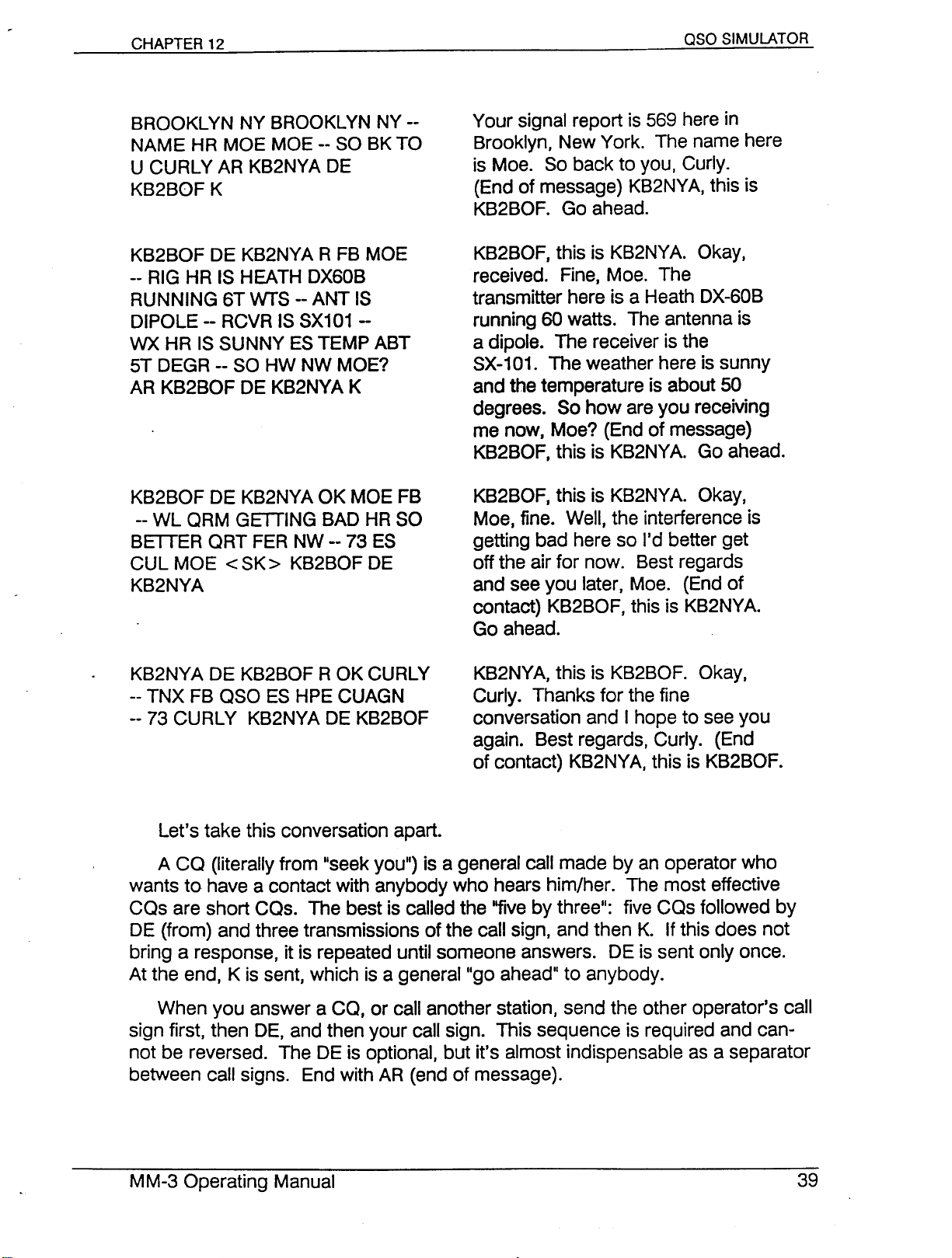
BROOKLYN NY BROOKLYN NY --
NAME HR MOE MOE -- SO BK TO
U CURLY AR KB2NYA DE
KB2BOF K
KB2BOF DE KB2NYA R FB MOE
-- RIG HR IS HEATH DX60B
RUNNING 6T wrs --ANT IS
DIPOLE -- RCVR IS SX101 -
WX HR IS SUNNY ES TEMP ABT
5T DEGR -- SO HW NW MOE?
AR KB2BOF DE KB2NYA K
KB2BOF DE KB2NYA OK MOE FB
-- WL ORM GETTING BAD HR SO
BETTER ORT FER NW -- 73 ES
CUL MOE<SK>KB2BOF DE
KB2NYA
Your signal report is 569 here in
Brooklyn, New York. The name here
is Mae. So back to you, Curly.
(End of message) KB2NYA, this is
KB2BOF. Go ahead.
KB2BOF, this is KB2NYA. Okay,
received. Fine, Moe. The
transmitter here is a Heath DX-60B
running 60 watts. The antenna is
a dipole. The receiver is the
SX-101. The weather here is sunny
and the temperature is about 50
degrees. So how are you receiving
me now, Moe? (End of message)
KB2BOF, this is KB2NYA. Go ahead.
KB2BOF, this is KB2NYA. Okay,
Moe, fine. Well, the interference is
getting bad here so I'd better get
off the air for now. Best regards
and see you later, Moe. (End of
contact) KB2BOF, this is KB2NYA.
Go ahead.
KB2NYA DE KB2BOF R OK CURLY
-- TNX FB OSO ES HPE CUAGN
-- 73 CURLY KB2NYA DE KB2BOF
Let's take this conversation apart.
A CO (literally from "seek you") is a general call made by an operator who
wants to have a contact with anybody who hears him/her. The most effective
COs are short COs. The best is called the "five by three": five COs followed by
DE (from) and three transmissions of the call sign, and then K. If this does not
bring a response, it is repeated until someone answers. DE is sent only once.
At the end, K is sent, which is a general"go ahead" to anybody.
When you answer a CO, or call another station, send the other operator's call
sign first, then DE, and then your call sign. This sequence is required and can-
not be reversed. The DE is optional, but it's almost indispensable as a separator
between call signs. End with AR (end of message).
KB2NYA, this is KB2BOF. Okay,
Curly. Thanks for the fine
conversation and I hope to see you
again. Best regards, Curly. (End
of contact) KB2NYA, this is KB2BOF.
Page 41
The double dash, which sounds like the letters BT sent as one character, is
used to separate thoughts or sentences, much as the period is used in written
text. You may hear stations in real life sending periods, but the standard prac-
tice is to use the double dash. It's shorter than the period, and you can send it
repeatedly as you pause for words.
Signal reports on CW follow the RST format, which consists of three num-
bers: 1- 5 for Readability, 1-9 for Strength, and 1-9 for Tone. A detailed break-
down of each number's meaning can be found in several ARRL publications.
The best report, 599, means that the station is perfectly readable, has an ex-
tremely strong signal, and has a perfect tone. The number "9t1is frequently shor-
tened to an
Names and locations are frequently sent twice. Actual radio conrntions:are
worse than what the keyer simulates, so if you repeat important information'the
other operator has a better chance of copying everything.
At the end of a transmission, send < AR >, his/her call sign DE your call sign,
K. You could send < KN > instead of K, which would mean you don't want
anybody to break in on your aso, but many operators really wouldn't mind the
unlikely event of a third party breaking in. If you use < KN >, remember to send
it as one character, not the two separate characters K and N.
"WI -
reports of 5NN are commonplace.
Some hams use tlBK TO Uti Clback to
plies the transmission will be ending shortly, so get ready to send. Critics of tlBK
TO
un
prefer to use "SO HW?" or "HW NW?", meaning how are you copying
(receiving) my signal, fully expecting a response like tlUR SIGS FB".
When you send numbers, you can save some time by abbreviating O's as
T's. Exception: In call signs such as KAOXXXyou must send the full
On the last transmission from each side of a aso, goodbyes are said and
then the sign < SK > is sent instead of < AR >. This is the End of Contact signal,
meaning the conversation is over.
So far ham conversations must seem a bit mechanical. In real life, some
asos consist of exchanging names, locations, ham gear, weather, and nothing
else, but many asos have more substance. For the first few exchanges, that
stiff format is useful, but then comes the opportunity for transmissions to reflect
the operator's personality, interests, feelings, and opinions. Pleasant ragchews
come from the exchange of ideas. You might expand upon something the other
operator has said, or ask questions to follow up on what he/she has said.
Usten to some asos for a while before transmitting. Notice the format of the
conversations between stations. When you feel ready, answer a ca. The
simulator decides you are finished sending a transmission after you send either
a K (go ahead), a < KN > (go only), or <AR> (end of transmission), and then
pause for a certain length of time. If you pause too long after a K in the middle of
your transmission, the other station might interrupt you. If you are getting inter-
YOU
11
)
as a transitional phrase which im-
o.
Page 42
rupted too often, slow down your sending speed. Remember to send K,
<
KN
>,
or<AR>at the end, because the other operator is waiting for it.
Now that you have become used to the ragchew format, change to a clear
channel and try calling CO yourself. If you don't get an answer, keep trying.
Enjoy your OSO.
#
To stop the simulator temporarily, press the#key. The Morse code stops
while the keyer idles in OSO Simulator mode. Pressing
simulator resume. To use the MM-3 as an ordinary keyer, press"· 3.
The transmitter keying outputs are normally disabled in the QSO
SIMULATOR mode. To enable the outputs, press •*8 to toggle transmitting on.
#
again makes the
Page 43
OX Contest Simulator
The Contest Simulator is a Morse code training mode that brings you the ex-
citement of the
self anywhere in the world, at any time of the day you wish, and experience
shortwave amateur radio operating conditions as they would occur at that time
and place. You need no antenna, no linear a•.mplifier, no postage for OSL cards.
You can improve your CW operating skills at your own comfort level.
Before starting the Contest Simulator, you go through a simple procedure of
setting the keyer's internal clock for the simulated time of day at which you. wish
to start the contest. Once you are operating, you can change bands'whenY-you
wish. If the simulator decides that the selected band is normally open forine cur-
rent time of day, you will hear computer generated CW signals. The signals are
working each other or calling CO. Some are even talking with stations in your
skip zone, which you cannot hear.
After you complete each contact, the simulator can print a log entry on the
Serial Out port (see page 45, Serial Port Output). If you are using the keyer
without a terminal or computer, you can get a Morse report of your score at any
time with a keypad command.
OX
chase without actually being on the air. You can place your-
The radio propagation programmed for each band represents what you
would expect to hear on a good propagation day with an omni-directional anten-
na. The propagation follows the internal time of day that you set before the con-
test. For example, the 15- and 10- meter bands are wide open during local
daylight hours and closed at night. 160 and 80 meters are open at night and
closed during daytime hours. The simulated stations you hear (with proper
prefixes) are at distances you would expect to hear under normal condition for
the time of day and frequency band selected.
All call letters of the stations you hear are totally random (subject to the
country's callsign assignment rules). The prefixes are weighted according to the
population density, with the guarantee that for each of the 300 + countries, there
is at least on station represented.
A typical two-way contest exchange involves call letters, signal reports and
COWW zones. If you miss a piece of information, you can ask for it to be
repeated. If you make a mistake, the other station may ask you to repeat the in-
formation. You may even ask the other station to slow down (ORS) or speed up
(ORO).
CONTEST SIMULATOR COMMANDS:
*D1ann
*D2bnnn
*D3nn
Latitude
Longitude
Hour
(UTe)
Page 44
OX Contest Simulator
These commands set the time and place for the contest. Each of these com-
mands also sets your contest score to zero.
To enter your contest location, you need to know your latitude and longitude
to the nearest whole degree. Set your latitude and longitude with the * D 1 and
* D 2 commands. On the right edge of the keypad the keys from top to bottom
are A, B, C and D. These keys have additional functions of North, East, West
and South respectively, for setting the latitude and longitude.
The range of "nn" for latitude is 00 to 90. Longitude "nnn" ranges from 000 to
180. The default coordinates are for Washington, DC: 39 North by 77 West.
Example: To set coordinates of 48 degrees North by 122 degrees West
(Seattle, WA), the commands are*D 1 A 4 8 and*.D 2 C 1 2 2.
To set coordinates of 1 degree South by 37 degrees East
(Nairobi, Kenya), the commands are * DiD
a
degrees latitude is either * D 1 A 0 0 or * D 1
a
degrees longitude is either * D 2
180 degrees longitude is either * D 2 B 1 8aor * 0 2 C 1 8
BOO
a
1 and * D 2 B 037.
a
or
'*
D 2 C
0
a o.
a a o.
O.
Set the starting time of the contest with the * 0 3 command. "nn" is the hour
in UTC, 00-23. As the contest progresses, the internal time of day advances in
real time, causing simulated radio conditions to change. The time of day advan-
ces as long as the keyer is on, no matter what the keyer's operating mode. The
time is saved when the keyer is off, and resumes where it left off when the keyer
is turned on again. The default time of day is * D 3
* *
4 Start the contest simulator
Press * * 4 to start the contest. Usten to some OSOs for a while before trans-
mitting. Notice the patterns in the contest exchanges you hear. The contest ex-
change is RST and COWW zone, usually run together (e.g., 59903). Some of
the numbers are abbreviated in the interest of faster exchanges:
a a
(0000 UTC).
T=O
A=1
N=9
There are two ways to go in a contest. In the Hunt and Pounce strategy you
wait for station to call CO and you answer them. In the Call CO Forever tech
nique you stake out a frequency (simulator 'Ichannel") and call CO for hours,
ting the stations come to you. Newcomers should listen to a COer for a while
and then call it.
let-
You might not copy the complete callsign of a station that answers your CO.
This is not a problem; just send the station's suffix if you heard it, then the ex-
change (RST zone). Most of the time the station will come back to you. You
must, however, acknowledge callers by sending at least part of their callsign, or
they will not come back to you.
Page 45
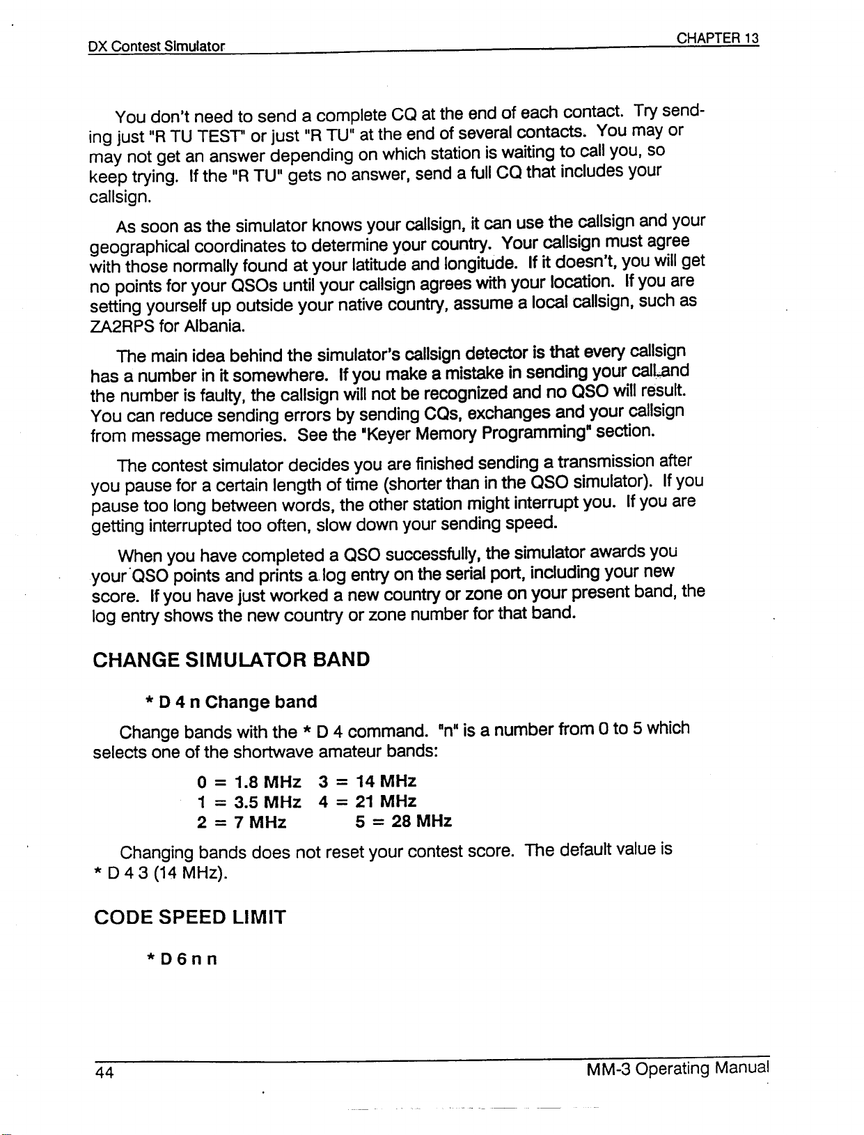
You don't need to send a complete CO at the end of each contact. Try send-
ing just "RTU TEST" or just "R TU" at the end of several contacts. You mayor
may not get an answer depending on which station is waiting to call you, so
keep trying. If the "RTU" gets no answer, send a full CO that includes your
callsign.
As soon as the simulator knows your callsign, it can use the callsign and your
geographical coordinates to determine your country. Your callsign must agree
with those normally found at your latitude and longitude. If it doesn't, you will get
no points for your OSOs until your callsign agrees with your location. If you are
setting yourself up outside your native country, assume a local callsign, such as
ZA2RPS for Albania.
The main idea behind the simulator's callsign detector is that every callsign
has a number in it somewhere. If you make a mistake in sending your caJL,and
the number is faUlty, the callsign will not be recognized and no aso will result.
You can reduce sending errors by sending COs, exchanges and your callsign
from message memories. See the -Keyer Memory Programming" section.
The contest simulator decides you are finished sending a transmission after
you pause for a certain length of time (shorter than in the aso simulator). If you
pause too long between words, the other station might interrupt you. If you are
getting interrupted too often, slow down your sending speed.
When you have completed a asa successfully, the simulator awards you
your "aSa points and printsalog entry on the serial port, including your new
score. If you have just worked a new country or zone on your present band, the
log entry shows the new country or zone number for that band.
* 0 4 n Change band
Change bands with the * D 4 command. "nil is a number from 0 to 5 which
selects one of the shortwave amateur bands:
o
=
1.8 MHz 3
1=3.5 MHz 4
2
=
7 MHz 5=28 MHz
Changing bands does not reset your contest score. The default value is
*
043 (14MHZ).
=
14 MHz
=
21 MHz
Page 46
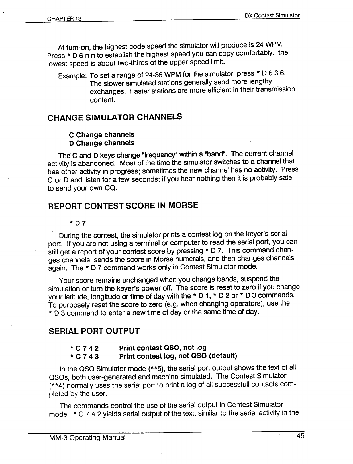
At turn-on, the highest code speed the simulator will produce is 24 WPM.
Press * D 6 n n to establish the highest speed you can copy comfortably. the
lowest speed is about two-thirds of the upper speed limit.
Example: To set a range of 24-36WPM for the simulator, press * D 6 3 6.
The slower simulated stations generally send more lengthy
exchanges. Faster stations are more efficient in their transmission
content.
C Change channels
o Change channels
The C and D keys change "'equency" within a "band". The current channel
activity is abandoned. Most of the time the simulator switches to a channel that
has other activity in progress; sometimes the new channel has no activity. Press
C or D and listen for a few seconds; if you hear nothing then it is probably safe
to send your own ca.
*07
During the contest, the simulator prints a contest log on the keyer's serial
port. If you are not using a terminal or computer to read the serial port, you can
still get a report of your contest score by pressing * D7. This command chan-
ges channels, sends the score in Morse numerals, and then changes channels
again. The * D 7 command works only in Contest Simulator mode.
Your score remains unchanged when you change bands, suspend the
simulation or turn the keyer's power off. The score is reset to zero if you change
your latitude, longitude or time of day with the*D 1, * D 2 or*D 3 commands.
To purposely reset the score to zero (e.g. when changing operators), use the
* D 3 command to enter a new time of day or the same time of day.
* C 742 Print contest aso, not log
* C 7 4 3 Print contest log, not aso (default)
In the aso Simulator mode (**5), the serial port output shows the text of all
asos, both user-generated and machine-simulated. The Contest Simulator
(**4) normally uses the serial port to print a log of all successfull contacts com-
pleted by the user.
The commands control the use of the serial output in Contest Simulator
mode.*C 7 4 2 yields serial output of the text, similar to the serial activity in the
Page 47
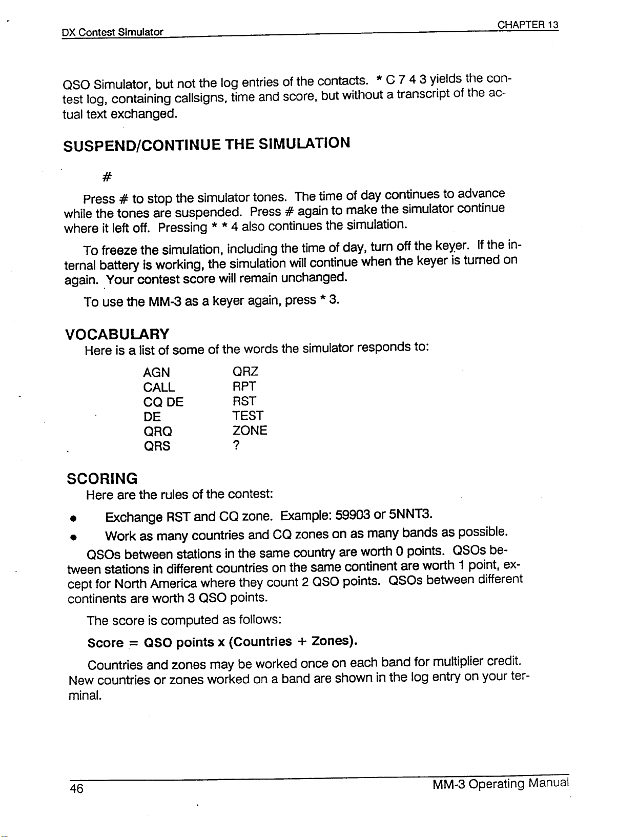
OSO Simulator, but not the log entries of the contacts. * C 7 4 3 yields the con-
test log, containing callsigns, time and score, but without a transcript of the ac-
tual text exchanged.
#
Press#to stop the simulator tones. The time of day continues to advance
while the tones are suspended. Press#again to make the simulator continue
where it left off. Pressing * * 4 also continues the simulation.
To freeze the simulation, including the time of day, turn off the key.er. If the in-
ternal battery is working, the simulation will continue when the keyer is turned on
again .. Your contest score will remain unchanged.
To use the MM-3 as a keyer again, press *3.
VOCABULARY
Here is a list of some of the words the simulator responds to:
AGN
CALL
CODE
DE
ORO
ORS
ORZ
RPT
RST
TEST
ZONE
?
SCORING
Here are the rules of the contest:
• Exchange RST and CO zone. Example: 59903 or 5NNT3.
• Work as many countries and CO zones on as many bands as possible.
OSOs between stations in the same country are worth 0 points. OSOs be-
tween stations in different countries on the same continent are worth 1 point, ex-
cept for North America where they count 2 OSO points. OSOs between different
continents are worth 3 OSO points.
The score is computed as follows:
Score
Countries and zones may be worked once on each band for multiplier credit.
New countries or zones worked on a band are shown in the log entry on your ter-
minal.
=
aso points x (Countries + Zones).
Page 48
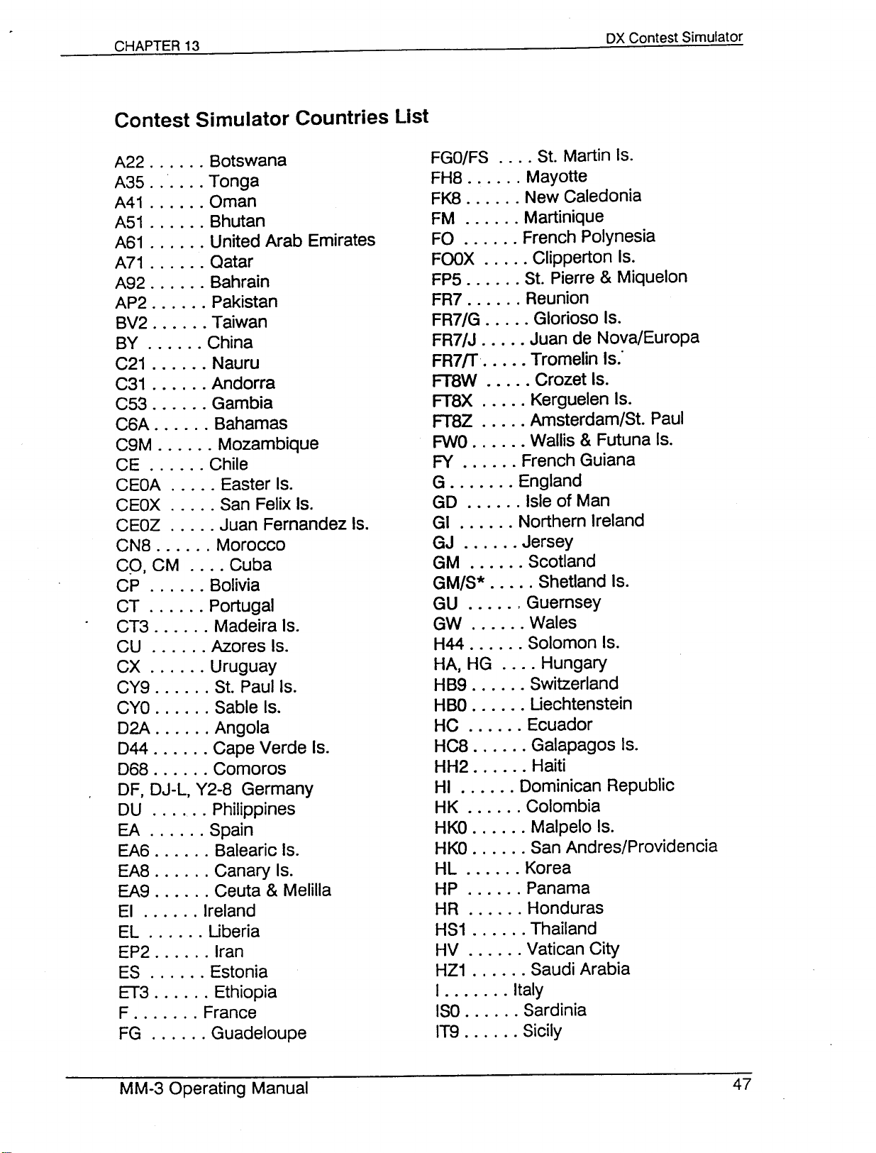
DX Contest Simulator
A22 Botswana
A35. " Tonga
A41 Oman
A51 Bhutan
A61 United Arab Emirates
A71 Qatar
A92 Bahrain
AP2 Pakistan
BV2 Taiwan
BY China
C21 Nauru
C31 Andorra
C53 Gambia
C6A Bahamas
C9M Mozambique
CE Chile
CEOA Easter Is.
CEOX San Felix Is.
CEOZ Juan Fernandez Is.
CN8 Morocco
CO, CM Cuba
CP Bolivia
CT Portugal
CT3 Madeira Is.
CU Azores Is.
CX Uruguay
CY9 S1,Paul Is.
CYO Sable Is.
02A Angola
044 Cape Verde Is.
068 Comoros
OF, OJ-L, Y2-8 Germany
OU Philippines
EA Spain
EA6 Balearic Is.
EA8 Canary Is.
EA9 Ceuta & Melilla
EI Ireland
EL Uberia
EP2 Iran
ES Estonia
ET3 Ethiopia
F France
FG Guadeloupe
FGO/FS S1,Martin Is.
FH8 Mayotte
FK8 New Caledonia
FM Martinique
FO '" French Polynesia
FOOX Clipperton Is.
FP5 S1,Pierre & Miquelon
FR7 Reunion
FR7/G Glorioso Is.
FR7/J Juan de Nova/Europa
FR7ff Tromelin Is:
FT8W Crozet Is.
FT8X Kerguelen Is.
FT8Z Amsterdam/S1, Paul
FWO Wallis & Futuna Is.
FY French Guiana
G England
GO Isle of Man
GI Northern Ireland
GJ Jersey
GM Scotland
GM/S* Shetland Is.
GU ' Guernsey
GW Wales
H44 Solomon Is.
HA, HG Hungary
HB9 Switzerland
HBO Uechtenstein
HC Ecuador
HC8 Galapagos Is.
HH2 Haiti
HI Dominican Republic
HK Colombia
HKO Malpelo Is.
HKO San Andres/Providencia
HL ., Korea
HP Panama
HR Honduras
HS1 Thailand
HV Vatican City
HZ1 Saudi Arabia
I Italy
ISO Sardinia
IT9 Sicily
Page 49
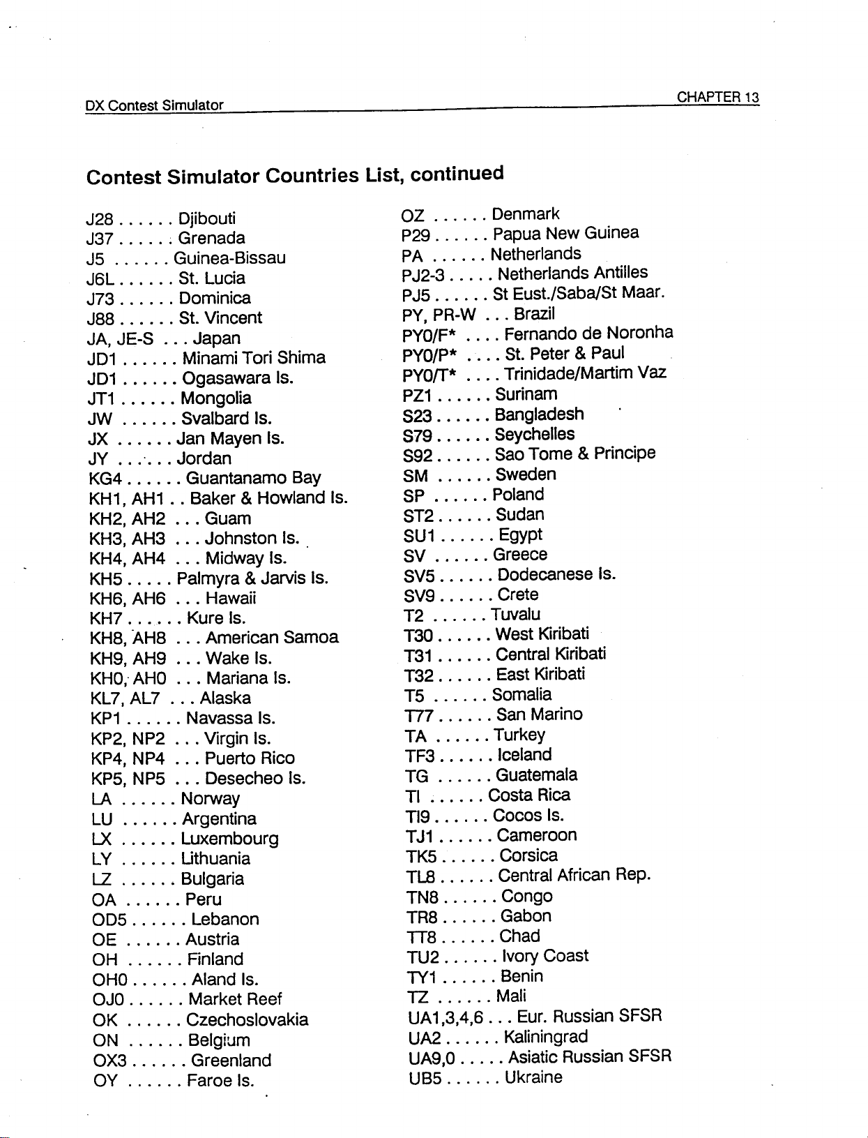
Contest Simulator Countries List, continued
J28 Djibouti
J37 ; Grenada
J5 Guinea-Bissau
J6L St. Lucia
J73 Dominica
J88 St. Vincent
JA,JE-S Japan
JD1 Minami Tori Shima
JD1 Ogasawara Is.
JT1 Mongolia
JW Svalbard Is.
JX Jan Mayen Is.
JY
0 •••
Jordan
KG4 Guantanamo Bay
KH1, AH1 .. Baker&Howland Is.
KH2, AH2 ... Guam
KH3, AH3 '" Johnston Is.
KH4, AH4 ... Midway Is.
KH5 ..... Palmyra & Jarvis Is.
KH6, AH6 Hawaii
KH7 Kure Is.
KH8, AH8 American Samoa
KH9, AH9 Wake Is.
KHO,oAHO Mariana Is.
KL7, AL7 Alaska
KP1 Navassa Is.
KP2, NP2 Virgin Is.
KP4, NP4 Puerto Rico
KP5, NP5 Desecheo Is.
LA Norway
LU Argentina
LX Luxembourg
LY Uthuania
LZ Bulgaria
OA Peru
OD5 Lebanon
OE Austria
OH Finland
OHO Aland Is.
OJO Market Reef
OK Czechoslovakia
ON Belgium
OX3 Greenland
OY Faroe Is.
OZ Denmark
P29 Papua New Guinea
PA Netherlands
PJ2-3 Netherlands Antilles
PJ5 St Eust./Saba/St Maar.
PY, PR-W Brazil
PYO/F* Fernando de Noronha
PYO/P* St. Peter & Paul
PYOrr* Trinidade/Martim Vaz
PZ1 Surinam
S23 Bangladesh
S79 . . . . .. Seychelles
S92 Sao Tome&Principe
SM Sweden
SP Poland
ST2 Sudan
SU1 Egypt
SV Greece
SV5 Dodecanese Is.
SV9 Crete
T2 Tuvalu
T30 West Kiribati
T31 Central Kiribati
T32 East Kiribati
T5 Somalia
T77 San Marino
TA Turkey
TF3 Iceland
TG Guatemala
TI Costa Rica
TI9 Cocos Is.
TJ1 Cameroon
TK5 Corsica
TLB Central African Rep.
TN8 Congo
TR8 Gabon
TI8 Chad
TU2 Ivory Coast
TY1 Benin
TZ Mali
UA1,3,4,6 Eur. Russian SFSR
UA2 Kaliningrad
UA9,O Asiatic Russian SFSR
UB5 Ukraine
Page 50
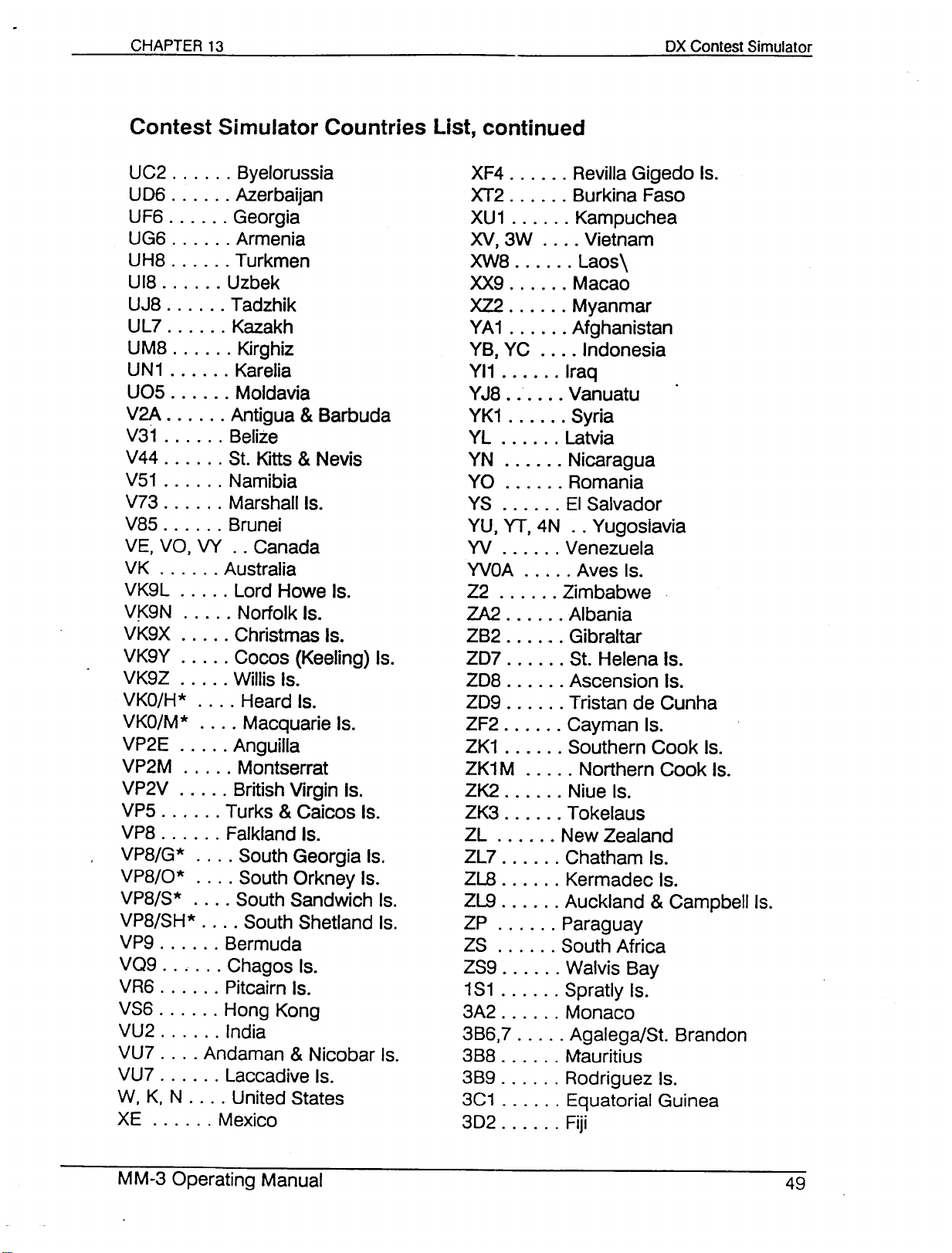
UC2 Byelorussia
U06 Azerbaijan
UF6 Georgia
UG6 Armenia
UH8 Turkmen
U18 Uzbek
UJ8 Tadzhik
UL7 Kazakh
UM8 Kirghiz
UN1 . . . . . . Karelia
U05 Moldavia
V2A Antigua&Barbuda
V31 Belize
V44 St. Kitts&Nevis
V51 Namibia
V73 Marshall Is.
V85 Brunei
VE, VO, VY .. Canada
VK . . . . . . Australia
VK9L Lord Howe Is.
VK9N Norfolk Is.
VK9X Christmas Is.
VK9Y Cocos (Keeling) Is.
VK9Z Willis Is.
VKO/H* Heard Is.
VKO/M* Macquarie Is.
VP2E Anguilla
VP2M Montserrat
VP2V British Virgin Is.
VP5 Turks & Caicos Is.
VP8 Falkland Is.
VP8/G* South Georgia Is.
VP8/0* South Orkney Is.
VP8/S* South Sandwich Is.
VP8/SH* South Shetland Is.
VP9 Bermuda
VQ9 Chagos Is.
VR6 Pitcairn Is.
VS6 Hong Kong
VU2 India
VU7 Andaman & Nicobar Is.
VU7 Laccadive Is.
W, K, N United States
XE Mexico
XF4 Revilla Gigedo Is.
XT2 Burkina Faso
XU1 Kampuchea
XV,3W Vietnam
XW8 Laos\
XX9 Macao
XZ2 Myanmar
YA1 Afghanistan
YB, YC Indonesia
YI1 Iraq
YJ8 Vanuatu
YK1 Syria
YL Latvia
YN Nicaragua
YO Romania
YS EI Salvador
YU, YT, 4N .. Yugoslavia
YV ., Venezuela
YVOA Aves Is.
Z2 Zimbabwe
ZA2 Albania
ZB2 Gibraltar
Z07 St. Helena Is.
Z08 Ascension Is.
Z09 Tristan de Cunha
ZF2 Cayman Is.
ZK1 Southern Cook Is.
ZK1M Northern Cook Is.
ZK2 Niue Is.
ZK3 Tokelaus
ZL New Zealand
ZL7 Chatham Is.
ZL8 Kermadec Is.
ZL9 Auckland & Campbell Is.
ZP Paraguay
ZS South Africa
ZS9 Walvis Bay
1S1 Spratly Is.
3A2 Monaco
3B6,7 Agalega/St. Brandon
3B8 Mauritius
3B9 Rodriguez Is.
3C1 Equatorial Guinea
302 Fiji
Page 51
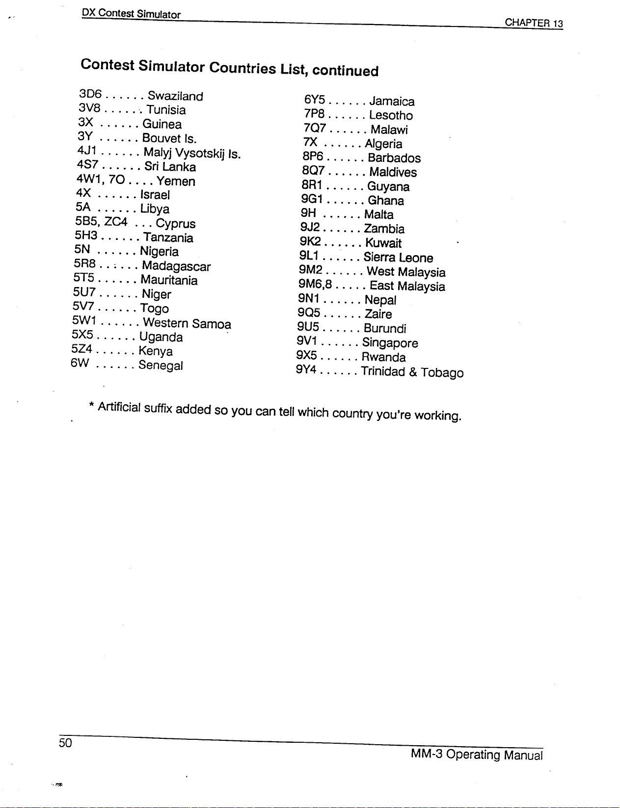
306 Swaziland
3V8 ".Tunisia
3X Guinea
3Y Bouvet Is.
4J1 Malyj Vysotskij Is.
4S7 Sri Lanka
4W1, 70 Yemen
4X Israel
5A Ubya
5B5, ZC4 Cyprus
5H3 Tanzania
5N Nigeria
5R8 .. ; Madagascar
5T5 Mauritania
5U7 Niger
5V7 Togo
5W1 Western Samoa
5X5 Uganda .
5Z4 Kenya
6W Senegal
6Y5 Jamaica
7P8 Lesotho
707 Malawi
7X Algeria
8P6 Barbados
807 Maldives
8R1 Guyana
9G1 Ghana
9H Malta
9J2 Zambia
9K2 Kuwait
9L1 Sierra Leone
9M2 West Malaysia
9M6,8 East Malaysia
9N1 Nepal
905 Zaire
9U5 Burundi
9V1 Singapore
9X5 Rwanda
9Y4 ' . Trinidad&Tobago
Page 52
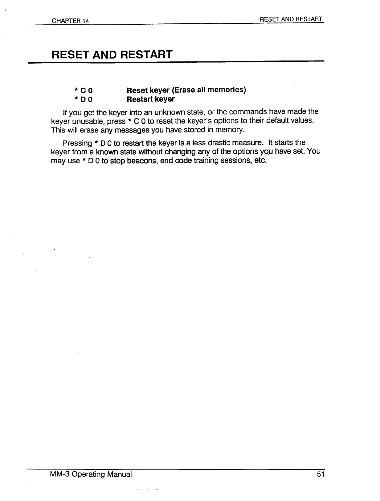
RESET AND RESTART
*
C0 Reset keyer (Eraseall memories)
*
0
0 Restartkeyer
If you get the keyer into an unknown state, or the commands have made the
keyer unusable, press *C 0 to reset the keyer's options to their default values.
This will erase any messages you have stored in memory.
Pressing *
keyer from a known state without changing any of the options you have set. You
may use *
0
0 to restart the keyer is a less drastic measure. It starts the
0
0 to stop beacons, end code training sessions, etc.
Page 53
INTERESTING USES FOR THE MORSE MACHINE
Connect the serial port to a computer. The Morse Machine will echo the
Trainer code practice text to the screen so you can check your copy. Everything
you hear and send on the aso and
put and show up on your computer screen.
Connect the serial port to a computer, set up the ASCII/MORSE CON-
VERTER mode, and upload a text file from the computer to the keyer. This gives
you a code practice session with plain English text at a constant speed. When
the file is finished, compare your copy with the actual text in the computer.
With The Morse Machine, packet radio is now accessible to the blind
without expensive ASCII-to-voice synthesizers. Just set up the keyer as a ter-
minal connected to a packet TNC. The keyer also is useful as a highly portable
terminal to operate packet radio in the field.
OX
Simulators also can go to the serial out-
Connect an AEA CP-1 or CP-100 Computer Patch to your receiver's audio.
Connectthe digital output from the CP-1 to The Morse Machine's dash input.
Press *C 5 to set Straight Key mode. Connect the keyer's serial port to a com-
puter. You now have a Morse reader.
Slow down the Morse code you hear on the air by connecting the keyer's
serial port to an AEA PK-232 data controller. Set up the PK-232 in Morse opera-
tion, find a fast Morse signal, use the PK-232 to convert the Morse to ASCII, and
use the MM-3 to convert the ASCII back to Morse code, only slower.
Generate on-the-air code practice by connecting the keyer to a transmitter,
setting the keyer to the ASCII/MORSE CONVERTER mode and uploading a text
file from a computer. Or set the keyer to Trainer mode, then press * * 8 to ac-
tivate the Transmit output. Put four-letter words on the air, and remember to
identify every 10 minutes.
Page 54
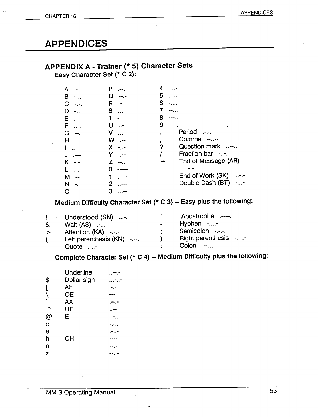
APPENDICES
APPENDIX A - Trainer (* 5) Character Sets
Easy Character Set (* C 2):
APPENDICES
A -
8 ...
C
D ..
E
F ...
G .
H
I ..
J .
K
L ...
M --
N -.
o
Medium Difficulty Character Set (* C 3) -- Easy plus the following:
Understood (SN)
&
>
(
II
Wait (AS)
Attention (KA)
Left parenthesis (KN)
Quote
.
..
P ..
Q
R ..
S
T -
U ..
V ...
W .-
X ..
y .
Z ..
4 ....
5
6
7
8
9
Period ...
Comma --..--
Question mark .
Fraction bar - .
End of Message (AR)
o
1 .
2 ..
3 ...
....
.
...
..
)
.
End of Work (SK)
Double Dash (81)
Apostrophe
Hyphen
Semicolon
Right parenthesis
Colon
---
-
...
....
-
...
.
----
.
..
Complete Character Set (* C 4) - Medium Difficulty plus the following:
e
h
n
z
$
[
\
]
A
@
c
Underline
Dollar sign
AE
OE
AA
UE
E
CH
..
.....
..
---
....
...
..
--
.
-
-
Page 55
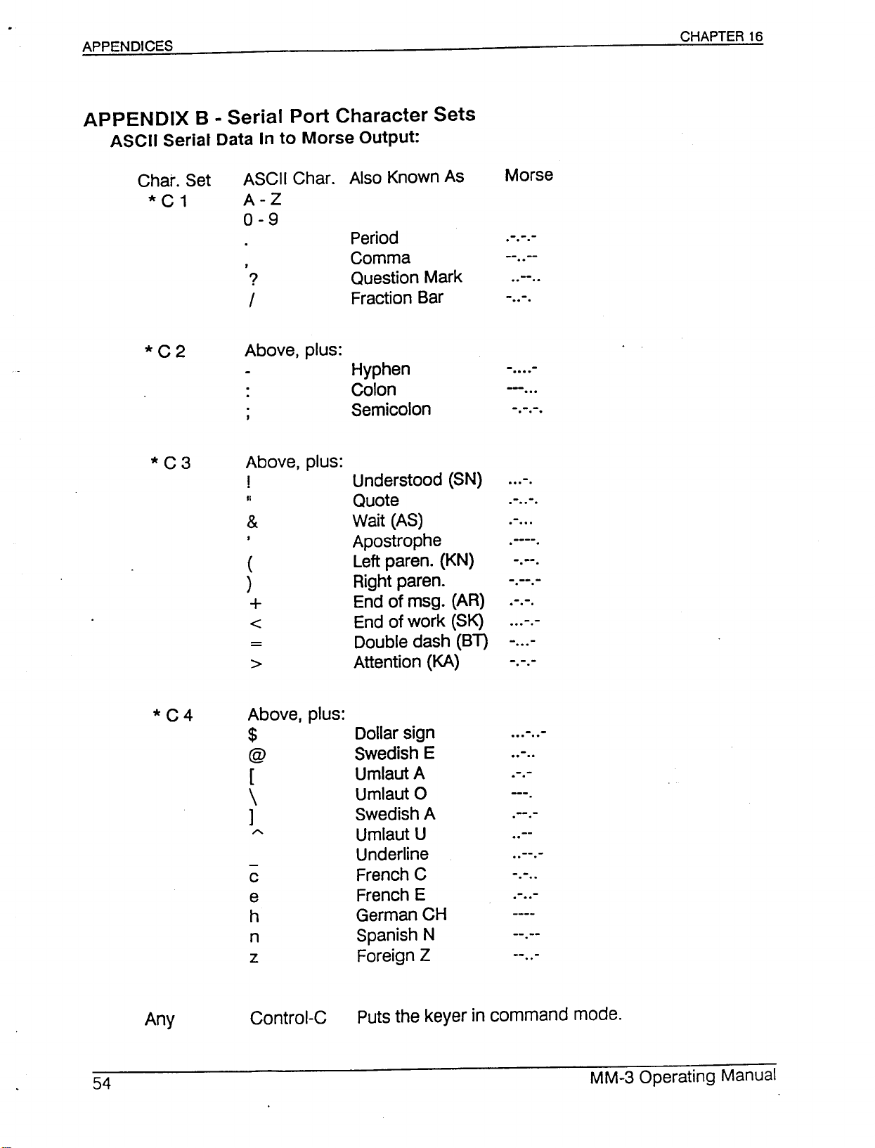
APPENDIX 8 - Serial Port Character Sets
ASCII Serial Data In to Morse Output:
Char. Set
*C1
*C2
*C3
ASCII Char.
A-Z
0-9
?
f
Above, plus:
Above, plus:
!
II
&
(
)
+
<
=
>
Also Known As
Period
Comma
Question Mark
Fraction Bar
Hyphen
Colon
Semicolon
Understood (SN)
Quote
Wait (AS)
Apostrophe
Left paren. (KN)
Right paren.
End of msg. (AR)
End of work (SK)
Double dash (BT)
Attention (KA)
Morse
·
..
..
..--..
...
....
-
-
...
--
...
....
·...
·
...
----
·
.
·
..
....
-
-
".
·
.
*C4
Above, plus:
$
@
[
\
]
A
c French C
e French E
h
n
z
Dollar sign .....
Swedish E
Umlaut A
Umlaut 0
Swedish A
Umlaut U
Underline
German CH
Spanish N
Foreign Z
....
·
.
---
·
·
..
..
..
Page 56
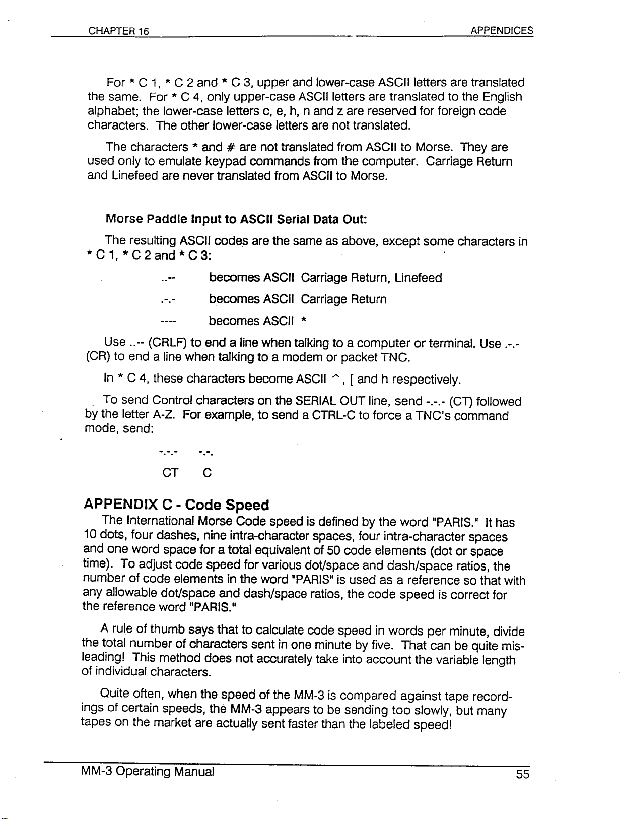
For * C 1, * C 2 and * C 3, upper and lower-case ASCII letters are translated
the same. For * C4,only upper-case ASCII letters are translated to the English
alphabet; the lower-case letters c, e, h, nand z are reserved for foreign code
characters. The other lower-case letters are not translated.
The characters*and#are not translated from ASCII to Morse. They are
used only to emulate keypad commands from the computer. Carriage Return
and Linefeed are never translated from ASCII to Morse.
Morse Paddle Input to ASCII Serial Data Out:
The resulting ASCII codes are the same as above, except some characters in
* C 1, * C 2 and * C 3: .
.. becomes ASCII Carriage Return, Linefeed
. . becomes ASCII Carriage Return
becomes ASCII *
Use ..-- (CRLF) to end a line when talking to a computer or terminal. Use .-.-
(CR) to end a line when talking to a modem or packet TNC.
In * C 4, these characters become ASCII
A, [
and h respectively.
. To send Control characters on the SERIAL OUT line, send -.-.- (CT) followed
by the letter A-Z. For example, to send a CTRL-C to force a TNC's command
mode, send:
APPENDIX C - Code Speed
The International Morse Code speed is defined by the word "PARIS.11It has
10 dots, four dashes, nine intra-character spaces, four intra-character spaces
and one word space for a total equivalent of 50 code elements (dot or space
time). To adjust code speed for various doVspace and dash/space ratios, the
number of code elements in the word "PARISIIis used as a reference so that with
any allowable doVspace and dash/space ratios, the code speed is correct for
the reference word IIPARIS.u
A rule of thumb says that to calculate code speed in words per minute, divide
the total number of characters sent in one minute by five. That can be quite mis-
leading! This method does not accurately take into account the variable length
of individual characters.
Quite often, when the speed of the MM-3 is compared against tape record-
ings of certain speeds, the MM-3 appears to be sending too slowly. but many
tapes on the market are actually sent faster than the labeled speed!
Page 57
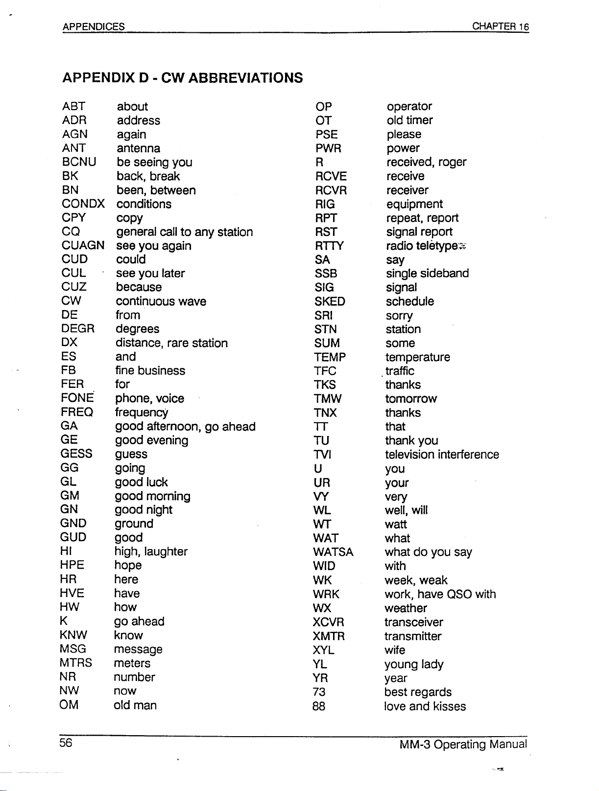
ABT
ADR
AGN
ANT
BCNU
BK
BN
CONDX
CPY
CO
CUAGN
CUD
CUL
CUZ
CW
DE
DEGR
OX
ES
FB
FER
FONE"
FREO
GA
GE
GESS
GG
GL
GM
GN
GND
GUD
HI
HPE
HR
HVE
HW
K
KNW
MSG
MTRS
NR
NW
OM
about
address
again
antenna
be seeing you
back, break
been, between
conditions
copy
general call to any station
see you again
could
see you later
because
continuous wave
from
degrees
distance, rare station
and
fine business
for
phone, voice
frequency
good afternoon, go ahead
good evening
guess
going
good luck
good morning
good night
ground
good
high, laughter
hope
here
have
how
go ahead
know
message
meters
number
now
old man
OP
OT
PSE
PWR
R
RCVE
RCVR
RIG
RPT
RST
RnY
SA
SSB
SIG
SKED
SRI
STN
SUM
TEMP
TFC
TKS
TMW
TNX
TT
TU
TVI
U
UR
VY
WL
WT
WAT
WATSA
WID
WK
WRK
WX
XCVR
XMTR
XYL
YL
YR
73
88
operator
old timer
please
power
received, roger
receive
receiver
equipment
repeat, report
signal report
radio teletype"~:
say
single sideband
signal
schedule
sorry
station
some
temperature
traffic
thanks
tomorrow
thanks
that
thank you
television interference
you
your
very
well, will
watt
what
what do you say
with
week, weak
work, have OSO with
weather
transceiver
transmitter
wife
young lady
year
best regards
love and kisses
Page 58
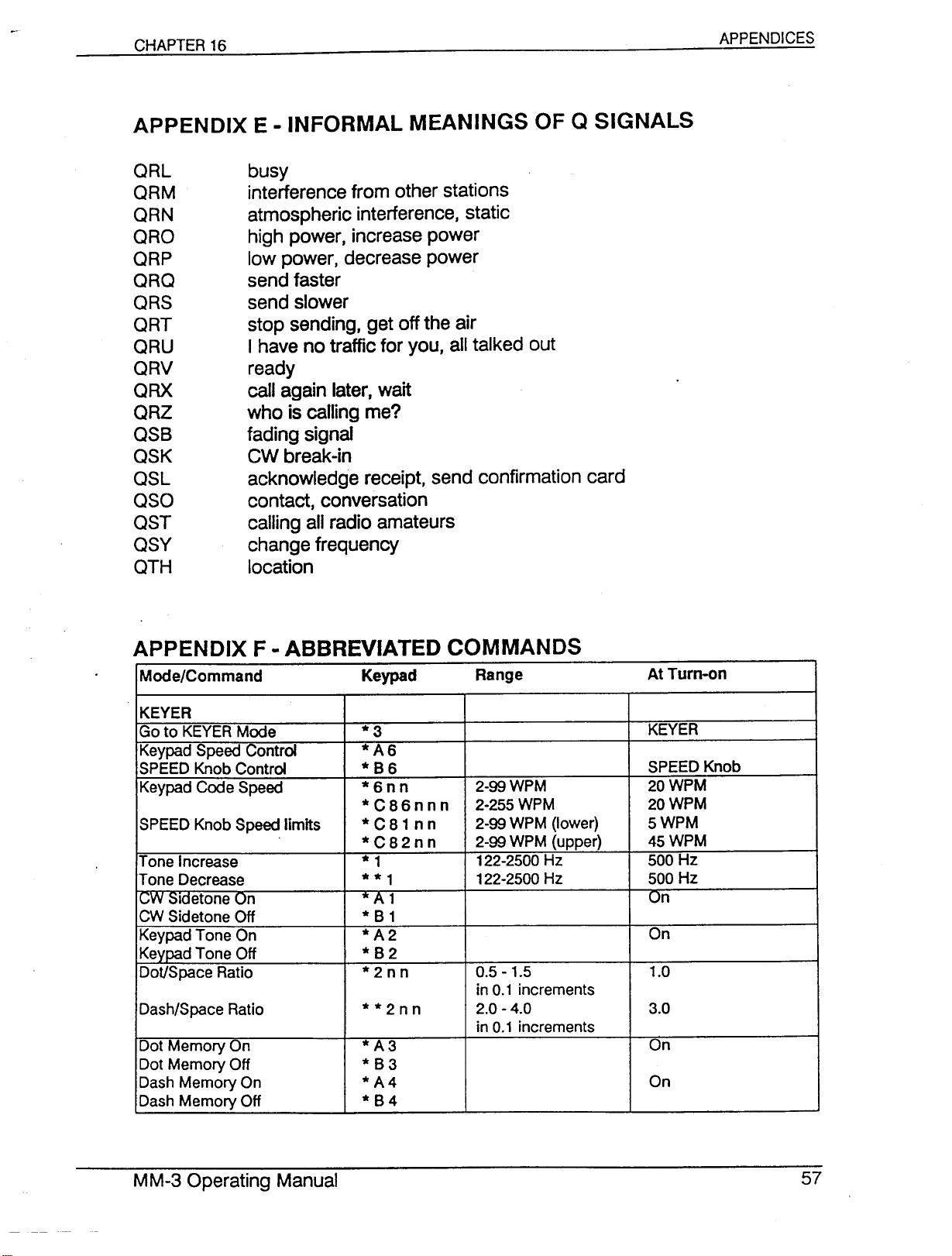
QRL busy
QRM
interferencefrom other stations
QRN atmosphericinterference.static
QRO high power.increasepower
QRP lowpower.decreasepower
QRQ sendfaster
QRS send slower
QRT stop sending.getoffthe air
QRU I haveno trafficfor you. alltalkedout
QRV ready
QRX call again later.wait
QRZ who is callingme?
QSS fadingsignal
QSK CWbreak-in
QSL acknowledgereceipt.send confirmationcard
QSO contact.conversation
QST callingallradioamateurs
QSY changefrequency
QTH location
APPENDICES
Mode/Command
KEVER
Go to KEVER Mode
Keypad Speed Control
SPEED Knob Control
Keypad Code Speed
SPEED Knob Speed limits
Tone Increase
Tone Decrease
c.;,W
::ildetone On
CW Sidetone Off
Keypad Tone On
Keypad Tone Off
DoVSpace Ratio
Dash/Space Ratio
Dot Memory On
Dot Memory Off
Dash Memory On
Dash Memory Off
Keypad
*3
*A6
*86
*6nn
*C86nnn
*C81nn
*C82nn
* 1
**1
.••.A1
*81
*A2
*82
*2nn
**2nn 2.0 - 4.0 3.0
*A3
*83
*A4 On
*84
Range
2-99 WPM 20 WPM
2-255 WPM 20 WPM
2-99 WPM (lower)
2-99 WPM (upper) 45 WPM
122-2500 Hz
122-2500 Hz
0.5 - 1.5
in 0.1 increments
in 0.1 increments
At Turn-on
KEYER
SPEED Knob
5 WPM
500 Hz
500 Hz
On
On
1.0
On
Page 59
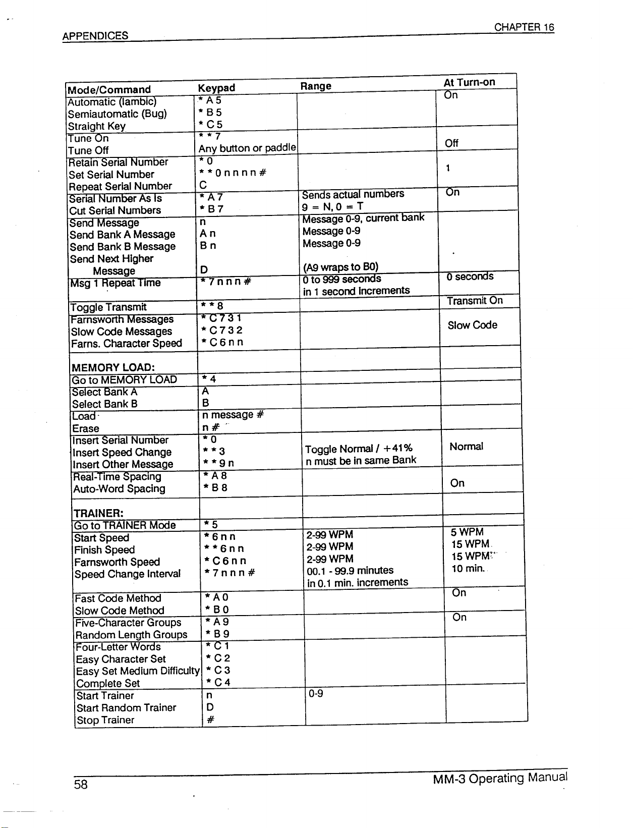
Mode/Command Keypad Range
Automatic (Iambic)
Semiautomatic (Bug)
Straight Key
Tune On
Tune Off
Retain Senal Number
Set Serial Number
Repeat Serial Number
Senal Number As Is
Cut Serial Numbers
Send Message
Send Bank A Message
Send Bank B Message
Send Next Higher
Message
IMsg 1 Repeat Time
Toggle Transmit
IFarnsworth Messages
Slow Code Messages
Farns. Character Speed
MEMORY LOAD:
Go to MEMORY LOAD
ISelect Bank A
Select Bank B
ILoad-
Erase
Insert Serial Number
Insert Speed Change
Insert Other Message
Real-lime Spacing
Auto-Word Spacing
*A5
*B5
*C5
**7
Any button or paddle
*0
**Onnnn#
C
*A7
*B7
n
An Message 0-9
Bn Message 0-9
D (A9 wraps to BO)
*7nnn#
**8
"(;731
*C732
*C6nn
*4
A
B
n message #
n:/f'
*0
**3
**9n
*A8
*B8 On
Sends actual numbers
9=N,O=T
Message 0-9, current banI<
o
to 999 seconds
in 1 second Increments
Toggle Normal
n must be in same Bank
I
+
41% Normal
At Turn-on
On
Off
1
On
o
seconas
Transmit On
Slow Code
TRAINER:
Go to TRAINER Mode
Start Speed
Finish Speed
Farnsworth Speed
Speed Change Interval
Fast Code Method
Slow Code Method
Five-Character Groups
Random Length Groups
I
Four-Letter Words
Easy Character Set
Easy Set Medium Difficulty
Complete Set
Start Trainer
Start Random Trainer
Stop Trainer
*5
*6nn 2-99 WPM 5 WPM
**6nn 2-99 WPM 15WPM
·C6nn
*7nnn#
*AO On
*BO
*A9 On
*B9
*C1
*C2
*C3
*C4
n
D
#
2-99 WPM
00.1 - 99.9 minutes
in 0.1 min. increments
0-9
15 WPM~'
10 min.
Page 60
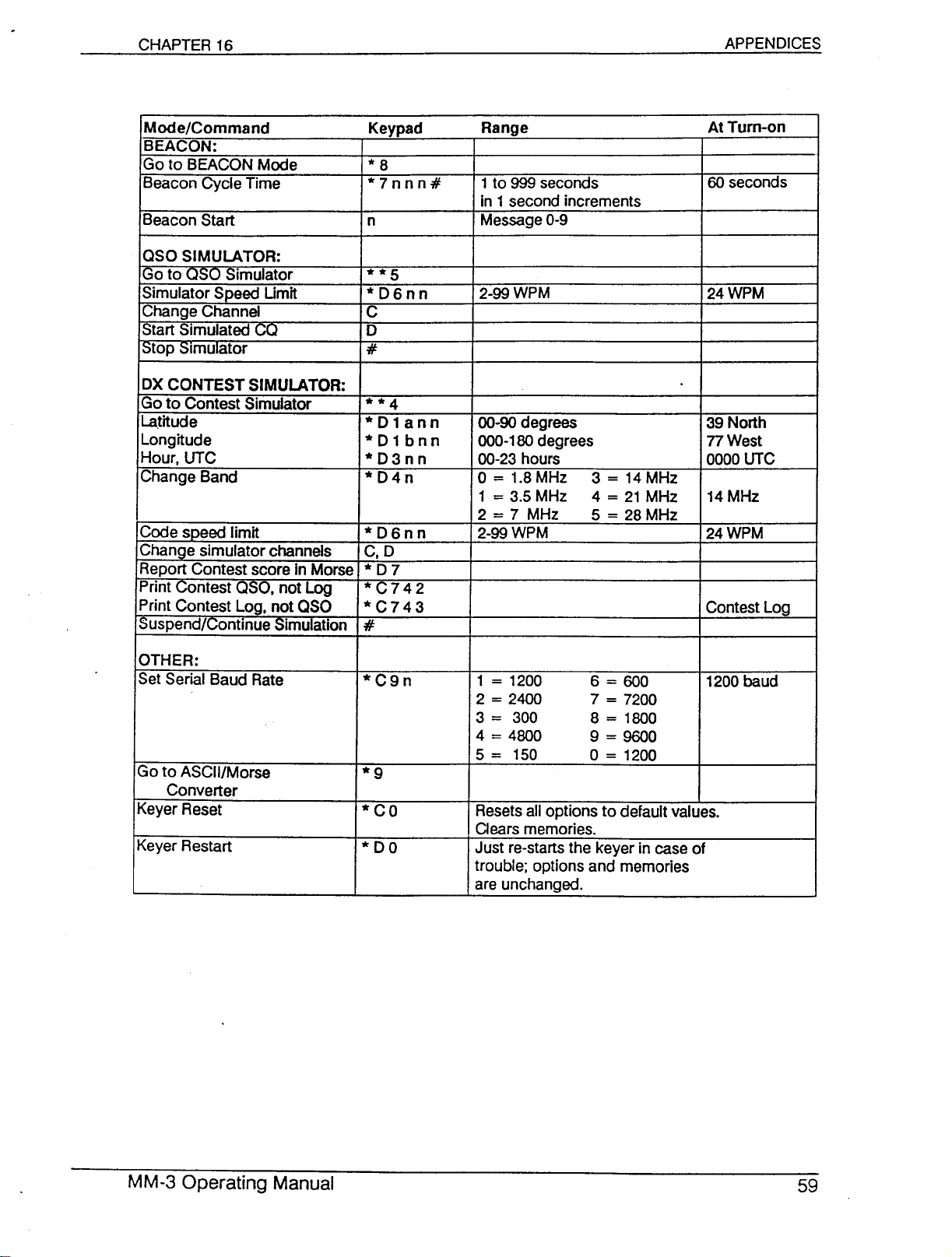
Mode/Command
BEACON:
Go to BEACON Mode
Beacon Cycle Time
Beacon Start
050
SIMULATOR:
IGoto
050
Simulator
Simulator Speed Umit
Change Channel
Start Simulated CO
~top Simulator
OXCONTEST SIMULATOR:
Go to Contest Simulator
Latitude
Longitude
Hour, UTC
Change Band
Code speed limit
Change simulator channels
Report Contest score In Morse
Print Contest
Print Contest Log, not
Suspend/Continue Simulation
aso,
not Log
aso
Keypad
*8
*7nnn#
n
**5
*06nn
C
0
#
**4
*D1ann
*01bnn
*03nn
*04n
*06nn
C,O
*07
*C742
*C743 Contest Log
#
Range
1to 999 seconds
in 1 second increments
Message0-9
2-ggWPM
00-90degrees 39 North
000-180degrees
00-23hours
0= 1.8MHz
1 = 3.5 MHz
2 = 7 MHz
2-GGWPM
3 = 14MHz
4 = 21 MHz 14MHz
5 = 28 MHz
At Turn-on
60 seconds
24 WPM
77West
0000UTC
24WPM
OTHER:
Set Serial Baud Rate
Go to ASCII/Morse
Converter
Keyer Reset
Keyer Restart
*C9n
*9
*CO Resetsall options to default values.
*00 Just re-starts the keyer in case of
1 = 1200
2=2400
3 = 300
4 = 4800
5=150
Clears memories.
trouble; options and memories
are unchanged.
6=600
7 = 7200
8 = 1800
9 = 9600
o
= 1200
1200baud
Page 61
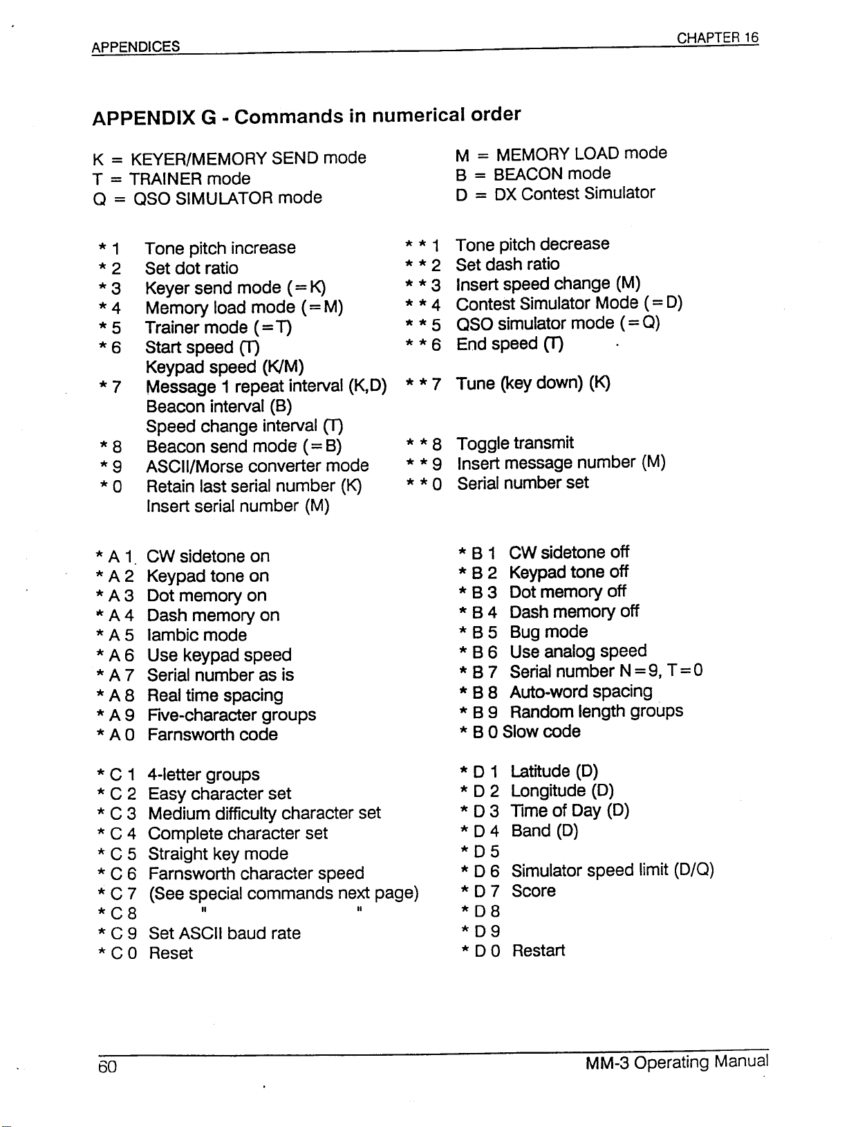
CHAPTER 16
K=KEVER/MEMORYSEND mode
T=TRAINER mode
a
=
aso SIMULATOR mode
*
*2
*3
*4
*5
*6
*8
*9
*0
*A1
*A2
*A3
•••.A4
*A5
*A6
*A7
*A8
*A9
*AO
Tone pitch increase
1
Set dot ratio
Keyer send mode
Memory load mode
Trainer mode
Start speed (T)
Keypad speed (KIM)
Message 1 repeat interval (K,D)
Beacon interval (B)
Speed change interval (T)
Beacon send mode
ASCII/Morse converter mode
Retain last serial number (K)
Insert serial number (M)
CW sidetone on
Keypad tone on
Dot memory on
Dash memory on
Iambic mode
Use keypad speed
Serial number as is
Realtime spacing
Five-character groups
Farnsworth code
(=
T)
(=
K)
(=
(=
M)
B)
M=MEMORYLOAD mode
B=BEACONmode
o
=
OX
Contest Simulator
* * 1 Tone pitch decrease
* * 2 Set dash ratio
* * 3 Insert speed change (M)
* * 4 Contest Simulator Mode(=D)
* * 5 aso simulator mode
* * 6 End speed (T)
* * 8 Toggle transmit
* * 9 Insert message number (M)
* * 0 Serial number set
*B1
*B2
*B3
*B4
*B5
*B6
*B7
*B8
* B 9 Random length groups
* B 0 Slow code
CW sidetone off
Keypadtone off
Dot memory off
Dash memory off
Bug mode
Use analog speed
Serialnumber N=9, T=0
Auto-word spacing
(=
a)
*C1 4-letter groups
*C2
*C3
*C4
*C5 Straight key mode
*C6
*C7
*C8
*C9
*CO Reset
Easy character set
Medium difficulty character set
Complete character set
Farnsworth character speed
(See special commands next page)
I'
Set ASCII baud rate
*01
*02
*03
*04
*05
*06
II
*07 Score
*08
*09
*00
Latitude (D)
Longitude (D)
Time of Day (D)
Band (D)
Simulator speed limit (0/0)
Restart
Page 62
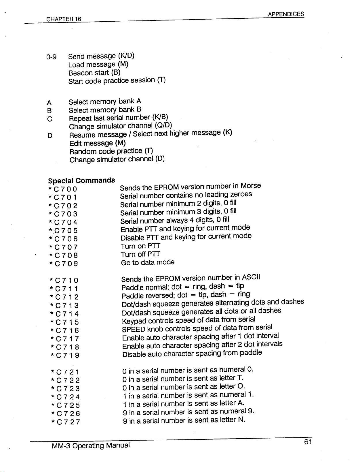
0-9 Send message (KID)
Load message (M)
Beacon start (B)
Start code practice session
A Select memory bank A
B Select memory bank B
C Repeat last serial number (KlB)
Change simulator channel (010)
o
Special Commands
*C700
*C701
*C702
*C703
*C704
*.C7 05
*C706
*C707
*C708
*C709
Resume messageISelect next higher message (K)
Edit message (M)
Random code practice
Change simulator channel (D)
Sends the EPROM version number in Morse
Serial number contains no leading zeroes
Serial number minimum 2 digits, 0 fill
Serial number minimum 3 digits, 0 fill
Serial number always 4 digits, 0 fill
Enable PIT and keying for current mode
Disable PIT and keying for current mode
Turn on PIT
Turn off PIT
Go to data mode
(T)
(T)
*C710
*C711
*C712
*C713
*C714
*C715
*C716
*C717
*C718
*C719
*C721
*C722
*C723
*C724
*C725
*C726
*C727
Sends the EPROM version number in ASCll
Paddle normal; dot
Paddle reversed; dot
Dot/dash squeeze generates alternating dots and dashes
Dot/dash squeeze generates all dots or all dashes
Keypad controls speed of data from serial
SPEED knob controls speed of data from serial
Enable auto character spacing after 1 dot interval
Enable auto character spacing after 2 dot intervals
Disable auto character spacing from paddle
o
in a serial number is sent as numeral
o
in a serial number is sent as letter T.
o
in a serial number is sent as letter O.
1 in a serial number is sent as numeral 1.
1 in a serial number is sent as letter A.
9 in a serial number is sent as numeral 9.
9 in a serial number is sent as letter N.
=
ring, dash
=
tip, dash
=
=
tip
ring
o.
Page 63
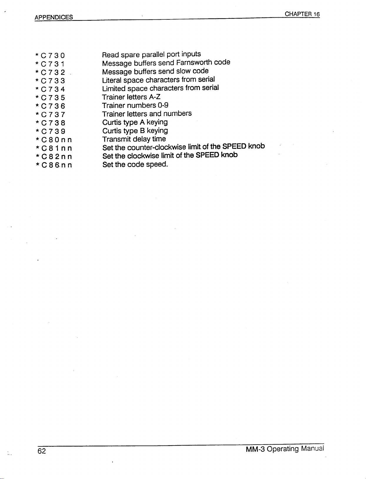
*C730
*C731
*C732
*C733
*C734
*C735
*C736
*C737
*C738
*C739
*C80nn
*C81nn
*C82nn
*C86.nn
Readspare parallel port inputs
Message buffers send Farnsworth code
Message buffers send slow code
Literal space characters from serial
Limited space characters from serial
Trainer letters A-Z
Trainer numbers 0-9
Trainer letters and numbers
Curtis type A keying
Curtis type 8 keying
Transmit delay time
Setthe counter-clockwise limit of the SPEED knob
Setthe clockwise limit of the SPEEDknob
Set the code speed.
Page 64
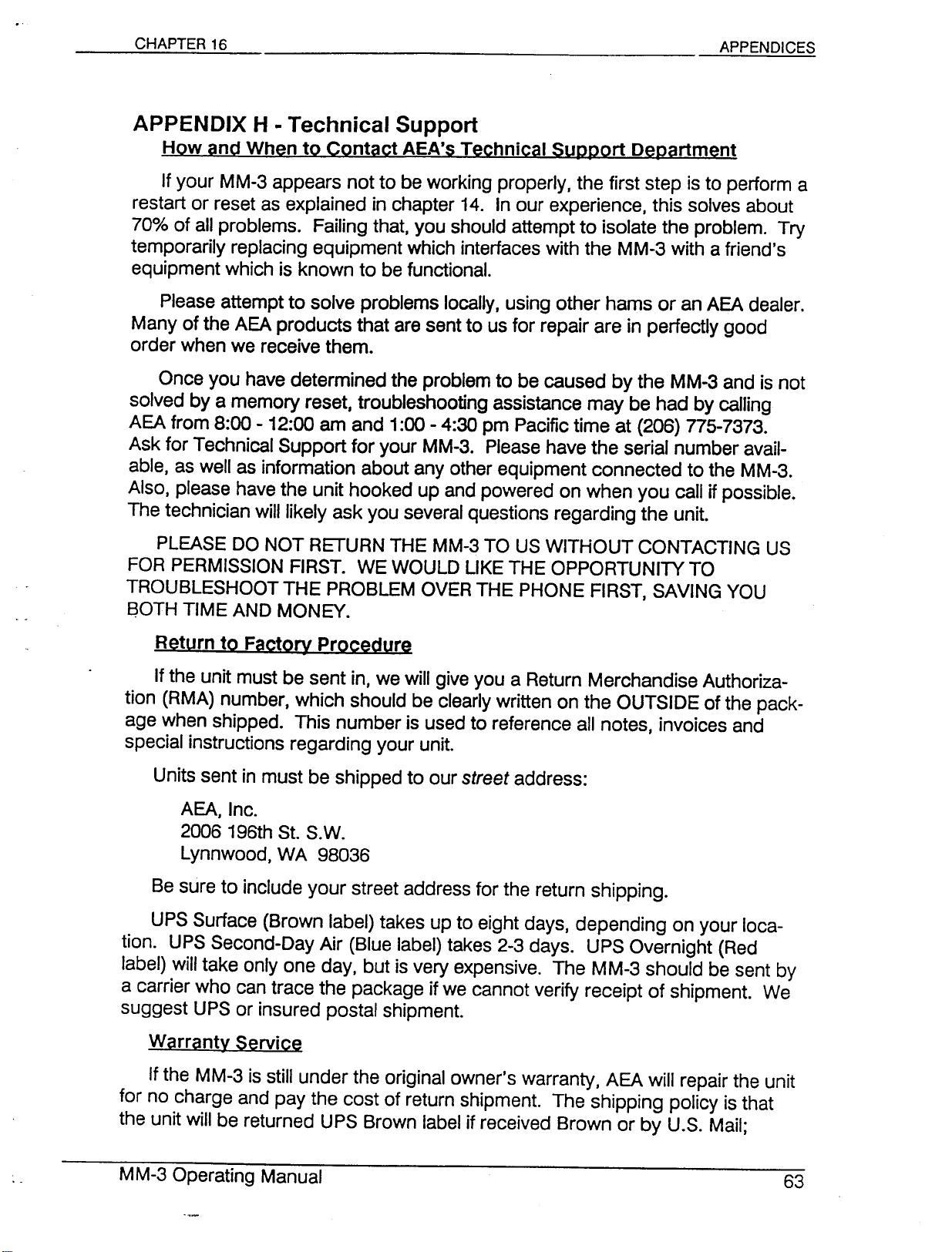
APPENDIX H • Technical Support
How and When to Contact AEA's Technical Support Department
If your MM-3 appears not to be working properly, the first step is to perform a
restart or reset as explained in chapter 14. In our experience, this solves about
70% of all problems. Failing that, you should attempt to isolate the problem. Try
temporarily replacing equipment which interfaces with the MM-3 with a friend's
equipment which is known to be functional.
Please attempt to solve problems locally, using other hams or an AEA dealer.
Many of the AEA products that are sent to us for repair are in perfectly good
order when we receive them.
Once you have determined the problem to be caused by the MM-3 and is not
solved by a memory reset. troubleshooting assistance may be had by calling
AEA from 8:00 - 12:00 am and 1:00 - 4:30 pm Pacific time at (206) 775-7373.
Ask for Technical Support for your MM-3. Please have the serial number avail-
able, as well as information about any other equipment connected to the MM-3.
Also, please have the unit hooked up and powered on when you call if possible.
The technician will likely ask you several questions regarding the unit.
PLEASE DO NOT RETURN THE MM-3 TO US WITHOUT CONTACTING US
FOR PERMISSION FIRST. WE WOULD LIKE THE OPPORTUNITY TO
TROUBLESHOOT THE PROBLEM OVER THE PHONE FIRST, SAVING YOU
aOTH TIME AND MONEY.
Return to Factory Procedure
If the unit must be sent in, we will give you a Return Merchandise Authoriza-
tion (RMA) number, which should be clearly written on the OUTSIDE of the pack-
age when shipped. This number is used to reference all notes, invoices and
special instructions regarding your unit.
Units sent in must be shipped to our
AEA, Inc.
2006 196th St. S.W.
Lynnwood,WA 98036
Be sure to include your street address for the return shipping.
UPS Surface (Brown label) takes up to eight days, depending on your loca-
tion. UPS Second-Day Air (Blue label) takes 2-3 days. UPS Overnight (Red
label) will take only one day, but is very expensive. The MM-3 should be sent by
a carrier who can trace the package if we cannot verify receipt of shipment. We
suggest UPS or insured postal shipment.
Warranty Service
If the MM-3 is still under the original owner's warranty, AEA will repair the unit
for no charge and pay the cost of return shipment. The shipping policy is that
the unit will be returned UPS Brown label if received Brown or by U.S. Mail;
street
address:
Page 65
returned Blue label if received Blue or Red or by other overnight service; or
returned as the owner states if he/she furnishes the cost for the return method
selected. A copy of the sales receipt must be included with each unit sent in for
warranty service.
The warranty is for the original owner only and cannot be transferred.
Non-Warranty Service
If the MM-3 is out of warranty. the $40 flat repair rate (subject to change
without notice or obligation) may be either charged to your Visa·or MasterCard.
paid for by personal check or money order or returned UPS COD (for an addi-
tional $2.50). The $40 flat rate includes return shipping per the above policy.
For either Warranty or Non-Warranty service. we will typically have a unit
repaired and ready for return shipping within five to 10 working days. if we~have
all the "facts. If we need to call you for some reason. it may take longer. PLEASE
include a letter stating the problem in detail and any additional information which
may help us find the problem. Also include any phone numbers where you can
be reached if necessary. AEA is not responsible for damaged caused by acts of
God. improper alterations. poor storage/handling. etc.
Page 66
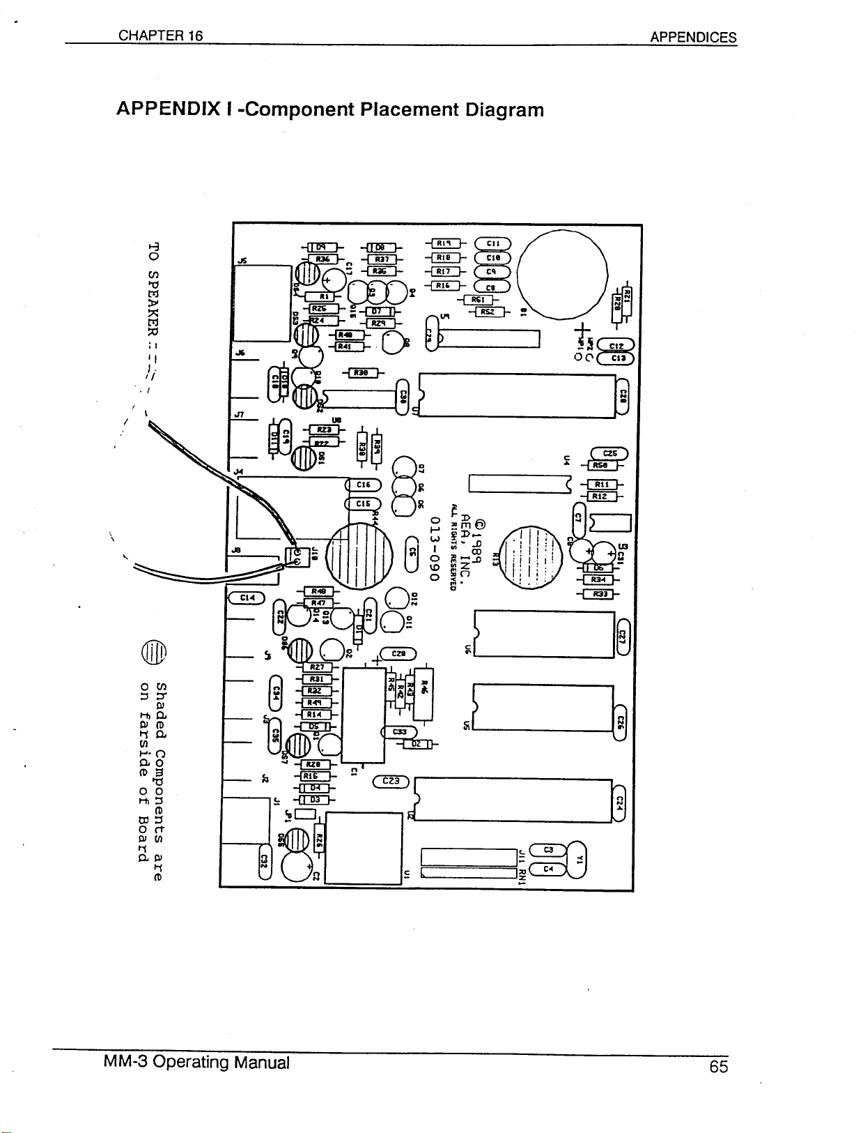
APPENDIX I -Component Placement Diagram
8
0
en
't1
ttj
~
~
ttj
::tl
;I
"
J.
II
. I
I
\
"
.n
~D
~ rTJ
6>
~D •.•.
•.•• .D
•• co
:Z.o
!:lo
;:;.
0
:;:-
~
t~
o
C'
CI3
B
.•• RS8
c~
<
-rno-
®
~
-DID-
CillD
oen
::s::r
t\l
Hlo,
t\l
ro
Ii
0.
(Jl
1-'. (")
0.0
ro
a
'0
o
0
Hl::S
ro
tIl::S
o rt
t\l (Jl
Ii
o,t\l
Ii
ro
~'@Q2
RZ7
@-rnD-
:: ~
.•. -I::!E}-
~,
.•-rno-
f;j
\~F"
~ I
::l :::
~D
@!);
)
J
I~OO
I~
l:
c~
I@
~
~
Page 67
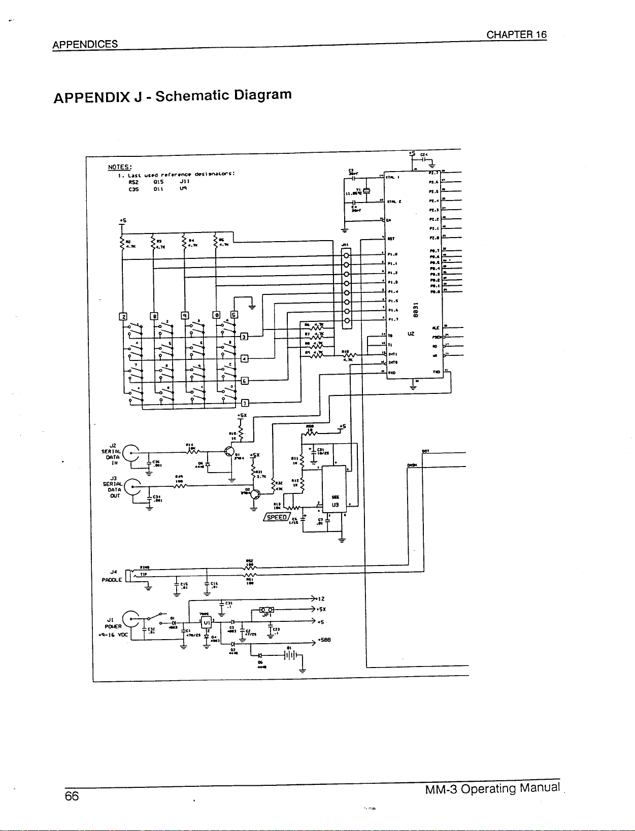
.!:!QI§.:
1. L.ast
SERIAL
•••Z
C2=I
OATA
IN CX
us.d ,..r.,..nc.
RsZ
C3S
015 •.•11
011 U'I
.oo,
c::s.si.,. .•
c.ors:
·".TIlL'
..
.
'"
.
"I.•
PI.!
PI.'
•...
"I.S
.'.6
••••f
Ie ,.
,e
U
,
,."
.
"nl
.
..•
• , ••. C
asr
PI.I
'"
•••
CD
'l<
~
....
....
....
"
....
"
.
•••r
....
"
n
....
N.'
N.I
"
M'
N.O
N.'
"
N.I
"
N.l
"
N.l
"
M
N.I
....
"
n
"
"
SE~~AL~-=
DATA
cur
•.•• n"3!L.
PAOOLE~
(34
.eo,
"NO
'I'
-=
Page 68
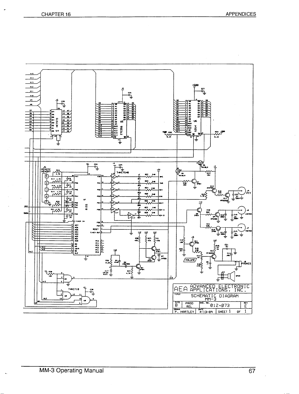
0'
DO
OS
..
0'
oz
D.
..
'.,
'
'
'
'
·oz
'
'OO
..
..
..
..
..
..
U.
..
t-
'"
an
~
..
C25
~
.,
"
••
"
..
••
"
.. ..
..
"
..
..
"
..
'"
~
.. .. ..
..
0
..
...
.,
0"
..
"
.
..
"
'I At.
'1 A.I
• AU
•• AU
" AI"-
"e!:
"
..
••
..
••
..
.,
..
...
D.
••
..
..-
....
..:
.,
~
..
..
N
U
t-
N
111:"
..
..
"
•
.
..
+Sllll
M
..
ADVANCED ELECTRONIC
APPLICATIONS, INC.
SCHEMATIC DIAGRAM
MM-3
DCl.
"'.1312-:-1373
SHEET
1
Page 69
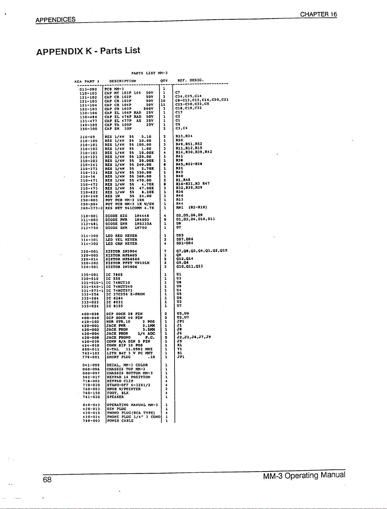
CHAPTER 16
013-090
110-103
121-102
121-103
121-104
122-103
130-106
130-416
131-477
140-105
150-300
210-05
210-100
210-101
210-102
210-103
210-121
210-203
210-241
210-H2
210-331
210-36
210-471
210-472
210-473
210-122
230-240
250-003
250-004
260--272-2
310-001
311-003
312-611
312-750
314-300
314-101
314-102
320-001
320-005
320-014
320-202
320-501
310-001
330-010
331-010-1
331-540-1
331-573-1
332-256
332-264
333-023
333-024
400-021
400-040
410-102
420-001
420-002
420-004-
420-001
420-039
424-010
650-011
762-103
779-001
041-099
060-096
060-097
502-017
nl-002
7)0-020
760-001
760-150
761-020
040-00
420-013
420-015
'20-024
769-001
PCB 1lM-3
CAP "Y 103P 10\
CAP CR 102P
CAP CR 103P
CAP CR 104P
CAP CR 103P
CAP EL 106P RAO
CAP EL 476P RAO
CAP EL 477P AX
CAP TA 105P
CAP S" lOP
RES 1/4W 5\ 5.10
RES 1/4W 5\ 10.00
RES l/CW 5\ 100.00
RES 1/4W 5\ 1.00
RES l/CW 5\ 10.00K
RES 1/4W 5\ 120.00
RES l/CW 5\ 20.00K
RES l/CW 5\ 2CO.00
RES l/CW 5\ 2.70K
RES l/CW 5\ )30.00
RES l/CW 5\ )60.00
RES l/CW 5\ C70.00
RES l/CW 5\ 4.70K
RES l/CW 5\ C7.00K
RES l/CW 5\ 1.20K
RES lW 5\ 24.00
POT PCB 1lM-) 10K
POT PCB 1lM-) 1 K W/SW
RES NET 9'lCOIlM C.7K
DIODE SIG
DIODE PWR
DIODE ZlIR
DIODE ZlIR
LEO REO KEYER
LEO YEL KEYER
LEO GRN KEYER
XISTOR 21139OC
XISTOR "PSA05
XISTOR "PS6560
XISTOR prET VlI10Ul
XlSTOR 2113906
IC 7105
IC 555
IC 74HCTI0
IC 7CHCT5CO
IC 74HCT57J
IC
27C256
IC 6264
IC 1011
IC 1155
DIP SOCK 21 PIli
DIP SOClC CO PIli
HOR STR.I0 2 POS
J AClC PWR 2 • 11lM
JACK PHOll ). 5KK
JACK PHOll l/C ADC
JAClC PHOllO P.C.
COllll RIA 0111 5 PIli
COHII SIP 10 POS
X-TAL 11.0592 KHZ
LITH BAT ) V PC KHT
SHORT PLUG .10
DECAL, 1lM-) COLOR
CHASSIS TOP 1lM-)
CHASSIS BOTTOK KH-)
KEYPAD 16 POSITION
KEYPAD CLIP
STAlIO-Orr 6-32Xl/2
1OI0B W/POINTER
rOOT, BLK
SPEAKER
OPERATING MANUAL ""-3
DIN PLUG
PHONO PLUG(RCA TYPE)
PHOHE PLUG
POWER CABLE
111CUI
111COO)
11152)51.
111750
E-PROK
1/4"
50V
50V
50V
50V
500V
25V
50V
25V
25V
1 COHO
C7
CH,CJS,C14
CI-C13,C15,C16,C20,C2l
C2)-C)O,Cn,C5
ClI, C19, cn
C17
C2
Cl
C6
C3,CC
Rn,RH
R50
R49,R51,R52
Rll, R12, R15
R14 ,R30, R)9 ,RC 2
RU
R"
RC5,R22-R2I
R11
RU
RCO
Rl,RU
R16-R21,R) RC7
R32,R)5,R29
R36
RU
JIl3
RU
RNl (R2-Rl0)
02,05,06,09
01, D), DC, 010, 011
01
07
OS5
OS7,OS6
OSl-DSC
Q7,QI,Q),QC,Ql,Q2,Q15
Q9
QU,QU
Q5,Q'
QI0,Qll,Ql)
U5,U'
U2,U7
JPl
Jl
JI
J4
J2 ,J),J',J7 ,J9
J5
Kl
VI
Bl
JPl
MM-3 Operating Manual
Page 70
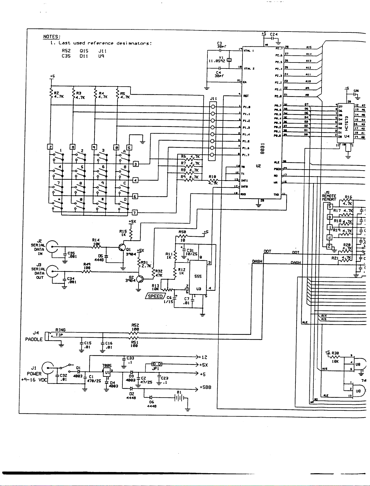
NOTES:
1.
+5
.
RZ
04.7K
[Z o~
--;~
n~
--;~
-o...J....
9--
0"""::'
-:~
used rl'fl'rence
Last
R52 OIS JII
011
C35
R3
".7K
8 'l 8
2
~~
o~
~=-
,,--!!..
~=-
"-..!.
~=-
Uq
R04
04.7K 04.7K
~~
o~
~~
o~
~~
o...!..
~~
~~
MTA
~1~C2=I
IN C3S
DATA
~1~C2=I
OUT
J4 ~
PADDLE
Jl
~Ol
POWER
voc
J
."l-16
RING
f
C32
.081
C304
.881
"ee3
.al
"""8
A04'l
lee
lCI5
.01
CI
"7a/2S
-=- -=-
desi"nators:
3
~~
"";.:...,
~--
-;--
~
I
CI6
.01
i
780S
UI
z
0"
"083
RS
-=-
5
o..e...
Il-
3
o-..!.
04
o~
6
o~
1
IK
R·L
pi
'ta
01
+~
3."
Ral
3."
Z.7K
QZ
-=-
....
!SPEEO!
RSZ
18e
RSI
10a
:!::C33
l·1
03,
J,
"a03J[CZ JeC23
"7/ZS -=-.1
'"
02
I
"""8
04""8
RPI!
10K
-
~
JPI
..
N'
06
R32
"7K
RIl'
IK
,
'V
C&
1/15
.L
~
041K
R6
R7 v~ 7K
R8 v".7K
Rqv".7K
RS8
1'0
+l
.Jl01ZS a
C31
+5
.1
~ 3
RIZ
IK
555
Z
U3
.~
1
+
c71
.01T
~6-
::. 12
)+5X
" +5
, +588
,
81
{111'1
C3
3.~~r
Yll
".e~.'lZT
"
C04
3e~r
1
:E-
'~
~
-
I~
:~
:~
..•...•
'""
-
••...
~
••...
-
RI~
~:7l:
..1...
I" XTM. I
•• ICT ••• Z
• £A
•
AIr
•••••
•••••
".oZ
•••••
"too.
....
7 ••••(
" •• 7
••
71
F:;
•Nt'l
..
INt'.
..
-
(
UZ
.,1."
DASH
r:~
/'t.'
ZlI
pt.,
17
1-2.•'5 K
".4 Z'I
z.
pt ••
/'t.z a
Izz
/'t••
pt ••
I'
1-
N.7
I••
N.'
I~
N.'
I..,
••••
I.
N ••
I.••
".1
10••
N••
I•••
•••••
..•
('I)
Cll
Cll
IlU
-
~
I'SEII
..
00
...
lOt
TIeD
l
OOT
nnT
"""'''
.IS
.,.
•••
••z
."
.,.
•••
••
ft7
D6
no: ,
••••
N
DI
D'
011
ou:
/
/
/
/
/
/
>-
REMOTE .R16
MEMORY
t-,.'
-
om
'06
7",
'rw
'01
·112
• 0'
Z
01
1I •
.15
~ 1".7K
tRI~
~RI~
~RI~
-{Z 04
t
- r'vv
RZI~
0.5
1-
~3a
10K
0.5
.ou:
.
czc
Q.
m
~
~
~
r-
'"
~
UI
...
~
U
J.!.?--!!
:I:
~
U04
Jl,L!!.
•
-=-
j:~
~~
l5=~
l5=.~
RZ
-&
~
f-Ot:
[§~
Lf.C
•
-;{u~
'g
t,
~U8
••
-
-or
74
Page 71
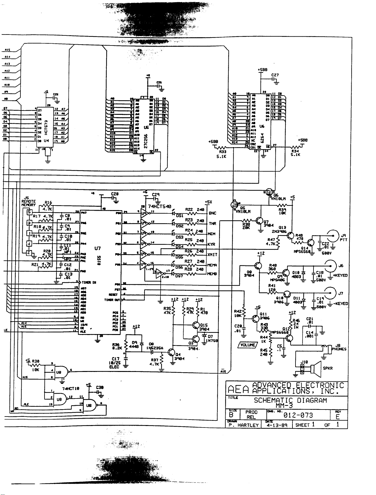
rrn ••••
:
::.
:
::.
.
"
: :; .!.L
• lS
••••
1'1
•••
•••
•••
•••
+588
T.
9
R33
5.IK
+598
--;c~
R3.••
S.IK
+5B8
.1
.)5
REMOTE .l{lp
MEMORY
r~'~
5 4.71<
RI7 4.7k
3' ~
.JRI~
I
RI~
-l
2 :~~
_ "Vvv·
R21rM
+.¥-
R3e
10k
~'
==
..J
"'""C'I
J.lill _
:!:
..J
j=.~.j'
==
-J
==
-J
•
C8
.lill "
Cllil
.01 •••
WPI
o••••
CIZ
.lill •• _
C13
.01 ~
_. IIlI
..
:
•.• III •
t.LllLE
os
-
Me
-
I'lle
-
T~I •
.,
-
-
,.
-
-
l1li
-
:...
cza
~
cn
I
lelZS
ELfC .••.
•• CZ'l
:....:j!:L
Ie
7"1HfT540
_....... I
;..
IZ
.~
,/
~:':l...
.,
;/
,~
.~
,/
,:-:....
/'"
• :':l
~"'~ n
I
"
"
U ;:.
Z••• ~
-
I
I
""="
R35
47K
ll8
U~Z3SA
,.
.
R37
".7K
'=
~OSI
:'.: RZ3
OSZ
I
"053
I
lJS4
I
~U~
I
I
056 RZS
OS7
+ Z +IZ
IP
0
'1
'"
.••.3ee ••
R22
Z40
240
RZ" t048
R25 Z••0
R~&•. 248
RZ7
Z48
248
+~Z
RZCl RI
••71<
> ••
A:)
~~~~se
3'18 .••·
70
015
3'10'"
+5X
11£19
8t«:
Tr«
HEM
KYR
XHIT
HEtt'l
Ais
~
~rllLH
-
Sjt:Q6
Nl~M
.
~07
~~ .J
3qe.. 013
.•..R4Z;~)~1~
.•••7K •
+
12 11PS656.••.
.J,
08 'CI
3•••
R3'1
18K
+5
01 .••
I
74HCTllil
~~
~ "'\ t.
~~LU8 r-;~'
+
II ~
C38
 Loading...