

Page 1

User Manual
ADAM-6000 Series
Ethernet-based Data Acquisition
and Control Modules
Page 2

Copyright
Part No. 2003600003 Edition 9
Printed in Taiwan August 2018
The documentation and the software included with this product are copyrighted 2018
by Advantech Co., Ltd. All rights are reserved. Advantech Co., Ltd. reserves the right
to make improvements in the products described in this manual at any time without
notice. No part of this manual may be reproduced, copied, translated or transmitted
in any form or by any means without the prior written permission of Advantech Co.,
Ltd. Information provided in this manual is intended to be accurate and reliable. However, Advantech Co., Ltd. assumes no responsibility for its use, nor for any infringements of the rights of third parties, which may result from its use.
Acknowledgements
Intel and Pentium are trademarks of Intel Corporation.
Microsoft Windows and MS-DOS are registered trademarks of Microsoft Corp.
All other product names or trademarks are properties of their respective owners.
Product Warranty
Advantech warrants to you, the original purchaser, that each of its products will be
free from defects in materials and workmanship for two years from the date of purchase.
This warranty does not apply to any products which have been repaired or altered by
persons other than repair personnel authorized by Advantech, or which have been
subject to misuse, abuse, accident or improper installation. Advantech assumes no
liability under the terms of this warranty as a consequence of such events.
Because of Advantech’s high quality-control standards and rigorous testing, most of
our customers never need to use our repair service. If an Advantech product is defective, it will be repaired or replaced at no charge during the warranty period. For outof-warranty repairs, you will be billed according to the cost of replacement materials,
service time and freight. Please consult your dealer for more details.
If you think you have a defective product, follow these steps:
1. Collect all the information about the problem encountered. (For example, CPU
speed, Advantech products used, other hardware and software used, etc.) Note
anything abnormal and list any onscreen messages you get when the problem
occurs.
2. Call your dealer and describe the problem. Please have your manual, product,
and any helpful information readily available.
3. If your product is diagnosed as defective, obtain an RMA (return merchandize
authorization) number from your dealer. This allows us to process your return
more quickly.
4. Carefully pack the defective product, a fully-completed Repair and Replacement
Order Card and a photocopy proof of purchase date (such as your sales receipt)
in a shippable container. A product returned without proof of the purchase date
is not eligible for warranty service.
5. Write the RMA number visibly on the outside of the package and ship it prepaid
to your dealer.
ADAM-6000 User Manual ii
Page 3

Declaration of Conformity
CE
This product has passed the CE test for environmental specifications when shielded
cables are used for external wiring. We recommend the use of shielded cables. This
kind of cable is available from Advantech. Please contact your local supplier for
ordering information.
FCC Class A
Note: This equipment has been tested and found to comply with the limits for a Class
A digital device, pursuant to part 15 of the FCC Rules. These limits are designed to
provide reasonable protection against harmful interference when the equipment is
operated in a commercial environment. This equipment generates, uses, and can
radiate radio frequency energy and, if not installed and used in accordance with the
instruction manual, may cause harmful interference to radio communications. Operation of this equipment in a residential area is likely to cause harmful interference in
which case the user will be required to correct the interference at his own expense.
Technical Support and Assistance
1. Visit the Advantech web site at www.advantech.com/support where you can find
the latest information about the product.
2. Contact your distributor, sales representative, or Advantech's customer service
center for technical support if you need additional assistance. Please have the
following information ready before you call:
– Product name and serial number
– Description of your peripheral attachments
– Description of your software (operating system, version, application software,
etc.)
– A complete description of the problem
– The exact wording of any error messages
iii ADAM-6000 User Manual
Page 4

Safety Instructions
1. Read these safety instructions carefully.
2. Keep this User Manual for later reference.
3. Disconnect this equipment from any AC outlet before cleaning. Use a damp
cloth. Do not use liquid or spray detergents for cleaning.
4. For plug-in equipment, the power outlet socket must be located near the equip-
ment and must be easily accessible.
5. Keep this equipment away from humidity.
6. Put this equipment on a reliable surface during installation. Dropping it or letting
it fall may cause damage.
7. The openings on the enclosure are for air convection. Protect the equipment
from overheating. DO NOT COVER THE OPENINGS.
8. Make sure the voltage of the power source is correct before connecting the
equipment to the power outlet.
9. Position the power cord so that people cannot step on it. Do not place anything
over the power cord.
10. All cautions and warnings on the equipment should be noted.
11. If the equipment is not used for a long time, disconnect it from the power source
to avoid damage by transient overvoltage.
12. Never pour any liquid into an opening. This may cause fire or electrical shock.
13. Never open the equipment. For safety reasons, the equipment should be
opened only by qualified service personnel.
14. If one of the following situations arises, get the equipment checked by service
personnel:
The power cord or plug is damaged.
Liquid has penetrated into the equipment.
The equipment has been exposed to moisture.
The equipment does not work well, or you cannot get it to work according to the
user's manual.
The equipment has been dropped and damaged.
The equipment has obvious signs of breakage.
15. DO NOT LEAVE THIS EQUIPMENT IN AN ENVIRONMENT WHERE THE
STORAGE TEMPERATURE MAY GO BELOW -20° C (-4° F) OR ABOVE 60° C
(140° F). THIS COULD DAMAGE THE EQUIPMENT. THE EQUIPMENT
SHOULD BE IN A CONTROLLED ENVIRONMENT.
16. CAUTION: DANGER OF EXPLOSION IF BATTERY IS INCORRECTLY
REPLACED. REPLACE ONLY WITH THE SAME OR EQUIVALENT TYPE
RECOMMENDED BY THE MANUFACTURER, DISCARD USED BATTERIES
ACCORDING TO THE MANUFACTURER'S INSTRUCTIONS.
17. The sound pressure level at the operator's position according to IEC 704-1:1982
is no more than 70 dB (A).
DISCLAIMER: This set of instructions is given according to IEC 704-1. Advantech
disclaims all responsibility for the accuracy of any statements contained herein.
ADAM-6000 User Manual iv
Page 5

Contents
Chapter 1 Understanding Your System ..............1
1.1 Introduction ............................................................................................... 2
Figure 1.1 ADAM-6000 Module System Architecture .................. 2
1.2 Major Features .......................................................................................... 2
1.3 Specifications ............................................................................................ 4
1.4 Dimensions ............................................................................................... 4
Figure 1.2 ADAM-6000 Module Dimensions ............................... 4
1.5 LED Status ................................................................................................ 5
Chapter 2 Hardware Selection Guidelines..........7
2.1 Selecting an I/O Module............................................................................ 8
Table 2.1: I/O Selection Guidelines............................................. 8
2.2 Selecting a Link Terminal and Cable ........................................................ 8
Figure 2.1 Connecting ADAM-6000 Modules to an Ethernet Ter-
minal via Cable ........................................................... 9
Table 2.2: Ethernet RJ-45 Port Pin Assignment Chart................ 9
2.3 Selecting an Operator Interface ................................................................ 9
Chapter 3 Hardware Installation Guide .............11
3.1 Interface Introduction .............................................................................. 12
3.2 Mounting Options .................................................................................... 13
3.2.1 Panel Mounting ........................................................................... 13
Figure 3.1 Panel Mounting Bracket Dimensions........................ 13
Figure 3.2 How to Fix a Module on the Mounting Bracket......... 13
3.2.2 DIN Rail Mounting....................................................................... 14
Figure 3.3 How to Fix a Module on the DIN Rail Adapter.......... 14
Figure 3.4 How to Secure a Module to a DIN Rail..................... 14
3.3 Wiring and Connections .......................................................................... 15
3.3.1 Power Supply Wiring................................................................... 15
Figure 3.5 How to Connect the Module Power Wires................ 15
3.3.2 I/O Module Wiring ....................................................................... 15
Chapter 4 Introduction to Analog ADAM-6000 I/O
Modules17
4.1 Analog Input Modules ............................................................................. 18
4.2 ADAM-6015 7-ch Isolated RTD Input Module ......................................... 18
4.2.1 Specifications.............................................................................. 18
4.2.2 Application Wiring ....................................................................... 20
Figure 4.1 ADAM-6015 RTD Input Wiring ................................. 20
4.2.3 Address Assignment ................................................................... 20
4.3 ADAM-6017 8-ch Analog Input/2-ch Digital Output Module.................... 20
4.3.1 Specifications.............................................................................. 20
Figure 4.2 ADAM-6017 Jumper Switches.................................. 22
4.3.2 Application Wiring ....................................................................... 23
Figure 4.3 ADAM-6017 Analog Input Wiring............................. 23
Figure 4.4 ADAM-6017 Analog Input Type Setting.................... 23
Figure 4.5 ADAM-6017 Digital Output Wiring ............................ 23
4.3.3 Address Assignment ................................................................... 24
v ADAM-6000 User Manual
Page 6

4.4 ADAM-6018 Isolated Thermocouple Input/8-ch Digital Output Module .. 24
Figure 4.6 ADAM-6018 8-ch Thermocouple Input..................... 24
4.4.1 Specifications.............................................................................. 24
4.4.2 Application Wiring ....................................................................... 26
Figure 4.7 ADAM-6018 Thermocouple Input Wiring.................. 26
Figure 4.8 ADAM-6018 Digital Output Wiring............................ 26
4.4.3 Address Assignment................................................................... 26
4.5 ADAM-6024 12-ch Isolated Universal I/O Module .................................. 26
4.5.1 Specifications.............................................................................. 27
Figure 4.9 ADAM-6024 Jumper Settings................................... 28
4.5.2 Application Wiring ....................................................................... 29
Figure 4.10ADAM-6024 Analog I/O Wiring................................. 29
Figure 4.11ADAM-6024 Digital Input Wiring............................... 29
Figure 4.12ADAM-6024 Digital Output Wiring ............................ 30
4.5.3 Address Assignment................................................................... 30
Chapter 5 Introduction to Digital ADAM-6000 I/O
Modules31
5.1 Digital I/O and Relay Modules ................................................................ 32
5.2 ADAM-6050 18-ch Isolated Digital I/O Module ....................................... 32
5.2.1 Specifications.............................................................................. 32
5.2.2 Application Wiring ....................................................................... 33
Figure 5.1 ADAM-6050 Digital Input Wiring............................... 33
Figure 5.2 ADAM-6050 Digital Output Wiring............................ 33
5.2.3 Address Assignment................................................................... 34
5.3 ADAM-6051 14-ch Isolated Digital I/O Module w/2-ch Counter .............. 34
5.3.1 Specifications.............................................................................. 34
5.3.2 Application Wiring ....................................................................... 35
Figure 5.3 ADAM-6051 Digital Input Wiring............................... 35
Figure 5.4 ADAM-6051 Counter (Frequency) Input................... 35
Figure 5.5 ADAM-6051 Digital Output Wiring............................ 36
5.3.3 Address Assignment................................................................... 36
5.4 ADAM-6052 16-ch Source-Type Isolated Digital I/O Module.................. 36
5.4.1 Specifications.............................................................................. 36
Figure 5.6 ADAM-6052 Jumper Settings................................... 37
5.4.2 Application Wiring ....................................................................... 38
Figure 5.7 ADAM-6052 Digital Input Wiring............................... 38
Figure 5.8 ADAM-6052 Digital Output Wiring............................ 39
5.4.3 Address Assignment................................................................... 39
5.5 ADAM-6060 6-ch Digital Input/6-ch Relay Module ................................. 39
5.5.1 Specifications.............................................................................. 39
5.5.2 Application Wiring ....................................................................... 41
Figure 5.9 ADAM-6060 Digital Input Wiring............................... 41
Figure 5.10ADAM-6060 Relay Output Wiring............................. 41
5.5.3 Address Assignment................................................................... 41
5.6 ADAM-6066 6-ch Digital Input/6-ch Power Relay Module ...................... 42
5.6.1 Specifications:............................................................................. 42
5.6.2 Application Wiring ....................................................................... 43
Figure 5.11ADAM-6066 Digital Input Wiring............................... 43
Figure 5.12ADAM-6066 Relay Output Wiring............................. 43
5.7 Digital Output Diagnostic Function.......................................................... 44
5.7.1 How to Obtain the Digital Output Diagnostic Status ................... 45
Figure 5.13Abnormal DO Diagnostic Status............................... 45
Figure 5.14Normal DO Diagnostic Status .................................. 46
Chapter 6 System Configuration Guide ........... 49
ADAM-6000 User Manual vi
Page 7

6.1 System Requirements............................................................................. 50
6.2 Installing Adam/Apax .NET Utility ........................................................... 50
6.3 Adam/Apax .NET Utility Overview........................................................... 50
Figure 6.1 Adam/Apax .NET Utility Operation Window ............. 51
6.3.1 Menu Bar .................................................................................... 51
6.3.2 Toolbar........................................................................................ 52
Figure 6.2 Adam/Apax .NET Utility Toolbar............................... 52
6.3.3 Module Tree Display Area .......................................................... 53
Figure 6.3 Adam/Apax .NET Utility Module Display Area.......... 53
6.3.4 Status Display Area .................................................................... 53
6.3.5 Configuration of ADAM-6000 Modules ....................................... 53
Figure 6.4 Adam/Apax .NET Utility - Searching for Devices...... 54
6.3.6 Group Configuration.................................................................... 62
6.3.7 I/O Configuration......................................................................... 64
Figure 6.5 All-Channel, Individual Channel, and GCL Configura-
tion Controls ............................................................. 64
6.4 Analog Input Modules (ADAM-6015, ADAM-6017, and ADAM-6018) .... 65
6.4.1 All-Channel Configuration ........................................................... 65
Figure 6.6 Channels Range Configuration Area........................ 65
Figure 6.7 Analog Input Trend Log ........................................... 68
6.4.2 Individual Channel Configuration ................................................ 70
Figure 6.8 Analog Input Alarm Mode Configuration................... 70
6.5 Universal I/O Modules (ADAM-6024)...................................................... 71
6.5.1 All-Channel Configuration ........................................................... 71
Figure 6.9 ADAM-6015 Channel Configuration ......................... 72
Figure 6.10ADAM-6024 Output Tab........................................... 72
6.6 Universal Digital I/O Modules (ADAM-6050, ADAM-6051- ADAM-6052,
ADAM-6060, ADAM-6066)...................................................................... 73
6.6.1 All-Channel Configuration ........................................................... 73
6.6.2 Individual Channel Configuration ................................................ 74
Figure 6.11Digital Input Modes ................................................... 75
Figure 6.12Digital Output Modes ................................................ 78
Figure 6.13Graph Explaining Low to High Delay Output Mode .. 80
Figure 6.14Graph Explaining Low to High Delay Output Mode .. 81
6.7 Introduction to P2P Functions ................................................................. 81
6.7.1 P2P Communication Modes ....................................................... 82
Figure 6.15Basic Mode for P2P.................................................. 82
Figure 6.16Advanced mode for P2P........................................... 83
6.7.2 P2P Communication Methods .................................................... 83
6.7.3 P2P Event Triggers..................................................................... 83
6.8 How to Configure P2P Functions ............................................................ 84
Figure 6.17Peer to Peer/Event Tab ............................................ 84
6.8.1 Basic Mode Configuration........................................................... 85
Figure 6.18P2P Basic Mode Configuration................................. 85
6.8.2 Advanced Mode Configuration.................................................... 86
Figure 6.19P2P Advanced Mode Configuration ......................... 86
Figure 6.20Copy One Setting to Other Channels....................... 87
6.9 ADAM-6000 Web Server......................................................................... 87
6.9.1 HTML 5 ....................................................................................... 88
6.9.2 Java Applet Customization ......................................................... 90
Figure 6.21Structure of the ADAM6060.jar file........................... 93
Figure 6.22Firmware Upgrade .................................................... 93
Chapter 7 Planning Your Application Program....
101
7.1 Introduction ........................................................................................... 102
7.2 ADAM .NET Class Library..................................................................... 102
Figure 7.1 Modifying ADAM-6050 .NET .................................. 103
vii ADAM-6000 User Manual
Page 8

Figure 7.2 Execute the sample code and configure your ADAM
module.................................................................... 103
7.3 Modbus Protocol for ADAM-6000 Modules........................................... 104
7.3.1 Modbus Protocol Structure ....................................................... 104
7.3.2 Modbus Function Code Introductions ....................................... 104
7.4 ASCII Commands for ADAM-6000 Modules......................................... 109
7.4.1 ASCII Syntax ............................................................................ 109
7.4.2 System Command Set.............................................................. 109
7.4.3 Analog Input Command Set...................................................... 113
7.4.4 Analog Input Alarm Command Set ........................................... 124
7.4.5 Universal I/O Command Set ..................................................... 129
7.4.6 Digital I/O Command Set.......................................................... 135
7.5 SNMP for ADAM-6000 Modules ........................................................... 138
7.5.1 ADAM MIB file .......................................................................... 138
7.5.2 SNMP Trap Configuration......................................................... 138
Figure 7.3 Trap Configuration Using Adam/Apax .NET Utility. 139
7.5.3 SNMP OID Value...................................................................... 140
7.6 MQTT for ADAM-6000 modules ........................................................... 141
7.6.1 Introduction of MQTT................................................................ 141
7.6.2 MQTT Format for ADAM module.............................................. 141
7.6.3 MQTT Configuration ................................................................. 144
7.6.4 How to Start MQTT with ADAM-6000 Modules ........................ 147
7.6.5 Real-Time Clock ....................................................................... 149
7.6.6 SNTP Configuration Using Adam/Apax .NET Utility ................. 149
7.6.7 SNTP Configuration Using ASCII Commands.......................... 150
Chapter 8 Graphic Condition Logic (GCL) ..... 151
8.1 Overview ............................................................................................... 152
8.2 GCL Configuration Environment ........................................................... 152
Figure 8.1 GCL Configuration Environment ............................ 153
Figure 8.2 Four Stages for One Logic Rule............................. 154
8.3 Configuring the Four Stages of a Logic Rule ........................................ 155
8.3.1 Input Condition Stage ............................................................... 155
Figure 8.3 Input Condition Stage Configuration ...................... 156
Figure 8.4 Scaling Function of Analog Input Mode.................. 156
Figure 8.5 Engineer Unit and Current Value ........................... 157
8.3.2 Logic Stage............................................................................... 159
Figure 8.6 Logic Stage Configuration ...................................... 159
8.3.3 Execution Stage........................................................................ 160
Figure 8.7 Execution Stage Configuration............................... 161
Figure 8.8 Send to Next Rule Function ................................... 162
Figure 8.9 The Next Logic Rule............................................... 162
8.3.4 Output Stage............................................................................. 163
Figure 8.10Output Stage Configuration .................................... 163
Figure 8.11Remote Message Output ....................................... 166
8.4 Internal Flag for Logic Cascade and Feedback .................................... 168
8.4.1 Logic Cascade .......................................................................... 168
Figure 8.12Local Logic Cascade Architecture .......................... 168
Figure 8.13Configuration of Logic Rule 1 ................................. 168
Figure 8.14Configuration of Logic Rule 2 ................................. 169
Figure 8.15Configuration of Logic Rule 3 ................................. 169
Figure 8.16Distributed Logic Cascade ..................................... 170
Figure 8.17Configuration of Logic Rule 1 ................................. 170
Figure 8.18Configuration of Logic Rule 2 ................................. 170
Figure 8.19Configuration of Logic Rule 3 ................................. 170
8.4.2 Feedback.................................................................................. 171
Figure 8.20Building Logic Feedback ........................................ 171
8.5 Logic Download and Online Monitoring ................................................ 171
ADAM-6000 User Manual viii
Page 9

Figure 8.21Online Monitoring Function..................................... 172
Figure 8.22GCL Execution Sequence ...................................... 173
8.6 Typical Applications with GCL............................................................... 173
Figure 8.23Ladder Diagram for On/Off Control ........................ 174
Figure 8.24GCL Logic for On/Off Control ................................. 174
Figure 8.25Time Chart for Sequence Control ........................... 175
Figure 8.26GCL Logic for Sequence Control (Turns On in Se-
quence and Remains On)....................................... 175
Figure 8.27Time Chart for 12 Digital Inputs to 1 Digital Output 176
Figure 8.28GCL Logic for 12 Digital Inputs to 1 Digital Output. 176
Figure 8.29Time Chart for Flicker Applications......................... 177
Figure 8.30GCL Logic for Flicker .............................................. 177
Figure 8.31Time Chart for Rising Edge .................................... 177
Figure 8.32Ladder Diagram for Rising Edge ............................ 178
Figure 8.33GCL Logic for Rising Edge ..................................... 178
Figure 8.34Time Chart for Falling Edge.................................... 179
Figure 8.35Ladder Diagram for Falling Edge............................ 179
Figure 8.36GCL Logic for Falling Edge .................................... 179
Figure 8.37Time Chart for Sequence Control (Continuously Turn
On and Off in Sequence)........................................ 180
Figure 8.38GCL Logic for Sequence Control (Continuously Turn
On and Off in Sequence)........................................ 180
Figure 8.39GCL Logic for Event Trigger (Only Occurs Once) .. 181
Figure 8.40Event Trigger Configuration (Only Occurs Once)... 181
Appendix A Design Worksheets .........................183
Appendix B Data Formats and I/O Ranges ........187
B.1 ADAM-6000 Command Data Formats .................................................. 188
Figure B.1 Request Comment Structure .................................. 188
Figure B.2 Response Comment Structure ............................... 188
B.2 ADAM-6000 I/O Modbus Mapping Tables ............................................ 193
Appendix C Grounding Reference......................223
C.1 Field Grounding and Shielding Application ........................................... 224
C.1.1 Overview ................................................................................... 224
C.2 Grounding ............................................................................................. 224
C.2.1 The Earth as a Reference......................................................... 224
Figure C.1 Thinking of the Earth as a Ground.......................... 224
C.2.2 Frame Grounds and Grounding Bars........................................ 225
Figure C.2 Grounding Bar ........................................................ 225
Figure C.3 Figure C.3: Normal and Common Mode................. 225
C.2.3 Normal Mode and Common Mode............................................ 225
Figure C.4 Normal and Common Mode ................................... 226
C.2.4 Wire impedance ........................................................................ 226
Figure C.5 High Voltage Transmission.................................... 226
Figure C.6 Wire Impedance ..................................................... 227
C.2.5 Single-Point Grounding............................................................. 227
Figure C.7 Single-Point Grounding .......................................... 227
Figure C.8 Single point grounding ............................................ 227
C.3 Shielding ............................................................................................... 228
C.3.1 Cable Shield.............................................................................. 228
Figure C.9 Single Isolation Cable ............................................. 228
Figure C.10Double Isolation Cable ........................................... 228
C.3.2 System Shielding ...................................................................... 229
ix ADAM-6000 User Manual
Page 10

Figure C.11System Shielding ................................................... 229
Figure C.12The Characteristics of the Cable............................ 229
Figure C.13System Shielding (1).............................................. 230
Figure C.14System Shielding (2).............................................. 230
C.4 Noise Reduction Techniques ................................................................ 230
Figure C.15Noise Reduction Techniques ................................. 231
C.5 Checklist ............................................................................................... 231
Appendix D REST for ADAM-6000...................... 233
D.1 REST Introduction................................................................................. 234
D.2 REST Resources for ADAM.................................................................. 234
D.2.1 Analoginput............................................................................... 234
D.2.2 Analogoutput............................................................................. 235
D.2.3 Digitalinput ................................................................................ 236
D.2.4 Digitaloutput.............................................................................. 237
D.2.5 Counter ..................................................................................... 238
ADAM-6000 User Manual x
Page 11

xi ADAM-6000 User Manual
Page 12

ADAM-6000 User Manual xii
Page 13

Chapter 1
1 Understanding Your
System
Page 14
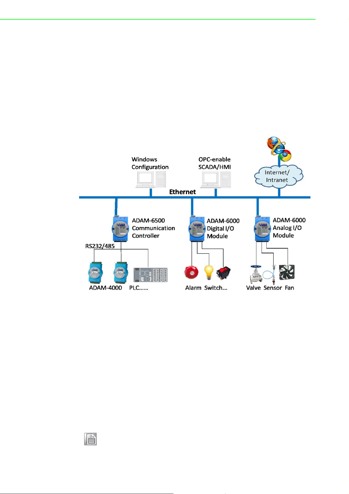
1.1 Introduction
ADAM-6000 series Ethernet-based data acquisition and control (DA&C) modules
provide I/O, data acquisition, and networking capabilities in one module, allowing you
to build a cost-effective distributed monitoring and control solution for a wide variety
of applications. Through a standard Ethernet network, ADAM-6000 modules can
retrieve I/O values from sensors and can publish them as real-time I/O values to networking nodes via LAN, intranet, or the Internet. With Ethernet-enabled technology,
ADAM-6000 modules allow you to build up a cost-effective DA&C system for building
automation, environmental monitoring, facility management, and e-manufacturing
applications. Figure 1-1 gives a brief overview of a system architecture that can be
adopted for ADAM-6000 modules.
Figure 1.1 ADAM-6000 Module System Architecture
1.2 Major Features
Ethernet-Enabled DA&C I/O Modules
ADAM-6000 modules are based on the widely utilized Ethernet networking standard,
which is employed in most business environments. You can easily add ADAM-6000
series I/O modules to existing Ethernet networks or use them in new Ethernetenabled e-manufacturing networks. This series of modules supports 10/100 Mbps
Ethernet and Modbus/TCP over TCP/IP for data connectivity, and UDP over Ethernet. With UDP/IP, ADAM-6000 series I/O modules can actively transmit data streams
to up to eight Ethernet nodes. Through Ethernet networking, HMI/SCADA systems,
and controllers, you can access and acquire real-time data from ADAM-6000 Ethernet-enabled DA&C modules. The data can then be integrated with business systems
to derive valuable business information.
Note! Some intelligent functions are only provided with the ADAM-6000-CE
version. See Appendix F for further details.
ADAM-6000 User Manual 2
Page 15

Intelligent I/O Modules
Upgraded from traditional I/O modules, all ADAM-6000 series modules have pre-built
intelligent functions that can enhance system capabilities. For example, the digital
input modules provide counter and totalizer functions; the digital output modules provide pulse output and delay output functions; the analog input modules provide
descriptive statistical data calculations (e.g., min., max., and mean); and the analog
output modules provide a PID loop control function.
Mixed I/O for All Applications
The ADAM-6000 series' mixed I/O design provides a cost-effective I/O option for
application systems. The most commonly used I/O types for single-function units are
available in a single module. This design concept not only saves I/O usage as well as
costs, but it also speeds up I/O operations. For small DA&C system or standalone
control units in medium-large systems, the ADAM-6000 series' mixed I/O design can
easily fit your application needs with only one or two modules. With additional
embedded control modules, these modules can be used to easily create a localized,
less complex, and more distributed I/O architecture.
Remote Monitoring and Diagnosis
Previous differences in communication modes and data formats made it difficult to
implement automation control and monitoring in IT-based infrastructure. In particular,
users had to convert data to transform I/O datastreams from SCADA systems before
transfer to a database or IT management system.
ADAM-6000 modules integrate the latest web language (HTML 5) and web-based
architectural style (REST) with basic authentication for users to remotely acquire I/O
data in any smart device web service without routing from the SCADA system. As an
example, a smartphone web browser can now be used to remotely access an I/O
module via HTTP.
Each ADAM-6000 module features a pre-built I/O module web page for displaying
real-time I/O data, alarms, and module status via LAN or the Internet. Using any popular Internet browser, you can perform monitoring from both local and remote sites.
Furthermore, web-enabled monitoring can be completed immediately without requiring any programming.
Chapter 1 Understanding Your System
Modbus/TCP Protocol
ADAM-6000 modules support the widely used industry standard Modbus/TCP protocol, enabling you to connect with any Ethernet controllers or HMI/SCADA software
that supports Modbus/TCP. Advantech also provides an OPC server for Modbus/TCP
so that ADAM-6000 I/O module datastreams can be integrated with OPC clientenabled software, thus freeing you from having to develop new drivers.
Customized Web Page
Since ADAM-6000 modules have a default built-in web page, you can monitor and
control the I/O status from any location by using Internet Explorer. Moreover, customized web pages can be uploaded to ADAM-6000 modules for individual applications.
Advantech provides sample code in JavaScript* as a reference for you to design your
own operator interface and then upload it to the specific ADAM-6000 modules via
Adam/Apax .NET Utility.
Modbus/TCP Software Support
The firmware for ADAM-6000 modules has a built-in Modbus/TCP server. Advantech
provides the ADAM .NET Class Library and Adam/Apax .NET Utility for module con-
3 ADAM-6000 User Manual
Page 16
figuration and customization. You can configure ADAM modules using this utility, and
it can be integrated with any human-machine (HMI) software that supports Modbus/
TCP. You can also purchase Advantech OPC Server to configure the Modbus/TCP
settings.
1.3 Specifications
Ethernet 10/100BASE-T
Wiring UTP (Cat 5 or later)
Bus Connection RJ45 modular jack
Comm. Protocol Modbus/TCP on TCP/IP and UDP
Data Transfer Rate
Status Indicator
Case PC with captive mounting hardware
Screw Terminal Block Accepts wire size #14-28 AWG, stripped length: 6.5 mm
Note! Although the equipment is designed to operate below 30% humidity,
static electricity problems are more common at lower humidity levels.
Ensure you take adequate precautions when handling the equipment.
We recommend using grounding straps, anti-static floor coverings, and
other protection measures if you use the equipment in low-humidity
environments.
Up to 100 Mbps
Unregulated 10 to 30
Power, CPU, Communication
(Link, Collide, 10/100 Mbps, Tx, Rx)
V
DC
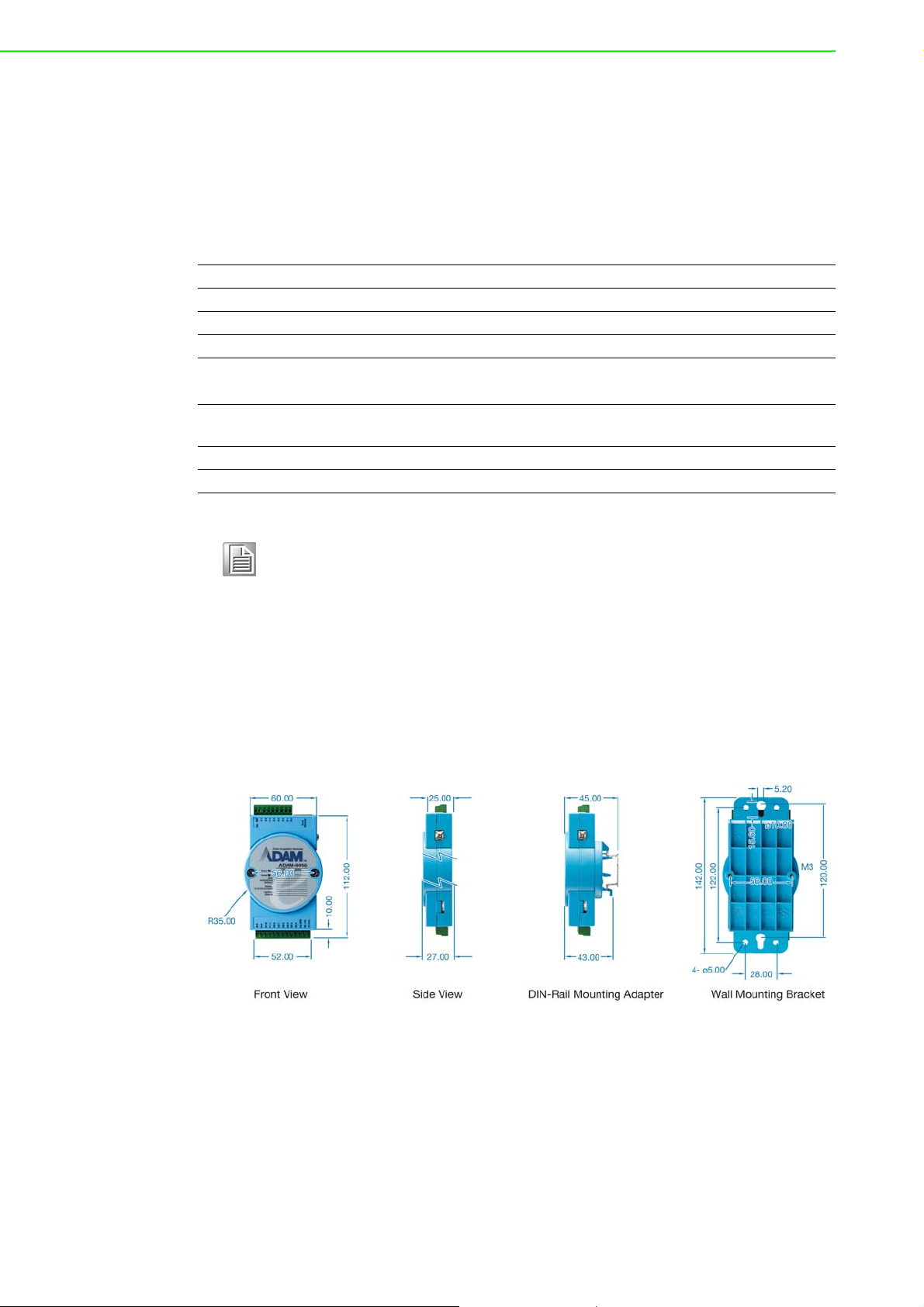
1.4 Dimensions
The following dimensions are given in millimeters. These dimensions are common for
all ADAM-6000 modules.
Figure 1.2 ADAM-6000 Module Dimensions
ADAM-6000 User Manual 4
Page 17
1.5 LED Status
There are two LEDs on the front panel of ADAM-6000 modules. Each LED has two
indicators to represent system status:
Chapter 1 Understanding Your System
LED Color Indication Behavior
Blink Module is normally running
Status
Link Green ON Ethernet is connected
Speed
COM Green Blink
Orange (when Status and
Link are on at the same time)
Orange (when speed and
COM are on at the same
time)
Red
Red ON Ethernet speed is 100 Mbps
ON for 30s
When user enable LOCATE
function
Module is transmitting or
receiving data
5 ADAM-6000 User Manual
Page 18
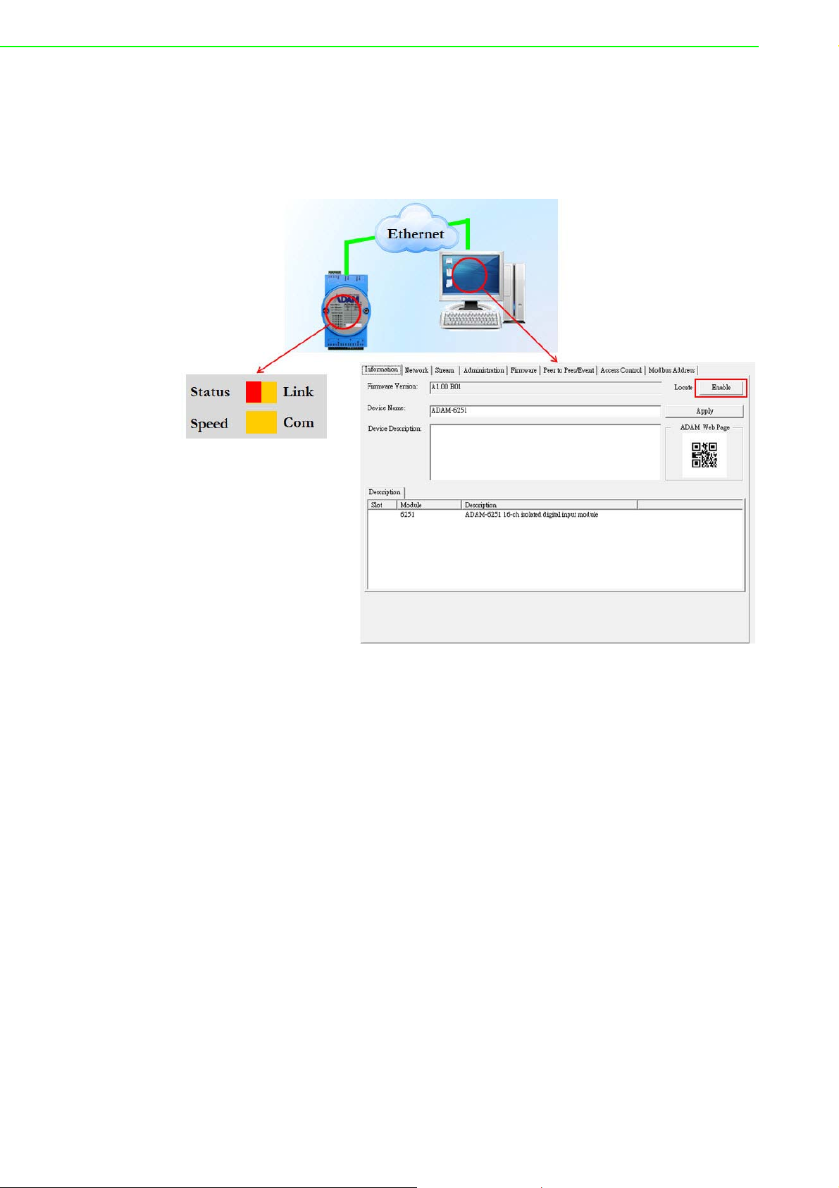
How to Locate Your Module
ADAM-6000 modules also have a locate function to help you physically identify a
specific module that you may be looking for. When this function is enabled, the Status
LED will remain red for 30 s. In Adam/Apax .NET Utility, you can enable the locate
function by clicking Enable in the Information tab.
ADAM-6000 User Manual 6
Page 19

Chapter 2
2 Hardware Selection
Guidelines
Page 20

2.1 Selecting an I/O Module
To organize an ADAM-6000 remote DA&C system, you will need to select I/O modules to act as an interface between the host PC and field devices or sensors. The following should be considered when deciding which I/O modules to select.
What types of I/O signals does your system use?
How many inputs and outputs does your system require?
How many modules are required for distributed I/O point arrangement?
How will you arrange the modules to handle I/O points in individual areas of the
installation site?
How many hubs will you require to connect all of the modules?
What is the required voltage range for each I/O module?
What isolation environment is required for each I/O module?
What are the noise and distance limitations for each I/O module?
Examples of I/O module selection considerations are detailed in Table 2.1.
Table 2.1: I/O Selection Guidelines
Type of I/O
Module
Discrete input
module and
block I/O
module
Discrete output
module and
block I/O
module
Analog input
module
Analog output
module
Example Operations Explanation
Selector switches, push buttons, photoelectric eyes, limit switches, circuit breakers,
proximity switches, level switches, motor
starter contacts, relay contacts, and thumbwheel switches
Alarms, control relays, fans, lights, horns,
valves, motor starters, and solenoids
Thermocouple signals, RTD signals, temperature transducers, pressure transducers,
load cell transducers, humidity transducers,
flow transducers, potentiometers.
Analog valves, actuators, chart recorders,
electric motor drives, analog meters
Input modules sense ON/OFF
or OPENED/CLOSED signals
Output module signals interface with ON/OFF or
OPENED/CLOSED devices
Convert continuous analog
signals into input values for a
host device
Set a host device’s output to
analog signals (generally
through transducers) for field
devices
2.2 Selecting a Link Terminal and Cable
Use an RJ-45 connector to connect the Ethernet port of ADAM-6000 modules to a
hub. The cable employed for the connection should be a Cat 3 (10 Mbps) or Cat 5
(100 Mbps) UTP/STP cable, both of which comply with EIA/TIA 586 specifications.
The maximum length between a hub and any ADAM-6000 module is 100 m (approx.
330 ft).
ADAM-6000 User Manual 8
Page 21
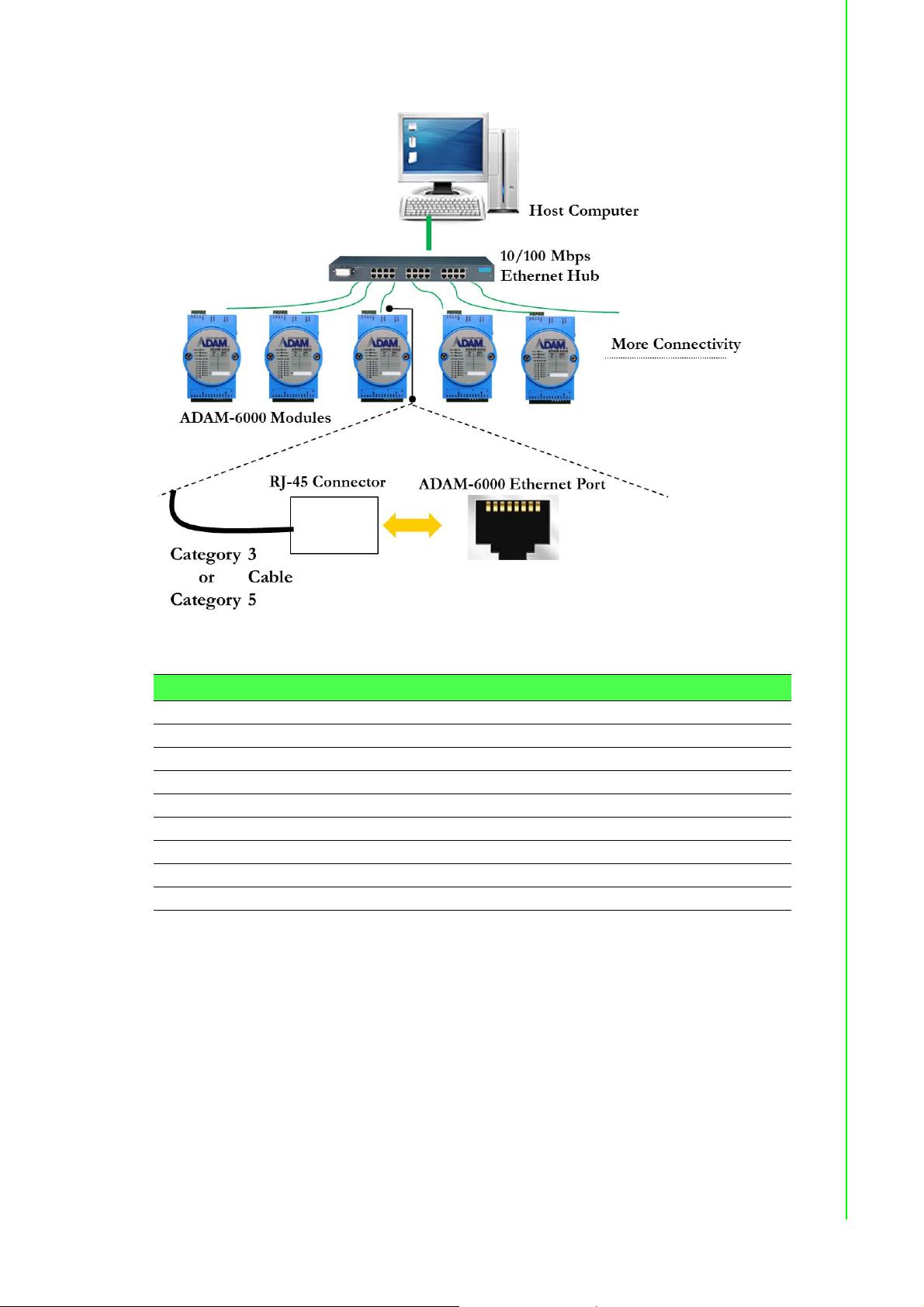
Chapter 2 Hardware Selection Guidelines
Figure 2.1 Connecting ADAM-6000 Modules to an Ethernet Terminal via Cable
Table 2.2: Ethernet RJ-45 Port Pin Assignment Chart
PIN Number Signal Function
1 RD+ Receive (+)
2 RD- Receive (-)
3 TD+ Transmit (+)
4 (Not used) 5 (Not used) 6 TD- Transmit (-)
7 (Not used) 8 (Not used) -
2.3 Selecting an Operator Interface
To complete your DA&C system, it is necessary to select an operator interface. Supporting the Modbus/TCP protocol, ADAM-6000 modules can easily be integrated into
different systems for various applications.
The real-time status of ADAM-6000 modules can be read from a web page using the
following browsers:
Microsoft Internet Explorer (version 9 or later)
Google Chrome (version 30 or later)
Safari (version 6 or later)
Mozilla Firefox (version 25 or later)
9 ADAM-6000 User Manual
Page 22

If you want to integrate ADAM-6000 modules with HMI software in a SCADA system,
HMI software packages that support Modbus/TCP can be used. Examples are as follows:
Advantech PM Designer
Wonderware InTouch
Any software that supports the Modbus/TCP protocol
You can also purchase Advantech OPC Server, a highly user-friendly data exchange
tool. Any HMI software designed with OPC Client can be employed to access ADAM6000 modules.
To develop your own applications, the Adam .NET Class Library is ideal for building
up user interfaces.
With these ready-to-go software packages, tasks such as remote data acquisition,
process control, historical trending, and data analysis require only a few keystrokes
to utilize.
ADAM-6000 User Manual 10
Page 23

Chapter 3
3 Hardware Installation
Guide
Page 24

3.1 Interface Introduction
Package Contents and System Requirements
Prior to installing ADAM-6000 modules, please check the following.
The package should contain the following contents:
ADAM-6000 module with one bracket and DIN-rail adapter
ADAM-6000 module user manual
The minimum specifications for the host computer are listed as follows:
Microsoft Windows XP/7
32 MB RAM
20 MB of hard disk space
VGA color monitor
CD-ROM drive
Mouse or other pointing device
10/100 Mbps Ethernet card
The following equipment will also be required to complete the installation:
Ethernet hub (at least 2 ports)
Two Ethernet cables with an RJ-45 connector
Power supply for the ADAM-6000 module (+10 to 30 V, unregulated)
ADAM-6000 User Manual 12
Page 25
3.2 Mounting Options
ADAM-6000 modules are compact units that can be installed with a panel mounting
bracket or a DIN rail mounting bracket.
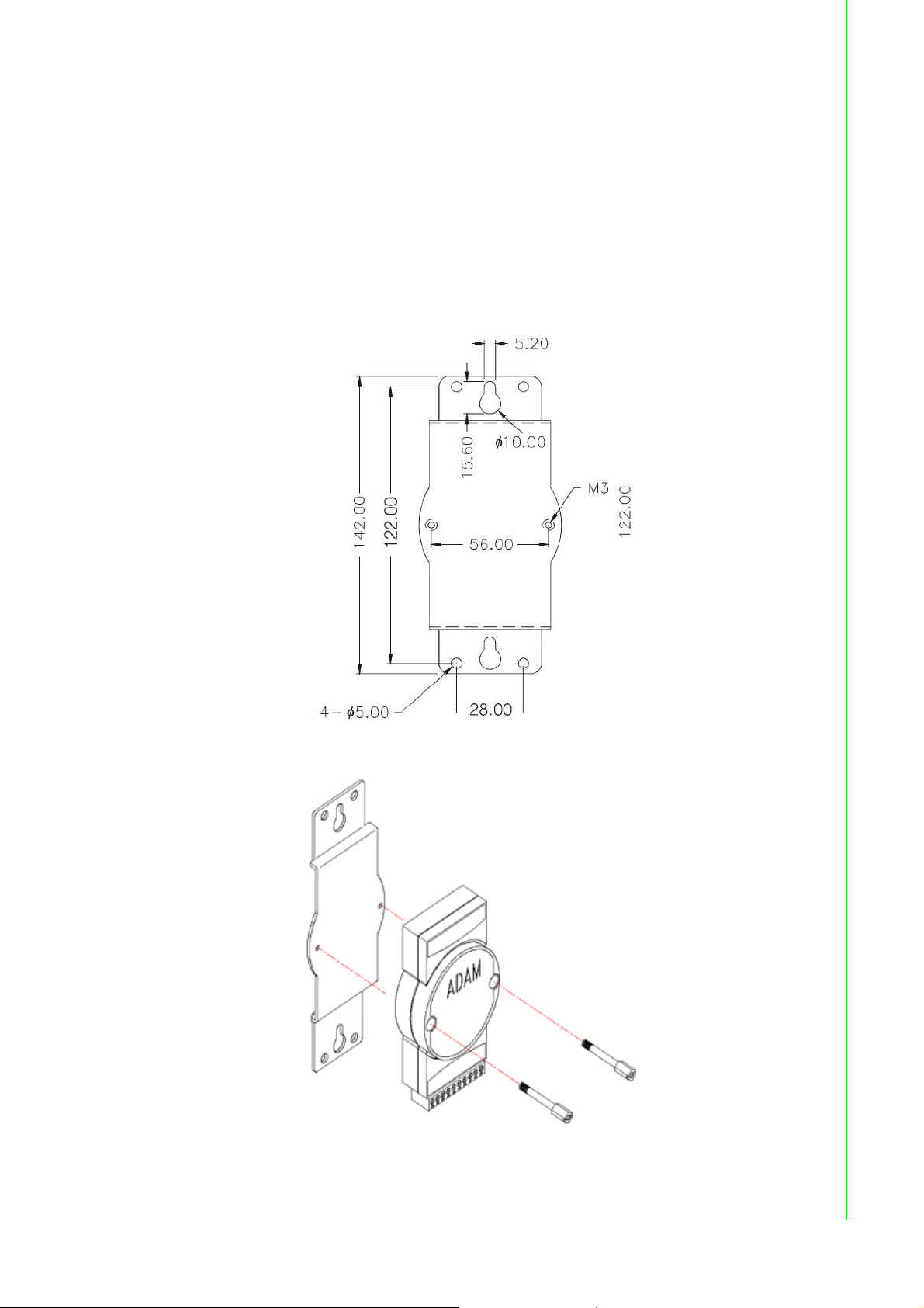
3.2.1 Panel Mounting
Before installing the ADAM-6000 module, you should determine the optimal placement in a panel or cabinet by referring the bracket dimensions shown in Figure 3.1.
First, fix the bracket and then fix the ADAM-6000 module on the bracket, as shown in
Figure 3.2.
Chapter 3 Hardware Installation Guide
Figure 3.1 Panel Mounting Bracket Dimensions
Figure 3.2 How to Fix a Module on the Mounting Bracket
13 ADAM-6000 User Manual
Page 26
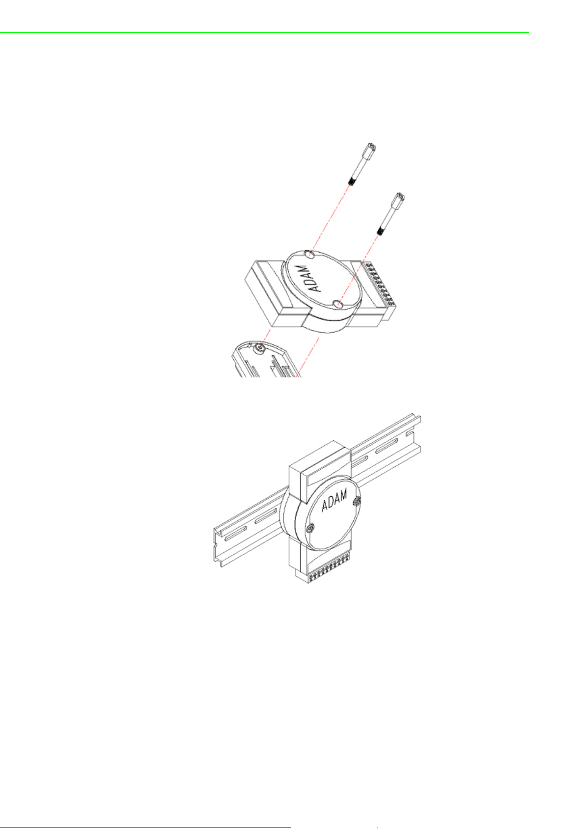
3.2.2 DIN Rail Mounting
The ADAM-6000 module can also be secured to a cabinet by using DIN rails. First,
fix the ADAM-6000 module to the DIN rail adapter (Figure 3-3) and then secure it on
the DIN rail (Figure 3-4). When mounting the module on the rail, you should consider
using end brackets at each end of the rail in order to prevent the module from sliding.
Figure 3.3 How to Fix a Module on the DIN Rail Adapter
Figure 3.4 How to Secure a Module to a DIN Rail
ADAM-6000 User Manual 14
Page 27
3.3 Wiring and Connections
This section provides basic information on wiring the power supply, I/O units, and network connection.
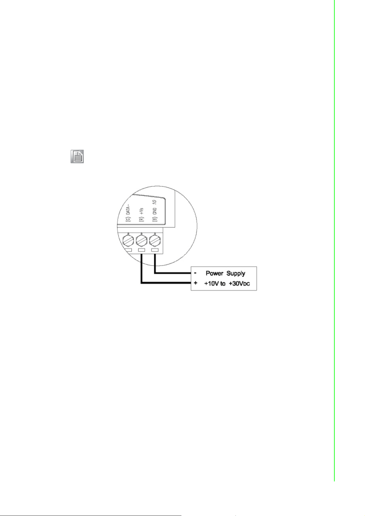
3.3.1 Power Supply Wiring
Although ADAM-6000/TCP systems are designed for a standard industrial unregulated 24 V
within the range of +10 to 30 V
peak-to-peak, and the immediate ripple voltage should be maintained between +10
and 30 V
Note! The wires should be at least 2 mm in diameter.
power supply, they accept any power unit that supplies input power
DC
. Power supply ripple must be limited to 200 mV
DC
. Screw terminals +Vs and GND are for wiring the power supply.
DC
Chapter 3 Hardware Installation Guide
Figure 3.5 How to Connect the Module Power Wires
We advise using the following standard colors (which are also indicated on the modules) for the power lines:
+Vs (R) Red
GND (B)Black
3.3.2 I/O Module Wiring
A plug-in screw terminal block is used for the interface between I/O modules and field
devices. The following information must be considered when connecting electrical
devices to I/O modules.
The terminal block accepts Wire Size #14~28 AWG (stripped length: 6.5 mm)
Always use a continuous length of wire; do not combine wires
Use the shortest possible wire length
Use wire trays for routing where possible
Avoid running wires near high-energy wiring
Avoid running input wiring proximal to output wiring
Avoid creating sharp bends in the wires
15 ADAM-6000 User Manual
Page 28

ADAM-6000 User Manual 16
Page 29

Chapter 4
4 Introduction to Analog
ADAM-6000 I/O
Modules
Page 30

4.1 Analog Input Modules
Analog input modules use an A/D converter to convert sensor voltage, current, thermocouple, and RTD signals into data, which are then translated into engineering
units. When prompted by the host computer, the data are sent via standard 10/
100BASE-T Ethernet or IEEE 802.11b WLAN. The current status can then be read
using a pre-built webpage or any HMI software that supports Modbus/TCP. Analog
input modules protect your equipment from ground loops and power surges by providing opto-isolation of the A/D input as well as transformer-based isolation.
4.2 ADAM-6015 7-ch Isolated RTD Input Module
The ADAM-6015 is a 16-bit, 7-ch RTD input module with programmable input ranges
on all channels. It accepts various RTD inputs (PT100, PT1000, Balco 500, and Ni),
and data are transmitted to the host computer in engineering units (°C). Each analog
channel can be configured to an independent range, thus allowing individual channels to be used simultaneously in different applications.
4.2.1 Specifications
Communication: 10/100BASE-T Ethernet
Supported protocols: Modbus/TCP,TCP/IP, UDP, HTTP, ICMP, DHCP, and ARP
Supports P2P and GCL (see Section 6.7 and Chapter 8)
High-Speed Mode (DE Version Only)
In high-speed mode, the maximum total sample rate is 1 kHz (i.e., if 7 channels are
used, then the sampling rate will be 1000/7, which is approximately 142 Hz per channel). This will be influenced by the number of connected Modbus clients and the
Ethernet quality. To maximize performance in high-speed mode, any channels that
are not in use should be disabled; otherwise, the accuracy may be affected.
Note! When using a calibrator to simulate resistors in high-speed mode, no
more than one channel should be enabled.
ADAM-6000 User Manual 18
Page 31

/
Analog Input
Channels: 7 (differential)
Input impedance: >10 M
Input connections: 2- or 3-wire
Input types: Pt 100/1000, Balco 500, and Ni 518 RTD
RTD types and temperature range:
– Pt 100: -50~150°C
0~100°C
0~200°C
0~400°C
-200~200°C
IEC RTD 100 ( = 0.0385)
JIS RTD 100 ( = 0.0392)
– Pt 1000: -40~160°C
– Balco 500: -30~120°C
– Ni 518: -80~100°C
0~100°C
Accuracy:
– ±0.1% or better
– ±0.5% or better (high-speed mode)
(measured by 3-wire RTD)
Span drift: ±25 ppm/°C
Zero drift: ±6 mV/°C
Resolution: 16-bit
Sample rate (total):
– 10 Hz
– 1 kHz (high-speed mode; DE version only)
CMR @ 50/60 Hz: 90 dB (not supported in high-speed mode)
NMR @ 50/60 Hz: 60 dB (not supported in high-speed mode)
Wire burnout detection
Overvoltage protection: ±35 V
Built-in TVS/ESD protection
DC
Chapter 4 Introduction to Analog ADAM-6000 I
General
Built-in watchdog timer
Isolation protection: 2000 V
Power input: Unregulated 10~30 V
Power consumption: 2.5 W @ 24 V
Power reversal protection
Operating humidity: 20~95% RH (non-condensing)
Storage humidity: 0~95% RH (non-condensing)
Operating temperature: -10~70°C
Storage temperature: -20~80°C
DC
DC
DC
19 ADAM-6000 User Manual
O Modules
Page 32

4.2.2 Application Wiring
Figure 4.1 ADAM-6015 RTD Input Wiring
4.2.3 Address Assignment
Based on the Modbus/TCP standard, the addresses of ADAM-6000 module I/O
channels in the system are defined by a simple rule. See Appendix B.2.1 for information on mapping the I/O addresses.
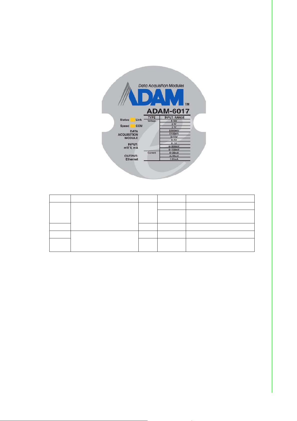
4.3 ADAM-6017 8-ch Analog Input/2-ch Digital
Output Module
The ADAM-6017 is a 16-bit, 8-ch analog differential input module with programmable
input ranges on all channels. The module has been designed with eight analog inputs
and two digital outputs. The accepted input types are millivolt (±150, ±500, 0~150,
0~500 mV), voltage (±1, ±5, ±10, 0~1, 0~5, 0~10 V), and current (0~20, 4~20, ±20
mA) signals, and data are transmitted to the host computer in engineering units (mV,
V, or mA). Each analog channel can be configured to an independent range, thus
allowing individual channels to be used simultaneously in different applications.
4.3.1 Specifications
Communication: 10/100BASE-T Ethernet
Protocols: MQTT, SNMP, Modbus/TCP, TCP/IP, UDP, HTTP, ICMP, DHCP, ARP
Supports P2P and GCL (see Section 6.7 and Chapter 8)
ADAM-6000 User Manual 20
Page 33

/
Analog Input
Channels: 8 (differential)
Input impedance: >10 M (voltage), 120 (current)
Input type: mV, V, mA
Input range: ±150 mV, ±500 mV, ±1 V, ±5 V, ±10 V, 0~150 mV, 0~500 mV, 0~1 V,
0~5 V, 0~10 V, 0~20 mA, 4~20 mA, ±20 mA
Accuracy:
– ±0.1% of FSR (voltage) @ 25°C
– ±0.2% of FSR (current) @ 25°C
Span drift: ±25 ppm/°C
Zero drift: ±6 mV/°C
Resolution: 16-bit
Sample rate (total):
– 10 Hz
– 100 Hz (CE version only)
CMR @ 50/60 Hz: 90 dB
NMR @ 50/60 Hz: 67 dB
Calibration: Auto calibration
Burnout detection (4~20 mA only)
Common-mode voltage: 350 V
DC
Chapter 4 Introduction to Analog ADAM-6000 I
Digital Output
Channels: 2
Sink type: Open collector to 30 V, 100 mA (max. load)
Power dissipation: 300 mW for each module
Output-delay on: 100 µs
Output-delay off: 150 µs
Overvoltage protection (max.): 42 V
Overcurrent protection (max.): 2 A
Leakage current: 200 µA (max.) for D version
General
Isolation protection: 2000 V
Power input: 10~30 V
Power consumption: 2.7 W @ 24 V
Power reversal protection
Operating humidity: 20~95% RH (non-condensing)
Storage humidity: 0~95% RH (non-condensing)
Operating temp (exclusive of RTC function): -20~70°C (-40~70°C for D version)
Storage temp (exclusive of RTC function): -30~80°C (-40~85°C for D version)
Watchdog timer (system): 1.6 s
RTC (D version only): ISO8601 format
DC
DC
DC
DC
O Modules
Note! The operation/storage temperature for the RTC function is -30~70°C.
21 ADAM-6000 User Manual
Page 34

Jumper Settings
ADAM-6017-CE ADAM-6017-AE&BE
Channel Number Select Jumper Channel Number Select Jumper
CH0 CN3 CH0 JP6
CH1 CN4 CH1 JP7
CH2 CN5 CH2 JP8
CH3 CN6 CH3 JP1
CH4 CN7 CH4 JP2
CH5 CN8 CH5 JP3
CH6 CN9 CH6 JP4
CH7 CN10 CH7 JP5
To simplify the jumper settings, for the ADAM-6017 (D version), you can set the analog input type to voltage or current by adjusting the switch without opening the case.
Figure 4.2 ADAM-6017 Jumper Switches
Switch SW1 SW2
Analog input channel CH0 CH1 CH2 CH3 CH4 CH5 CH6 CH7
Switch ON Current input mode
Switch OFF (default) Voltage input mode
Note! Using tools wider than 0.65 mm to adjust the switch will result in damage
to the switch.
ADAM-6000 User Manual 22
Page 35

/
4.3.2 Application Wiring
Figure 4.3 ADAM-6017 Analog Input Wiring
The ADAM-6017 has a 120- resistor built in to each channel; thus, no additional
resistors need to be added for current input measurements. Simply adjust the jumper
setting according to the input type you require. Figure 4.3 shows the jumpers for setting the inputs to voltage mode or current mode.
Chapter 4 Introduction to Analog ADAM-6000 I
O Modules
Figure 4.4 ADAM-6017 Analog Input Type Setting
Figure 4.5 ADAM-6017 Digital Output Wiring
23 ADAM-6000 User Manual
Page 36

4.3.3 Address Assignment
Based on the Modbus/TCP standard, the addresses of ADAM-6000 I/O channels you
place in the system are defined by a simple rule. See Appendix B.2.2 for information
on mapping the I/O addresses.
4.4 ADAM-6018 Isolated Thermocouple Input/8-ch
Digital Output Module
The ADAM-6018 is a 16-bit, 8-ch thermocouple input module with programmable
input ranges on all channels. The module has eight thermocouple inputs (Types J, K,
T, E, R, S, and B) and eight digital outputs. Each input can be configured to an independent range, thus allowing individual channels to be used simultaneously in different applications.
Figure 4.6 ADAM-6018 8-ch Thermocouple Input
4.4.1 Specifications
Communication: 10/100BASE-T Ethernet
Supported protocols: Modbus/TCP, TCP/IP, UDP, HTTP, ICMP, DHCP, and ARP
Supports P2P and GCL (see Section 6.7 and Chapter 8)
ADAM-6000 User Manual 24
Page 37

/
Analog Input
Channels: 8 (differential)
Input impedance: >10 M
Input type: Thermocouple
Thermocouple type and range:
– Type J: 0~760°C
– Type K: 0~1370°C
– Type T: -100~400°C
– Type E: 0~1000°C
– Type R: 500~1750°C
– Type S: 500~1750°C
– Type B: 500~1800°C
Accuracy: ±0.1% or better
Span drift: ±25 ppm/°C
Zero drift: ±6 mV/°C
Resolution: 16-bit
Sample rate: 10 Hz
CMR @ 50/60 Hz: 90 dB
NMR @ 50/60 Hz: 60 dB
Overvoltage protection ±35 V
Built-in TVS/ESD protection
Wire burnout detection
Chapter 4 Introduction to Analog ADAM-6000 I
DC
Digital Output
Channels: 8
Sink type: Open collector to 30 V, 100 mA (max. load)
Power dissipation: 300 mW for each module
General
Built-in watchdog timer
Isolation protection: 2000 V
Power input: Unregulated 10~30 V
Power consumption: 2 W @ 24 V
Power reversal protection
Operating humidity: 20~95% RH (non-condensing)
Storage humidity: 0~95% RH (non-condensing)
Operating temperature: -10~70°C
Storage temperature: -20~80°C
DC
DC
DC
O Modules
25 ADAM-6000 User Manual
Page 38

4.4.2 Application Wiring
Figure 4.7 ADAM-6018 Thermocouple Input Wiring
Figure 4.8 ADAM-6018 Digital Output Wiring
4.4.3 Address Assignment
Based on the Modbus/TCP standard, the addresses of ADAM-6000 I/O channels you
place in the system are defined by a simple rule. See Appendix B.2.3 for information
on mapping the I/O addresses.
4.5 ADAM-6024 12-ch Isolated Universal I/O Module
The ADAM-6024 is a 12-ch universal I/O module with programmable input ranges on
all channels. The module has six analog inputs, two analog outputs, two digital
inputs, and two digital outputs. The analog input channels are 16-bit universal signal
ADAM-6000 User Manual 26
Page 39

/
inputs, accepting voltage (±10 V) and current (0~20, 4~20 mA) signals. The analog
output channels are 12-bit outputs for volts (0~10 V) and current (0~20 mA, 4~20
mA). Each analog channel can be configured to an independent range, thus allowing
individual channels to be used simultaneously in different applications.
4.5.1 Specifications
Communication: 10/100BASE-T Ethernet
Supported protocols: Modbus/TCP,TCP/IP, UDP, HTTP, ICMP, DHCP and ARP
Receives data from other modules that support P2P and GCL functionality, and
generates analog output signals (see Section 6.7 and Chapter 8 for more detail
about P2P and GCL)
Analog Input
Channels: 6 (differential)
Range: ±10 V
Input impedance: >10 M
Accuracy: ±0.1% of FSR
Resolution: 16-bit
CMR @ 50/60 Hz: 90 dB
NMR @ 50/60 Hz: 60 dB
Span drift: ±25 ppm/°C
Zero drift: ±6 mV/°C
Isolation protection: 2000 V
, 0~20 mA, 4~20 mA
DC
DC
Chapter 4 Introduction to Analog ADAM-6000 I
Analog Output
Channels: 2
Range: 0~10 V
Accuracy: ±0.1% of FSR
Resolution: 12-bit
Current load resistor: 500 (max.)
Voltage load resistor: 1 k (min.)
Isolation protection: 2000 V
Drift: ±50 ppm/°C
Digital Input
Channels: 2
Dry contact:
– Logic level 0: close to GND
– Logic level 1: open
Wet contact:
– Logic level 0: 0~3 V
– Logic level 1: 10~30 V
, 0~20 mA, 4~20 mA
DC
DC
DC
DC
O Modules
Digital Output
Channels: 2
Sink type: Open collector to 30 V, 100 mA (max.)
Power dissipation: 300 mW for each module
27 ADAM-6000 User Manual
Page 40

General
Built-in watchdog timer
Isolation protection: 2000 V
Power input: Unregulated 10~30 V
Power consumption: 4 W @ 24 V
DC
DC
DC
Power reversal protection
Operating humidity: 20~95% RH (non-condensing)
Storage humidity: 0~95% RH (non-condensing)
Operating temperature: -10~50°C
Storage temperature: -20~80°C
Jumper Settings
Channel Jumper Current Voltage
AI0 J1 I V
AI1 J2 I V
AI2 J3 I V
AI3 J4 I V
AI4 J5 I V
AI5 J6 I V
AO0 J7 I V
J8 I V
AO1 J9 I V
J10 I V
Figure 4.9 ADAM-6024 Jumper Settings
ADAM-6000 User Manual 28
Page 41

/
4.5.2 Application Wiring
Figure 4.10 ADAM-6024 Analog I/O Wiring
Chapter 4 Introduction to Analog ADAM-6000 I
Figure 4.11 ADAM-6024 Digital Input Wiring
29 ADAM-6000 User Manual
O Modules
Page 42
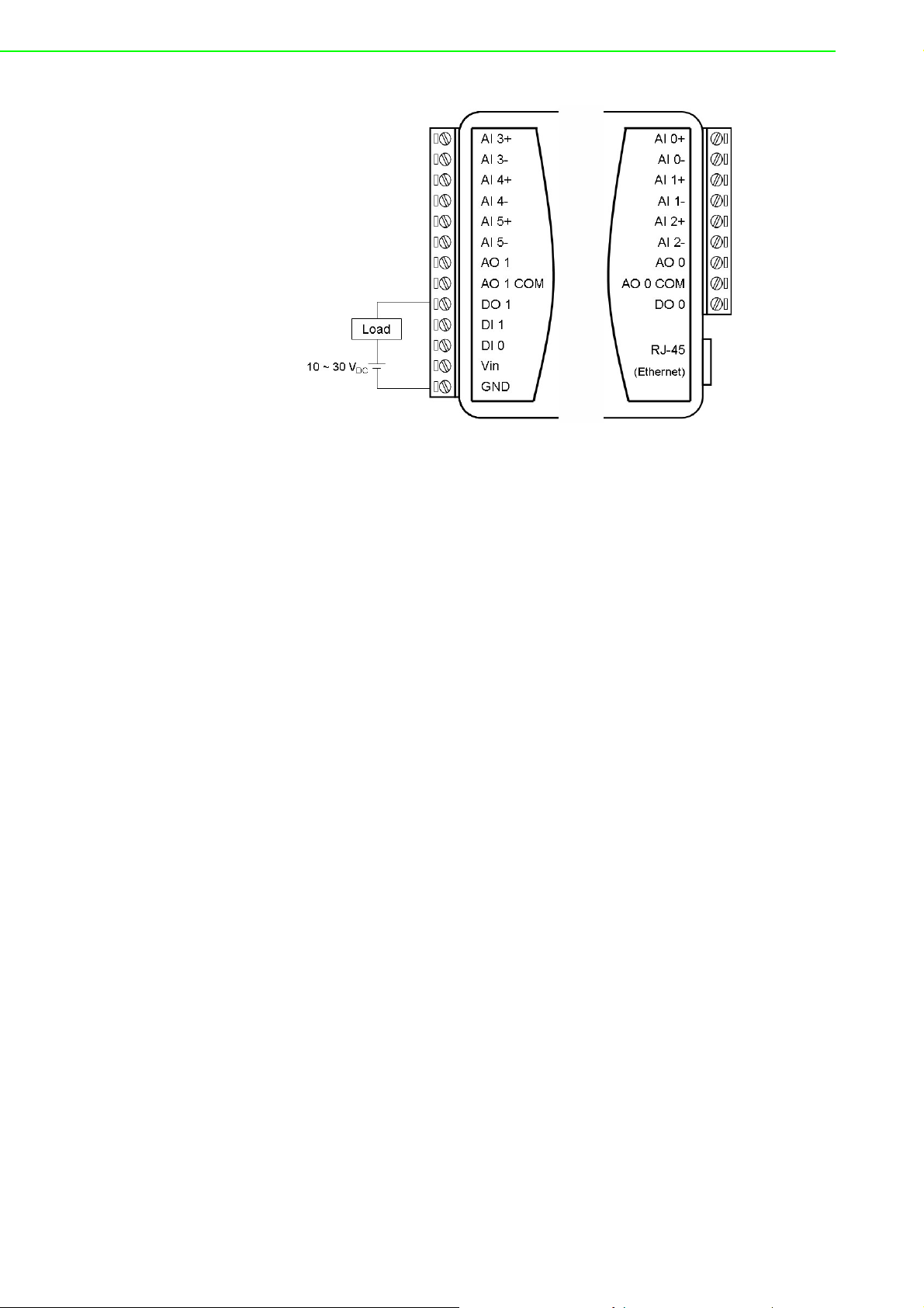
Figure 4.12 ADAM-6024 Digital Output Wiring
4.5.3 Address Assignment
Based on the Modbus/TCP standard, the addresses of ADAM-6000 I/O channels you
place in the system are defined by a simple rule. See Appendix B.2.4 for information
on mapping the I/O addresses.
ADAM-6000 User Manual 30
Page 43

Chapter 5
5 Introduction to Digital
ADAM-6000 I/O
Modules
Page 44

5.1 Digital I/O and Relay Modules
Digital I/O modules can be connected to digital sensors and actuators. These modules support both dry and wet contact for different applications. Relays, on the other
hand, are electrically operated switches. Relay modules are typically employed to
control a circuit by using a low-power signal. When prompted by the host computer,
data are sent through a standard 10/100BASE-T Ethernet or IEEE 802.11b WLAN.
You can read/set the digital I/O status via a pre-built web page or HMI software that
supports the Modbus/TCP protocol.
5.2 ADAM-6050 18-ch Isolated Digital I/O Module
The ADAM-6050 is a high-density I/O module with a built-in 10/100BASE-T interface
for seamless Ethernet connectivity. The module has 12 digital inputs and 6 digital outputs with 2000 V
important signal handling, and they can be used as 3-kHz counter and frequency
input channels. The outputs support pulse output.
5.2.1 Specifications
Communication: 10/100BASE-T Ethernet
Supported protocols: MQTT, SNMP, Modbus/TCP, TCP/IP, UDP, HTTP, ICMP,
DHCP, and ARP
Supports P2P and GCL (see Section 6.7 and Chapter 8)
isolation protection. All inputs have a latch function for handling
DC
Digital Input
Channels: 12
Dry contact:
– Logic level 0: Close to GND
– Logic level 1: Open
Wet contact:
– Logic level 0: 0~3 V
– Logic level 1: 10~30 V
Supports 3-kHz counter input (32-bit with overflow flag)
Frequency input range: 0.2~3 kHz
Supports inverted digital input status
Digital Output
Channels: 6
Sink type: Open collector to 30 V, 100 mA (max. load)
Supports 5-kHz pulse output
Supports high-to-low and low-to-high delay output
Leakage current: 200 A (max.) (D version)
DC
DC
ADAM-6000 User Manual 32
Page 45

/
General
Built-in watchdog timer
Isolation protection: 2000 V
Power input: Unregulated 10~30 V
Power consumption: 2 W (max.) @ 24 V
Power reversal protection
Operating humidity: 20~95% RH (non-condensing)
Storage humidity: 0~95% RH (non-condensing)
Operating temperature: -20~70°C (D version: -40~70°C)
Storage temperature: -30~80°C (D version: -40~85°C)
5.2.2 Application Wiring
Chapter 5 Introduction to Digital ADAM-6000 I
DC
DC
DC
Figure 5.1 ADAM-6050 Digital Input Wiring
O Modules
Figure 5.2 ADAM-6050 Digital Output Wiring
33 ADAM-6000 User Manual
Page 46

5.2.3 Address Assignment
Based on the Modbus/TCP standard, the addresses of ADAM-6000 I/O channels you
place in the system are defined by a simple rule. See Appendix B.2.5 for information
on mapping the I/O addresses. All inputs in the ADAM-6050 can be configured to be
used as 32-bit counters (each counter has two addresses: a low word and a high
word) by using Windows Utility (see Section 6.3).
5.3 ADAM-6051 14-ch Isolated Digital I/O Module w/
2-ch Counter
The ADAM-6051 is a high-density digital I/O module with a built-in 10/100BASE-T
interface for seamless Ethernet connectivity. The module has 12 digital inputs, 2
counter channels, and 2 digital outputs with 2000 V
inputs have a latch function for important signal handling and can be used as 3-kHz
counter and frequency input channels. The digital outputs support pulse output.
5.3.1 Specifications
Communication: 10/100BASE-T Ethernet
Supported protocols: MQTT, SNMP, Modbus/TCP, TCP/IP, UDP, HTTP, ICMP,
DHCP, and ARP
Supports P2P and GCL (see Section 6.7 and Chapter 8)
isolation protection. All digital
DC
Digital Input
Channels: 12
Dry contact:
– Logic level 0: Close to GND
– Logic level 1: Open
Wet contact:
– Logic level 0: 0~3 V
– Logic level 1: 10~30 V
Supports 3-kHz counter input (32-bit with overflow flag)
Supports 3-kHz frequency input
Supports inverted digital input status
Counter Input
Channels: 2 (32-bit with overflow flag)
Maximum count: 4,294,967,295
Frequency range:
– 0.2~4500 Hz (frequency mode)
– 0~4500 Hz (counter mode)
DC
DC
Digital Output
Channels: 2
Sink type: Open Collector to 30 V, 100 mA (maximum load)
Supports 5-kHz pulse output
Supports high-to-low and low-to-high delay output
Leakage current: 200 A (D version)
ADAM-6000 User Manual 34
Page 47
/
General
Built-in watchdog timer
Isolation protection: 2000 V
Power input: Unregulated 10~30 V
Power consumption: 3 W @ 24 V
Power reversal protection
Operating humidity: 20~95% RH (non-condensing)
Storage humidity: 0~95% RH (non-condensing)
Operating temperature: -20~70°C (D version: -40~70°C)
Storage temperature: -30~80°C (D version: -40~85°C)
5.3.2 Application Wiring
Chapter 5 Introduction to Digital ADAM-6000 I
DC
DC
DC
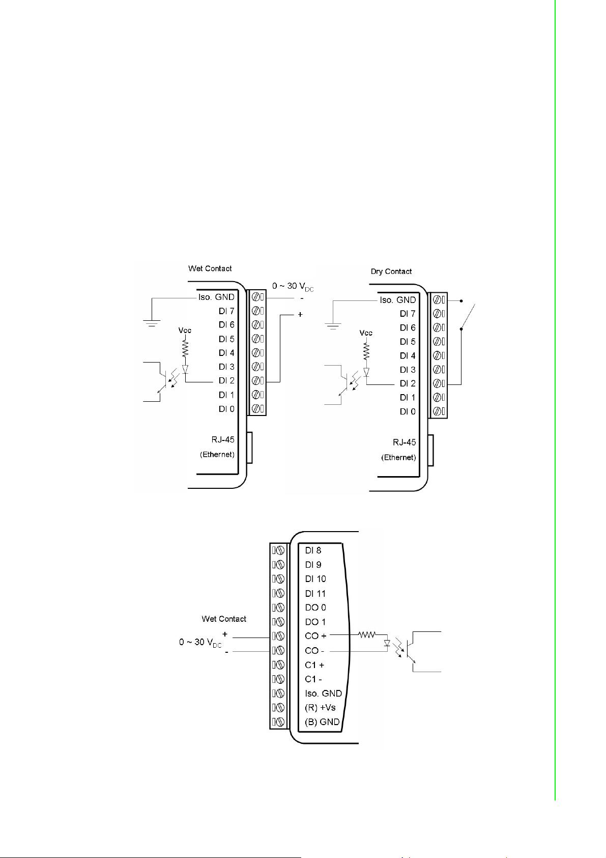
Figure 5.3 ADAM-6051 Digital Input Wiring
O Modules
Figure 5.4 ADAM-6051 Counter (Frequency) Input
35 ADAM-6000 User Manual
Page 48
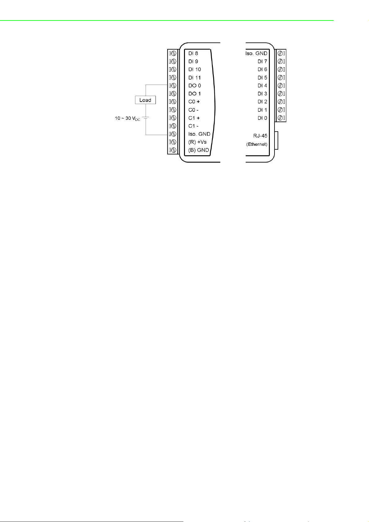
Figure 5.5 ADAM-6051 Digital Output Wiring
5.3.3 Address Assignment
Based on the Modbus/TCP standard, the addresses of ADAM-6000 module I/O
channels you place in the system are defined by a simple rule. Please refer to
Appendix B.2.6 for information on mapping the I/O addresses. All digital inputs in the
ADAM-6051 can be configured to be used as 32-bit counters (each counter has two
addresses: a low word and a high word) by using Windows Utility (see Section 6.3).
5.4 ADAM-6052 16-ch Source-Type Isolated Digital
I/O Module
The ADAM-6052 is a high-density digital I/O module with a built-in 10/100BASE-T
interface for seamless Ethernet connectivity. The module has 8 digital inputs and 8
digital outputs. All inputs have a latch function and can be used as 3-kHz counter and
frequency input channels. The outputs support source-type and pulse output.
5.4.1 Specifications
Communication: 10/100BASE-T Ethernet
Supported protocols: MQTT, SNMP, Modbus/TCP, TCP/IP, UDP, HTTP, ICMP,
DHCP, and ARP
Supports P2P and GCL (see Section 6.7 and Chapter 8)
Digital Input
Channels: 8
Dry contact:
– Logic level 0: Open
– Logic level 1: Close to Ground
Wet contact:
– Logic level 0: 0~3 V
– Logic level 1: 10~30 V
Supports 3-kHz counter input (32-bit with overflow flag)
Supports 3-kHz frequency input
Supports inverted digital input status
DC
DC
ADAM-6000 User Manual 36
Page 49

/
Digital Output
Channels: 8
Source type: 10~35 V
Note: When operating at 70°C, the maximum total current for DO0~DO3 and
DO4~DO7 is recommended to be less than 3 A
Supports 5-kHz pulse output
Supports high-to-low and low-to-high delay output
General
Built-in watchdog timer
Isolation protection: 2000 V
Power input: Unregulated 10~30 V
Power consumption: 2 W @ 24 V
Power reversal protection
Operating humidity: 20~95% RH (non-condensing)
Storage humidity: 0~95% RH (non-condensing)
Operating temperature: -20~70°C (D version: -40~70°C)
Storage temperature: -30~80°C (D version: -40~85°C)
, 1 A (per channel)
DC
DC
DC
DC
Chapter 5 Introduction to Digital ADAM-6000 I
Jumper Settings
O Modules
Figure 5.6 ADAM-6052 Jumper Settings
37 ADAM-6000 User Manual
Page 50

5.4.2 Application Wiring
The ADAM-6052 supports both dry and wet contact for the inputs. You can change
between dry and wet contact mode by adjusting the jumper.
Figure 5.7 ADAM-6052 Digital Input Wiring
ADAM-6000 User Manual 38
Page 51

/
Figure 5.8 ADAM-6052 Digital Output Wiring
5.4.3 Address Assignment
Based on the Modbus/TCP standard, the addresses of ADAM-6000 module I/O
channels are defined by a simple rule. Please refer to Appendix B.2.7 for information
on mapping the I/O addresses. ADAM-6052 inputs can be configured as 32-bit counters (each counter has two addresses: a low word and high word) by using Adam/
Apax .NET Utility (see Section 6.3).
Chapter 5 Introduction to Digital ADAM-6000 I
5.5 ADAM-6060 6-ch Digital Input/6-ch Relay Module
The ADAM-6060 is a high-density I/O module with a 10/100BASE-T interface. Bonding with an Ethernet port and web page, the module provides 6 digital inputs and 6
relay outputs (Form A) and has a contact rating of 120 V
A. All inputs have a latch for important signal handling and can be used as 3-kHz
counter and frequency input channels. The outputs support pulse output.
5.5.1 Specifications
Communication: 10/100BASE-T Ethernet
Supported protocols: MQTT, SNMP, Modbus/TCP, TCP/IP, UDP, HTTP, ICMP,
DHCP, and ARP
Supports P2P and GCL (see Section 6.7 and Chapter 8)
Digital Input
Channels: 6
Dry contact:
– Logic level 0: Close to GND
– Logic level 1: Open
Wet contact:
– Logic level 0: 0~3 V
– Logic level 1: 10~30 V
Supports 3-kHz counter input (32-bit with overflow flag)
Frequency input range: 0.2 Hz~3 kHz
Support inverted digital input status
Keep/discard counter value when powered off
DC
DC
@ 0.5 A and 30 VDC @ 1
AC
O Modules
39 ADAM-6000 User Manual
Page 52

Relay Output
Channels: 6 (Form A)
Contact rating (Resistive):
– 120 V
– 30 V
Breakdown voltage: 500 V
AC
@ 1 A
DC
@ 0.5 A
(50/60 Hz)
AC
Relay-on time: 7 ms
Relay-off time: 3 ms
Total switching time: 10 ms
Insulation resistance: 1 G (min.) @ 500 V
DC
Maximum switching rate: 20 operations/min (at rated load)
Electrical endurance
– At 12 V/10 mA: 5 x 10⁷ operations (typical)
– At 6 V/100 mA: 1 x 10⁷ operations (typical)
– At 60 V/500 mA: 5 x 10⁵ operations (typical)
– At 30 V/1000 mA: 1 x 10⁶ operations (typical)
– At 30 V/2000 mA: 2 x 10⁵ operations (typical)
Mechanical endurance
– 108 operations (typical)
Supports pulse output (max. 3 Hz)
General
Built-in watchdog timer
Isolation protection: 2000 V
Power input: Unregulated 10~30 V
Power consumption: 3 W (max.) @ 24 V
DC
DC
DC
Power reversal protection
Operating humidity: 20~95% RH (non-condensing)
Storage humidity: 0~95% RH (non-condensing)
Operating temperature: -20~70°C (D version: -40~70°C)
Storage temperature: -30~80° C (D version: -40~85°C)
ADAM-6000 User Manual 40
Page 53

/
5.5.2 Application Wiring
Figure 5.9 ADAM-6060 Digital Input Wiring
Chapter 5 Introduction to Digital ADAM-6000 I
Figure 5.10 ADAM-6060 Relay Output Wiring
5.5.3 Address Assignment
Based on the Modbus/TCP standard, the addresses of ADAM-6000 module I/O
channels you place in the system are defined by a simple rule. Refer to Appendix
B.2.8 for information on mapping the I/O addresses. All inputs in the ADAM-6060 can
be configured to be used as 32-bit counters (each counter consists of two addresses:
a low word and a high word) by using Windows Utility (see Section 6.3).
O Modules
41 ADAM-6000 User Manual
Page 54

5.6 ADAM-6066 6-ch Digital Input/6-ch Power Relay
Module
The ADAM-6066 is a high-density I/O module with a 10/100BASE-T interface for
seamless Ethernet connectivity. It has 6 digital inputs and 6 high-voltage relay outputs (Form A). The module has a contact rating of 250 V
All inputs have a latch function for important signal handling and can be used as 3kHz counter and frequency input channels. The outputs support pulse output.
5.6.1 Specifications:
Communication: 10/100BASE-T Ethernet
Supported protocols: MQTT,SNMP,Modbus/TCP, TCP/IP, UDP, HTTP, ICMP,
DHCP, and ARP Modbus/TCP,SNMP,TCP/IP, UDP, HTTP, ICMP, DHCP and
ARP
Supports P2P and GCL (see Section 6.7 and Chapter 8)
Digital Input
Channels: 6
Dry contact:
– Logic level 0: Close to GND
– Logic level 1: Open
Wet contact:
– Logic level 0: 0~3 V
– Logic level 1: 10~30 V
Supports 3-kHz counter input (32-bit with overflow flag)
Supports 3-kHz frequency input
Supports inverted digital input status
DC
DC
@5A and 30 VDC @ 3 A.
AC
Relay Output
Channels: 6 (Form A)
Contact rating (Resistive):
– 250 V
– 30 V
Breakdown voltage: 500 V
Relay on time: 7 ms
Relay off time: 3 ms
Total switching time: 10 ms
Insulation resistance: 1 G (min.) at 500 V
Maximum switching rate: 20 operations/min (at rated load)
Electrical endurance: 1 x 10⁵ operations
Mechanical endurance
– 2 x 10⁷ operations (typical)
– (Under no load at an operating frequency of 180 operations/min)
Supports pulse output (max. 3 Hz)
AC
@ 3 A
DC
@ 5 A
(50/60 Hz)
AC
DC
ADAM-6000 User Manual 42
Page 55

/
General
Built-in watchdog timer
Isolation protection: 2000 V
Power input: Unregulated 10~30 V
Power consumption: 2.5 W @ 24 V
Power reversal protection
Operating humidity: 20~95% RH (non-condensing)
Storage humidity: 0~95% RH (non-condensing)
Operating temperature: -20~70°C (D version: -40~70°C)
Storage temperature: -30~80°C (D version:-40~85°C)
5.6.2 Application Wiring
Chapter 5 Introduction to Digital ADAM-6000 I
DC
DC
DC
Figure 5.11 ADAM-6066 Digital Input Wiring
O Modules
Figure 5.12 ADAM-6066 Relay Output Wiring
43 ADAM-6000 User Manual
Page 56

5.7 Digital Output Diagnostic Function
When a digital output is active, a circuit wire break or short to ground will cause the
output to fail. To help clarify such a situation quickly, ADAM-6000 modules (all D versions) have a digital output diagnostic function that can detect abnormalities in the
digital output and issue a notification. The diagnostic status is given according to the
following groups:
Module Diagnostic Group Output Channel
ADAM-6017 Group 0 DO0, DO1
Group 0 DO0, DO1
ADAM-6050
ADAM-6051 Group 0 DO0, DO1
ADAM-6052
Group 1 DO2, DO3
Group 2 DO4, DO5
Group 0 DO0
Group 1 DO1
Group 2 DO2
Group 3 DO3
Group 4 DO4
Group 5 DO5
Group 6 DO6
Group 7 DO7
Note that for the ADAM-6050 and ADAM-6051, each group corresponds to a pair of
digital outputs, whereas for the ADAM-6052, each group corresponds to an individual
channel. When an error occurs with one or both channels in a group, the diagnostic
status for that group will change. Possible reasons for an abnormality are given as
follows.
For the ADAM-6017, ADAM-6050, and ADAM-6051
When the digital output is not active:
The digital output circuit wire break has occurred (open load)
The digital output connection is short to ground
When the digital output is active:
The output has been exposed to an overcurrent (>1 A)
Note: To ensure that the digital outputs and diagnostic function operate normally,
each digital output should be configured within the specification for individual channels: 30 V, 100 mA (max.).
For the ADAM-6052
When the digital output is active:
The digital output connection is short to ground
The output has been exposed to an overcurrent (>1 A, typical)
ADAM-6000 User Manual 44
Page 57

/
5.7.1 How to Obtain the Digital Output Diagnostic Status
The digital output diagnostic status can be obtained using Adam/Apax .Net Utility, the
Modbus address, or an ASCII command.
Obtaining the Digital Output Diagnostic Status With Adam/Apax .NET Utility
Since Version 2.05.10B08, Adam/Apax .NET Utility has had a digital output diagnostic function. In the example shown in Figure 5.13, the digital output diagnostic status
is abnormal for Group 1 (DO2~DO3) and Group2 (DO4~DO5) (note that individual
groups will appear in this field only if their status is abnormal; thus, Group 0 does not
appear in this example). This indicates that a problem has occurred with one of these
output channels.
Chapter 5 Introduction to Digital ADAM-6000 I
Figure 5.13 Abnormal DO Diagnostic Status
O Modules
45 ADAM-6000 User Manual
Page 58
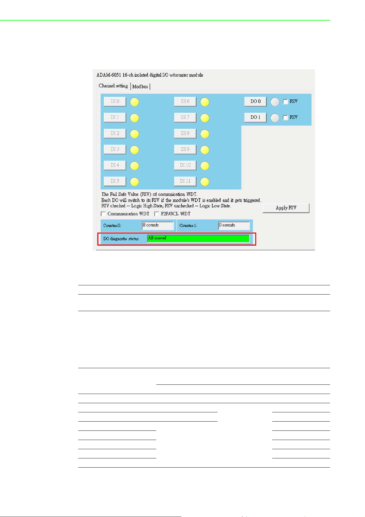
In Figure 5.14 the digital output diagnostic status is "All normal" meaning that all
channels in the group are connected correctly (no wire break or short to ground)
before the digital outputs are activated.
Figure 5.14 Normal DO Diagnostic Status
Obtaining the Digital Output Diagnostic Status With a Modbus Address Value
Address (4X) Channels Description Attribute
40307 All
Digital output diagnostic status (for
D version)
Read
The following table shows the bit positions relative to the groups for the ADAM-6050,
ADAM-6051, and ADAM-6052. The status of the groups can thus be interpreted
according to the value shown in each bit position. The group status values will be displayed as binary values, with Bit 1 being the right-most bit position and Bit 8 being the
left-most bit position.
Bit Position for Modbus
Address 40307
Bit 1 Group 0 Group 0 Group 0
Bit 2 Group 1
Bit 3 Group 2 Group 2
Bit 4
Bit 5 Group 4
Bit 6 Group 5
Bit 7 Group 6
Bit 8 Group 7
Relative Group for Interpreting the Digital Output Diagnostic
Status Value
ADAM-6050 ADAM-6051 ADAM-6052
Group 1
Group 3
Reserved
Reserved
ADAM-6000 User Manual 46
Page 59

/
Example (ADAM-6050): In the case of the previous example shown in Figure 5.13,
the group status values would be "xxxxx110". Here, Bits 1, 2, and 3 indicate the digital output diagnostic status of Groups 0, 1, and 2, respectively. The group status can
thus be interpreted as follows:
Group 0 = 0 (Normal)
Group 1 = 1 (Abnormal)
Group2 = 1 (Abnormal)
Obtaining the Digital Output Diagnostic Status With an ASCII Command
This example shows the ASCII command and response for requesting the status of
digital outputs.
Syntax $017
Response !01(Group#n)…(Group #1)(Group#0)(cr)
Example
Because the ADAM-6050 has three digital output groups for the diagnostic status,
the bit positions from right to left indicate the status of Groups 0~2 are as follows:
Group 0 = 0 (Normal)
Group 1 = 1 (Abnormal)
Group 2 = 1 (Abnormal)
Command: $017
Response: !01110
Chapter 5 Introduction to Digital ADAM-6000 I
47 ADAM-6000 User Manual
O Modules
Page 60

ADAM-6000 User Manual 48
Page 61

Chapter 6
6 System Configuration
Guide
Page 62

6.1 System Requirements
Host Computer
Microsoft Windows XP/7
32 MB RAM
20 MB hard disk space
VGA color monitor
Mouse or other pointing device
10/100-Mbps Ethernet Card
Communication Interface
10/1000-Mbps Ethernet hub (min. 2 ports)
Two Ethernet cables (RJ-45)
Crossover Ethernet cable (RJ-45)
6.2 Installing Adam/Apax .NET Utility
Adam/Apax .NET Utility is an application provided by Advantech for the configuration
and operation of ADAM modules. The installation file can be found on the companion
CD with your ADAM module, and it is also available for download for free at http://
www.advantech.com (click on Download Area under Service & Support for the latest
version). Once installed, a shortcut to the utility will appear on your desktop.
Note: Before installing Adam/Apax .NET Utility, you will need to install .NET Framework 2.0 or later.
6.3 Adam/Apax .NET Utility Overview
Adam/Apax .NET Utility is a graphical interface for configuring and operating ADAM
modules. It is also a convenient tool for testing and monitoring remote DA&C systems. The following text instructions describe how to use the utility.
To start Adam/Apax .NET Utility, double-click the shortcut on the desktop or click the
icon in the start menu folder. When the program is first opened, the main window will
appear as shown in Figure 6.1.
ADAM-6000 User Manual 50
Page 63

Chapter 6 System Configuration Guide
As shown in the figure, this window has four main areas: 1) the Menu Bar, 2) the
Toolbar, 3) the Module Tree Display Area, and 4) the Status Display Area.
6.3.1 Menu Bar
The menu bar comprises four menus: File, Tools, Setup, and Help. The items under
each menu are described as follows:
File Menu
Open Favorite Group Allows you to load a saved configuration file for a favorite group
Save Favorite Group Allows you to save a favorite group into a configuration file
Auto-Initial Group
Exit Exit Adam/Apax .NET Utility
Tools Menu
Search Device
Add Devices to Group
Group Configuration
Terminal for Command
Testing
Print Screen Exports the Adam/Apax .NET Utility screen as an image file
Figure 6.1 Adam/Apax .NET Utility Operation Window
Checking this option will load the same favorite group configuration
next time you launch Adam/Apax .NET Utility
Search for all ADAM modules connected to the host PC (see Section 6.3.5)
Adds ADAM modules to the favorite group; only selected devices in
the Module Tree Display Area will be added to the group
This item is for updating the firmware, configuration, and HTML
files of a single module or multiple modules. The configuration file
includes settings on device information, general information, P2P
and streaming, GCL, and Modbus address XML files. The configuration file can be exported as a Cfg file from the Firmware tab in
the Status Display Area.
Launches a terminal for communicating with ADAM modules via
ASCII command and Modbus/TCP (see Sections 7.3 and 7.4 for
more information)
51 ADAM-6000 User Manual
Page 64

ADAM modules support a datastream function. This allows you to
define the host (such as a PC) by IP, and ADAM modules will then
Monitor Stream/Event
Data
Monitor Peer to Peer
Monitor GCL IO Data
Message
periodically transmit their I/O status to the host. The IP address
and transmission period can be configured from the Stream tab in
the Status Display Area. The Stream tab is introduced in Section
6.3.5.
Select this option to receive messages from ADAM modules that
have the P2P (event trigger) function enabled
Select this option to receive I/O data messages from ADAM mod-
ules that have the GCL function enabled.
Note! When you enable the GCL function, the datastream function will auto-
matically be disabled until you disable the GLC function.
Setup Menu
This is for configuring your Favorite group, including adding
Favorite Group
Refresh Serial and
Ethernet
Add COM Ports
Show TreeView Clicking on this item shows the Module Tree Display Area
Allow Calibration Select this to enable/disable module calibration
devices, modifying or deleting current devices, sorting current
devices, and diagnosing device connections
This will cause Adam/Apax .NET Utility to refresh the serial and
LAN network connection
This is for adding serial COM ports to Adam/Apax .NET Utility (this
does not apply to ADAM-6000 modules)
Help Menu
Check Up-to-Date on
the Web
About
6.3.2 Toolbar
The toolbar (Figure 6.2) contains icons for the most commonly used menu items.
Connect to the Advantech download website and checks for the
latest version of the utility.
This shows information on the version of Adam/Apax .NET Utility
currently installed on your computer
Figure 6.2 Adam/Apax .NET Utility Toolbar
ADAM-6000 User Manual 52
Page 65

6.3.3 Module Tree Display Area
Figure 6.3 Adam/Apax .NET Utility Module Display Area
The Module Tree Display Area is the left part of the main window. There are five
major categories in the display area, some of which will be visible only when you
have certain modules connected:
All serial I/O modules (ADAM-4000, ADAM-4100, and ADAM-5000
Serial
Ethernet
Favorite Group
ADAM4500_5510Series
Wireless Sensor Networks
RS-485 modules) connected to the host PC will be listed in this category.
All Ethernet I/O Modules (ADAM-5000, ADAM-6000, and ADAM6100 TCP modules) connected to the host PC will be listed in this
category.
Devices you have added to your personal favorite group are listed
under this category, making it easier for you to locate specific modules. The favorite group can contain multiple groups. To create a
new group, right-click on Favorite Group and select Add New
Group. You will then be prompted to enter a name for the group. To
add devices to that group, right-click on the group you have created and select Add New Device. You will then be prompted to
give the new device a name and select the module type from either
the Serial Device tab or the Ethernet Device tab. You can also
enter the device parameters here. In addition to modifying the
group (select Modify Group) and deleting the group (select Delete
Group), you can also select diagnose the connection for a group
(select Diagnose Connection) by right-clicking on the group
name.
Any DOS-based remote controllers (e.g., ADAM-4500 and ADAM5510 series) will be listed under this category.
Any wireless modules (e.g., WISE-4000 series) connected to the
host PC will be listed under this category.
Chapter 6 System Configuration Guide
6.3.4 Status Display Area
The Status Display Area is the main window that you will interact with. All configuration and testing is performed here. The content of this window will vary depending on
which items you select in the Module Tree Display Area.
6.3.5 Configuration of ADAM-6000 Modules
Once an ADAM-6000 module has been connected to the host PC and you have
searched for it, you will find it listed in the Module Tree Display Area under the Ethernet category. Select the Ethernet category on the Module Tree Display Area and click
the Search Modules icon on the Toolbar. Adam/Apax .NET Utility will then
search for all ADAM-6000 modules on the Ethernet network. If this is the first time
you have connected the module, its IP will be 10.0.0.1 by default and it will appear
under Others in the Module Tree Display Area.
53 ADAM-6000 User Manual
Page 66

Note! If a network firewall is enabled, you might not be able to connect to your
ADAM-6000 module. You may need to add an exception for Adam/Apax
.NET Utility in Windows Firewall via Windows Control Panel.
Figure 6.4 Adam/Apax .NET Utility - Searching for Devices
You need to change the IP address of the ADAM-6000 module so that it is the same
subnet as the host PC. Enter the correct IP address, subnet address, and default
gateway on the Status Display Area and then click Apply Change. A dialog box will
appear asking you to enter the password. The default password of ADAM-6000 modules is "00000000" (without quotation marks). After you have entered the correct
password, the ADAM-6000 module will be under IP of your host PC. Note that you
can change the password later.
When you select the IP address of the ADAM-6000 modules you want use in Module
Tree Display Area, eight tabs will become available in the Status Display Area. These
tabs are for the general configuration of that module. Once you have changed any
settings, remember to click Apply or Apply Change. These eight tabs are detailed in
the following sections.
ADAM-6000 User Manual 54
Page 67

The Information Tab
Chapter 6 System Configuration Guide
This tab shows the firmware version as well as the device name and device description, both of which can be modified from here. Giving your modules a specific name
and description can be useful for when several ADAM-6000 modules are connected
to the same network. You can also enable/disable the locate function, which is
intended to help you to physically locate the selected module (basically, when you
click Enable, the module’s Status/Link LED indicator will be red for 30 s; see Section
1.5 for a description of the LED status). The tab also shows a QR code that will be
generated for the URL of the selected module's web server. Note that individual module configurations can be saved/loaded from the Firmware tab (explained later in this
section). The configuration file contains settings of network, stream/event data,
access control, and I/O configuration.
55 ADAM-6000 User Manual
Page 68

The Network Tab
This tab contains two main panels: the Network Settings panel and the Application
Network Settings panel. The content of these panels is described in the following
text.
The Network Setting Panel
This panel is for adjusting typical network configuration settings for ADAM modules.
Here, you can set the network connection protocol (DHCP or static IP), IP address,
subnet address, default gateway, and host idle time (timeout).
The Application Network Settings Panel
This panel is for configuring the datastream and P2P/GCL port. When Network Diagnostic is selected, the ADAM module will periodically monitor and diagnose the
Ethernet switch. If the Ethernet port is not used for communication, this function
should be disabled.
Note 1: When a web browser is used to open the web page on an ADAM-6000 module, a Java virtual machine (JVM) will use several TCP connections to download a
Jar file. These connections will be released after the Jar file has been downloaded.
Note 2: After the GCL/P2P port settings have been modified, the module will reboot
automatically (connection recovery time: 3 s).
ADAM-6000 User Manual 56
Page 69

The Stream Tab
Chapter 6 System Configuration Guide
ADAM-6000 modules can be configured to periodically transmit data to up to eight
hosts. This sequence of signals is called a datastream. On the Stream tab, the Hosts
to receive data panel allows you to define the IP addresses of hosts that will receive
data from ADAM-6000 modules. On the Data Streaming tab (right-hand side), you
can also set the intervals at which ADAM-6000 modules will transmit data to the
Hosts.
Note! In the above image, the ADAM-5000/TCP Event Trigger tab is specifi-
cally for the ADAM-5000.
57 ADAM-6000 User Manual
Page 70

The Administration Tab
Note! The default password is “00000000”
The Administration tab allows you to set the password for the selected ADAM-6000
module. To change the password, you will need to enter the current password in the
Old password box and then enter the new password in the New password and Verify
password boxes. The password is required for many configurations and operations,
so setting your own password can help ensure system security. You can also apply
the factory default settings and restart the module from the tab.
Reset to Default Factory Settings
Click Apply on this panel to clear the system configuration of the selected ADAM6000 module and restore the factory default settings.
System Restart
Click Apply to restart the module. Note that your current settings will be preserved.
ADAM-6000 User Manual 58
Page 71

The Firmware Tab
Chapter 6 System Configuration Guide
Advantech will occasionally release new firmware versions to add or improve the
functionality of ADAM-6000 modules. Visit http://www.advantech.com to check for
the latest firmware downloads. Firmware downloads will contain four file types: Bin,
Html, Xml, and Jar. The Bin file is the actual firmware file and the Html and Jar files
are for the web server on the ADAM-6000 module.
The File Import Panel
This is where you can import firmware to your ADAM-6000 module. Click Browse to
select the three firmware files on your computer. Then, click Download to install the
new firmware on the ADAM-6000 module.
The File Export Panel
This is panel is where you can export an ADAM module configuration file. Click Save
As… and choose the destination file path. Then, click Upload to save the configuration file.
59 ADAM-6000 User Manual
Page 72

The Peer to Peer/Event Tab
You can enable and configure the P2P (event) function in this tab. For more details
about the P2P (event) function, see Section 6.7.
ADAM-6000 User Manual 60
Page 73

The Access Control Tab
Chapter 6 System Configuration Guide
This tab is for setting which computers/devices can control the selected ADAM-6000
module. First, select either the IP address or MAC address in the Controlled By
panel and then click Apply. Then, in the Security IP/MAC Setting panel, you will
need to select the Enable/Disable check box and then directly enter the IP or MAC
address of the authorized computers/devices. Finally, click Apply to apply the
changes to a single IP/MAC address or click Apply all to apply all changes. In the
above image, only IP Addresses 172.18.3.52 and 172.18.3.116 are authorized to
control the selected ADAM-6000 module. If no check boxes were selected, then any
computer/device would be able to control the selected module.
61 ADAM-6000 User Manual
Page 74
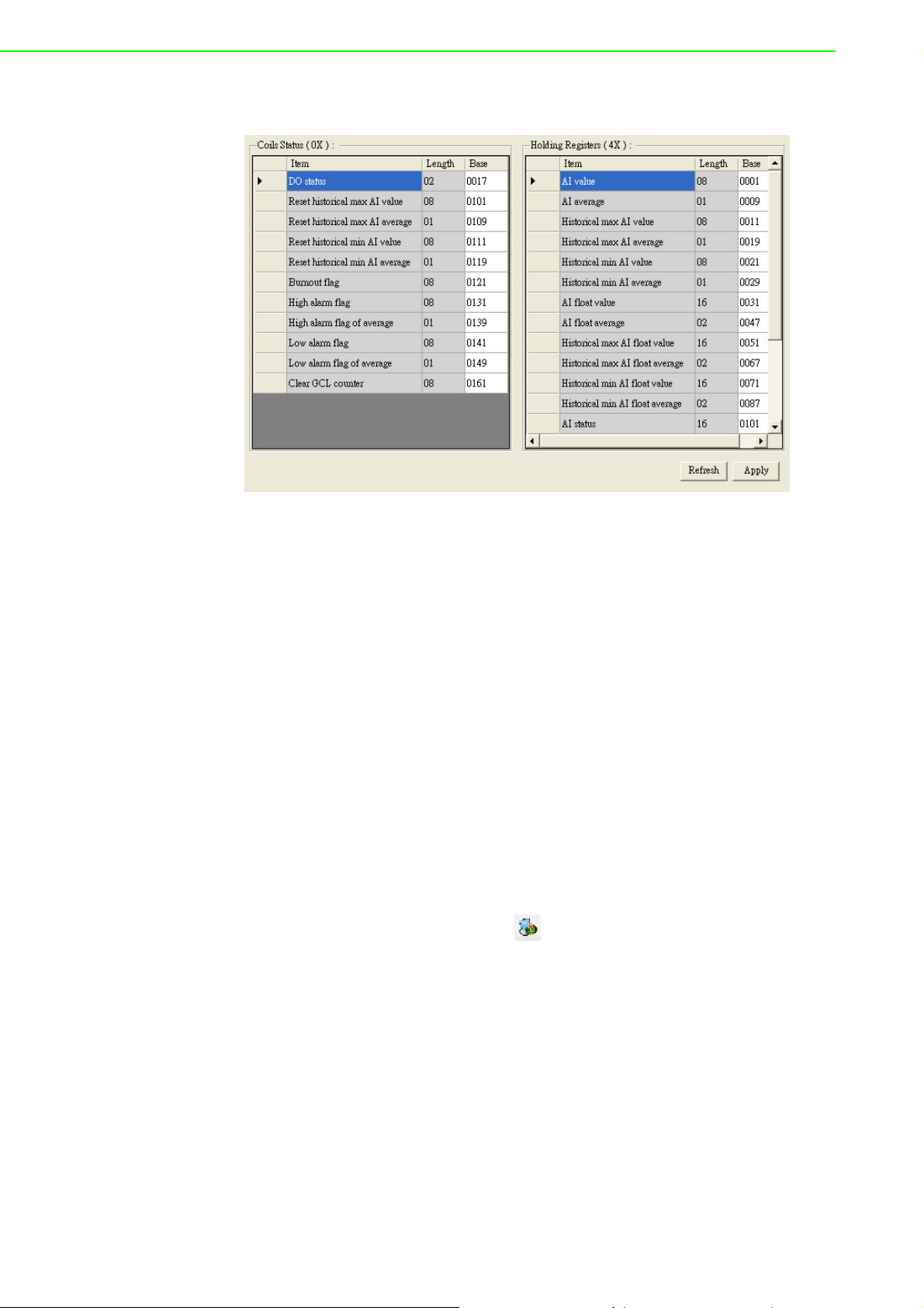
The Modbus Address Tab
To provide greater flexibility and scalability in deploying ADAM modules, the limitations of Modbus address settings have been removed to make the modules as configurable as possible. Basically, there are two types of Modbus address section (0X
and 4X) for configuring each function. For example, the above image shows the Modbus address settings for the ADAM-6017.
6.3.6 Group Configuration
In certain applications, it is necessary to apply the same settings to multiple modules
because they are performing the same tasks at different sites. Previously, users
would have to configure each module individually prior to on-site deployment. After
the modules are installed and the system is running, it will still require repetitive effort
to carry out firmware updates.
To overcome this, ADAM-6000 modules are equipped with a group configuration
function to reduce repetition and accelerate the configuration of multiple modules;
this includes firmware upgrades, configuration files, and HTML 5 files, all of which
can be updated in a single process. Follow these instructions to open the Group Configuration window:
1. Click on Ethernet on the Module Tree Display Area.
2. Click the Group Configuration icon on the toolbar or select Group Con-
figuration under the Too ls menu. This will open the following window:
ADAM-6000 User Manual 62
Page 75

Chapter 6 System Configuration Guide
3. Select Firmware, Configuration, or HTML File (depending on what you wish to
update; in this example, Configuration is selected)
4. Select the type of I/O module you wish to apply the update to (this will select all
modules of this type on the network)
5. Click Browse and you will be prompted to select the firmware/configuration file
you wish to use
6. Choose which modules you wish to reconfigure/update for and enter the pass-
word; note that the default password is "00000000" (without the quotation
marks)
7. Click Apply to apply the changes, and then you will see the operating progress
on the Status Display Area.
63 ADAM-6000 User Manual
Page 76

Note! Do not remove the power from your module when the group configura-
tion function is processing. Otherwise, the module will probably crash.
6.3.7 I/O Configuration
After you have completed the general configuration of the selected ADAM-6000 module (as described in the previous section), you will need to configure the I/O channels
(e.g., channel range, calibration, and alarm settings). At the same time, you can see
input channel value and set value of output channel in the Status panel. Refer to the
Module Tree Display Area shown in Figure 6.5. When you click on the IP address of
the ADAM-6000 module you wish to configure, you will see two items below the IP
address: the module number (for all-channel configuration) and the module number
followed by "GCL" (for GCL configuration). When you click on the plus and minus
control beside the module number, you will be prompted to enter the password for the
selected module. Once you have entered the correct password, a list of individual
channels (for individual channel configuration) will appear below the module number.
Figure 6.5 All-Channel, Individual Channel, and GCL Configuration Controls
When you click on the module number, the analog input value and configuration settings for all channels will be shown in the Status Display Area. When you click on one
of the individual channel items, the values and configuration settings for only the
specified channel will be shown in the Status Display Area. The following sections
describe the all-channel configuration and individual channel configuration in more
detail.
ADAM-6000 User Manual 64
Page 77

6.4 Analog Input Modules (ADAM-6015, ADAM-
6017, and ADAM-6018)
6.4.1 All-Channel Configuration
For these ADAM-6000 modules, when you click an all-channel configuration item in
the Module Tree Display Area, the four main parts of interest in the Status Display
Area will be the Input Range, Integration Time, Calibration, and Channel Informa-
tion panels.
Chapter 6 System Configuration Guide
Figure 6.6 Channels Range Configuration Area
Input Range
This panel allows you to set a different range for each channel. To do this, select the
channel number from the Channel box, select the range from the Range box, and
then click Apply to accept the changes.
Integration Time
To remove noise from the power supply, ADAM-6000 series analog input modules
feature a built-in filter (50 and 60 Hz). For this setting, select the filter you wish to
apply from the Integration Time box. Then, click Apply to accept the changes.
Calibration
Before you can adjust the calibration settings, you will need to enable the calibration
function. To do this, click Allow Calibration under the Setup menu.
65 ADAM-6000 User Manual
Page 78

For the ADAM-6015, ADAM-6018, and ADAM-6024, follow these steps to perform
calibration:
Zero Calibration
1. Click Zero in the Calibration panel
2. Connect a signal with the minimum value of the full scale range (e.g., 0 V) to the
channel requiring calibration
3. Once you have completed the wiring, click Apply to start the calibration
Span Calibration
1. Click Span in the Calibration panel
2. Connect a signal with the maximum value of the full scale range (e.g., 10 V) to
the channel requiring calibration.
3. Once you have completed the wiring, click Apply to start the calibration
For the ADAM-6017, you can perform auto calibration instead of manual calibration.
To do this, click Auto in the Calibration panel.
Channel Information
This panel contains five tabs for viewing and configuring the analog input value of all
channels: the Channel setting tab, the Average setting tab, the Modbus (Present)
tab, the Modbus (Max) tab, and the Modbus (Min) tab.
ADAM-6000 User Manual 66
Page 79

The Channel Setting Tab
This tab displays the current values of the analog input channels. For the ADAM6017 and ADAM-6018, the values of digital input channels are also displayed in this
tab. Simply select the channels you want to monitor and click Apply.
You can also view historical trends for the selected channels by clicking Trend Log.
As shown in Figure 6.7, you can select which channels you wish to log by checking
them in the Channel setting panel on the right side of the screen and clicking Apply.
Then, click Start and the data logging will commence, thus allowing you to view realtime historical trends. You can then click Stop and then Save to file to save the trend
data to your computer.
Clicking Show History and Clear History will show/clear the historical trend data,
whereas clicking Save History will allow you to save the data as a Csv file. To clear
the chart, click Clear Graph. On the right-hand side of the screen you can enter the
number of data points you wish to collect in the BufferSize box, and you can also set
the data polling interval in the PollingInterval box.
Chapter 6 System Configuration Guide
67 ADAM-6000 User Manual
Page 80

Figure 6.7 Analog Input Trend Log
With the wire burnout detection function of the ADAM-6015 and ADAM-6018, if there
is no sensor connected to an input channel, you will see the message "Burn out"
appear in the Information box of the related channel.
The Average Setting Tab
The ADAM-6015, ADAM-6017, and ADAM-6018 feature an averaging function that is
executed by the built-in processor. To use this function, simply check the channels of
interest in the Average setting tab. In the example above, the averaging function
has been enabled for four channels (Channels 0~3). Once enabled, the average
value of the selected five channels will be displayed in the Average box.
ADAM-6000 User Manual 68
Page 81
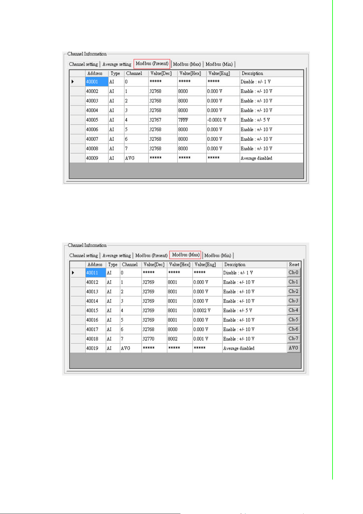
The Modbus (Present) Tab
This tab shows the current analog input values decimal, hex, and engineering units
for all related Modbus addresses.
Chapter 6 System Configuration Guide
The Modbus (Max) Tab
The ADAM-6015, ADAM-6017, and ADAM-6018 feature a historical maximum value
log. You can view the historical maximum analog input values in decimal, hex, and
engineering unit for all related Modbus address. To re-initialize the log, click the corresponding channel buttons in the Reset column.
69 ADAM-6000 User Manual
Page 82

The Modbus (Min) Tab
The ADAM-6015, ADAM-6017, and ADAM-6018 feature a historical minimum value
log. You can view historical minimum analog input values in decimal, hex, and engineering units for all related Modbus addresses. To re-initialize the log, click the corresponding channel buttons in the Reset column.
6.4.2 Individual Channel Configuration
You can view the analog input value and configure the settings for each channel by
clicking on one of the individual channel configuration items (note that the average
you set in the Average setting tab will also be displayed here). The upper part of the
Status Display Area will show the current analog input value and the defined range
for the selected channel, as shown in Figure 6.8.
Figure 6.8 Analog Input Alarm Mode Configuration
ADAM-6000 User Manual 70
Page 83

For the ADAM-6015, ADAM-6017, and ADAM-6018, this screen allows you to configure the built-in alarm function. Two tabs for configuring the high and low alarms for
the selected channel are at the lower part of the Status Display Area.
For both the high and low alarms, you can select one of three alarm modes from the
Alarm mode box:
Disable: The alarm is disabled, meaning that when the alarm condition occurs,
nothing will happen.
Latch: Once the alarm condition occurs, the alarm status will be set to logic high
and the Alarm status LED will continuously be lit; these will remain until the
alarm is cleared manually. For the ADAM-6017 and ADAM-6018, the output
channel specified in the DO mapping panel will continuously generate logic
high value. Click Clear latch to clear the alarm.
Momentary: The alarm status will change dynamically depending on whether
the alarm condition occurs. If the alarm condition occurs, the alarm status will be
logic high; when the alarm condition disappears, the alarm status will change to
logic low. Under this option, the Alarm status LED and the digital output chan-
nel will change according to the alarm condition.
After you choose the alarm mode, click Apply mode to apply the changes.
You can then define the high or low alarm value by entering the value in the Alarm
limit box and then clicking Apply limit. When the analog input value is more than the
high alarm value or less than the low alarm value, the alarm condition will be met and
the alarm status will then be set to logic high. For the ADAM-6015, ADAM-6017, and
ADAM-6018, the alarm status will be shown by the Alarm status LED. Finally, to
map the alarm to a specific a digital output channel, select the channel of interest
from the Channel box and then click Apply.
Chapter 6 System Configuration Guide
6.5 Universal I/O Modules (ADAM-6024)
6.5.1 All-Channel Configuration
The ADAM-6024 features analog I/O and digital I/O channels. Click the all-channel
configuration item in the Module Tree Display Area and there will be two tabs in the
Status Display Area: the Input tab and the Output tab. On the Input tab, there are
four main areas of importance in the Status Display Area, similar to the pages for the
ADAM-6015, ADAM-6017, and ADAM-6018. All the configurations in the Input
Range, Integration Time, and Calibration panels are the same as those for these
three modules. However, unlike these modules, the ADAM-6024 does not feature
averaging, max., and min. functions. Thus, the Channel Information panel for the
ADAM-6024 contains only two tabs: the Channel setting tab and the Modbus
(Present) tab.
71 ADAM-6000 User Manual
Page 84

Figure 6.9 ADAM-6015 Channel Configuration
The Input Tab
This tab shows the current values of the analog input channels. Select the analog
input channels you want to monitor by checking the box in the Enable column and
then click Apply. If the analog input value is out of the input range, you will see
"Over(L)" in the box for the corresponding channel. At the right side, you can see the
current digital input value by DI 0 and DI 1 LED display. You also can view the graphical historical trend of analog input channel by clicking the Trend Log button. All the
operations for trend logging are the same as those for the ADAM-6015, ADAM-6017,
and ADAM-6018.
The Output Tab
This tab shows the current analog input values in decimal and hex format for all
related Modbus address. From the Output tab, you can set the value of an analog or
digital output channel as well as configure all related settings.
Figure 6.10 ADAM-6024 Output Tab
ADAM-6000 User Manual 72
Page 85

6.6 Universal Digital I/O Modules (ADAM-6050,
ADAM-6051- ADAM-6052, ADAM-6060, ADAM-
6066)
6.6.1 All-Channel Configuration
When you click the all-channel configuration item in the Module Tree Display Area,
two tabs will be visible in the Status Display Area: the Channel setting tab and the
Modbus tab. In the following text, the ADAM-6050 is used as an example.
The Channel Setting Tab
Chapter 6 System Configuration Guide
From this tab, you can view the status of all digital input channels from the LED
beside each channel button. You can also control the statuses of all digital output
channels by clicking the corresponding button.
Fail-Safe Value Configuration
When communication between the host PC and an ADAM-6000 digital module is broken, the digital output channels can generate a predefined value, which is referred to
as a fail-safe value (FSV).
If the FSV box beside a channel is checked, it means that the module will set that
output channel to logic high when a WDT timeout occurs. There are two applications
for this. After all changes have been made, click Apply FSV for the changes to take
effect.
Communication WDT
When the module has not received any TCP network packet from the client in some
time, the module will automatically set the FSV to output if the waiting time is greater
than the host idle time.
73 ADAM-6000 User Manual
Page 86

P2P/GCL WDT
When the module has not received P2P/GCL network packets in some time, this
means that the waiting time is greater than the idle time you have entered; the module will automatically send the FSV to the host PC if you have enabled this function.
The Modbus Tab
From this tab, you can view current digital I/O output values for all related Modbus
addresses.
6.6.2 Individual Channel Configuration
To view the values and configure the settings of digital I/O channels, simply click the
channel of interest in the list of individual channel configuration items.
ADAM-6000 User Manual 74
Page 87

Digital Input Mode
If you choose a digital input channel from the list of individual channel configuration
items, the Status Display Area will appear as shown in Figure 6.11.
Chapter 6 System Configuration Guide
Figure 6.11 Digital Input Modes
You can choose different input modes for the selected digital input channel from the
DI mode box (the option you select will depend on the hardware specification). After
you have selected the mode, click Apply mode to save the changes. The five modes
you can choose from are detailed in the following text.
DI Mode: DI
In this mode, you can see the digital input value by clicking the DI status LED.
Some digital modules support an invert digital input status function. When you enable
this function, the module will automatically inverse the digital input value. For example, if the actual external signal value is logic low, then the DI status LED will be lit
75 ADAM-6000 User Manual
Page 88

(normally, it is lit only when the signal is logic high). If your module supports this function, an Invert signal box will be visible in the Setting panel. Simply select/clear this
box to enable/disable this function and then click Apply to all (for all channels) or
Apply (for the selected channel) to complete the configuration.
All ADAM-6000 digital modules support a digital filter for removing high- and low-frequency noise. You can enable/disable the filter by selecting/clearing the Enable digi-
tal filter box. When the filter is enabled, you can define the minimum and maximum
acceptable signal width from the Minimum low signal width and Minimum high
signal width boxes (unit: ms). Remember to click Apply to all (for all channels) or
Apply (for the selected channel) to complete the configuration.
DI Mode: Counter
A counter counts the number of pulse numbers of a digital signal from the selected
channel and then records that in a register. When Counter is selected from the DI
mode box, the Status Display Area will appear similar to when DI is selected. Under
this mode, the current count value of the selected channel will be displayed in the
Counter value box. You can start or stop the counter by clicking Start/Stop next to
the Counter value box, and you can also reset the counter (the value in the register
will also be initialized to zero) by clicking Clear.
Similar to when DI is selected from the DI mode box, you can enable/disable the
invert digital input status function and digital filter in the Setting panel. One additional
setting, however, is that you can define whether the counter should keep the last
value when the module is powered off; when the module is powered on again, the
counter will continue counting from that stored value. Otherwise, the counter will be
reset to zero when the module is powered on. You can enable/disable this function by
selecting/clearing the Keep last value when power off box and then clicking Apply
to all (for all channels) or Apply this (for the selected channel) to complete the configuration.
ADAM-6000 User Manual 76
Page 89

DI Mode: Low-to-High Latch
Low-to-high latch mode means that once the digital input channel detects a logic
level change from low to high, the logic status will remain logic high until you clear
latch manually, which will return the logic status to logic low. The logic status can be
seen by the Latch status LED. The latch can be cleared by clicking Clear latch. This
mode also supports the invert digital input status function, which can be enabled/disabled by checking/clearing the Invert signal box and then clicking Apply to all (for
all channels) or Apply this (for the selected channel) to complete the configuration.
Chapter 6 System Configuration Guide
DI Mode: High-to-Low Latch
High-to-low latch mode means that once the digital input channel detects a logic level
change from high to low, the logic status will remain as logic high until you clear latch
manually, which will return the logic status to logic low. The logic status can be seen
by the Latch status LED. The latch can be cleared by clicking Clear latch. This
mode also supports the invert digital input status function, which can be enabled/dis-
77 ADAM-6000 User Manual
Page 90

abled by selecting/clearing the Invert signal box and then clicking Apply to all (for
all channels) or Apply this (for the selected channel) to complete the configuration.
DI Mode: Frequency
When Frequency is selected from the DI mode box, the module will calculate the
frequency of the digital input signal for the selected channel. This value will be displayed in the Frequency value box.
Digital Output Mode
If you choose a digital output channel from the list of individual channel configuration
items, the Status Display Area will appear as shown in Figure 6.12.
Figure 6.12 Digital Output Modes
ADAM-6000 User Manual 78
Page 91

You can choose different output modes for the selected digital output channel from
the DO mode box (the option you select will depend on the hardware specifications).
After you have selected the mode, click Apply mode to save the changes. There four
modes you can choose from, as detailed in the following text.
DO Mode: DO
Chapter 6 System Configuration Guide
This mode allows you to control the digital output value of the selected channel,
which can be adjusted by clicking DO. The current digital output value will be shown
by the DO status LED.
DO Mode: Pulse Output
When Pulse output is selected from the DI mode box, the selected digital output
channel will generate a continuous pulse train or a finite number of pulses. You can
define the pulse width in the Low signal width and High signal width boxes in the
79 ADAM-6000 User Manual
Page 92
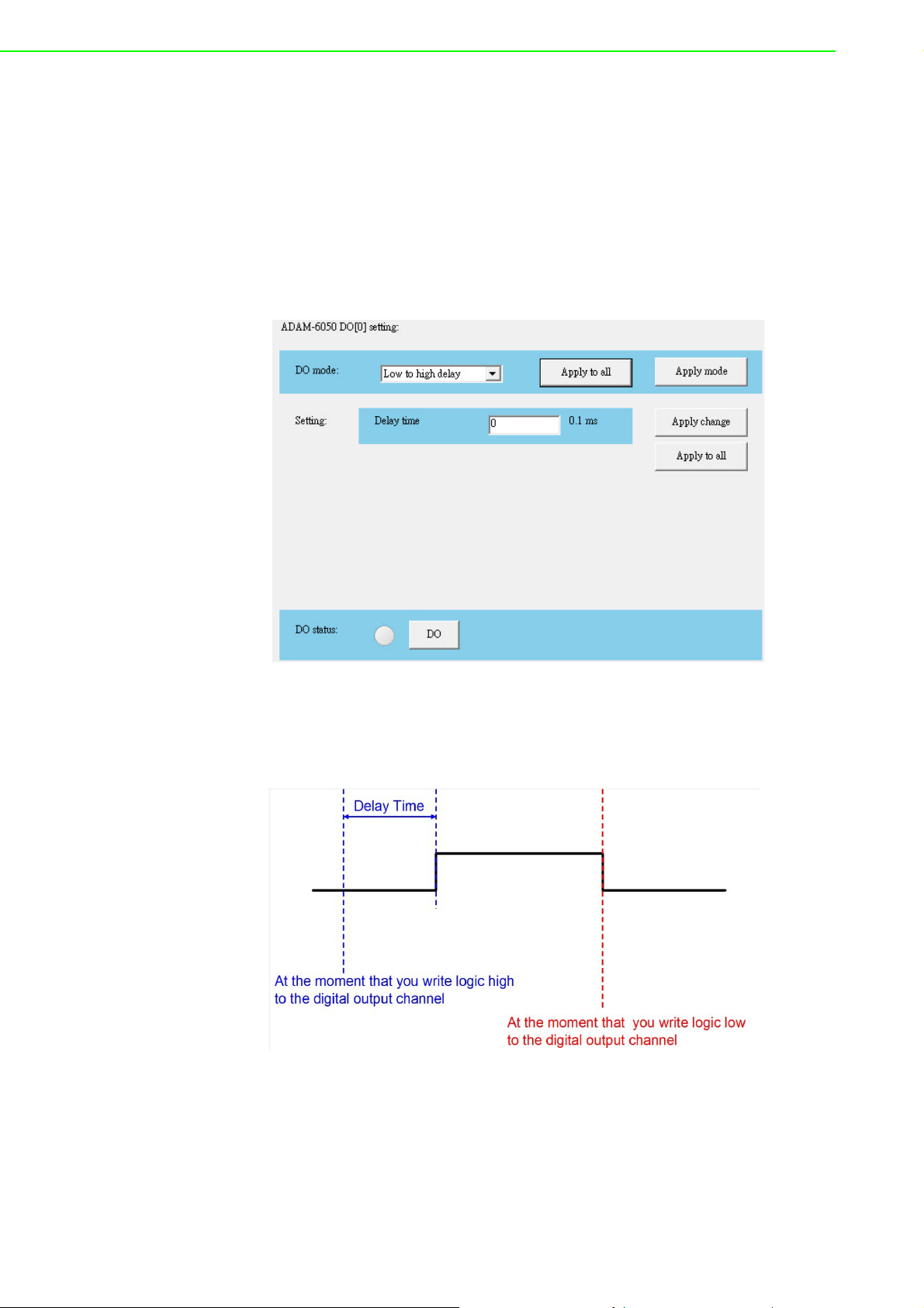
Setting panel (unit: 0.1 ms). The frequency and duty cycle of the pulse output signal
will be calculated automatically and displayed in the Output frequency and Duty
cycle boxes. After you have completed the settings, click Apply mode (for individual
channels) or Apply to all (for all channels). You can then choose to generate a continuous pulse train or finite number of pulses by selecting Continue (for a pulse train)
or Fixed total (for a finite number of pulses). When you selected Fixed total, you will
need to enter how many pulses you want to generate. After the pulse output mode
has been selected, click Start/Stop to generate/stop the pulse output.
DO Mode: Low-to-High Delay
When you choose Low to high delay from the DI mode box, it is the same as selecting DO except that there will be a delay before the output value changes from logic
low to logic high, as depicted in Figure 6.13.
Figure 6.13 Graph Explaining Low to High Delay Output Mode
To define the delay time, simply enter the value in the Delay time box and then click
Apply to complete the configuration. You can then control the digital output value by
clicking DO and you can determine its current value from the DO status LED.
ADAM-6000 User Manual 80
Page 93
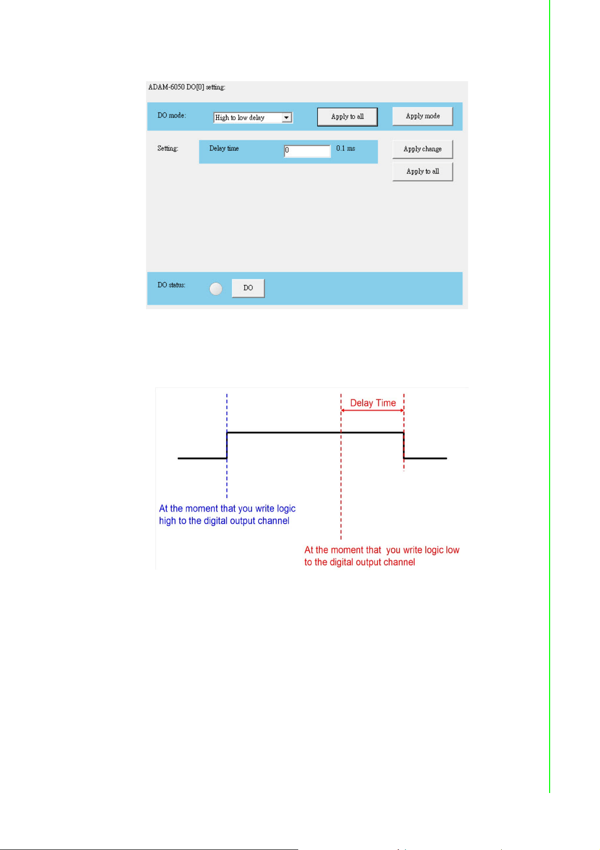
DO Mode: High-to-Low Delay
When you choose High to low delay from the DI mode box, it is the same as select-
ing DO except that there will be a delay before the output value changes from logic
high to logic low, as depicted in Figure 6.14.
Chapter 6 System Configuration Guide
Figure 6.14 Graph Explaining Low to High Delay Output Mode
To define the delay time, simply enter the value in the Delay time box and then click
Apply to complete the configuration. You can then control the digital output value by
clicking DO and you can determine its current value from the DO status LED.
6.7 Introduction to P2P Functions
When you want to send a signal from one module to another module, P2P is the ideal
solution. With the P2P function enabled, ADAM-6000 modules can actively update
their input values to other devices such as PCs or other ADAM-6000 modules. A typical application is using a pair of ADAM-6000 modules, in which the value of an input
channel on one module will be automatically updated to output channel on another
module. The data will be transferred automatically as long as the connection between
the two ADAM-6000 modules is already established, and no controller is needed to
81 ADAM-6000 User Manual
Page 94

handle the communication.
Note! 1. Please use an Ethernet switch between a pair of P2P modules (do not
use an Ethernet hub) in order to prevent data packet collisions.
2. ADAM-6000 modules support two functions: P2P (Event) and GCL
(see Chapter 8). You cannot enable both of these two features at the
same time. Thus, if GCL is enabled and want to use P2P, you will need
to disable GCL first (see Section 8.2 for instructions on how to disable
GCL).
3. To utilize the P2P function, you will need to upgrade the firmware version of your ADAM-6000 module to 3.x or later.
6.7.1 P2P Communication Modes
All ADAM-6000 modules feature two types of P2P function: 1) basic mode and 2)
advanced mode.
Basic Mode
For basic mode, there will be only one target device (Module B) receiving data from
the source module (Module A). Usually, Module B is another ADAM-6000 module.
The input channels of Module A will be mapped to the output channels of Module B,
so that the values of all Module A inputs channels are automatically updated to the
Module B outputs. You can also define a mask to disconnect a relationship between
some inputs and outputs.
Figure 6.15 Basic Mode for P2P
Advanced Mode
For advanced mode, there will be multiple target devices (Module B, Module C, etc.)
receiving data from the source module (Module A). You can define different target
devices by assigning different IP address to each channel of Module A. For example,
you can map Input Channel 1 of Module A to Output Channel 3 of Module B, while
Input Channel 2 of Module A is mapped to Output Channel 4 of Module C. Refer to
Figure 6.16.
ADAM-6000 User Manual 82
Page 95

Chapter 6 System Configuration Guide
Figure 6.16 Advanced mode for P2P
6.7.2 P2P Communication Methods
As for when the data will be updated from a source module to the target devices,
there are two options to choose from: 1) period time and 2) period time + change-ofstatus (COS).
Period Time
With this function, the value of the input channel will be updated to the target devices
at the defined period.
Period Time + COS
This option still causes the value of the input channel to be updated to the target
devices at the defined period, but when a COS occurs (i.e., a change in the analog
input value greater than a specified deviation or a digital input status change), the
value of the input channel will immediately update to the target devices.
6.7.3 P2P Event Triggers
In many applications, data will only be sent to a host computer when a specific event
occurs, such as when a digital or analog signal changes. In this type of application,
the P2P function is ideal. The target P2P device can be a computer, for which you
would simply need to enter its IP address and select basic mode as the communication mode and period time + COS as the communication method.
There should be one program running on the host computer to receive the data, and
we provide an example C program (VC++ 6.0) on the companion CD. Although
ADAM-6000 modules will send data to the host computer periodically (for the sake of
communication security), you can still distinguish whether messages have been sent
via the period time or COS function. The message contains information on which
channels have changed. Thus, if the message indicates no change in all channels,
then no event has occurred.
83 ADAM-6000 User Manual
Page 96

Note! There is invariably some level of uncertainty in network communication.
Sometimes, there may be packet loss when an event occurs. This is
why we provide the period time + COS function (no COS function
alone). When an event occurs, even if a packet is lost, the data will be
sent again at the next period. This improves system reliability.
6.8 How to Configure P2P Functions
Select the IP address of an ADAM-6000 module from the Module Tree Display Area
and click the Peer to Peer/Event tab. The screen will appear as shown in Figure
6.17.
Figure 6.17 Peer to Peer/Event Tab
By default, the P2P function is disabled. You can enable it by selecting Basic or
Advanced in the Mode panel and then clicking Apply. ADAM-6000 modules support
both P2P and GCL functionality (see Chapter 8 for information on GCL); however,
only one of them can be enabled at one time. If GCL is already enabled and you
choose to enable P2P, an alert will appear asking you to first disable GCL (see Section 8.2 for how to disable GCL). After GCL has been disabled, you can then select
Basic or Advanced to enable P2P.
ADAM-6000 User Manual 84
Page 97

6.8.1 Basic Mode Configuration
In basic mode, the Status Display Area will appear as shown in Figure 6.18. You can
define the target device by entering its IP address in the Destination box in the
Basic (One to One) panel.
Chapter 6 System Configuration Guide
Figure 6.18 P2P Basic Mode Configuration
Note that when you select basic mode, the default communication method is period
time; to select period time + COS, you will need to select the Deviation Enable
(C.O.S) box (for analog modules; not shown in this example) or the Enable Change
of State box (for digital modules). If you do not select this box, the communication
method will be period time.
The period to transfer data from the source module to the destination module can be
set in the Period time box in the Basic (One to One) panel. You can define the deviation for analog input by the Deviation Rate numeric control (the value is a percentage and represents the change value divided by the total range).
By default, all input channels of the source module will all be mapped to all output
channels of the destination module. However, you can manually define which channels are mapped by clicking the Modify channel enable box. This will allow you to
choose which input channels to map to the corresponding output channels by selecting the channel in the Enable column and then clicking Apply list. In Figure 6.18, the
values of Input Channels 0~3 of the source module will update to Output Channels
0~3 of the destination module. You can save the current mapping relation into a configuration file by clicking Save. You can also load a mapping configuration file by
clicking Load. Click Refresh will show the current mapping configuration on the
source module in the table.
85 ADAM-6000 User Manual
Page 98

6.8.2 Advanced Mode Configuration
In advanced mode, the Status Display Area will appear as shown in Figure 6.19. The
mapping relationship is configured using controls in the Source and Destination
panels.
Figure 6.19 P2P Advanced Mode Configuration
Follow these steps to define the mapping relationship:
1. Select the input channel from the Channel box in the Source panel
2. Use Period time, the Deviation enable (C.O.S) box (for analog modules) or
Change of State (C.O.S) box (for digital modules), and Deviation Rate in the
Source panel to define when to transfer the data for that channel
3. Enter the IP address of the target module in the IP box in the Destination panel
4. Select the name of the target module from the Name box
5. From the Channel box, select the output channel on the target module that will
receive the data
6. Click Config to list
Once you have completed these steps, the configuration for that channel will be displayed in the mapping table at the bottom of the Advanced (One to Multi) panel.
You will need to repeat Steps 1~4 for each input channel you wish to map. Once you
have configured all the input channels, click Apply list to download the mapping configuration to the target module. You can save all configurations in the mapping table
to a file by clicking Save. You can also load a previous configuration file by clicking
Load. Clicking Refresh will show the current configuration of the source module in
the mapping table.
Note! It is suggested that you to download all channels mapping configuration
together at one time instead of downloading one-channel setting many
times. The reason is that this can reduce the number of times the flash
memory on target module is used, thus helping to extend the flash memory life.
ADAM-6000 User Manual 86
Page 99

To save time, you can copy one channel configuration to other channels and then
make final adjustments to each channel. To do this, click Copy To, which will open
the window shown in Figure 6.20.
Chapter 6 System Configuration Guide
Figure 6.20 Copy One Setting to Other Channels
Here, you will need to choose the channel you wish to copy from the Channel box
and then select the channels you want to copy the settings to by selecting them from
the Channel column in the Copy to panel and then clicking Config (check Select all
to copy to all channels). In this example, the settings of Channel 0 will be copied to
Channels 0, 2, 3, and 4.
When you return to the Peer to Peer/Event tab, you will find that the settings of the
channels you selected now appear in the mapping table. You can the select the individual channels you need to modify and change the parameters.
P2P Data Transfer Performance
Wired LAN Module
Condition: transfer data from one channel of an ADAM-6050 module to one channel
of another ADAM-6050 module, via one Ethernet switch.
Data Transfer Time: <1.2 ms
6.9 ADAM-6000 Web Server
ADAM-6000 modules all feature a built-in web server that can be accessed using a
standard web browser. The web service allows programmers to create powerful customized web pages by using web programming languages. Remote computers or
devices can thus be used to monitor and control the I/O status of ADAM-6000 modules remotely via a web browser. ADAM-6000 modules come with a default built-in
web page that you can modify using HTML5 or a Java Applet.
87 ADAM-6000 User Manual
Page 100

The default HTML settings on ADAM-6000 modules do not support HTML5; for
HTML5 support, you will need to download a new file from the Advantech website. If
you use a Java Applet to modify your module, you will need to install Java Virtual
Machine to browse the web page. Additional instructions for Java Applet implementation can be found in Section 6.9.2.
To access the web server, simply type the IP address into your browser to connect to
your ADAM-6000 module. You will be prompted to enter a user name (default: root)
and password (default: 00000000). After you have entered the correct password, you
can start monitoring/controlling the I/O channels on your ADAM-6000 module.
6.9.1 HTML 5
HTML 5 Introduction
HTML is the most widely used language in web content design. The latest version,
HTML 5, enhances the syntax structure and incorporates multiple web technologies
(e.g., CSS and JavaScript), thus allowing for the implementation of additional web
services, APIs, and interactive applications in mobile communications.
Remote Monitoring and Control via the ADAM-6000 Web Server
This new feature will bring obvious benefits in terms of being able to perform field
maintenance from anywhere over an Ethernet network. This section describes how
to connect and configure your system and devices to perform remote monitoring and
control, including from a PC, laptop, and portable devices such as a smartphone or
pad.
Preset conditions:
1. Complete the installation and network configuration of your ADAM-6000 module
2. Ensure that your ADAM-6000 module is connected to your local Ethernet net-
work
Note! ADAM-6000 modules are developed by public HTML 5 base, but for detailed
indication and data transmission mode may be different on the web page of the operating system. The minimum browser requirements are as follows:
Smartphone Browser Requirements
Safari 5 for Apple iOS
Web Browser for Google Android 4.0 (Ice Cream Sandwich)
Chrome for Google Android 4.0 (Ice Cream Sandwich)
PC Browser Requirements
Internet Explorer (Version 9)
Google Chrome (Version 8)
Mozilla Firefox (Version 10)
ADAM-6000 User Manual 88
 Loading...