

Page 1

User Manual
ADAM-5630 Series
Page 2

Copyright
The documentation and software included with this product are copyrighted 2020 by
Advantech Co., Ltd. All rights are reserved. Advantech Co., Ltd. reserves the right to
make improvements in the products described in this manual at any time without
notice. No part of this manual may be reproduced, copied, translated, or transmitted
in any form or by any means without the prior written permission of Advantech Co.,
Ltd. Information provided in this manual is intended to be accurate and reliable. However, Advantech Co., Ltd. assumes no responsibility for its use, nor for any infringements of the rights of third parties, which may result from its use.
Acknowledgements
Intel® and Pentium® are trademarks of Intel® Corporation.
Microsoft Windows and MS-DOS are registered trademarks of Microsoft Corp.
All other product names or trademarks are properties of their respective owners.
Product Warranty (2 years)
Advantech warrants to you, the original purchaser, that each of its products will be
free from defects in materials and workmanship for two years from the date of purchase.
This warranty does not apply to any products which have been repaired or altered by
persons other than repair personnel authorized by Advantech, or which have been
subject to misuse, abuse, accident or improper installation. Advantech assumes no
liability under the terms of this warranty as a consequence of such events.
Because of Advantech’s high quality-control standards and rigorous testing, most of
our customers never need to use our repair service. If an Advantech product is defective, it will be repaired or replaced at no charge during the warranty period. For outof-warranty repairs, you will be billed according to the cost of replacement materials,
service time and freight. Please consult your dealer for more details.
If you think you have a defective product, follow these steps:
1. Collect all the information about the problem encountered. (For example, CPU
speed, Advantech products used, other hardware and software used, etc.) Note
anything abnormal and list any on screen messages you get when the problem
occurs.
2. Call your dealer and describe the problem. Please have your manual, product,
and any helpful information readily available.
3. If your product is diagnosed as defective, obtain an RMA (return merchandise
authorization) number from your dealer. This allows us to process your return
more quickly.
4. Carefully pack the defective product, a fully-completed Repair and Replacement
Order Card and a photocopy proof of purchase date (such as your sales receipt)
in a shippable container. A product returned without proof of the purchase date
is not eligible for warranty service.
5. Write the RMA number visibly on the outside of the package and ship it prepaid
to your dealer.
Part No. 2003563000 Edition 1
Printed in Taiwan May 2020
ADAM-5630 Series User Manual ii
Page 3

Declaration of Conformity
CE
This product has passed the CE test for environmental specifications when shielded
cables are used for external wiring. We recommend the use of shielded cables. This
kind of cable is available from Advantech. Please contact your local supplier for
ordering information.
FCC Class A
Note: This equipment has been tested and found to comply with the limits for a Class
A digital device, pursuant to part 15 of the FCC Rules. These limits are designed to
provide reasonable protection against harmful interference when the equipment is
operated in a commercial environment. This equipment generates, uses, and can
radiate radio frequency energy and, if not installed and used in accordance with the
instruction manual, may cause harmful interference to radio communications. Operation of this equipment in a residential area is likely to cause harmful interference in
which case the user will be required to correct the interference at his own expense.
Technical Support and Assistance
1. Visit the Advantech website at www.advantech.com/support where you can find
the latest information about the product.
2. Contact your distributor, sales representative, or Advantech's customer service
center for technical support if you need additional assistance. Please have the
following information ready before you call:
– Product name and serial number
– Description of your peripheral attachments
– Description of your software (operating system, version, application software,
etc.)
– A complete description of the problem
– The exact wording of any error messages
Warnings, Cautions, and Notes
Warning! Warnings indicate conditions, which if not observed, can cause personal
injury!
Caution! Cautions are included to help you avoid damaging hardware or losing
data. e.g.
There is a danger of a new battery exploding if it is incorrectly installed.
Do not attempt to recharge, force open, or heat the battery. Replace the
battery only with the same or equivalent type recommended by the manufacturer. Discard used batteries according to the manufacturer's
instructions.
iii ADAM-5630 Series User Manual
Page 4

Note! Notes provide optional additional information.
Packing List
The accessory package of ADAM-5630 series contains the following items:
(A) ADAM-5630 series
(B) 1 x warranty card
Safety Instructions
1. Read these safety instructions carefully.
2. Keep this user manual for future reference.
3. Disconnect this equipment from any AC outlet before cleaning. Use a damp
cloth. Do not use liquid or spray detergents for cleaning.
4. For plug-in equipment, the power outlet socket must be located near the equip-
ment and must be easily accessible.
5. Keep this equipment away from humidity.
6. Put this equipment on a reliable surface during installation. Dropping it or letting
it fall may cause damage.
7. The openings on the enclosure are for air convection. Protect the equipment
from overheating. DO NOT COVER THE OPENINGS.
8. Make sure the voltage of the power source is correct before connecting the
equipment to the power outlet.
9. Position the power cord so that people cannot step on it. Do not place anything
over the power cord.
10. All cautions and warnings on the equipment should be noted.
11. If the equipment is not used for a long time, disconnect it from the power source
to avoid damage by transient over-voltage.
12. Never pour any liquid into an opening. This may cause fire or electrical shock.
13. Never open the equipment. For safety reasons, the equipment should be
opened only by qualified service personnel.
14. If one of the following situations arises, get the equipment checked by service
personnel:
The power cord or plug is damaged.
Liquid has penetrated into the equipment.
The equipment has been exposed to moisture.
The equipment does not work well, or you cannot get it to work according to the
user manual.
The equipment has been dropped and damaged.
The equipment has obvious signs of breakage.
15. DO NOT LEAVE THIS EQUIPMENT IN AN ENVIRONMENT WHERE THE
STORAGE TEMPERATURE MAY GO BELOW -25 °C (-13 °F) OR ABOVE 70
°C (158 °F). THIS COULD DAMAGE THE EQUIPMENT. THE EQUIPMENT
SHOULD BE IN A CONTROLLED ENVIRONMENT.
16. CAUTION: DANGER OF EXPLOSION IF BATTERY IS INCORRECTLY
REPLACED. REPLACE ONLY WITH THE SAME OR EQUIVALENT TYPE
RECOMMENDED BY THE MANUFACTURER, DISCARD USED BATTERIES
ACCORDING TO THE MANUFACTURER'S INSTRUCTIONS.
ADAM-5630 Series User Manual iv
Page 5

17. Due to the sensitive nature of the equipment it must be stored in a restricted
access location, only accessible by qualified engineers.
18. When installing this equipment, ensure that the grounding cable is securely
attached using a 3.5 mm (0.13 in) screw.
19. This equipment does not include a power cord and plug. The sound pressure
level at the operator's position according to IEC 704-1:1982 is no more than 70
dB (A).
DISCLAIMER: This set of instructions is given according to IEC 704-1. Advantech
disclaims all responsibility for the accuracy of any statements contained herein.
Safety Precaution - Static Electricity
Follow these simple precautions to protect yourself from harm and the products from
damage.
To avoid electric shock, always disconnect the power from your PC chassis
before you work on it. Don't touch any components on the CPU card or other
cards while the PC is on.
Disconnect power before making any configuration changes. The sudden rush
of power as you connect a jumper or install a card may damage sensitive electronic components.
v ADAM-5630 Series User Manual
Page 6

ADAM-5630 Series User Manual vi
Page 7

Contents
Chapter 1 Introduction..........................................1
1.1 Product Concepts and Positioning ............................................................ 2
Table 1.1: Supported I/O Module List.......................................... 2
1.2 Hardware Specifications ........................................................................... 3
1.2.1 General ......................................................................................... 3
1.2.2 System Hardware ......................................................................... 3
1.2.3 System Software........................................................................... 3
1.2.4 I/O Interface .................................................................................. 3
1.2.5 Environment.................................................................................. 3
1.3 Safety Precautions .................................................................................... 4
1.4 Chassis Dimensions.................................................................................. 5
Figure 1.1 ADAM-5630E chassis dimensions ............................. 5
Figure 1.2 ADAM-5630 chassis dimensions................................ 5
Chapter 2 Overview...............................................7
2.1 Overview ................................................................................................... 8
Figure 2.1 ADAM-5630E overview (I/O modules are optional and
not included) ............................................................... 8
2.2 LED Status Indicator ................................................................................. 8
Figure 2.2 ADAM-5630 series LED status indicator .................... 8
2.2.1 System Status Indicator ................................................................ 9
Chapter 3 Wiring and Installation ......................11
3.1 Wiring ...................................................................................................... 12
3.1.1 Power Supply Wiring................................................................... 12
Figure 3.1 Power supply wiring.................................................. 12
Table 3.1: DC Power Input Connector Pin Definition ................ 12
3.1.2 Communication Ports.................................................................. 12
Table 3.2: Debug Port Pin Definitions ....................................... 13
Table 3.3: USB Connector Pin Assignment............................... 14
Table 3.4: Definition of LAN Status Indicators ........................... 14
Table 3.5: VGA Adapter Cable Pin Assignments ...................... 14
Table 3.6: Node ID Setting ........................................................ 15
3.2 Jumper Setting ........................................................................................ 16
3.2.1 Jumper Setting............................................................................ 16
Figure 3.2 The location of jumper CN2 on the power board...... 16
Table 3.7: Jumper Setting for COM1 ......................................... 16
Figure 3.3 The location of jumper CN3 on the power board...... 17
Table 3.8: Jumper Setting for COM2, 3 ..................................... 17
Figure 3.4 The location of jumper CN4 on the power board...... 18
Table 3.9: Jumper Setting for COM4 ......................................... 18
3.3 Installation ............................................................................................... 19
3.3.1 System mounting ........................................................................ 19
Figure 3.5 DIN-rail mounted installation (8 slots as example) ... 19
Figure 3.6 Wall mounted installation (8 slots as example) ........ 19
3.3.2 SD Card Installation .................................................................... 20
Figure 3.7 SD Card installation.................................................. 20
3.3.3 Change RTC Battery................................................................... 20
Figure 3.8 Battery replacement ................................................. 20
i ADAM-5630 Series User Manual
Page 8

ADAM-5630 Series User Manual ii
Page 9

Chapter 1
1 Introduction
Page 10

1.1 Product Concepts and Positioning
ADAM-5630 is a RISC architecture platform adaptable to broad temperature ranges
and featuring a flexible design. This high performance device serves as an intelligent
Edge DAQ platform for connecting multi-field site devices and remote monitoring
centers via industry standard protocols. ADAM-5630 supports 4/8 I/O slots for monitoring and control.
To set up an ADAM-5630 series controller, you need to select I/O modules that interface with predetermined field devices and programs. Advantech provides different
types of ADAM-5000 I/O modules for various applications. The following table details
these I/O modules:
Table 1.1: Supported I/O Module List
Module Name Specification
ADAM-5013 3-Ch RTD input
ADAM-5017 8-Ch AI
ADAM-5017P 8-Ch AI with independent Input
Analog I/O
USB/Storage Extension ADAM-5030 2 USB ports and 2 SD slots
Digital I/O
Relay Output
Counter/Frequency
Serial I/O ADAM-5091 4-port RS232/422/485 with Isolated
CAN I/O ADAM-5095 2-port CAN Uni-PCI COMM Module w/I
Extension
ADAM-5017H 8-Ch High-speed AI
ADAM-5017UH 8-Ch Ultra high speed AI
ADAM-5018 7-Ch Thermocouple input
ADAM-5018P 7-Ch Thermocouple input with independent Input
ADAM-5024 4-Ch AO
ADAM-5050 16-Ch DI/O
ADAM-5051 16-Ch DI
ADAM-5051D 16-Ch DI w/LED
ADAM-5051S 16-Ch Isolated DI w/LED
ADAM-5052 8-Ch DI
ADAM-5053S 32-Ch Isolated DI (TTL)
ADAM-5055S 16-Ch. Isolated DI/O w/LED
ADAM-5056 16-Ch DO
ADAM-5056D 16-Ch DO w/LED
ADAM-5056S 16-Ch Isolated DO w/LED
ADAM-5056SO 16-Ch Iso. DO w/LED (source)
ADAM-5057S 32-Ch Isolated DO (TTL)
ADAM-5060 6-Ch. Relay output
ADAM-5069 8-Ch Power Relay output w/ LED
ADAM-5080 4-Ch Counter/Frequency
ADAM-5081 4-Ch High Speed Counter/Frequency
ADAM-5101 m-SATA/m.2 Storage Extension
ADAM-5101P Mini PCIE Slot Extension
ADAM-5192 2-Ch USB to LAN
ADAM-5630 Series User Manual 2
Page 11

1.2 Hardware Specifications
1.2.1 General
Certification: CE, FCC
Dimensions (W x D x H):
– 4 slots: 231 x 75 x 110 mm (9.09 x 2.95 x 4.33 in)
– 8 slots: 355 x 75 x 110 mm (13.9 x 2.95 x 4.33 in)
Enclosure: ABS +PC
Mounting: DIN-Rain, Wall-Mount
Power Consumption: 8W (Typical, no added on card)
Power Requirements: 10~30 V
System Design: Fanless with no internal cabling
OS Support: Real time Linux
1.2.2 System Hardware
CPU: TI Cortex A8, 600MHz
Memory: RAM DDR3L 512MB
Battery memory: 128KB
Indicators: LEDs for Power, LAN (LINK, ACT), BAT, ERR, Programmable (LED1
~ LED4)
Storage: 1GB NAND
SD Slot: 1 x Micro-SD slot
Display: DB15 VGA connector, 800x600 @ 60 Hz
Watchdog Timer: YES
Node ID: 8-bit
DC
Chapter 1 Introduction
1.2.3 System Software
OS Support: RT-Linux 3.12 above (Distributor: Yocto)
Configuration Tool: web, Command Terminal
Protocol Support: Modbus/TCP, Modbus/RTU
Programming: Linux C, Python, KW
1.2.4 I/O Interface
Serial Ports:
– COM1: RS-232/485 (Screw terminal) Isolation 2500 V
– COM2: RS-485 (Screw terminal) Isolation 2500 V
– COM3: RS-485 (Screw terminal) Isolation 2500 V
– COM4: RS-232/485 (DB-9)
Serial Port Speed: RS-232/RS-485: 50 ~ 115.2 kbps
LAN: 2 x 10/100/1000 Base-T RJ-45 ports
USB Ports: 2 x USB, Rev. 2.0 compliant
1.2.5 Environment
Humidity: 5 ~ 95% (non-condensing)
Operating Temperature: -40 ~ 70 °C (-40 ~ 158 °F)
Storage Temperature: -40 ~ 85 °C (-40 ~ 176 °F)
Safety Cert. Temperature:-20 ~ 50 °C (-4 ~ 122 °F)
DC
DC
DC
3 ADAM-5630 Series User Manual
Page 12

Operating Humidity: 20 ~ 95% (non-condensing)
Shock Protection: IEC 60068-2-27
Vibration Protection: IEC 60068-2-64 (Random 1 Oct./min, 1hr/axis.)
1.3 Safety Precautions
The following content details individual connection instructions. In most cases, you
will only need to connect a standard cable.
Warning! Always disconnect the power cord from your chassis whenever you are
working on it. Do not connect while the power is on. A sudden rush of
power can damage sensitive electronic components. Only experienced
electronics personnel should open the chassis.
Caution! Always ground yourself to remove any static electric charge before
touching ADAM-5000 series. Modern electronic devices are very sensitive to static electric charges. Use a grounding wrist strap at all times.
Place all electronic components on a static-dissipative surface or in a
static-shielded bag.
Note! If DC voltage is supplied by an external circuit, please put a protection
device in the power supply input port.
ADAM-5630 Series User Manual 4
Page 13

1.4 Chassis Dimensions
Chapter 1 Introduction
Figure 1.1 ADAM-5630E chassis dimensions
Figure 1.2 ADAM-5630 chassis dimensions
5 ADAM-5630 Series User Manual
Page 14

ADAM-5630 Series User Manual 6
Page 15

Chapter 2
2 Overview
Page 16
2.1 Overview
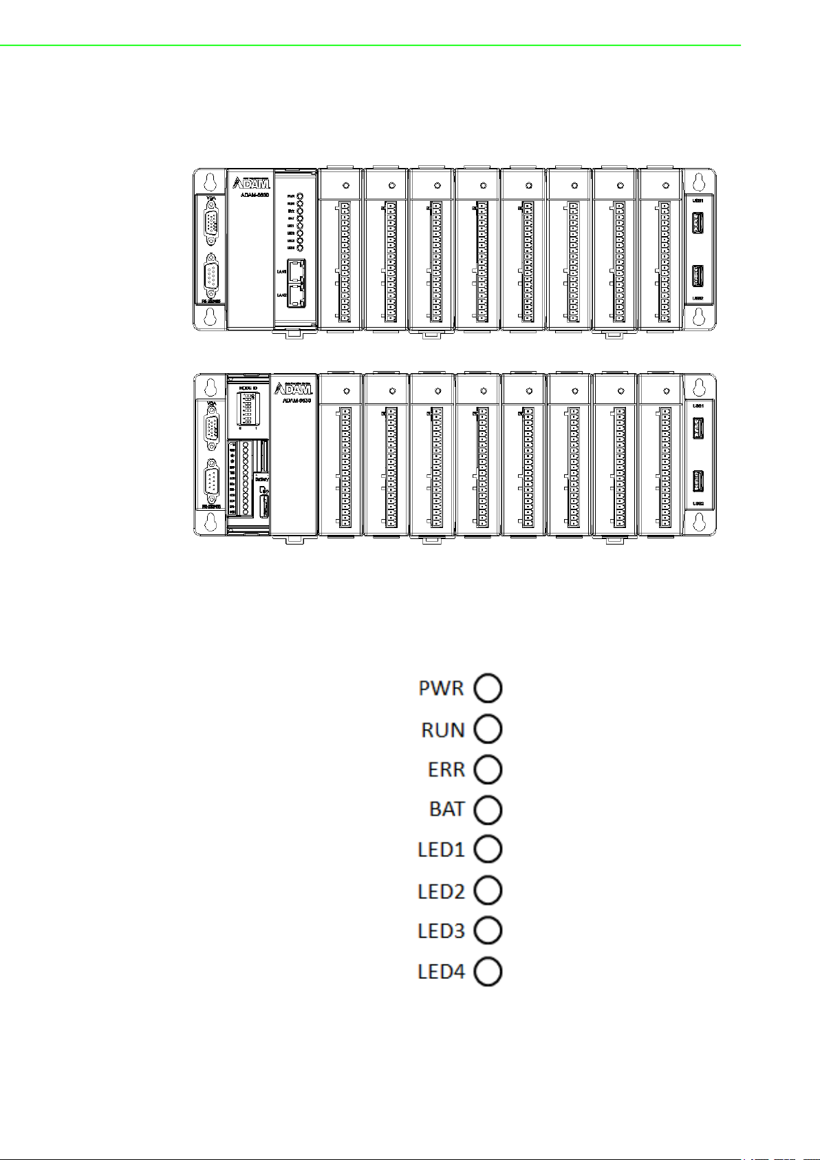
The following diagrams demonstrate the indicators and connectors on ADAM-5630E.
Figure 2.1 ADAM-5630E overview (I/O modules are optional and not included)
2.2 LED Status Indicator
Figure 2.2 ADAM-5630 series LED status indicator
ADAM-5630 Series User Manual 8
Page 17

2.2.1 System Status Indicator
LED Status Description
PWR
RUN
ERR
BAT
LED1~LED4
Green Power is on.
Off Power is off.
Green
Off
Green
Off
On Need to change Battery.
Off Normal.
Green
Off
Chapter 2 Overview
Users can define the Programmable LED state according
to individual needs.
Users can define the Programmable LED state according
to the individual need.
Users can define the Programmable LED state according
to individual need.
9 ADAM-5630 Series User Manual
Page 18

ADAM-5630 Series User Manual 10
Page 19

Chapter 3
3 Wiring and Installation
Page 20

3.1 Wiring
3.1.1 Power Supply Wiring
ADAM-5630 supports power input ranging from 10VDC to 30VDC.
Figure 3.1 Power supply wiring
Table 3.1: DC Power Input Connector Pin Definition
Function Pin Screen Printing Function Description
1 V+ DC power input PIN
Power Input
2 GND DC power input PIN
3 GND
3.1.2 Communication Ports
ADAM-5630 Series User Manual 12
Page 21

3.1.2.1 Terminal Connector
Chapter 3 Wiring and Installation
3.1.2.2 DB-9 COM Ports (COM4)
Table 3.2: Debug Port Pin Definitions
Pins RS-232 RS-485
1 DCD DATA-
2 RXD
3 TXD
4 DTR DATA+
5 GND
6 DSR
7 RTS
8 CTS
9 RI
13 ADAM-5630 Series User Manual
Page 22

3.1.2.3 USB Connector
Table 3.3: USB Connector Pin Assignment
Pin Signal Cable Color
1 VCC Red
2 DATA- White
3 DATA+ Green
4 GND Black
3.1.2.4 LAN Connectors (LAN1~LAN2)
Table 3.4: Definition of LAN Status Indicators
Item LED Status Description
1
2
LAN/ LINK
(Port 1~2)
LAN/ ACT
(Port 1~2)
3.1.2.5 VGA Display Connector
Table 3.5: VGA Adapter Cable Pin Assignments
Pin Assignment
1 RED
2 GREEN
3 BLUE
4 N/C
5 GND
6 GND
Green 1Gbps network link
Orange 100Mbps network link
Off 10Mbps network link or invalid network link
Green Ethernet date being received/ transmitted
Off No Ethernet data being received/ transmitted
ADAM-5630 Series User Manual 14
Page 23

Table 3.5: VGA Adapter Cable Pin Assignments
7 GND
8 GND
9 N/C
10 GND
11 N/C
12 BP_SDA
13 VGA_HSY
14 VGA_VSY
15 BP_SCL
3.1.2.6 Dial Switch Setting
ADAM-5630 series have an 8-bit node ID. The following is a detailed definition:
Chapter 3 Wiring and Installation
L
Table 3.6: Node ID Setting
Node ID 8-bit, support 0~255 devices.
15 ADAM-5630 Series User Manual
Page 24

3.2 Jumper Setting
3.2.1 Jumper Setting
The ADAM-5630 series has two types of jumper for user operation as diagrammed
below:
Figure 3.2 The location of jumper CN2 on the power board
Table 3.7: Jumper Setting for COM1
Location Description
RS-232 mode for COM1
RS-485 mode for COM1
CN2
COM1 120 ohm TR in RS-485 mode
ADAM-5630 Series User Manual 16
COM1 300 ohm TR in RS-485 mode
Page 25

Figure 3.3 The location of jumper CN3 on the power board
Table 3.8: Jumper Setting for COM2, 3
Location Description
Chapter 3 Wiring and Installation
CN3
COM2 120 ohm TR in RS-485 mode
COM2 300 ohm TR in RS-485 mode
COM3 120 ohm TR in RS-485 mode
COM3 300 ohm TR in RS-485 mode
17 ADAM-5630 Series User Manual
Page 26

Figure 3.4 The location of jumper CN4 on the power board
Table 3.9: Jumper Setting for COM4
Location Description
RS-232 mode for COM4
RS-485 mode for COM4
CN4
COM4 120 ohm TR in RS-485 mode
COM4 300 ohm TR in RS-485 mode
ADAM-5630 Series User Manual 18
Page 27

3.3 Installation
3.3.1 System mounting
ADAM-5630 series is equipped with a DIN-rail and wall mount. Please refer to the following diagrams:
Chapter 3 Wiring and Installation
Figure 3.5 DIN-rail mounted installation (8 slots as example)
Figure 3.6 Wall mounted installation (8 slots as example)
19 ADAM-5630 Series User Manual
Page 28

3.3.2 SD Card Installation
ADAM-5630 series is equipped with one Micro SD slot for data storage.
Figure 3.7 SD Card installation
3.3.3 Change RTC Battery
The ADAM-5630 series provides an external battery slot.
Figure 3.8 Battery replacement
ADAM-5630 Series User Manual 20
Page 29

Chapter 3 Wiring and Installation
21 ADAM-5630 Series User Manual
Page 30

www.advantech.com
Please verify specifications before quoting. This guide is intended for reference
purposes only.
All product specifications are subject to change without notice.
No part of this publication may be reproduced in any form or by any means,
electronic, photocopying, recording or otherwise, without prior written permission of the publisher.
All brand and product names are trademarks or registered trademarks of their
respective companies.
© Advantech Co., Ltd. 2020
 Loading...