

Page 1

User Manual
ADAM-5560 Series
Programmable Automation
Controllers
Page 2

Copyright
Part No. XXXXXXXXXX Edition 1
Printed in Taiwan February 2014
The documentation and the software included with this product are copyrighted 2012
by Advantech Co., Ltd. All rights are reserved. Advantech Co., Ltd. reserves the right
to make improvements in the products described in this manual at any time without
notice. No part of this manual may be reproduced, copied, translated or transmitted
in any form or by any means without the prior written permission of Advantech Co.,
Ltd. Information provided in this manual is intended to be accurat e and reliable. However, Advantech Co., Ltd. assumes no responsibility for its use, nor for any infringements of the rights of third parties, which may result from its use.
Acknowledgements
ADAM is a trademark of Advantech Co., Ltd.
IBM and PC are trademarks of International Business Machines Corporation.
MULTIPROG is a trademark of KW-Software Gmbh.
All other product names or trademarks are properties of their respective owners.
Product Warranty (2 years)
Advantech warrants to you, the original purchaser, that each of its products will be
free from defects in materials and workmanship for two years from the date of purchase.
This warranty does not apply to any products which have been repaired or altered by
persons other than repair personnel authorized by Advantech, or which have been
subject to misuse, abuse, accident or improper installation. Advantech assumes no
liability under the terms of this warranty as a consequence of such events.
Because of Advantech’s high quality-control standards and rigorous testing, most of
our customers never need to use our repair service. If an Advantech product is defective, it will be repaired or replaced at no charge during the warranty period. For outof-warranty repairs, you will be billed according to the cost of replacement materials,
service time and freight. Please consult your dealer for more details.
If you think you have a defective product, follow these steps:
1. Collect all the information about the problem encountered. (For example, CPU
speed, Advantech products used, other hardware and software used, etc.) Note
anything abnormal and list any onscreen messages you get when the problem
occurs.
2. Call your dealer and describe the problem. Please have your manual, product,
and any helpful information readily available.
3. If your product is diagnosed as defective, obtain an RMA (return merchandize
authorization) number from your dealer. This allows us to process your return
more quickly.
4. Carefully pack the defective product, a fully-completed Repair and Replacement
Order Card and a photocopy proof of purchase date (such as your sales receipt)
in a shippable container. A product returned without proof of the purchase date
is not eligible for warranty service.
5. Write the RMA number visibly on the outside of the package and ship it prepaid
to your dealer.
ADAM-5560 Series User Manual ii
Page 3

Declaration of Conformity
CE
This product has passed the CE test for environmental specifications when shielded
cables are used for external wiring. We recommend the use of shielded cables. This
kind of cable is available from Advantech. Please contact your local supplier for
ordering information.
FCC Class A
Note: This equipment has been tested and found to comply with the limit s for a Class
A digital device, pursuant to part 15 of the FCC Rules. These limits are designed to
provide reasonable protection against harmful interference when the equipment is
operated in a commercial environment. This equipment generates, uses, and can
radiate radio frequency energy and, if not installed and used in accordance with the
instruction manual, may cause harmful interference to radio communications. Operation of this equipment in a residential area is likely to cause harmful interference in
which case the user will be required to correct the interference at his own expense.
Technical Support and Assistance
1. Visit the Advantech web site at www .ad vantech.com/support where you can find
the latest information about the product.
2. Contact your distributor, sales representative, or Advantech's customer service
center for technical support if you need additional assistance. Please have the
following information ready before you call:
– Product name and serial number
– Description of your peripheral attachments
– Description of your software (OS, version, application software, etc.)
– A complete description of the problem
– The exact wording of any error messages
Safety Precaution - Static Electricity
Follow these simple precautions to protect yourself from harm and the products from
damage.
To avoid electrical shock, always disconnect the power from your PC chassis
before you work on it. Don't touch any components on the CPU card or other
cards while the PC is on.
Disconnect power before making any configuration changes. The sudden rush
of power as you connect a jumper or install a card may damage sensitive electronic components.
iii ADAM-5560 Series User Manual
Page 4

Safety Instructions
1. Read these safety instructions carefully.
2. Keep this User Manual for later reference.
3. Disconnect this equipment from any AC outlet before cleaning. Use a damp
cloth. Do not use liquid or spray detergents for cleaning.
4. For plug-in equipment, the power outlet socket must be located near the equip-
ment and must be easily accessible.
5. Keep this equipment away from humidity.
6. Put this equipment on a reliable surface during installation. Dropping it or letting
it fall may cause damage.
7. The openings on the enclosure are for air convection. Protect the equipment
from overheating. DO NOT COVER THE OPENINGS.
8. Make sure the voltage of the power source is correct before connecting the
equipment to the power outlet.
9. Position the power cord so that people cannot step on it. Do not place anything
over the power cord.
10. All cautions and warnings on the equipment should be noted.
11. If the equipment is not used for a long time, disconnect it from the power source
to avoid damage by transient overvoltage.
12. Never pour any liquid into an opening. This may cause fire or electrical shock.
13. Never open the equipment. For safety reasons, the equipment should be
opened only by qualified service personnel.
14. If one of the following situations arises, get the equipment checked by service
personnel:
15. The power cord or plug is damaged.
16. Liquid has penetrated into the equipment.
17. The equipment has been exposed to moisture.
18. The equipment does not work well, or you cannot get it to work according t o the
user's manual.
19. The equipment has been dropped and damaged.
20. The equipment has obvious signs of breakage.
21. DO NOT LEAVE THIS EQUIPMENT IN AN ENVIRONMENT WHERE THE
STORAGE TEMPERATURE MAY GO BELOW -20° C (-4° F) OR ABOVE 60° C
(140° F). THIS COULD DAMAGE THE EQUIPMENT. THE EQUIPMENT
SHOULD BE IN A CONTROLLED ENVIRONMENT.
22. CAUTION: DANGER OF EXPLOSION IF BATTERY IS INCORRECTLY
REPLACED. REPLACE ONLY WITH THE SAME OR EQUIVALENT TYPE
RECOMMENDED BY THE MANUFACTURER, DISCARD USED BATTERIES
ACCORDING TO THE MANUFACTURER'S INSTRUCTIONS.
23. The sound pressure level at the operator's position according to IEC 704-1:1982
is no more than 70 dB (A).
DISCLAIMER: This set of instructions is given according to IEC 704-1. Advantech
disclaims all responsibility for the accuracy of any statements contained herein.
ADAM-5560 Series User Manual iv
Page 5

Contents
Chapter 1 Overview...............................................1
1.1 Introduction ...............................................................................................2
1.2 Features....................................................................................................2
Table 1.1: Programming Languages Table................ .... ... ... ... ... . 4
Figure 1.1 Cross-Language Programming . ... .... ... ... ... .... ... ... ... ... . 4
Table 1.2: I/ O Module Support List....... ... ... ... .... ... ... ... .... ... ... ... ... . 6
Figure 1.2 ADAM-5560 Communication Ports.............................7
1.3 Specifications............................................................................................8
1.3.1 System.......................................................................................... 8
1.3.2 USB Ports.....................................................................................8
1.3.3 VGA Port.......................................................................................8
1.3.4 Ethernet Ports ............................................................. .... ... ... ... ... . 8
1.3.5 RS-232/485 interface (COM1)...................................................... 8
1.3.6 RS-485 interface (COM2)................................... ... .......................9
1.3.7 ES-232/485 interface (COM3) (Suitable for touchscreen)............9
1.3.8 RS-232/485 interface (COM4)......................................................9
1.3.9 Isolation.........................................................................................9
1.3.10 Power............................................................................................ 9
1.3.11 Mechanical..................................................................................10
1.3.12 Environment................................................................................10
1.3.13 Software Specifications...............................................................10
1.4 Dimensions .............................................................................................10
Figure 1.3 ADAM-5560 Dimensions ..........................................10
1.5 LED Status.............................................................................................. 10
1.6 Limitations............................................................................................... 11
1.6.1 Remote I/O Quantity................................................................... 11
1.6.2 Modbus/RTU Slave Function......................................................11
1.6.3 TCP/IP Connections ...................................................................11
1.6.4 Firmware Upgrade Notice........................................................... 11
1.6.5 Boot-up Time .............................................................................. 11
Chapter 2 Installation..........................................13
2.1 Overview ................................................................................................. 14
2.2 System Requirements.............................................................................14
2.2.1 Host Computer Requirements ....................................................14
2.2.2 ADAM-5560 Series Requirements..............................................14
2.2.3 I/O Module Requirements...........................................................14
2.3 Hardware Installation .............................................................................. 15
2.3.1 Selecting I/O Module...................................................................15
Table 2.1: Discrete and Analog I/O Selection Guidelines..........15
2.3.2 Selecting Power Supply Module.................................................18
Table 2.2: Power Consumption of ADAM-5000 series (Main Units)
18
Table 2.3: Power Consumption of ADAM-5000 series (IO Mod-
ules).......................................................................... 19
Table 2.4: Power Supply Specification Table............................ 20
2.3.3 Install Main Unit and Modules.....................................................20
2.3.4 I/O Slots and I/O Channel Numbering ........................................ 20
2.3.5 Mounting.....................................................................................21
Figure 2.1 Panel Mount for ADAM-5560 Series ........................ 21
Figure 2.2 DIN-rail Mounting...................................................... 21
2.3.6 Jumper and DIP Switch Settings ................................................ 22
Figure 2.3 COM Port Location................................................... 22
v ADAM-5560 Series User Manual
Page 6

Figure 2.4 COM1/COM4 RS-232/485 Settings ......................... 22
Figure 2.5 COM1 RS-232/485 and Terminal Resistor Settings. 23
Figure 2.6 COM3 RS-232/485 and Terminal Resistor Settings. 23
Figure 2.7 COM4 RS-232/485 and Terminal Resistor Settings. 23
Figure 2.8 ADAM-5560 Series DIP Switch................................ 24
Table 2.5: Device ID DIP Switch Table..................................... 24
2.3.7 COM Port Pin Assignments........................................................ 25
Figure 2.9 RS-232 Port Pin Assignment.................. ... ... ... .... ... .. 25
Figure 2.10RS-485 Port Pin Assignment.................................... 25
2.4 System Wiring and Connections............................................................. 26
2.4.1 Power Supply Wiring ............ .... ... ... ... ... .... ... ............................... 26
Figure 2.11ADAM-5560 Series Controller Power Wiring............ 26
2.4.2 I/O Module Wiring........................ ... ... ... .... ... ... ... .... ... ... ... ... .... ... .. 26
2.4.3 Connection of Communication Ports.......................................... 26
Figure 2.12Remote I/O Wiring........... ... .... ... ... ... .... ... ... ... ... .... ... .. 27
2.4.4 Ethernet Network Connection..................................................... 27
Figure 2.13Ethernet Network Connection ................ ... ...... .... ... .. 27
Chapter 3 Quick Start......................................... 29
3.1 Set IP Address to ADAM-5560KW........................... ... ... .... ... ... ... ... .... ... .. 31
3.2 Configure ADAM-5000 Local I/O ................................................... .... ... .. 35
3.3 Multiprog Installation............................................................................... 39
3.4 Create a Project and Test the System.................................................... 39
3.5 Special Module Support in KW............................................................... 59
Chapter 4 Modbus Functions............................61
4.1 Introduction............................................................................................. 62
4.2 Modbus/TCP Client Function... ... ... ... .... ... ... ... ... .... ... ... ............................ 62
4.2.1 An example to demonstrate how to connect to ADAM-6050 for
Modbus/TCP client function........................................................ 63
4.3 Modbus/RTU Master Function................................................. ... ... .... ... .. 80
4.3.1 Modbus/RTU Master Function Example..................................... 80
4.4 Modbus/TCP Server Functions................................... ... .... ... ... ... ... .... ... 107
4.4.1 Modbus Address Mapping........................................................ 107
4.4.2 Example.................................................................................... 108
Chapter 5 Network Functions.......................... 123
5.1 Web Server Functions .......................................................................... 124
5.1.1 Configure Web Server.............................................................. 124
5.2 FTP Server Function............................................................................. 131
5.3 Email Alarm Function............................................................................ 143
5.4 SQL Server Function ............................................................................ 145
Chapter 6 Miscellaneous Functions............... 149
6.1 Advantech Utilities ......................................... ... .... ... ... ... .... ... ... ............. 150
6.2 Change Language Interface of CE ....................................................... 151
6.3 Example of Configuring Touch Screen................................................. 154
6.4 Save and Upload Project Source.......................................................... 160
6.5 Changing the Language Interface......................................................... 163
Chapter A RS-485 Networks............................. 167
ADAM-5560 Series User Manual vi
Page 7

A.1 RS-485 Networks..................................................... ... .... ......................168
A.2 Basic Network Layout ...........................................................................168
Figure A.1 Daisychaining......................................................... 169
Figure A.2 Star Structure .........................................................169
Figure A.3 Random structure................................................... 170
A.3 Line Termination .................................................................................. 170
Figure A.4 Signal Distortion .....................................................170
Figure A.5 Termination Resistor Locations..............................171
A.4 RS-485 Data Flow Control ....................................................................172
Figure A.6 RS-485 Data Flow Control with RTS......................172
Chapter B Grounding Reference......................173
B.1 Field Grounding and Shielding Applications .........................................174
B.2 Grounding ............................................................................................. 174
B.2.1 The ‘Earth’ for reference...........................................................174
Figure B.1 Think the EARTH as GROUND.............................. 174
B.2.2 The ‘Frame Ground’ and ‘Grounding Bar’.... ... .... ... ... ... .... ... ... ... 175
Figure B.2 Grounding Bar........................................................175
Figure B.3 Normal and Common Modes..................................175
B.2.3 Normal Mode and Common Mode............ ... ... .... ... ... ... .... ... ... ... 176
Figure B.4 Normal and Common Modes..................................176
B.2.4 Wire Impedance........................................................................176
Figure B.5 High Voltage Transmissions................................... 176
Figure B.6 Wire Impedance .....................................................177
B.2.5 Single Point Grounding............................................................. 177
Figure B.7 Single Point Grounding (1).....................................177
Figure B.8 Single Point Grounding (2).....................................178
B.3 Shielding ...............................................................................................178
B.3.1 Cable Shield.............................................................................. 178
Figure B.9 Single Isolated Cable..............................................178
Figure B.10Double Isolated Cable............................................ 179
B.3.2 System Shielding...................................................................... 180
Figure B.11System Shielding.................................................... 180
Figure B.12Cable Characteristics.............................................180
Figure B.13System Shielding (1)..............................................181
Figure B.14System Shielding (2)..............................................181
B.4 Noise Reduction Techniques................................................................ 182
Figure B.15Noise Reduction Techniques ................................. 182
B.5 Check Point List ....................................................................................182
Chapter C Reference Documents.....................183
C.1 Reference Documents .......................................................................... 184
C.2 Topics for Getting Familiar with Multiprog.............................................184
vii ADAM-5560 Series User Manual
Page 8

ADAM-5560 Series User Manual viii
Page 9

Chapter 1
1 Overview
Page 10

1.1 Introduction
ADAM-5560 Series Controller is Programmable Automation Controller designed for
control tasks which require Industrial PC computing performance with the PLC’s
robustness. ADAM-5560 Series Controller offers Intel ATOM Z510P CPU along with
control specific features such as watchdog timer, battery backup RAM and deterministic I/O.
ADAM-5560KW Controller features 5 standard IEC61131-3 programming languages
in CE 5.0, so PLC users can develop control strategies with their own familiar programming languages. The powerful Multiprog KW Software and stable ProCon OS
have allowed ADAM-5560KW Controller to become the best choice for a Programmable Automation Controller on the market today. With the optional HMI Software
and built-in VGA port. User will no longer be required to build up additional SCADA
PC’s in their applications. This compact and powerful PAC is ideal for a variety of
applications ranging from Machine Automation to SCADA applications.
The ADAM-5560 Series Controller includes two models as following:
ADAM-5560CE 7-slot PC-based Programmable Controller
ADAM-5560KW 7-slot Programmable Automation Controller
1.2 Features
The hardware system of ADAM-5560 Series Controller consists of two major components: the main unit and I/O modules. The main unit includes a CPU card, a power
module, an 7-slot backplane and four serial communication ports. ADAM-5560
Series Controller also embeds two Ethernet ports, two USB ports and VGA port. The
.NET class Library is needs for developing the program for ADAM-5560CE. The
Multiprog software is also needed for developing the control program for ADAM-5560
Series Controller. Following are the major features:
Designed for control tasks that meet robust and computing performance
requirements of PLC and Industrial PC’s
Built-in VGA Port
Support Storage Function by Battery Backup RAM and SD Card I/O Module
Built-in real-time clock and watchdog timer
Support .NET class library (For ADAM-5560CE)
SoftLogic support in CE 5.0
Process IEC-61131-3 standard with rich development environment (For ADAM-
5560KW)
Cross-Language programming (For ADAM-5560KW)
Deterministic I/O
Real time multi-task engine
Custom Function Block (For ADAM-5560KW)
Pre-defined function library (For ADAM-5560KW)
Powerful debug / diagnostic / simulation / force tools
Online editing & partial download
Rich support to ADAM-5560 I/O Modules
Dual Ethernet Ports
Remote maintenance via FTP Server
Built-in SQL Mobile Server
RS-232/485 communication ability
Remote I/O expansibility
ADAM-5560 Series User Manual 2
Page 11

Designed for control tasks that meet robust and computing performance
requirements of PLC and Industrial PC’s
ADAM-5560 Series Controller is designed for control tasks which need Industrial
PC’s computing performance and PLC’s robustness. Its multiple functionalities
include discrete, analog and motion functions. The well-integrated programming tool
and optional HMI software provide a flexible and easy-to-use software solution for
versatile applications.
Built-in VGA port
ADAM-5560 Series Controller has a built-in VGA port which can directly connect to a
display. So HMI function can be integrated into this controller. ADAM-5560 Series
Controller can be operated with or without display and/or keyboard/mouse which can
meet different requirements of applications.
Support atorage function by battery backup rAM and SD card I/O module
ADAM-5560 Series Controller has built-in 1GB DDR2 SDRAM with 1MB battery
backup RAM for saving important data. The ADAM-5030 I/O Module supports two
SD cards and two USB ports. So users can use SD cards or USB sticks for large
amount of data storage requirement.
Chapter 1 Overview
Built-in real-time clock and watchdog timer
The ADAM-5560 Series Controller also includes a real-time clock and watchdog
timer. The real-time clock records events while they occur. The watchdog timer is
designed to automatically reset the microprocessor if the system fails. ADAM-5560
Series Controller provides two types of watchdog timers. They are Operating System
Watchdog and KW application watchdog. It will increase the reliability of system and
make the ADAM-5560 Series Controller ideal for use in applications which require
high system stability.
SoftLogic Support in Windows CE 5.0
ADAM-5560KW Controller supports IEC-61131-3 programming in WinCE 5.0. The
five programming languages of Ladder Diagram, Function Block, Sequential Function Chart, Structured Text and Instruction List cover most of the PLC programming
languages in the market. The reliable PROCONOS runtime engine and powerful
MULTIPROG software from KW-Software empower ADAM-5560KW Controller as
the best solution of Programmable Automation Controller.
Process IEC 61131-3 standard with rich development environment
The standard IEC 61131-3 has been established to standardize the multiple languages, sets of instructions and different concepts existing in the field of automation
systems. The great variety of control concepts has led to an incompatibility between
the different control platforms and manufacturers. The result was a great effort to be
made for training, hardware and software investments.
IEC 61 131-3 defines the synt ax of 5 programming languages, defines a cert ain representation and describes the different elements which can be used in the language.
The programming languages can be differentiated by the physical appearance into 2
textual languages and 3 graphical languages.
3 ADAM-5560 Series User Manual
Page 12
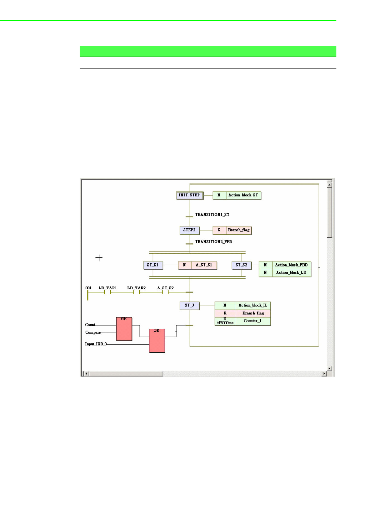
Table 1.1: Programming Languages Table
Textual Languages Graphical Languages
Instruction List (IL)
Structured Text (ST)
Function Block Diagram (FBD)
Ladder Diagram (LD)
Sequential Function Chart (SFC)
Cross-Language Programming
For some project integrate and scalable issues, cross-language can help you to
choose the different language for your project. For example, you can use ladder (LD)
on the simple I/O module control or simple logical expression and use Function Block
(FB) on process control for more advanced expression and use Sequential Function
Chart (SFC) for system configuration in hybrid control system such as Water Treatment.
Figure 1.1 Cross-Language Programming
Deterministic I/O
ADAM-5560 Series Controller can guarantee deterministic I/O at 1ms. The feature
guarantees control and response speed at I/O level so HMI software or operations of
other application programs cannot affect the I/O control performance.
ADAM-5560 Series User Manual 4
Page 13

Real time multi-task engine
ADAM-5560 Series Controller provides the multi-task and multi-program environment. ADAM-5560 Series Controller’s communication, data process and I/O access
tasks are working independent, so the system performance and efficiency are better
than traditional PLC.
Custom Function Block for complex control
ADAM-5560KW Controller allows custom function block for advanced control algorithm such as fuzzy logic control or neural network control function. Users can define
their own function block for common use function or special domain know-how. The
control kernel also provides powerful floating point calculation and rich memory for
complex control.
Pre-defined function library
Advantech Multiprog provides many pre-defined function library such as maximum of
strings as string function block, Convert REAL to INT as type convert function block.
It helps you to build up your program more conveniently. It is more convenient than
the traditional control programming tools. With this pre-defined function, you can
make your project easier in timer control, variable type conversion or strings conversion, etc.
Chapter 1 Overview
Powerful debug / diagnostic / simulation / force tools
Advantech Multiprog provides lots of powerful tools for debug, diagnostic, simulation
and force function. It shows friendly interfaces when you use these tools. With debug
/ diagnostic tools, you can make it easier on trouble-shooting. Advantech Multiprog
simulator supports program verification offline directly on your PC. This is great in
case you are developing logic and you do not have access to a controller. To activate
an I/O simply click on the LED you want to energize and your logic executes as if it
was a real I/O. The program operation is the same as if you actually were connected
to the controller, so all the debug tools are fully functional: power and logic flow, I/O
force and overwriting. With force tools, you can check more exception situations and
check if the project handling right or wrong. It prevents the damage for you.
Online editing & partial download
Online editing is a MUST even though many packages do not support it. It is unacceptable to shut down the machine or process to perform maintenance, not to mention how difficult it is to debug when you have to switch back and forth from program
to run mode. Multiprog supports online editing so you can make changes and then
download the changes to the controller WITHOUT stopping the machine or process.
It helps you to maintain your system easier and save the cost for your system process.
Rich support to ADAM-5560 I/O Modules
Most of the ADAM-5560 I/O modules are supported by ADAM-5560 Series Controller
including analog I/O modules, digital I/O modules and motion control module. All the
operations of supported modules are the same with the operations of ADAM-5510
series.
The ADAM-5560 Series Controller uses a convenient backplane system for
supporting versatile I/O modules. Advantech's complete line of ADAM-5560 I/O modules integrates with the ADAM-5560 Series Controller to support your applications.
Following table is the latest I/O module support list we provided for user’s choice.
5 ADAM-5560 Series User Manual
Page 14

Table 1.2: I/O Module Support List
Function Module Description Reference
ADAM-5013 3 -c h RTD Input Isolated
ADAM-5017 8 -c h AI Isolated
ADAM-5017P 8-ch AI w/Independent Input Range Isolated
Analog Input
Analog Output ADAM-5024 4-ch AO Isolated
Digital Input
Digital Output
Digital I/O
Relay Output
Counter/
Frequency
Communication
Storage ADAM-5030 2-slot SD Storage Module Non-isolated
Motion
ADAM-5017H 8-ch High Speed AI (1 KHz) Isolated
ADAM-5017UH 8-ch Ultra High Speed AI (200KHz) Isolated
ADAM-5018 7 -c h TC Input Isolated
ADAM-5018P 7-ch TC Input w/Independent Input Range Isolated
ADAM-5051 16-ch DI Non-isolated
ADAM-5051D 16-ch DI w/LED Non-isolated
ADAM-5051S 16-ch Isolated DI w/LED Isolated
ADAM-5052 8-ch Isolated DI w/LED Isolated
ADAM-5053S 32-ch Isolated DI Isolated
ADAM-5056 16-ch DO Non-isolated
ADAM-5056D 16-ch DO w/LED Non-isolated
ADAM-5056S 16-ch Isolated DO w/LED Isolated
ADAM-5056SO 16-ch Source Type Isolated DO w/LED Isolated
ADAM-5057S 32-ch Isolated DO Isolated
ADAM-5050 16-ch DI/O Non-isolated
ADAM-5055S 16-ch Isolated DI/O w/LED Isolated
ADAM-5060 6-ch Relay Output Isolated
ADAM-5069 8-ch Power Relay Output w/LED Isolated
ADAM-5081 4 -c h/ 8- ch High Speed Counter/Frequen cy Isolated
ADAM-5091 4-port RS-232 Module Non-isolated
ADAM-5095 2-port CAN Module Isolated
ADMA-5202 2-port AMONet Master Module Isolated
ADAM-5240
4-axis Stepping/Servo Motor Control
Module
Isolated
Note! For details, refer to ADAM-5000 I/O Module User’s Manual.
Dual Ethernet Ports
ADAM-5560 Series Controller provides two Ethernet ports for different application
requirements such as redundant Ethernet connection for reliability concern or separated network connections for security concern. Both of the functions are possible to
be implemented by customer’s application program.
ADAM-5560 Series User Manual 6
Page 15
Remote maintenance via FTP Server and DiagAnywhere Software
For remote maintenance function, the built-in FTP server provides service for uploading application program or downloading data logging files. DiagAnywhere Software is
also supported for remote control, download and upload functions.
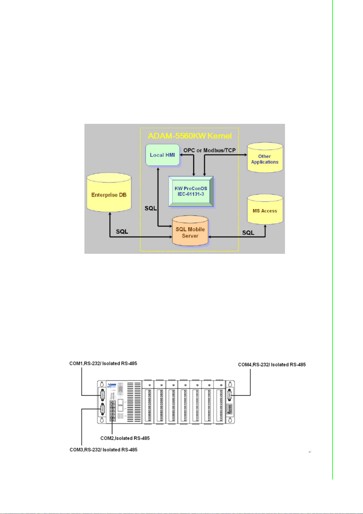
Built-in SQL Mobile Server
ADAM-5560KW Controller embeds SQL server so it is very easy to exchange data
between enterprise database/local HMI software and SQL server by SQL query functions. Following is the Architecture of ADAM-5560KW Controller Kernel.
Chapter 1 Overview
RS-232/485 communication ability
The ADAM-5560 Series Controller has four serial communication ports, giving it
excellent communication abilities. This facilitates its ability to control networked
devices. ADAM-5560 Series Controller COM1/COM3/COM4 are RS-232/485
selectable port and COM2 is a dedicated RS-485 por. These four ports allow the
ADAM-5560 Series Controller to satisfy diverse communication and integration
demands. With this communication ports, you should not buy more I/O communication device and save more costs. You can also extend your system by using these
communication ports. Please refer to following figure and check the location of COM
ports.
Figure 1.2 ADAM-5560 Communication Ports
7 ADAM-5560 Series User Manual
Page 16

Remote I/O Expansibility
ADAM-5560 Series Controller supports not only Modbus/RTU Master function via
serial ports, but also the Modbus/TCP Client to retrieve data from remote I/O, and
Modbus/TCP Server to exchange data with other Modbus devices via Ethernet port.
This Modbus features are very useful when the control system needs expand the
remote I/O modules or connect to other controllers.
1.3 Specifications
1.3.1 System
CPU: Intel ATOM Z510P Processor
Operating system: Windows CE 5.0
Memory: 1 GB DDR2 SDRAM with 1MB Battery Backup
One CompactFlash® Card (Internal)
Real-time clock: Yes
Watchdog timer: Yes
– Operating System Watchdog
– KW application watchdog
– Modbus server communication watchdog
USB Port: USB 2.0 ports * 2
VGA Port: 1024 X 768 Resolution
Ethernet Port: 10M/100M bps * 2
RJ-45 connectors
COM1: RS-232/485 selectable, DB-9 connector
COM2: RS-485, Terminal Block
COM3: RS-232/485 selectable, DB-9 connector
COM4: RS-232/485 selectable, DB-9 connector
I/O capacity: 7 slots
Maximum number of nodes: 256 nodes
System power consumption: 17 W (without I/O modules)
1.3.2 USB Ports
USB 2.0
1.3.3 VGA Port
1024 X 768 Resolution
1.3.4 Ethernet Ports
10M/100M bps x 2
RJ-45 connectors
Transmission Speed 10M/100M bps (10/100 Base-T)
1.3.5 RS-232/485 interface (COM1)
RS-232/485 Mode selectable by jumper
RS-232 Mode: Asynchronous full duplex, point to point
Signals: TxD, RxD, RTS, CTS, DTR, DSR, DCD, RI, GND
RS-485 Mode: Half duplex, multi-drop
Signal: DATA+, DATA-
ADAM-5560 Series User Manual 8
Page 17

Connector: DB-9 pin
Transmission speed: Up to 115.2 Kbps
Max transmission distance:
– RS-232: 50 feet (15.2 m)
– RS-485: 4,000 feet (1220 m)
1.3.6 RS-485 interface (COM2)
Signals: DATA+, DATA-
Mode : Half duplex, multi-drop
Connector: Screw terminal
Transmission speed: Up to 115.2K bps
Max transmission distance: 4000 feet (1220 m)
1.3.7 ES-232/485 interface (COM3) (Suitable for touchscreen)
RS-232/485 Mode selectable by jumper
RS-485 Signal: DATA+, DATA-
RS-232 Mode: Asynchronous full duplex, point to point
Signals: TxD, RxD, RTS, CTS, DTR, DSR, DCD, RI, GND
RS-485 Mode: Half duplex, multi-drop
RS-485 Signal: DATA+, DATA-
Connector: DB-9
Transmission speed: Up to 115.2K bps
Max transmission distance:
– RS-232: 50 feet (15.2 m)
– RS-485: 4000 feet (1220 m)
Chapter 1 Overview
1.3.8 RS-232/485 interface (COM4)
RS-232/485 Mode selectable by jumper
RS-485 Signal: DATA+, DATA-
RS-232 Mode: Asynchronous full duplex, point to point
Signals: TxD, RxD, RTS, CTS, DTR, DSR, DCD, RI, GND
RS-485 Mode: Half duplex, multi-drop
RS-485 Signal: DATA+, DATA-
Connector: DB-9
Transmission speed: Up to 115.2K bps
Max transmission distance:
– RS-232: 50 feet (15.2 m)
– RS-485: 4000 feet (1220 m)
1.3.9 Isolation
COM2: 2500 Vrms
COM1/COM3/COM4: 1000 Vrms (RS-485 only)
1.3.10 Power
Unregulated +10 to +30 VDC
Protected against power reversal
Power consumption: 17 W (not including I/O modules)
9 ADAM-5560 Series User Manual
Page 18
1.3.11 Mechanical
Case: ABS+PC with captive mounting hardware
Plug-in screw terminal block:
Accepts 0.5 mm2 to 2.5 mm2, 1 - #12 or 2 - #14 to #22 AWG
1.3.12 Environment
Operating temperature: 0 ~ 55° C (32 ~ 122° F)
Storage temperature: -25° to 85° C (-13° to 185° F)
Humidity: 5 to 95 %, non-condensing
Atmosphere: No corrosive gases
Note! Equipment will operate below 30% humidity. However, static electricity
problems occur much more frequently at lower humidity levels. Make
sure you take adequate precautions when you touch the equipment.
Consider using ground straps, anti-static floor coverings, etc. if you use
the equipment in low humidity environments.
1.3.13 Software Specifications
Real Time O.S: KW ProConOS (Up to 16 cycle tasks)
Programmable Code/Data Size: up to 710 KB
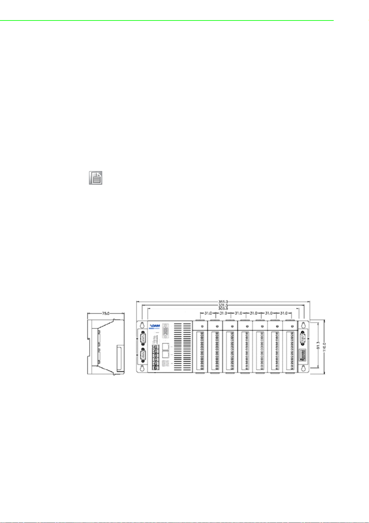
1.4 Dimensions
The following diagrams show the dimensions of the system unit and an I/O unit. All
dimensions are in millimeters.
Figure 1.3 ADAM-5560 Dimensions
1.5 LED Status
There are two LEDs on the front panel of ADAM-5560 Series Controller. The LEDs
indicate operating status, as explained below:
PWR: Power indicator. This LED is on whenever the ADAM-5560 Series Controller is
powered on.
RUN: Blinking while project is running, off while project is stopped.
ADAM-5560 Series User Manual 10
Page 19

There are two LEDs besides each Ethernet port. The LEDs indicate operating status,
as explained below:
TX (Green): This LED blinks whenever the ADAM-5560 Series Controller
transmitting data to Ethernet.
Link (Orange): This LED is on whenever the ADAM-5560 Series Controller
connecting to Ethernet.
1.6 Limitations
1.6.1 Remote I/O Quantity
ADAM-5560 Series Controller can connect to ADAM-4000 Modbus I/O modules
through COM1/COM2/COM3/COM4 RS-485 port by Modbus protocol. (COM2 is also
workable if a RS-232 to RS-485 converter is used.) The typical quantity of remote I/O
connection is 128.
1.6.2 Modbus/RTU Slave Function
ADAM-5560 Series Controller support Modbus/RTU slave function.
1.6.3 TCP/IP Connections
Chapter 1 Overview
Multiprog via Ethernet connection: maximum 4 connections
Modbus/TCP Server connection: maximum 64 connections
Modbus/TCP Client connection: maximum 128 connections
1.6.4 Firmware Upgrade Notice
When you would like to upgrade the firmware of ADAM-5560 Series Controller,
please do contact with Advantech Technical Support Team for support. Wrong procedures will possibly cause potential problem to your system.
1.6.5 Boot-up Time
The boot-up time of ADAM-5560 Series Controller is around 40 seconds.
11 ADAM-5560 Series User Manual
Page 20

ADAM-5560 Series User Manual 12
Page 21

Chapter 2
2 Installation
Page 22

2.1 Overview
This chapter describes how to install an ADAM-5560 Series Controller. A quick
hookup scheme is provided that let you easily configure your system before implementing it into your application.
2.2 System Requirements
Before you start installing the ADAM-5560 Series Controller, make sure the system
requirements are met as below:
2.2.1 Host Computer Requirements
1. IBM PC compatible computer with Pentium II 350MHz processor.
2. Microsoft Windows 95/98/NT4.0 SP5/Windows 2000 SP2 or Windows XP.
3. At least 64 MB RAM.
4. 200 MB of hard disk space available
5. VGA 256 colors monitor, 800x600 resolutions
6. CD-ROM.
7. Mouse or other pointing devices.
8. One Ethernet port
2.2.2 ADAM-5560 Series Requirements
1. 1 x ADAM-5560 Series main unit, i.e., ADAM-5560CE or ADAM-5560KW
2. ADAM-5560 Series User’s Manual
3. One Advantech Multiprog CD.
4. Power supply for ADAM-5560 Series (+10 to +30 VDC unregulated)
5. One Ethernet Hub or Switch like ADAM-6520 or ADAM-6510
2.2.3 I/O Module Requirements
At least one I/O module is needed to use the system. A variety of I/O modules are
available to meet different application requirements. Table 1.2 gives a current listing
of these modules for your reference. In following example, we will use ADAM-5051D
in Slot 0 and ADAM-5056D in Slot 1 on ADAM-5560KW.
ADAM-5560 Series User Manual 14
Page 23

2.3 Hardware Installation
2.3.1 Selecting I/O Module
To organize an ADAM-5560 Series control system, you need to select I/O modules to
interface the main unit with field devices or processes that you have previously determined. There are several things should be considered when you select the I/O modules.
What type of I/O signal is applied in your system?
How many I/O is required to your system?
How will you concentrate the I/O points of an entire process?
What is the required voltage range for each I/O module?
What isolation environment is required for each I/O module?
What are the noise and distance limitations for each I/O module?
Refer to discrete & analog I/O module selection guidelines as below.
Table 2.1: Discrete and Analog I/O Selection Guidelines
Choose this type of I/O
module:
Discrete input module
and block I/O module
Discrete output module
and block I/O module
Analog input module
Analog output module
For these types of field devices or
operations (examples):
Selector switches, push buttons,
photoelectric eyes, limit switches,
circuit breakers, proximity switches,
level switches, motor starter contacts, relay contacts, thumbwheel
switches
Alarms, control relays, fans, lights,
horns, valves, motor starters, solenoids
Thermocouple signals, RTD signals,
temperature transducers, pr ess ur e
transducers, load cell transducers,
humidity transducers, flow transducers, potentiometers.
Analog valves, actuators, chart
recorders, electric motor drives,
analog meters
Chapter 2 Installation
Explanation:
Input modules sense ON/OFF
or OPENED/CLOSED signals. Discrete signals can be
either AC or DC.
Output module signals interface with ON/OFF or
OPENED/CLOSED devices.
Discrete signals can be either
AC or DC.
Convert continuous analog
signals into input values
Interpret output value to analog signals (generally through
transducers) for field devices.
Advantech provides 28 types of ADAM-5560 I/O modules for various applications so
far. The Table 1.2 will help you to select the ADAM-5560 I/O modules quickly and
easily.
15 ADAM-5560 Series User Manual
Page 24
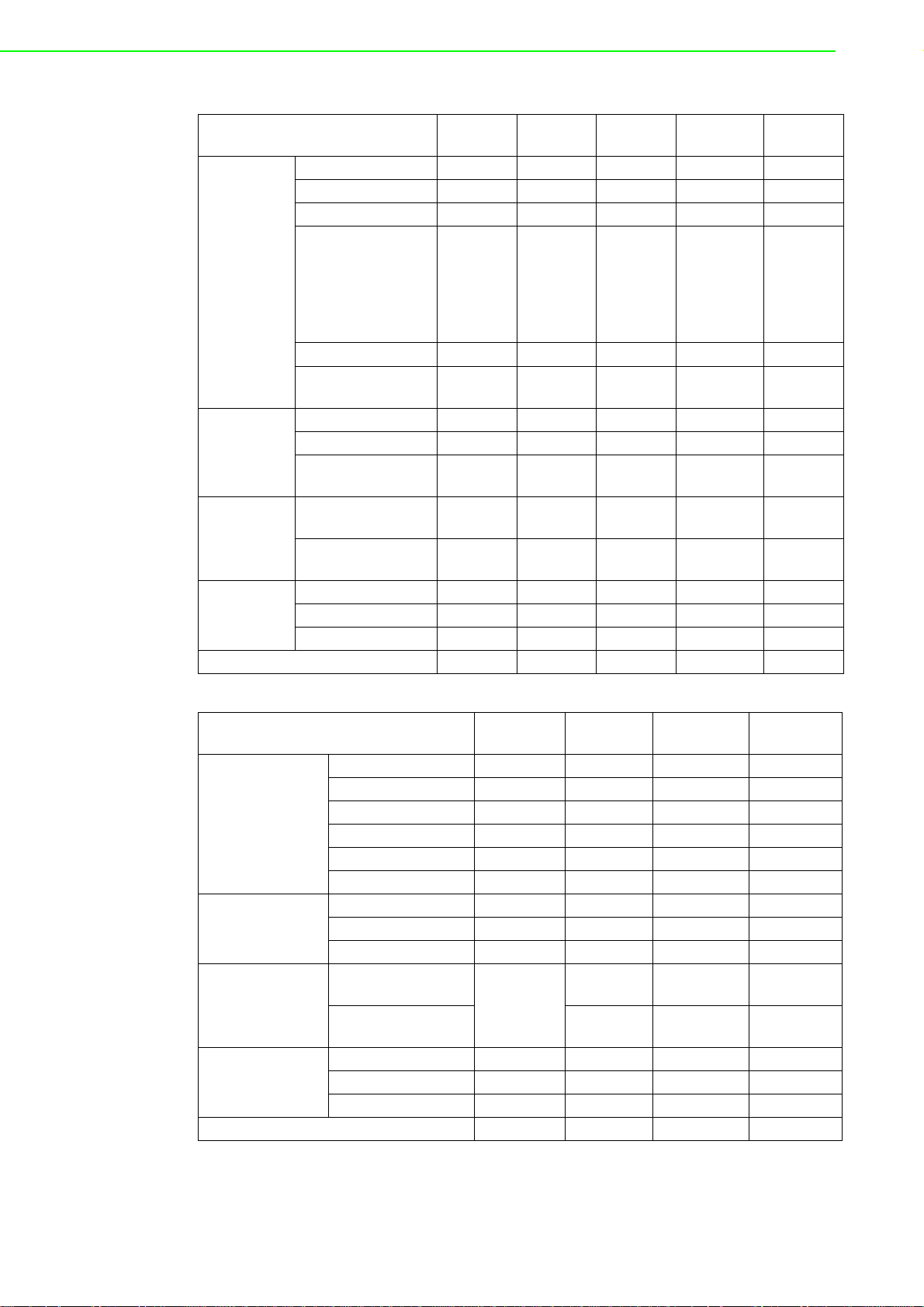
Module
Resolution 16 bit 16 bit 12 bit 16 bit Input Channel 3 8 8 7 Sampling Rate 10 10 8K (Total) 10 -
Analog Input
Analog
Output
Digital Input
and Digital
Output
Counter
(32-bit)
Isolation 3000 VDC 3000 VDC 3000 VDC 3000 VDC 3000 VDC
Voltage Input -
Current Input - ±20 mA 4~20mA ±20 mA Direct Sensor Input
Resolution - - - - 12 bit
Voltage Output - - - - 0~10 V
Current Output - - - Digital Input
Channels
Digital Output
Channels
Channels - - - - Input Frequency - - - - Mode ---- -
ADAM5013
Pt or Ni
RTD
---- -
---- -
ADAM5017
±150 mV
±500 mV
±1 V
±5 V
±10 V
--
ADAM5017UH
±10 V
0~10V
0~20mV
ADAM5018
±15 mV
±50 mV
±100 mV
±500 mV
±1 V
±2.5 V
J, K, T, E,
R, S, B
ADAM5024
-
-
0~20 mA
4~20 mA
Module
Resolution - - - Input Channel - - - -
Analog Input
Analog
Output
Digital Input and
Digital Output
Count-er (32-bit)
Isolation - - - 2500 VDC
Sampling Rate - - - Voltage Input - - - Current Input - - - Direct Sensor Input - - - Resolution - - - Voltage Output - - - Current Output - - - Digital Input
Channels
Digital Output
Channels
Channels - - - Input Frequency - - - Mode - - - -
ADAM5050
16 DIO
(bit-wise
selectable)
ADAM5051
16 16 W/LED 16 W/LED
-- -
ADAM5051D
ADAM5051S
ADAM-5560 Series User Manual 16
Page 25

Chapter 2 Installation
Module
Analog Input
Analog Output
Digital Input and
Digital Output
Count-er (32-bit)
Isolation
ADAM5052
Resolution - - - - Input
Channel
Sampling
Rate
Voltage Input - - - - Current
Input
Direct
Sensor
Input
Resolution - - - - Voltage Output - - - - Current
Output
Digital Input
Channels
Digital Output
Channels
Channels - - - - Input
Frequency
Mode -- -- -
-- -- -
-- -- -
-- -- -
-- -- -
-- -- -
8 8 W/LED - - -
- 8 W/LED 16 16 W/LED 16 W/LED
-- -- -
5000
V
RMS
ADAM5055S
2500 V
ADAM5056
--
DC
ADAM5056D
ADAM5056S /
5056SO
2500V
DC
Module ADAM-5060 ADAM-5069
Resolution - Input Channel - Sampling Rate - -
Analog Input
Analog Output
Digital Input and
Digital Output
Counter (32-bit)
RS-232 Channels - Isolation - -
Voltage Input - Current Input - Direct Sensor
Input
Resolution - Voltage Output - Current Output - Digital Input Channels - -
Digital Output Channels
Channels - -
Input Frequency - Mode - -
--
6 relay
(2 form A/ 4 form C)
8 power relay
(8 form A)
17 ADAM-5560 Series User Manual
Page 26

Module ADAM-5030
SD Card Slot 2
USB 2.0 Slot 2
2.3.2 Selecting Power Supply Module
ADAM-5560 Series Controller works under unregulated power source between +10
and +30 VDC. When you arrange different I/O modules on ADAM-5560 Series Controller’s backplane, it may require comparable power supply. Use the following steps
as guidelines for selecting a power supply for your ADAM-5000 Series control system.
Refer to Table 2.2 to check the power consumption of ADAM-5000 Series Controller
and each I/O module.
Table 2.2: Power Consumptio n of ADAM-5000 series (Main Units)
Main Units Description
ADAM-5000/485
ADAM-5000
ADAM-5000/TCP
ADAM-5510
ADAM-5510M
ADAM-5511 PC-Based Programmable Controller with Modbus 1.0 W
ADAM-5510E 8-slot PC-Based Programmable Controller 1.2 W
ADAM-5510/TCP
ADAM-5510E/TCP
ADAM-5510KW PC-based SoftLogic Controller 1.2 W
ADAM-5510EKW 8-slot PC-based SoftLogic Controller 1.2 W
ADAM-5510EKW/TP 8-slot Ethernet-enabled SoftLogic Controller 2.0 W
ADAM-5560 8-slot Programmable Automation Controller 17 W
Distributed Data Acquisition and Control System
based on RS-485
Distributed Data Acquisition and Control System
based on RS-485
Distributed Data Acquisition and Control System
based on Ethernet
PC-Based Programmable Controller (With Battery
Backup)
Enhanced PC-Based Programmable Controller (With
Battery Backup)
Ethernet-enabled PC-Based Programmable
Controller
8-slot Ethernet-enabled PC-Based Programmable
Controller
Power
Consumption
1.0 W
4.0 W
5.0 W
1.0 W
1.2 W
2.0 W
2.0 W
ADAM-5560 Series User Manual 18
Page 27

Table 2.3: Power Consumption of ADAM-5000 series (IO Modules)
ADAM-5013 3-Channel RTD Input Module 1.1 W
ADAM-5017 8-Ch Analog Input Module (mV, mA or High Voltage) 1.25 W
ADAM-5017UH
ADAM-5018
ADAM-5024 4-Channel Analog Output Module (V, mA) 2.9 W
ADAM-5050 16-Channel Universal DIO 1.2 W
ADAM-5051 16-Channel Digital Input Module 0.53 W
ADAM-5051D 16-Channel Digital Input w/LED Module 0.84 W
ADAM-5056S 16-Channel Isolated Digital Input w/LED Module 0.8 W
ADAM-5056SO 16-Channel Digital Input w/LED Module 0.84 W
ADAM-5052 8-Channel Isolated DI 0.27 W
ADAM-5055S 16-Channel Isolated DIO w/LED Module 0.68 W
ADAM-5056 16-Channel Digital Output Module 0.53 W
ADAM-5056D 16-Channel Digital Output w/LED Module 0.84 W
ADAM-5056S 16-Channel Isolated Digital Output w/LED Module 0.6 W
ADAM-5060
ADAM-5068 8-Channel Relay Output Module ( 8 Form A) 1.8 W
ADAM-5069 8-Channel Power Relay Output Module ( 8 Form A) 2.2 W
ADAM-5202 2-Ring AMONet Motion Control Module 2.5 W
8-CH Ultra High speed Analog Input Module (mV, mA
or High Voltage)
7-Channel Thermocouple Input Module (mV, V, mA,
Thermocopule)
6-Ch Relay Output Module ( 2 of Form A, 4 of Form
C)
2.2 W
0.63 W
1.8 W
Chapter 2 Installation
Calculate the Summary of the whole system’s power consumption.
For example, there are following items in your system.
ADAM-5550KW * 3 & ADAM-5024 * 2 & ADAM-5017 * 4 &
ADAM-5068 * 2 & ADAM-5056D * 2
The power consumption is:
17 W * 3 + 2.9 W * 2 + 1.25 * 4 + 1.8 W * 2 + 0.84 W * 2 = 67.08 W
19 ADAM-5560 Series User Manual
Page 28

Select a suitable power supply from Table 2.4 or other comparable power resource
for system operation.
Table 2.4: Power Supply Specification Table
Specification PWR-242 PWR-243 PWR-244
Input
Input Voltage 90 ~ 264 V
Input Frequency 47 ~ 63 Hz 47 ~ 63 Hz 47 ~ 63 Hz
Input Current 1.2 A max. 1.4 A max
Short Protection Yes Yes Yes
Output
AC
85 ~ 132 V AC
170 ~ 264 VAC
100 ~ 240 VAC
25 A/110 V
50 A/220 VAC
(Inrush current)
AC
Output Voltage +24 V
Output Current 2.1 A 3 A 4.2 A
Overload Protection Yes Yes Yes
General
Dimension
Operating Temperature 0 ~ 50C (32 ~ 122F) 0 ~ 50C (32 ~ 122F) 0 ~ 50C (32 ~ 122F)
DIN-rail Mountable Yes No No
DC +24 VDC +24 VDC
181mm x 113 mm x
60 mm
(L x W x H)
181mm x 113 mm x
60 mm
(L x W x H)
2.3.3 Install Main Unit and Modules
While inserting modules into the system, align the PC board of the module with the
grooves on the top and bottom of the system. Push the module straight into the system until it is firmly seated in the backplane connector. Once the module is inserted
into the system, push in the retaining clips (located at the top and bottom of the module) to firmly secure the module to the system.
2.3.4 I/O Slots and I/O Channel Numbering
The ADAM-5560 Series provides 7 slots for I/O modules. The I/O slot s are numbered
0 through 6, and the channel numbering of any I/O module in any slot starts from 0.
For example, the ADAM-5017 is an 8-channel analog input module. Its input channel
numbering is 0 through 7.
181mm x 113 mm x
60 mm
(L x W x H)
ADAM-5560 Series User Manual 20
Page 29
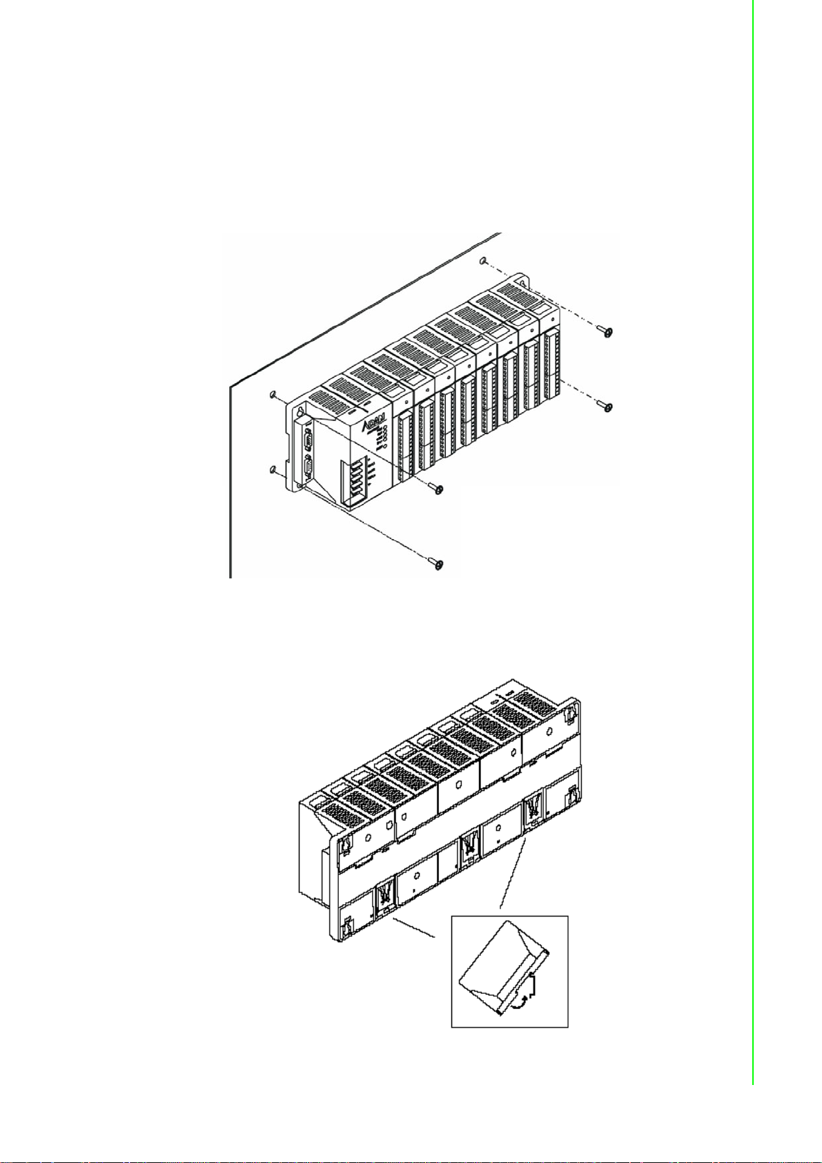
2.3.5 Mounting
The ADAM-5560 Series Controller can be installed on a panel or on a DIN rail.
2.3.5.1 Panel Mount
Mount the system on the panel horizontally to provide proper ventilation. You cannot
mount the system vertically, upside down or on a flat horizontal surface. A standard
#7 tatting screw (4 mm diameter) should be used.
Chapter 2 Installation
2.3.5.2 DIN-rail Mounting
Figure 2.1 Panel Mount for ADAM-5560 Series
Figure 2.2 DIN-rail Mounting
21 ADAM-5560 Series User Manual
Page 30

The system can also be secured to the cabinet by using mounting rails. If you mount
the system on a rail, you should also consider using end brackets at each end of the
rail. The ended brackets help keep the system from sliding horizo ntally along the rail.
This minimizes the possibility of accidentally pulling the wiring loose. If you examine
the bottom of the system, you will notice two small retaining clips. To secure the system to a DIN rail, place the system on to the rail and gently push up on the retaining
clips. The clips lock the system on the rail. To remove the system, pull down on the
retaining clips, lift up on the base slightly, and pull it away from the rail.
2.3.6 Jumper and DIP Switch Setting s
This section tells you how to set the jumpers and DIP switches to configure your
ADAM-5560 Series Controller. It gives the system default configuration and your
options for each jumper and dip switch. The backplane has one 8-pin DIP switch and
twelve jumpers on it.
2.3.6.1 RS-232/485 Selectable Jumper Setting
Following figure shows the COM1 to COM4 location.
Figure 2.3 COM Port Location
The Communication mode of COM1, COM3 and COM4 are set by jumpers on the
backplane. Please refer to Figure 2.4 to get the jumper locations.
Figure 2.4 COM1/COM4 RS-232/485 Settings
ADAM-5560 Series User Manual 22
Page 31

COM1 Jumper Setting
The Communication port of COM1 is set by CN4, CN5, CN6 (Mode) and CN7 (Terminal Resistor).
Figure 2.5 COM1 RS-232/485 and Terminal Resistor Settings
COM3 Jumper Setting
The Communication port of COM3 is set by CN9, CN10, CN11 (Mode) and CN12
(Terminal Resistor).
Chapter 2 Installation
Figure 2.6 COM3 RS-232/485 and Terminal Resistor Settings
COM4 Jumper Setting
The Communication port of COM4 is set by CN14, CN15, CN16 (Mode) and CN1
7(Terminal Resistor).
Figure 2.7 COM4 RS-232/485 and Terminal Resistor Settings
23 ADAM-5560 Series User Manual
Page 32

2.3.6.2 DIP Switch Setting
Device ID Setting:
You can set up your device ID by changing DIP Switch 1-8. The available ID for
ADAM-5560 Series Controller is from 0 to 255. Please refer to the Table 2.6 Device
ID DIP Switch Table to set up your Device ID.
Table 2.5: Device ID DIP Switch Table
Figure 2.8 ADAM-5560 Series DIP Switch
DIP 8
7
)
(2
Off Off Off Off Off Off Off Off 0
Off Off Off Off Off Off Off On 1
Off Off Off Off Off Off On Off 2
Off Off Off Off Off Off On On 3
Off Off Off Off Off On Off Off 4
Off Off Off Off Off On Off On 5
Off Off Off Off Off On On Off 6
Off Off Off Off Off On On On 7
Off Off Off Off On Off Off Off 8
... ... ... ... ... ... ... ... ...
On On On On On On Off Off 252
On On On On On On Off On 253
On On On On On On On Off 254
On On On On On On On On 255
DIP 7
(26)
DIP 6
(25)
DIP 5
(24)
DIP 4
(23)
DIP 3
(22)
DIP 2
(21)
DIP 1
(20)
Device ID
ADAM-5560 Series User Manual 24
Page 33

2.3.7 COM Port Pin Assignments
Figure 2.9 RS-232 Port Pin Assignment
Chapter 2 Installation
Figure 2.10 RS-485 Port Pin Assignment
25 ADAM-5560 Series User Manual
Page 34

2.4 System Wiring and Connections
This section provides basic information on wiring the power supply, I/O modules and
communication port connection.
2.4.1 Power Supply Wiring
Although the ADAM-5560 Series Controller is designed for a standard industrial
unregulated 24 V
range of +10 to +30 V
peak, and the immediate ripple voltage should be maintained between +10 and +30
V
. Screw terminals +Vs and GND are for power supply wiring.
DC
Note! The wires used should be sized at least 2 mm.
power supply , th ey accept any power unit th at supplies within the
DC
. The power supply ripple must be limited to 200 mV peak-to-
DC
Figure 2.11 ADAM-5560 Series Controller Power Wiring
2.4.2 I/O Module Wiring
The system uses a plug-in screw terminal block for the interface between I/O modules and field devices. The following information must be considered when connecting electrical devices to I/O modules.
1. The terminal block accepts wires from 0.5 mm 2 to 2.5 mm.
2. Always use a continuous length of wire. Do not combine wires to make them
longer.
3. Use the shortest possible wire length.\
4. Use wire trays for routing where possible.
5. Avoid running wires near high energy wiring.
6. Avoid running input wiring in close proximity to output wiring where possible.
7. Avoid creating sharp bends in the wires.
2.4.3 Connection of Communication Ports
The ADAM-5560 Series Controller has four communication ports. These ports allow
you to integrate the remote devices.
ADAM-5560 Series User Manual 26
Page 35

2.4.3.1 Remote I/O Wiring
Modbus/RTU Master Function via COM1/COM2/COM4 RS-485:
Chapter 2 Installation
Figure 2.12 Remote I/O Wiring
You can connect typical 128 ADAM-4000 Modbus Remote I/O modules via COM1/
COM2/COM4. Please set the COM1 and COM4 as RS-485 mode.
2.4.4 Ethernet Network Connection
The ADAM-5560 Series Controller provides Ethernet interfaces for network integration. Usually, you will need to prepare an ADAM-6520 Ethernet switch or hub for connecting to other network devices as following figure.
Figure 2.13 Ethernet Network Connection
27 ADAM-5560 Series User Manual
Page 36

ADAM-5560 Series User Manual 28
Page 37

Chapter 3
3 Quick Start
Page 38

This chapter will help you get familiar with ADAM-5560KW Controller and Multiprog
Programming Software by following step by step examples.
In this chapter, you need to prepare the system configuration as below.
Main Module:
ADAM-5560KW X1, IP Address: 192.168.1.5
Local I/O Modules:
ADAM-5051D in Slot 0
ADAM-5056D in Slot 1
Advantech Multiprog CD:
Advantech Multiprog Software with license key.
Note! In following chapters of step by step examples, you will see the screen
of ADAM-5560KW in Windows CE with [PAC Device] description and
the screen of PC in Windows XP.
Power wiring
System Wiring
ADAM-5560 Series User Manual 30
Page 39

3.1 Set IP Address to ADAM-5560KW
1. [PAC Device] Power up ADAM-5560KW and click “Start”.
Chapter 3 Quick Start
2. [PAC Device] Click “Settings” and “Network and Dial-up Connections”.
31 ADAM-5560 Series User Manual
Page 40

3. [PAC Device] Right click “PCI-RTL81391” icon and then click “Properties”.
4. [PAC Device] Type IP Address like “192.168.1.5” and Subnet Mask
“255.255.255.0”.
ADAM-5560 Series User Manual 32
Page 41

5. [PAC Device] Right click “PCI-RTL81392” icon and then click “Properties”.
Chapter 3 Quick Start
6. [PAC Device] Type IP Address like “192.168.1.6” and Subnet Mask
“255.255.255.0”. Now the IP address configuration has been finished.
33 ADAM-5560 Series User Manual
Page 42

7. If your PC has installed DiagAnywhere Software, you can search the ADAM-
5560KW and check the Ethernet connection. Please click the “Remote device”
and click “Search” button.
8. Click “ADAM-5560” and then click OK button without entering any password.
ADAM-5560 Series User Manual 34
Page 43

9. The screen of ADAM-5560KW will be shown in the window . Now it is p ossible to
remotely control the ADAM-5560KW by PC’s mouse.
Chapter 3 Quick Start
3.2 Configure ADAM-5000 Local I/O
1. [PAC Device] Click “Start” -> “Programs” -> “Advantech” -> “Adam.NET Utility”.
35 ADAM-5560 Series User Manual
Page 44

2. [PAC Device] Click “Local system” to view the local I/O modules.
3. [PAC Device] ADAM-5051 and ADAM-5056 are listed. Select “ADAM-5051”.
ADAM-5560 Series User Manual 36
Page 45

4. [PAC Device] Check the state of DI 0 is “ON”.
Chapter 3 Quick Start
5. [PAC Device] Change the state of DI 0 to “OFF” and check the display.
37 ADAM-5560 Series User Manual
Page 46

6. [PAC Device] Select “ADAM-5056”.
7. [PAC Device] Change the state of DO 0, DO 2, DO 4, DO 6, DO 8, DO 10,DO
12, DO 14 to “ON” and check the display.
ADAM-5560 Series User Manual 38
Page 47

3.3 Multiprog Installation
Following will guide you how to setup Multiprog IEC-61131-3 development environment on your PC.
1. Please use your web browser to visit Advantech web site. (www.advan-
tech.com)
2. Ty pe "ADAM-5560" on the search box which is on the right-up corner of the web
page.
3. Enter the "Utility" category in the download page.
4. Advantech provide customer a 30 days free trial version Multiprog with full func-
tion support. You can download it directly from the web site or from the FTP site.
5. After download all the software package from the web site, please follow the
instructions to install them one by one to setup the development environment.
6. Please contact your sales representative to buy the license, Advantech will send
you a letter with registration code.
3.4 Create a Project and Test the System
In following demonstration, a simple project of performing DI and DO function by ladder diagram is shown. After finish this section, you can ensure the system is workable.
1. Open Advantech Multiprog by clicking Multiprog item.
Chapter 3 Quick Start
39 ADAM-5560 Series User Manual
Page 48

2. Click “OK” to enter the DEMO Mode.
3. Click “Register” to enter the Registration Code.
ADAM-5560 Series User Manual 40
Page 49

4. Enter the Registration Code which comes with Advantech Multiprog Software
License Sheet.
Chapter 3 Quick Start
5. Click “OK” to finish the registration.
41 ADAM-5560 Series User Manual
Page 50

6. Open a new project and start to create the test project.
7. Select “ADAM-5560KW” item and then click “OK”.
ADAM-5560 Series User Manual 42
Page 51
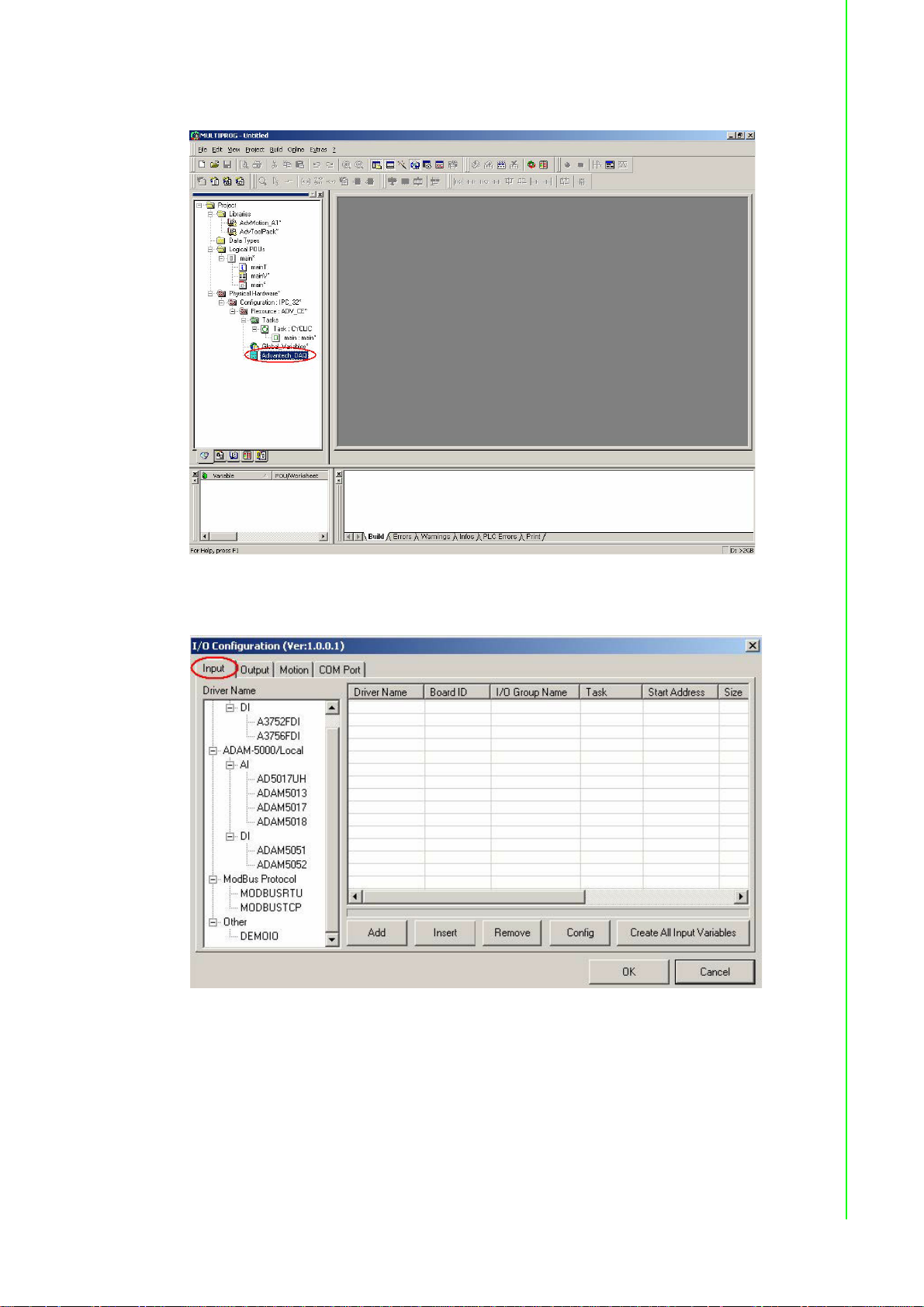
8. Double click “Advantech DAQ” item.
Chapter 3 Quick Start
9. Check the folder is at “Input”.
43 ADAM-5560 Series User Manual
Page 52

10. Select “ADAM5051” and then click “Add”.
11. Select “0” for “Board ID”. Set “0” to “Start Address” and then click “OK”.
ADAM-5560 Series User Manual 44
Page 53

12. Click “Create All Input Variables” and then click “OK”.
13. Click “Output” folder. Select “ADAM5056” and then click “Add”.
Chapter 3 Quick Start
45 ADAM-5560 Series User Manual
Page 54
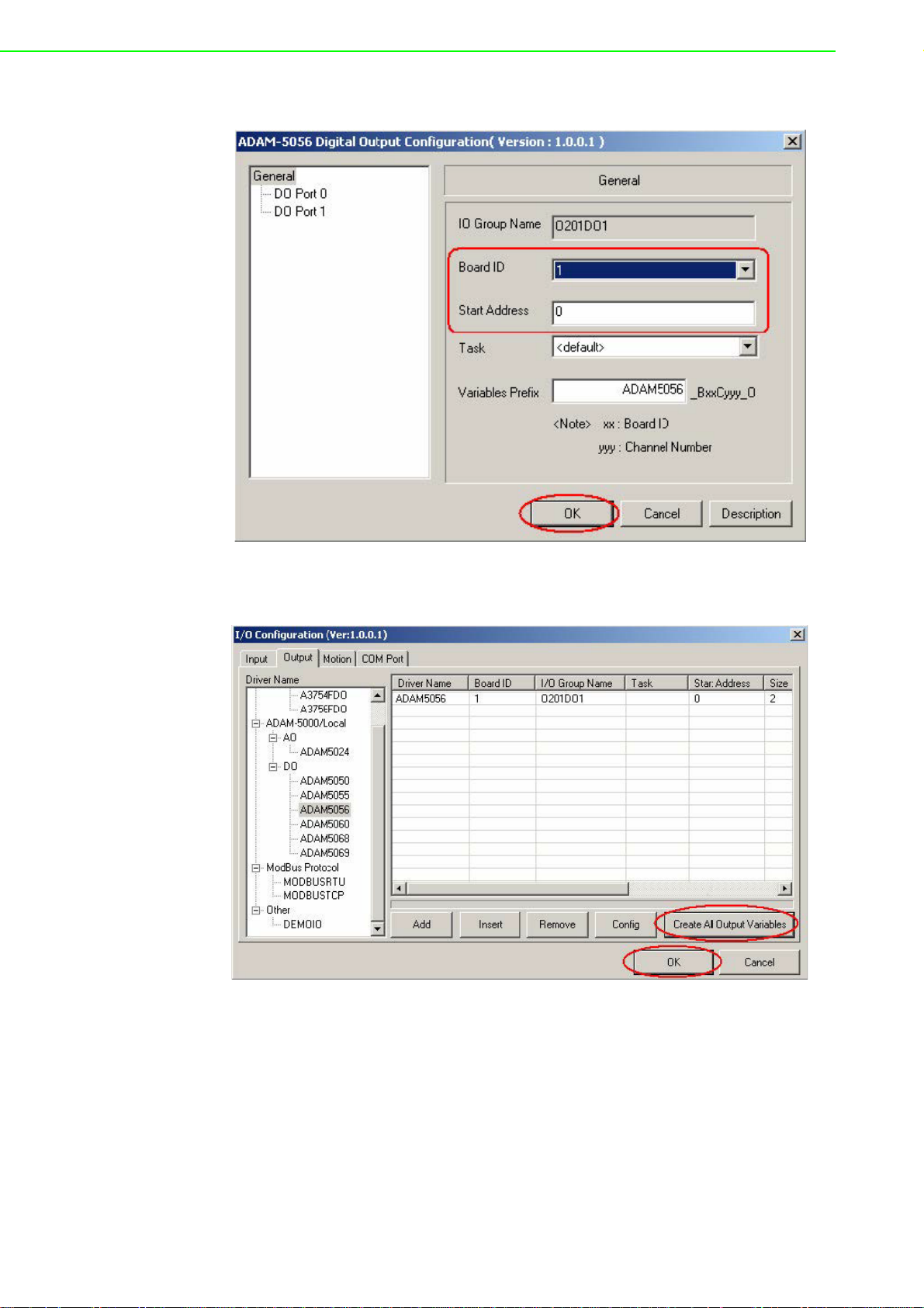
14. Select “1” for “Board ID”. Set “0” to “Start Address” and then click “OK”.
15. Click “Create All Input Variables” and then click “OK”.
ADAM-5560 Series User Manual 46
Page 55

16. Double click “main” and graphical worksheet will be shown.
Chapter 3 Quick Start
17. Click on the graphical editor and ladder objects will be activated.
47 ADAM-5560 Series User Manual
Page 56

18. Add a contact network.
19. Double click “C000”.
ADAM-5560 Series User Manual 48
Page 57

20. Dialog box of “Contact/Coil Property” will be shown.
Chapter 3 Quick Start
21. Click “Global scope”. Select “In_ADAM5051_0_0” and then click “Apply”.
49 ADAM-5560 Series User Manual
Page 58

22. “Common” folder will be shown. Click “Contact” folder.
23. Click “Global”. Select “ADAM5051_B00C000_I” and then click “Apply”.
ADAM-5560 Series User Manual 50
Page 59

24. Click “OK”.
Chapter 3 Quick Start
25. Double click “C001”.
51 ADAM-5560 Series User Manual
Page 60

26. Click “Global”. Select “ADAM5056_B01C000_O” and then click “Apply”.
27. Click “OK”.
ADAM-5560 Series User Manual 52
Page 61

28. Back to graphical editor.
Chapter 3 Quick Start
29. Right click “Resource: ADV_CE” and then click “Settings”.
53 ADAM-5560 Series User Manual
Page 62

30. Type IP Address of ADAM-5560KW as “192.168.1.5”.
31. Click “Make” to build the execution file. Check the project has been compiled
successfully.
ADAM-5560 Series User Manual 54
Page 63

32. Click “Project Control Dialog” and then click “Download”.
Chapter 3 Quick Start
33. Check “Include boot project” and then click “Download”.
55 ADAM-5560 Series User Manual
Page 64

34. Downloading execution file to ADAM-5560KW.
35. Click “Cold” to execute a cold start. During a cold start all data are initialized.
ADAM-5560 Series User Manual 56
Page 65

36. Click “Debug On/Off” to turn on the debug function. The ADAM-5560KW is run-
ning correctly when you see the status bar turns green color. You can see the
DI0 and DO0 are turned blue color. It means the state is FALSE.
Chapter 3 Quick Start
37. When you change the state of ADAM-5051D CH0 as ON, ADAM-5056 CH0
turns ON correctly. The DI0 and DO0 on graphical editor are turned red color
too. It means the state is TRUE.
57 ADAM-5560 Series User Manual
Page 66

38. Finish the test project and do not forget to save it properly.
ADAM-5560 Series User Manual 58
Page 67

3.5 Special Module Support in KW
ADAM-5050 is one of mix digital input/output module and each channel can be independently configured to be an input or an output channel by the setting of its DIP
switch (Please refer the user manual of ADAM-5000 IO Module to get more detail).
For the ADAM-5050 configuration in MultiProg KW, we define it as an output module
only. The IO address will show as %QX by channel.
Chapter 3 Quick Start
In program, you still can read the status of the output as the input signal that you
define it as an input by hardware DIP switch.
59 ADAM-5560 Series User Manual
Page 68

ADAM-5560 Series User Manual 60
Page 69

Chapter 4
4 Modbus Functions
Page 70

4.1 Introduction
The Modbus functions of ADAM-5560KW Controller are powerful features which provide high expansibility and flexibility for user’s applications. The supported modbus
functions include following items.
Modbus/RTU Master Function: Connect to Modbus/RTU remote I/O modules
such as Modbus modules of ADAM-4000 series.
Modbus/TCP Client Function: Connect to Modbus/TCP remote I/O modules
such as ADAM-6000 series.
Modbus/TCP Server Function: Connect to HMI/SCADA software via Ethernet
port.
4.2 Modbus/TCP Client Function
The Modbus/TCP client function can connect to Modbus devices with Modbus/TCP
server function, for example, ADAM-5560/TCP and ADAM-6000 series I/O modules.
Following example can show how to connect to ADAM-6050 by Modbus/TCP client
function.
ADAM-6050 settings:
IP address: 192.168.1.12
ADAM-5560 Series Controller settings:
Slot 0: ADAM-5051D
Slot 1: ADAM-5056D
IP address: 192.168.1.5
System Wiring:
ADAM-5560 Series User Manual 62
Page 71

4.2.1 An example to demonstrate how to connect to ADAM-6050 for
Modbus/TCP client function
1. [PAC Device] Run ADAM.NET utility by clicking “Start” -> “Programs” ->
“Advantech” -> AdamNET Utility.
Chapter 4 Modbus Functions
2. [PAC Device] Select “ADAM5000TCP_6000” item.
63 ADAM-5560 Series User Manual
Page 72
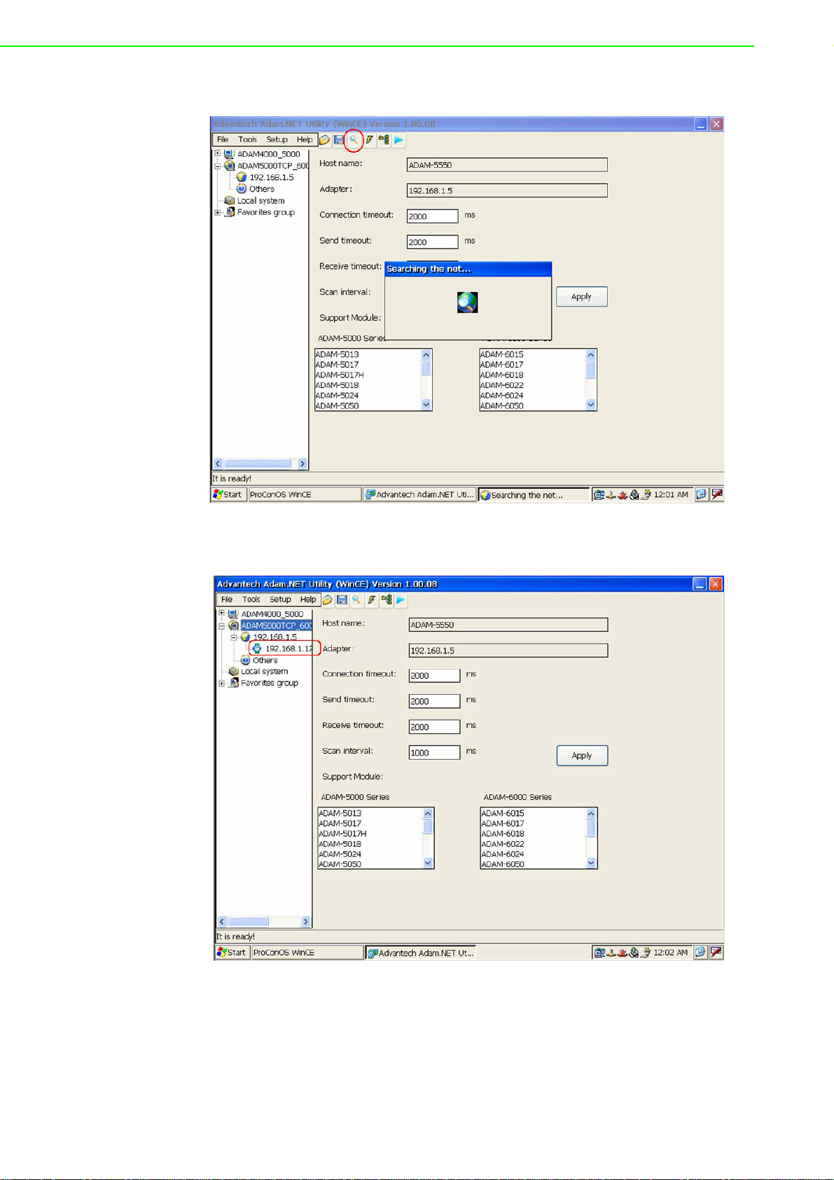
3. [PAC Device] Click “Search” button.
4. [PAC Device] Click “192.168.1.12” item and then “6050” item will show.
ADAM-5560 Series User Manual 64
Page 73

5. [PAC Device] Click “6050” item to see the channel setting.
Chapter 4 Modbus Functions
6. [PAC Device] Enter “00000000” and then click “OK” button.
65 ADAM-5560 Series User Manual
Page 74

7. [PAC Device] Check ADAM-6050 DI bit 0 is OFF.
8. [PAC Device] Turn on ADAM-6050 DI bit 0 and make sure the status is ON in
the utility.
ADAM-5560 Series User Manual 66
Page 75

9. [PAC Device] ADAM-6050 setting is correct. Exit from the ADAM.NET utility.
Chapter 4 Modbus Functions
10. Open “Test.mwt” and follow the example in section 3.4.
67 ADAM-5560 Series User Manual
Page 76

11. Double-click “main” to show the program in graphical editor.
12. Double-click “Advantech_DAQ” to show the “I/O Configuration” dialog box.
ADAM-5560 Series User Manual 68
Page 77

13. Click “MODBUSTCP” item and then click “Add” button.
14. Set Modbus Command: “1X”, Slave ID: 1, Slave IF: “192.168.1.12”, Data Type:
“BOOL”, Start Address: “1”, No. of points: 12.
Chapter 4 Modbus Functions
69 ADAM-5560 Series User Manual
Page 78

15. Click “Create All Input Variables” then click “OK” button.
16. Click “Contact Network” button.
ADAM-5560 Series User Manual 70
Page 79

17. Double-click “C002”.
Chapter 4 Modbus Functions
18. Click “Gloabal scope” folder.
71 ADAM-5560 Series User Manual
Page 80

19. Select “In_MBTCPDRV_0_1” and then click “Apply”.
20. Click “Contact” folder.
ADAM-5560 Series User Manual 72
Page 81

21. Select “MBTR_1X0001_BOOL_00” and then click “Apply”.
Chapter 4 Modbus Functions
22. Check the setting is correct and then click “OK”.
73 ADAM-5560 Series User Manual
Page 82

23. Double-click “C003”.
24. Select “ADAM5056_B01C001_0” and then click “Apply”.
ADAM-5560 Series User Manual 74
Page 83

25. Check the setting is correct and then click “OK”.
Chapter 4 Modbus Functions
26. Click “Make” button to make the execution file.
75 ADAM-5560 Series User Manual
Page 84

27. Check compile result is correct.
28. Click “Project Control Dialog” and then click “Stop” and “Reset”.
ADAM-5560 Series User Manual 76
Page 85

29. Click “Download” button. Check the “Include Bootproject” item and then click
“Download” button to proceed with the download process.
Chapter 4 Modbus Functions
30. Execution file is downloading.
77 ADAM-5560 Series User Manual
Page 86

31. Click “Cold” to run the project.
32. Check the status of ADAM-6050 DI bit 0 and ADAM-5056D DO bit 1 are OFF.
ADAM-5560 Series User Manual 78
Page 87

33. Turn on ADAM-6050 DI bit 0 and check the status of ADAM-5056D DO bit 1 is
turned ON correctly.
Chapter 4 Modbus Functions
34. Save the project properly.
79 ADAM-5560 Series User Manual
Page 88

4.3 Modbus/RTU Master Function
The Modbus/RTU master function is supported by COM1/COM2/COM4 RS-485 Ports
of ADAM-5560 Series Controller. There are typical 128 I/O modules can be connected
to each COM port. So far, there are 12 modules of ADAM -4000 Series support modbus protocol as following list. (Please refer to ADAM-4000 User’s Manual for latest
support list.)
Module Name Description
ADAM-4015 6-channel RTD Input Module
ADAM-4015T 6-channel Thermistor Input Module
ADAM-4017+ 8-channel Analog Input Module
ADAM-4018+ 8-channel Thermocouple Input Module
ADAM-4022T Dual-loop PID Controller
ADAM-4024 4-channel Analog Output Module
Module Name Description
ADAM-4051 16-channel Isolated Digital Input Module
ADAM-4055 16-channel Isolated Digital Input/Output Module
ADAM-4056S 12-channel Sink Type Isolated Digital Output Module
ADAM-4056SO 12-channel Source Type Isolated Digital Output Module
ADAM-4068 8-channel Relay Output Module
ADAM-4069 8-channel Power Relay Output Module
4.3.1 Modbus/RTU Master Function Example
ADAM-4018+ settings:
ID address: 01
Typr K thermocouple applied to CH0 (0~1370ºC)
ADAM-6050 settings: (for following previous example)
IP address: 192.168.1.12
ADAM-5560 Series Controller settings:
Slot 0: ADAM-5051D
Slot 1: ADAM-5056D
IP address: 192.168.1.5
ADAM-5560 Series User Manual 80
Page 89

System Wiring:
COM4 Jumper Settings:
Chapter 4 Modbus Functions
Note! After changing the jumper settings, please reset the ADAM-5560 Series
Controller.
81 ADAM-5560 Series User Manual
Page 90

RS-485 Port Pin Assignment:
1. [PAC Device] Run ADAM.NET utility by clicking “Start” -> “Programs” ->
“Advantech” -> AdamNET Utility.
ADAM-5560 Series User Manual 82
Page 91

2. [PAC Device] Select “ADAM4000_5000” item.
Chapter 4 Modbus Functions
3. [PAC Device] Select “COM4” and then click “Search” button.
83 ADAM-5560 Series User Manual
Page 92

4. [PAC Device] Click “Start” button and “4018P” will be shown.
5. [PAC Device] Click “4018P” to see the module setting.
ADAM-5560 Series User Manual 84
Page 93

6. [PAC Device] Click “Data area” to check the reading of Channel 0 is correct.
This channel will be used by following demonstration.
Chapter 4 Modbus Functions
7. [PAC Device] Select “COM4” and then click “Adam Commander” button.
85 ADAM-5560 Series User Manual
Page 94

8. [PAC Device] Input “#010” and click “Send”. Check the response of the CH0
reading is correct.
9. [PAC Device] Set the ADAM-4018+ to initial mode by changing the switch
position to “Init” side and then resetting the module. The switch is at the left side
of the module. After that, select “COM4” and then click “Search” button again.
ADAM-5560 Series User Manual 86
Page 95

10. [PAC Device] Click “Start” and “4018(*)” will be shown. “*” represents the
module is at initial mode.
Chapter 4 Modbus Functions
11. [PAC Device] Select “4018P(*)” and then change the Protocol setting to
“Modbus”.
87 ADAM-5560 Series User Manual
Page 96

12. [PAC Device] Click “OK” to change the setting.
13. [PAC Device] Select “Data area” and check the CH0 reading. Click “WaveScan”
to see the wavescan window.
ADAM-5560 Series User Manual 88
Page 97

14. [PAC Device] Check CH0 reading and then close the window.
Chapter 4 Modbus Functions
15. [PAC Device] Set the ADAM-4018+ to normal mode by changing the switch
position to “Normal” side and then resetting the module. After that, select
“COM4” and then click “Search” and “Start” buttons.
89 ADAM-5560 Series User Manual
Page 98

16. [PAC Device] Click “4018P(01)” to see the module setting.
17. [PAC Device] Select “Data area” folder and check CH0 reading.
ADAM-5560 Series User Manual 90
Page 99

18. [PAC Device] Select “COM4” and then click “Adam Commander”.
Chapter 4 Modbus Functions
19. [PAC Device] Change to “MODBUS” folder.
91 ADAM-5560 Series User Manual
Page 100

20. [P AC De vice] Check the reading of CH0. The formula is ( 1215*1370) / 65 536 =
25.4 ºC.
21. Open the “Test.mwt” project and then double-click “main”.
ADAM-5560 Series User Manual 92
 Loading...