

Page 1
Total Access SHDSL T1/E1 Line Terminating Unit
Installation and Maintenance Practice
CONTENTS
1. General ................................................................... 1
2. Description ............................................................. 1
3. Installation.............................................................. 2
4. Provisioning ........................................................... 4
5. Operation................................................................ 5
6. Maintenance ........................................................... 9
7. Specifications ......................................................... 9
8. Warranty and Customer Service ............................ 9
FIGURES
Figure 1. SHDSL T1/E1 LTU Front Panel ................ 1
Figure 2. Typical System Application ....................... 2
Figure 3. SHDSL T1/E1 LTU Menu Tree ................. 6
TABLES
Table 1. Compliance Codes ...................................... 2
Table 2. Front Panel LEDs ....................................... 3
Table 3. Account Names and Passwords .................. 4
Table 4. Configuration Options List ......................... 7
Table 5. E1 Port Statistics Definitions...................... 8
Table 6. T1 Port Statistics Definitions...................... 9
Table 7. SHDSL T1/E1 LTU Specifications ............ 9
Section 61182210L1-5A
Issue 1, August 2003
SHDSL
1182210L1
PWR
SHDSL
T1/E1
TEST
ALM
1. GENERAL
This document is an installation and maintenance
practice for the ADTRAN Total Access
®
SHDSL T1/E1
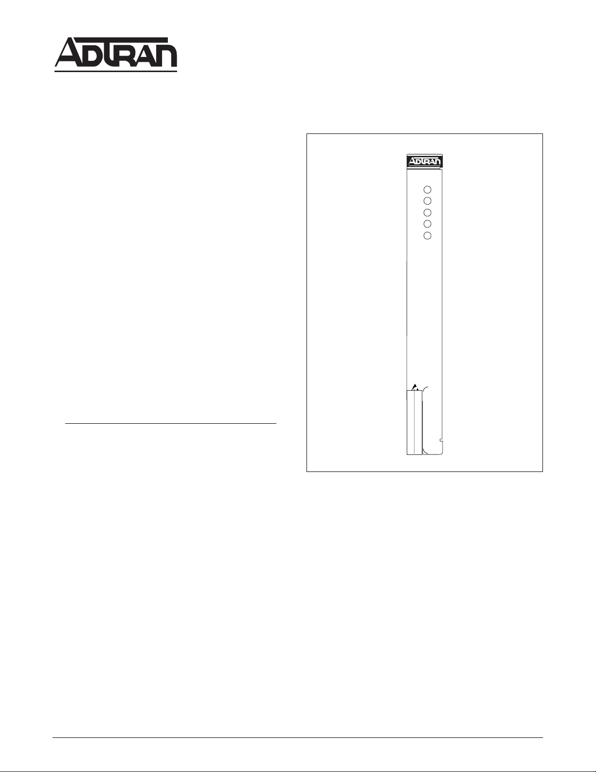
Line Terminating Unit (LTU). Figure 1 illustrates the
SHDSL T1/E1 LTU front panel, P/N 1182210L1.
Revision History
This is the initial issue of this practice. Future changes
to this documentation will be explained in this
subsection.
2. DESCRIPTION
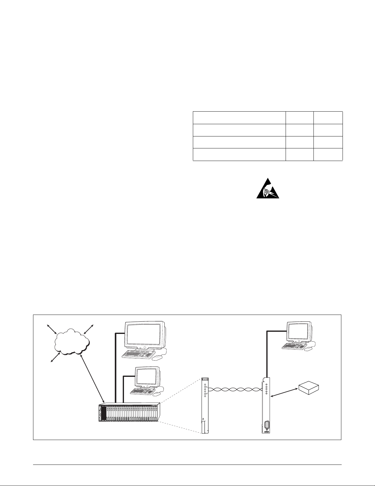
The SHDSL T1/E1 LTU was designed for use in the
Total Access 3000 chassis. The Total Access SHDSL
T1/E1 LTU provides an interface between the SHDSL
network and the Central Office data network. The
SHDSL T1/E1 LTU receives a G.703 signal from the
network and transmits an SHDSL signal to the
customer. The G.703 and SHDSL signals are transmitted/received via the Total Access 3000 chassis
backplane connectors. The SHDSL T1/E1 LTU
supports loop rates from 192 kbps to 2.048 Mbps.
Figure 1. SHDSL T1/E1 LTU Front Panel
The module is 100 percent compliant with the ITU
recommendation (G.991.2) for SHDSL transmission,
ensuring spectral compatibility and interoperability.
Features
The basic features of the SHDSL T1/E1 LTU, P/N
1182210L1, include the following:
• Responds to an Embedded Operations Channel
(EOC) inventory response message
• Provides both transmit and receive clocking
• Provides a user selectable service state option
• Operates in T1 mode with a data rate of 200 kbps to
1.544 Mbps and E1 mode with a data rate of 192
kbps to 2.048 Mbps
• Non-volatile memory configuration
61182210L1-5A 1
Trademarks: Any brand names and product names included in this document are
trademarks, registered tra demarks, or trade names of their respective holders.
Page 2
• Factory default restoration via VT100 menu screens
or SNMP commands
• Firmware upgrade using YModem or TFTP
connection
• Receives remote NTU’s firmware upgrades via
YModem or TFTP connection
• Automatically updates the Circuit ID
• Automatically updates the date and time registers
• Password protected
See Figure 2 for a typical configuration setup.
Connections
The SHDSL T1/E1 LTU inserts into any access module
slot (1 through 28) of a Total Access 3000 chassis.
Power and alarm signals are provided to the module
through the backplane of the chassis.
The G.703 and SHDSL signals are transmitted/received
via the 64-pin backplane amphenol connectors. The
G.703 signal is transmitted to the network side via “Pair
8,” and the G.703 signal is received from the network
side via connector “Pair 7.” The SHDSL signal is transmitted to and from the customer side via connector
“Pair 2.”
1. This device may not cause harmful interference.
2. This device must accept any interference received,
including interference that may cause undesired
operation.
Changes or modifications not expressly approved by
ADTRAN could void the user’s authority to operate this
equipment.
Table 1. Compliance Codes
Code Input Output
Power Code (PC) F C
Telecommunication Code (TC) – X
Installation Code (IC) A –
3. INSTALLATION
C A U T I O N !
SUBJECT TO ELECTROSTATIC DAMAGE
OR DECREASE IN RELIABILITY.
HANDLING PRECAUTIONS REQUIRED.
Compliance
Tab l e 1 shows the compliance codes for the SHDSL T1/
E1 LTU. The SHDSL T1/E1 LTU is NRTL listed to the
applicable UL standards. The SHDSL T1/E1 LTU is to
be installed in a restricted access location and in a Type
“B” or “E” enclosure only.
This device complies with Part 15 of the FCC rules.
Operation is subject to the following two conditions:
Management
Network
SCU
LTU
LTU
LTU
LTU
LTU
LTU
1181018L1
1181308L1
1181308L1
1181308L1
1181308L1
1181308L1
1181308L1
PWR
PWR
PWR
PWR
PWR
PWR
1
1
1
1
1
1
P
P
P
P
P
P
2
2
2
2
2
2
O
O
O
O
O
O
R
R
R
R
R
R
3
3
3
3
3
3
T
T
T
T
T
T
MODE
4
4
4
4
4
4
SELECT
OPT
OPT
OPT
OPT
OPT
OPT
FSE
HST
ALM
ACO
ACO
C
R
A
F
T
1BASCU 2 34 56 78 910 11 12 13 14 15 16 17 18 19 20 21 22 23 24 25 26 27 28
Total Access 3000
System
VT100
LTU
LTU
LTU
LTU
LTU
LTU
LTU
LTU
LTU
LTU
LTU
LTU
LTU
LTU
LTU
LTU
LTU
LTU
LTU
LTU
LTU
LTU
1181308L1
PWR
1
P
2
O
R
3
T
4
OPT
1181308L1
1181308L1
1181308L1
1181308L1
1181308L1
1181308L1
1181308L1
1181308L1
1181308L1
1181308L1
1181308L1
PWR
PWR
PWR
PWR
PWR
PWR
PWR
PWR
PWR
PWR
PWR
1
1
1
1
1
1
1
1
1
1
1
P
P
P
P
P
P
P
P
P
P
2
2
2
2
2
2
2
2
2
2
2
O
O
O
O
O
O
O
O
O
O
R
R
R
R
R
R
R
R
R
R
3
3
3
3
3
3
3
3
3
3
3
T
T
T
T
T
T
T
T
T
T
4
4
4
4
4
4
4
4
4
4
4
OPT
OPT
OPT
OPT
OPT
OPT
OPT
OPT
OPT
OPT
OPT
1181308L1
1181308L1
1181308L1
1181308L1
1181308L1
1181308L1
1181308L1
1181308L1
1181308L1
1181308L1
PWR
PWR
PWR
PWR
PWR
PWR
PWR
PWR
PWR
PWR
1
1
1
1
1
1
1
1
1
1
P
P
P
P
P
P
P
P
P
P
P
2
2
2
2
2
2
2
2
2
2
O
O
O
O
O
O
O
O
O
O
O
R
R
R
R
R
R
R
R
R
R
R
3
3
3
3
3
3
3
3
3
3
T
T
T
T
T
T
T
T
T
T
T
4
4
4
4
4
4
4
4
4
4
OPT
OPT
OPT
OPT
OPT
OPT
OPT
OPT
OPT
OPT
After unpacking the SHDSL T1/E1 LTU, inspect it for
damage. If damage has occurred, file a claim with the
carrier, then contact ADTRAN Customer Service.
Refer to the Warranty and Customer Service section for
further information. If possible, keep the original
shipping container for returning the SHDSL T1/E1
LTU for repair or for verification of shipping damage.
VT100
SHDSL
NTU
T1/E1
NTU
1225236L1
PWR
SHDSL
T1/E1
TEST
ALM
Customer T1 or E1
Equipment
(e.g., PABX)
LTU
1181308L1
2-Wire Twisted Pair
PWR
1
P
2
O
R
3
T
4
OPT
SHDSL
T1/E1
LTU
SHDSL
Figure 2. Typical System Application
2 Issue 1, August 2003 61182210L1-5A
Page 3

Shipping Contents
The contents include the following items:
• SHDSL T1/E1 LTU
• SHDSL T1/E1 LTU Installation and Maintenance
Practice
CAUTION
Electronic modules can be damaged by ESD.
When handling modules, wear an antistatic
discharge wrist strap to prevent damage to
electronic components. Place modules in
antistatic packing material when transporting
or storing. When working on modules, always
place them on an approved antistatic mat that is
electrically grounded.
Instructions for Installing the Module
The SHDSL T1/E1 LTU inserts into any access module
slot (1 through 28) of a Total Access 3000 chassis. To
install the SHDSL T1/E1 LTU, perform the following
steps:
1. If present, remove the Access Module Blank (P/N
1181953L1) from the appropriate access module
slot of the Total Access 3000 chassis.
2. Hold the unit by the front panel while supporting
the bottom side with the ejector latch at the bottom,
and the latch opened to engage the chassis edge
when it is plugged in.
3. Align the module edges to fit in the lower and
upper guide grooves for the designated slot.
4. Slide the module into the access module slot while
pressing equally on the top and bottom of the front
panel until the module is firmly positioned against
the backplane of the chassis.
5. Lock the module in place by pushing in on the
locking lever located on the lower left-hand side of
the module.
The SHDSL T1/E1 LTU initializes and goes operational upon insertion into an active Total Access 3000
chassis. Initialization is indicated by the front panel
LEDs.
LED Indicators
The front panel of the SHDSL T1/E1 LTU has five LED
status indicators. Table 2 lists the LED descriptions.
Table 2. Front Panel LEDs
LED Indication Description
PWR Off
Green
Ye ll ow
SHDSL Off
Green
Ye ll ow
T1/E1 Off
Green
TEST Off
Green
Ye ll ow
ALM Off
Ye ll ow
The module is powered off
The module is In Service
The module is Out of Service or in the process of a firmware upgrade
SHDSL loop is Out of Service, Unassigned
SHDSL loop is trained with good signal quality
SHDSL loop is trained with poor signal quality
SHDSL loop is not trained
Red
Port is active with alarms
Port is active with no alarms
Module is not in loopback or BERT
Local loopback is active or BERT is running with no errors
BERT is running with bit errors
BERT is running with no pattern sync
Red
No alarm condition detected
Alarm condition detected remotely
Red
Alarm condition detected locally
61182210L1-5A Issue 1, August 2003 3
Page 4

4. PROVISIONING
All provisioning will be handled through the SCU
communication link, either through the menu access or
SNMP. There are no onboard DIP switches or jumpers.
The unit will retain provisioning data in a nonvolatile
memory device in case of a loss of power to the module.
NOTE
To ensure proper display background, select
VT100 terminal emulation under
Settings
.
Total Access 3000 system management and provisioning is facilitated by a series of intuitive menus that
are accessible on a computer screen. Connecting either
a VT100 terminal or a PC emulating a VT100 terminal
to the craft interface on the SCU front panel allows
access to the menus and management features of the
Total Access 3000.
The front craft access port for the Total Access 3000
system is located on the front panel of the SCU and is a
DB-9 connector. Access can also be made to the Total
Access 3000 chassis from the backplane through the
port labeled
ADMIN (J31). It is a DB-25 connector, and
is located on the upper right corner of the backplane.
NOTE
Connecting to the Total Access 3000 chassis
from the front craft port on the SCU requires a
straight serial data cable. Connection to the
Total Access 3000 chassis via the rear
connector on the backplane requires the use of
a null modem cable, because that port is
configured for a modem and expects to see
DCE equipment.
Password and User ID
Password protection is factory enabled. If password
protection is enabled, the SCU will display the logon
screen, and a valid account name and password are
required to access menus. The factory default account
names and default passwords (both are case sensitive)
are displayed in Ta b le 3.
Table 3. Account Names and Passwords
Account
Name
ADMIN PASSWORD Administration Access
READONLY PASSWORD Read Access only
READWRITE PASSWORD Read and Write
TEST PASSWORD Read and Test Access
Default
Password
Access
Rights
Access
NOTE
The Account Name and Password are to be
entered in all capital letters.
The parameters of the VT100 terminal should be set as
follows:
• 9600 Baud
• No parity
• 8 Data bits
• 1 Stop bits
Menu Navigation
The following subsection describes the SHDSL T1/E1
LTU menus. Most menu selections are made by typing
the corresponding number and then pressing
the wrong selection is made, pressing
SC
E
the previous screen. The Question Mark (
NTER
E
will display
) can be used
?
. If
at any time to display a list of menu commands.
• No Flow Control
Main Menu
Windows HyperTerminal
Windows HyperTerminal can be used as a VT100
terminal emulation program. Open HyperTerminal by
selecting
to the
Help
Programs/Accessories/HyperTerminal
section of HyperTerminal for additional
. Refer
information.
The Total Access Main menu allows the user to access
the module for various functions such as provisioning,
status, alarms, and performance monitoring.
The menu tree in Figure 3 illustrates the path to every
provisioning, performance, and test access point in the
SHDSL T1/E1 menu system.
Tab l e 4 lists the complete set of configurable options
with settings and factory default values.
4 Issue 1, August 2003 61182210L1-5A
Page 5

NOTE
When the LTU is in T1 mode, all related E1
options will be non-applicable. A non-applicable option setting is still changeable, but will
not take affect until the option become applicable.
5. OPERATION
Test Capabilities
The Total Access SHDSL T1/E1 LTU has the following
test capabilities:
• Self diagnostics
• Local loopbacks
• EOC initiated remote loopbacks
• Internal bit error rate tester (BERT)
Customer Port
The SHDSL T1/E1 LTU operates in either E1 mode or
T1 mode.
E1 Mode
In E1 mode the port features are as follows:
• Carries information at the rate of 2.048 Mbps
• Uses CCS framed format with or without CRC-4
• Operates in either Alternate Mark Inversion (AMI)
or High-Density Bipolar 3 (HDB3) line code
• Provides programmable timeslot idle pattern
• Supports ISDN-PRA V3 service
• Displays additional status information via a local
VT100 management screen
See Tab le 5 for E1 port statistics definitions.
T1 Mode
In T1 mode the port features are as follows:
Self Diagnostics
The Total Access SHDSL T1/E1 LTU performs self
diagnostic tests of its Read Only Memory (ROM),
Random Access Memory (RAM), LEDs, and nonvolatile configuration setting upon power-up.
Local and Remote Loopbacks
For troubleshooting purposes, the SHDSL T1/E1 LTU
provides three types of loopback tests.
1. Dual sided
2. Network
3. Customer
BERT
The SHDSL T1/E1 LTU provides an internal bit error
rate tester (BERT) for the injection and observation of
random bit sequence to and from the SHDSL.
• Carries information at the rate of 1.544 Mbps
• Uses Superframe Format (SF) or Extended Superframe Format (ESF)
• Operates in either Alternate Mark Inversion (AMI)
or Bipolar w/8-Zero Substitution (B8ZS) line code
• Provides programmable timeslot idle pattern
• Monitors the Facility Data Link (FDL)
• Displays additional status information via a local
VT100 management screen
See Tab le 6 for T1 port statistics definitions.
NOTE
In T1 mode both the SHDSL T1/E1 LTU and
the SHDSL NTU must be operational.
61182210L1-5A Issue 1, August 2003 5
Page 6

6 Issue 1, August 2003 61182210L1-5A
Main
Menu
1. Unit Information
1. Unit Options
2. Provisioning
2. SHDSL Options
3.
4. Test Options
3. Status
4. Test
5. Performance History
6. Terminal Mode
1. SHDSL = ALARMS
2. E1 = ALARMS
1. Local Loopback
2. Remote Loopback
3. BERT
1. LTU
2. NTU
1. E1 Options
2. T1 Options
1. Data Mode = E1, Timeslots
2. Local Management = Enabled
3. Clock Source = Internal
4. Service State = In Service
5. Ext Port Alarms = Enabled
6. Circuit ID
7. Restore Factory Defaults
8. Upgrade Firmware
9. Change Password
1. SES Count Threshold = 50 CVCs
2. SNR Margin Alarm Threshold = Disabled
3. Loop Attenuation Alarm Threshold = Disabled
4. ES 15 Minute Alarm Threshold = Disabled
5. SES 15 Minute Alarm Threshold = Disabled
6. UAS 15 Minute Alarm Threshold = Disabled
7. CVC 15 Minute Alarm Threshold = Disabled
8. LOSWS 15 Minute Alarm Threshold = Disabled
1. DSX-1 Line Buildout
2. Line Coding
3. Framing Mode
4. Idle Pattern
5. FDL Monitoring
1. Loopback Time Out = Disabled
2. BERT Pattern = 2e15-1
3. BERT Pattern Polarity = Normal
1. SHDSL
2. E1
1. AMI
2. HDB3
1. Disabled
2. Enabled
1. Dual Sided
2. Customer
3. Network
4. Off
1. Internal
2. External
1. Disabled
2. Enabled
1.-255. CVCs to cause a SES
1. 0-133 Feet
2. 133-266 Feet
3. 266-399 Feet
4. 399-533 Feet
5. 533-655 Feet
1. Unframed
2. SF
3. ESF
1. Normal
2. Inverted
1. Data Type = E1
1. Disabled
2. Enabled
1. In Service
2. Out of Service - Unassigned
3. Out of Service - Maintenance
0. Disabled
1-15. Threshold in dB
0. Disabled
1-127. Threshold in dB
0. Disabled
1-65535. Errors
0. Disabled
1-999. Timeout in Minutes
1. ALT
2. 2047
3. 2e15-1
4. QRSS
2. Data Rate = 3
3. Apply Settings
0. Disabled
1-900. Seconds
1. Line Coding = HDB3
2. Framing Mode = CCS
3. ISDN-PRA V3 = Disabled
4. Idle Pattern = FFh
General Status
Data Rate
Framing Mode
Errored Seconds (ES)
Severely Errored Seconds (SES)
Unavailable Seconds (UAS)
Code Violations Count (CVC)
Transmit Customer Alarm Indication Signal (Tx Cust AIS)
Transmit Network Alarm Indication Signal (Tx Net AIS)
Customer Source Address Bits (Cust SA -Bits)
Network Source Address Bits (Net SAS-Bits)
Network Address Bit (Net A-Bit)
SHDSL Version
Vendor List Number
Vendor Issue Number
Vendor Software Version
Unit Identification Code (CLEI)
Vendor ID
Vendor Model Number
Vendor Serial Number
Manufacture Date
PROM Check Sum
SHDSL Version
Vendor List Number
Vendor Issue Number
Vendor Software Version
Unit Identification Code (CLEI)
Vendor ID
Vendor Model Number
Vendor Serial Number
Other Vendor Information
1. AMI
2. HDB3
General Status
Aggregate Rate (kbps)
SNR Margin (dB) (Cur/Min/Max)
Loop Attenuation (dB) (Cur/Min/Max)
Errored Seconds (ES)
Severely Errored Seconds (SES)
Unavailable Seconds (UAS)
Code Violations Count (CVC)
LOSW Seconds (LOSWS)
Loopback Status
BERT Status
1. Unframed
2. CCS
3. CCS w/CRCA
1. Disabled
2. Enabled
Figure 3. SHDSL T1/E1 LTU Menu Tree
Page 7

Table 4. Configuration Options List
Category Option Setting Default
Unit Options Data Mode For Data Type = T1, Data Rate can
be from 3 to 24 timeslots
(i.e. 200 kbps to 1.544 Mbps)
For Data Type = E1, Data Rate can
be from 3 to 32 timeslots
(i.e., 192 kbps to 2.048 Mbps)
Local Management 1 = Disabled
2 = Enabled
Clock Source 1 = Internal
2 = External
Service State 1 = In Service
2 = Out of Service - Unassigned
3 = Out of Service - Maintenance
External Port Alarms 1 = Disabled
2 = Enabled
Restore Factory Defaults
Firmware Upgrade
Change Password
SHDSL Options SES CVC Threshold 0 to 255 CVC’s 50
Data Type = 1
Data Rate = 24
Enabled
Internal
Out of Service Maintenance
Disabled
SNR Margin Alarm
Threshold
Loop Attenuation Alarm
Threshold
ES 15 Minute Alarm
Threshold
SES 15 Minute Alarm
Threshold
UAS 15 Minute Alarm
Threshold
CVC 15 Minute Alarm
Threshold
LOSWS 15 Minute Alarm
Threshold
T1 Options (T1 Mode Only) Line Coding 1 = AMI
Framing Mode 1 = Unframed
0 = Disabled
1 to 15db = Alarm Threshold
0 = Disabled
1 to 127db = Alarm Threshold
0 = Disabled
1 to 900 Seconds = Alarm Threshold
0 = Disabled
1 to 900 Seconds = Alarm Threshold
0 = Disabled
1 to 900 Seconds = Alarm Threshold
0 = Disabled
1 to 65535 Errors = Alarm threshold
0 = Disabled
1 to 900 Seconds = Alarm Threshold
2 = B8ZS
2 = SF
3 = ESF
Disabled
Disabled
Disabled
Disabled
Disabled
Disabled
Disabled
B8ZS
ESF
Idle Pattern 00h to FFh 7Fh
FDL Monitoring (ESF Mode
Only)
61182210L1-5A Issue 1, August 2003 7
1 = Disabled
2 = Enabled
Disabled
Page 8

Table 4. Configuration Options List (Continued)
Category Option Setting Default
E1 Options (E1 Mode Only) Line Coding 1 = AMI
2 = HDB3
Framing Mode 1 = Unframed
2 = CCS
3 = CCS w/CRC-4
Idle Pattern 00h to FFh FFh
ISDN - PRA V3 (CCS or
CCS w/CRC-4 Mode Only)
Test options Loopback Timeout 0 = Disabled
BERT Pattern 1 = ALT
BERT Pattern Polarity 1 = Normal
1 = Disabled
2 = Enabled
1 to 999 Minutes = Timeout
2 + 2047
3 = 2e15 – 1
4 = QRSS
2 = Inverted
Table 5. E1 Port Statistics Definitions
HDB3
CCS
Disabled
Disabled
2e15 – 1
Normal
Statistic Framing Mode Definition
Errored Seconds (ES) Unframed LOS condition or BPV’s > 0
CCS LOS or LOF condition, or if BPV’s > or FE’s > 0
CCS w/CRC-4 LOS, LOF, or LOMFA condition, or if FE’s > 0 or CRC-4
errors > 0
Severely Errored Seconds (SVS) Unframed LOS condition
CCS LOS or LOF condition or if FE’s > 4
CCS w/CRC-4 LOS, LOF, or LOMFA condition, or if FE’s > 4 or CRC-4
errors ≥
Unavailable Seconds (UAV) N/A If 10 continuous SES’s, then UAS
If 10 continuous seconds with no SES’s, then no UAS
Code Violations Count (CVC) Unframed If BPV’s > 0
CCS If BPV’s > 0, or FE’s > 0
CCS w/CRC-4 If FE’s > 0 or CRC-4 errors > 0
300
8 Issue 1, August 2003 61182210L1-5A
Page 9

Table 6. T1 Port Statistics Definitions
Statistic Framing Mode Definition
Errored Seconds (ES) Unframed LOS condition or BPV’s > 0
SF LOS or LOF condition, or if BPV’s > 0 or FE’s > 0
ESF LOS or LOF condition, or if BPV’s > 0 or FE’s > 0
Severely Errored Seconds (SVS) Unframed LOS condition or BPV’s > 1544
SF LOS or LOF condition, or if BPV’s > 1544 or if FE’s > 8
ESF LOS or LOF condition, or if BPV’s > 1544 or if FE’s > 8
Unavailable Seconds (UAV) N/A If 10 continuous SES’s, then UAS
If 10 continuous seconds with no SES’s, then no UAS
Code Violations Count (CVC) Unframed If BPV’s > 0
SF If BPV’s > 0 or FE’s > 0
ESF If BPV’s > 0 or FE’s > 0
Table 7. SHDSL T1/E1 LTU Specifications
6. MAINTENANCE
The SHDSL T1/E1 LTU requires no routine maintenance for normal operation.
ADTRAN does not recommend that repairs be
attempted in the field. Repair services may be obtained
by returning the defective unit to ADTRAN. Refer to
the Warranty and Customer Service section for further
information.
Operating Temperature:
Storage Temperature:
Relative Humidity:
Environmental
–5°C to 55°C
–40°C to 85°C
90 percent maximum @
50°C, noncondensing
7. SPECIFICATIONS
Specifications for the Total Access 3000 SHDSL T1/E1
LTU are detailed in Tabl e 7 .
8. WARRANTY AND CUSTOMER SERVICE
ADTRAN will replace or repair this product within the
warranty period if it does not meet its published specifications or fails while in service. Warranty information
can be found at www.adtran.com/warranty
.
Maximum Current Draw:
Maximum Heat
Dissipation:
Physical
Dimensions:
Weight:
Part Number
SHDSL T1/E1 LTU
Module:
0.15 A maximum
@ Ð48 VDC
3.5 watts
6 in. H x .625 in. W x 10
in. D
< 1 lb.
1182210L1
61182210L1-5A Issue 1, August 2003 9
Page 10

10 Issue 1, August 2003 61182210L1-5A
 Loading...