


AAW-08DM1FHU
Admiral AAW-08DM1FHU, AAW-O6CM1FHU, AAW-08CR1FHU, AAW-05CM1FHU, AAW-08DR1FHU User Manual
...
Thank you for purchasing an Admiral®room air conditioner. Please read this “Use and Care Manual” carefully
before installing and using this appliance. Keep this manual for future reference.
Muchase gracias por comprar un aire acondicionado Admiral
®
. Lea atentamente el “Manual de Uso y
Mantenimiento” antes de instalar y utilizar este producto. Conserve este manual para consultarlo en el futuro.
For Service Call 1 877 465 3566
Para obtener servicio técnico, llame al 1 877 465 3566
ROOM AIR CONDITIONER
Use and Care Manual
AIRE ACONDICIONADO PARA HABITACIONES
Manual de Uso y Mantenimiento
WAC 5 6 8 USER MAN final 3/2/05 12:23 PM Page 1

WAC 5 6 8 USER MAN final 3/2/05 12:23 PM Page 2

1
TABLE OF CONTENTS
Page
Introduction . . . . . . . . . . . . . . . . . . . . . . . . . . . . . . . . . . . . . . . . . . . . . . . . . . 2
Parts Identification . . . . . . . . . . . . . . . . . . . . . . . . . . . . . . . . . . . . . . . . . . . 2-3
Air Conditioner Safety . . . . . . . . . . . . . . . . . . . . . . . . . . . . . . . . . . . . . . . . . 4-5
Electrical Specifications . . . . . . . . . . . . . . . . . . . . . . . . . . . . . . . . . . . . . . . . .6
Tips Before Installation . . . . . . . . . . . . . . . . . . . . . . . . . . . . . . . . . . . . . . . . . 7
Installation Instructions . . . . . . . . . . . . . . . . . . . . . . . . . . . . . . . . . . . . . . 8-10
Operating Instructions . . . . . . . . . . . . . . . . . . . . . . . . . . . . . . . . . . . . . . 11-14
Care and Maintenance . . . . . . . . . . . . . . . . . . . . . . . . . . . . . . . . . . . . . . . . . 15
Troubleshooting Guide . . . . . . . . . . . . . . . . . . . . . . . . . . . . . . . . . . . . . . . . . 16
Warranty . . . . . . . . . . . . . . . . . . . . . . . . . . . . . . . . . . . . . . . . . . . . . . . . . . . 17
I´NDICE
Page
Introducción . . . . . . . . . . . . . . . . . . . . . . . . . . . . . . . . . . . . . . . . . . . . . . . . . 18
Identificación de las Piezas . . . . . . . . . . . . . . . . . . . . . . . . . . . . . . . . . . 18-19
Especificaciones Eléctricas . . . . . . . . . . . . . . . . . . . . . . . . . . . . . . . . . . . . . 20
Consejos Antes dela Instalación . . . . . . . . . . . . . . . . . . . . . . . . . . . . . . . . . . 21
Instrucciones de Instalación . . . . . . . . . . . . . . . . . . . . . . . . . . . . . . . . . . 22-24
Instrucciones de Operación . . . . . . . . . . . . . . . . . . . . . . . . . . . . . . . . . . 25-28
Cuidado y Mantenimiento . . . . . . . . . . . . . . . . . . . . . . . . . . . . . . . . . . . . . . . 29
Guía para la Solución de Problemas . . . . . . . . . . . . . . . . . . . . . . . . . . . . . . . 30
Garantía . . . . . . . . . . . . . . . . . . . . . . . . . . . . . . . . . . . . . . . . . . . . . . . . . . . . 31
WAC 5 6 8 USER MAN final 3/2/05 12:23 PM Page 3
INTRODUCTION
2
➤PART IDENTIFICATION
WAC 5 6 8 USER MAN final 3/2/05 12:23 PM Page 4
Thank you for choosing this room air conditioner to cool your home. This USE AND CARE MANUAL
provides information necessary for the proper care and maintenance of your new room air conditioner.
If properly maintained, your air conditioner will give you many years of trouble free operation. To avoid
installation difficulties, read instructions completely before starting. This manual contains information for the
installation and operation of your room air conditioner.
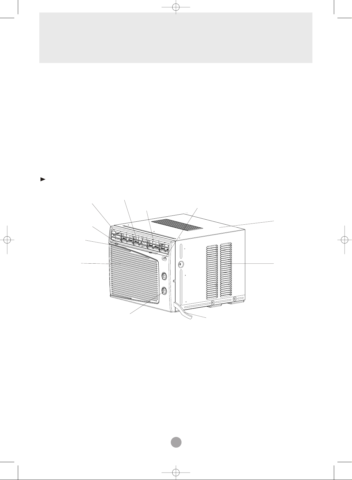
Part Identification
Mechanical control model
Interior Air Outlet
Air Filter(Inside)
Front Panel
Interior Air
Inlet Grille
Note:
The figures in this manual are based on the external view of a standard model.
Consequently, the shape may differ from that of the air conditioner you have selected.
Horizontal Air Vane
Vertical Air Vane
Control Knob
Fresh Air Lever (for 8K model only)
Power Cord
Cabinet
Exterior
Air Inlet
INTRODUCTION
3
➤PART IDENTIFICATION
WAC 5 6 8 USER MAN final 3/2/05 12:23 PM Page 5
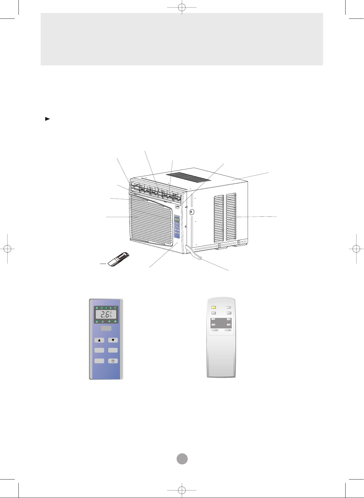
Part Identification
Remote control model
Interior Air Outlet
Air Filter(Inside)
Front Panel
Interior Air
Inlet Grille
Remote Control
Control Panel
Horizontal Air Vane
Control Panel
Vertical Air Vane
T
im
er
F
an
M
ode
Airc
ondition
er
Fresh Air Lever (for 8K model only)
Power Cord
Remote Control
Power
Timer
Power Sa ver
Mode
Mid
Auto
Fan Speed
High Low
_
+
Temp/Time
Cabinet
Exterior
Air Inlet
Fan
Timer
Speed
Mode
Airconditioner
Note:
The figures in this manual are based on the external view of a standard model.
Consequently, the shape may differ from that of the air conditioner you have selected.

4
AIR CONDITIONER SAFETY
Your safety and the safety of others are very important.
We have provided many important safety messages in this manual and on your appliance. Always read and obey
all safety messages.
This is the SAFETY ALERT SYMBOL.
This symbol alerts you to potential hazards that can kill or hurt you and others.
All safety messages will follow the safety alert symbol and either the word “DANGER” or
“WARNING.” These words mean:
You can be killed or seriously inured if you don’t
immediately
follow instructions.
You can be killed or seriously inured if you
don’t follow instructions.
All safety messages will tell you what the potential hazard is, tell you how to reduce the chance of injury, and tell
you what can happen if the instructions are not followed.
IMPORTANT SAFETY INSTRUCTIONS
WARNING: To reduce the risk of fire, electrical shock, or
injury when using your air conditioner, follow these basic
precautions:
• Plug into a grounded 3-prong outlet. • Do not use an extension cord.
• Do not remove ground prong. • Unplug air conditioning before
servicing.
• Do not use an adapter. • Use two or more people to
move and install air conditioner.
—SAVE THESE INSTRUCTIONS —
WAC 5 6 8 USER MAN final 3/2/05 12:23 PM Page 6
5
INSTALLATION REQUIREMENTS
INSTALLATION INSTRUCTIONS
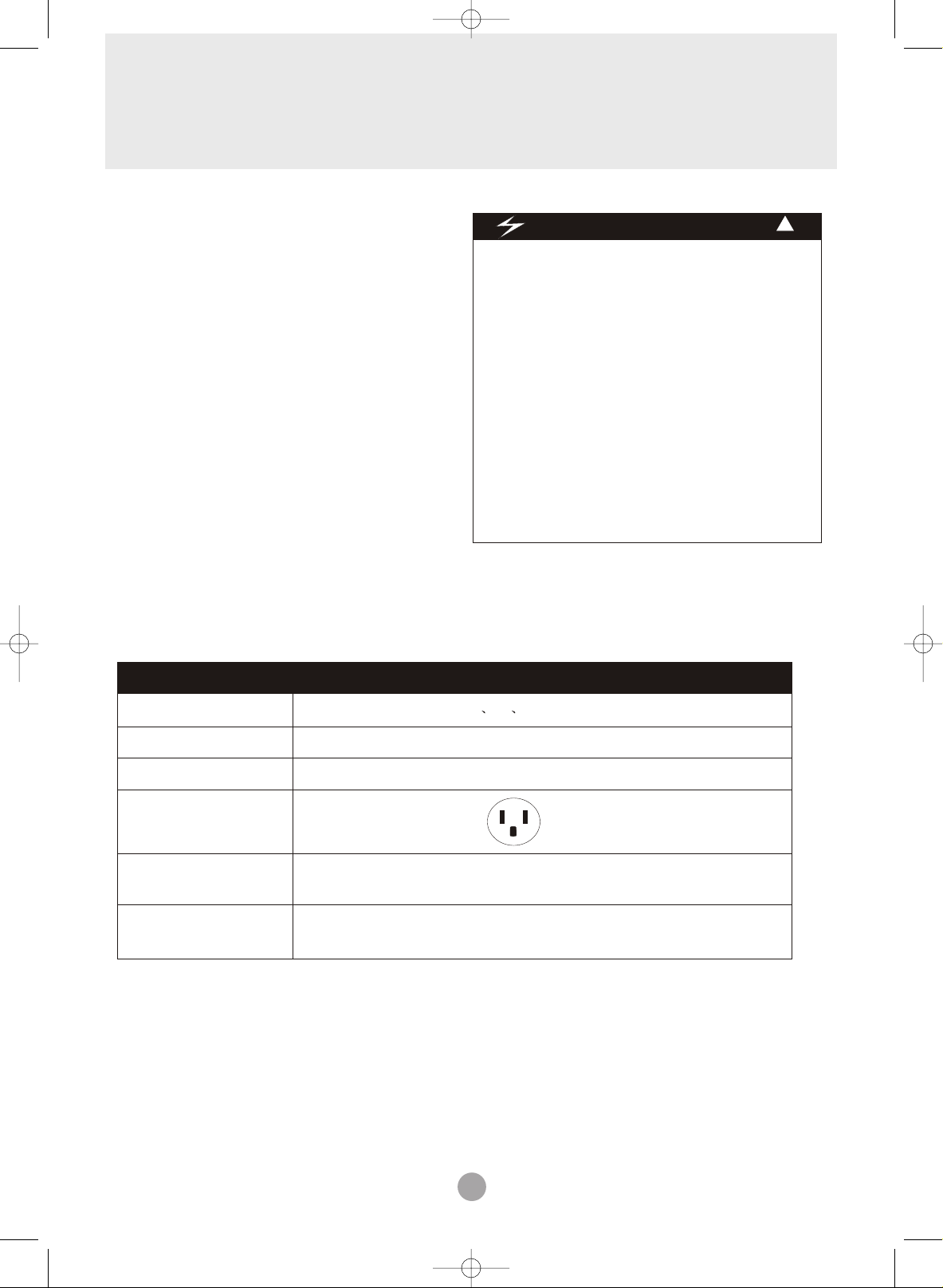
Electrical Requirements
ELECTRIC SHOCK HAZARD
• Plug into a grounded 3-prong outlet.
• Do not remove ground prong.
• Do not use an adapter.
• Do not use an extension cord.
• Failure to follow these instructions can
result in death, fire, or electrical shock.
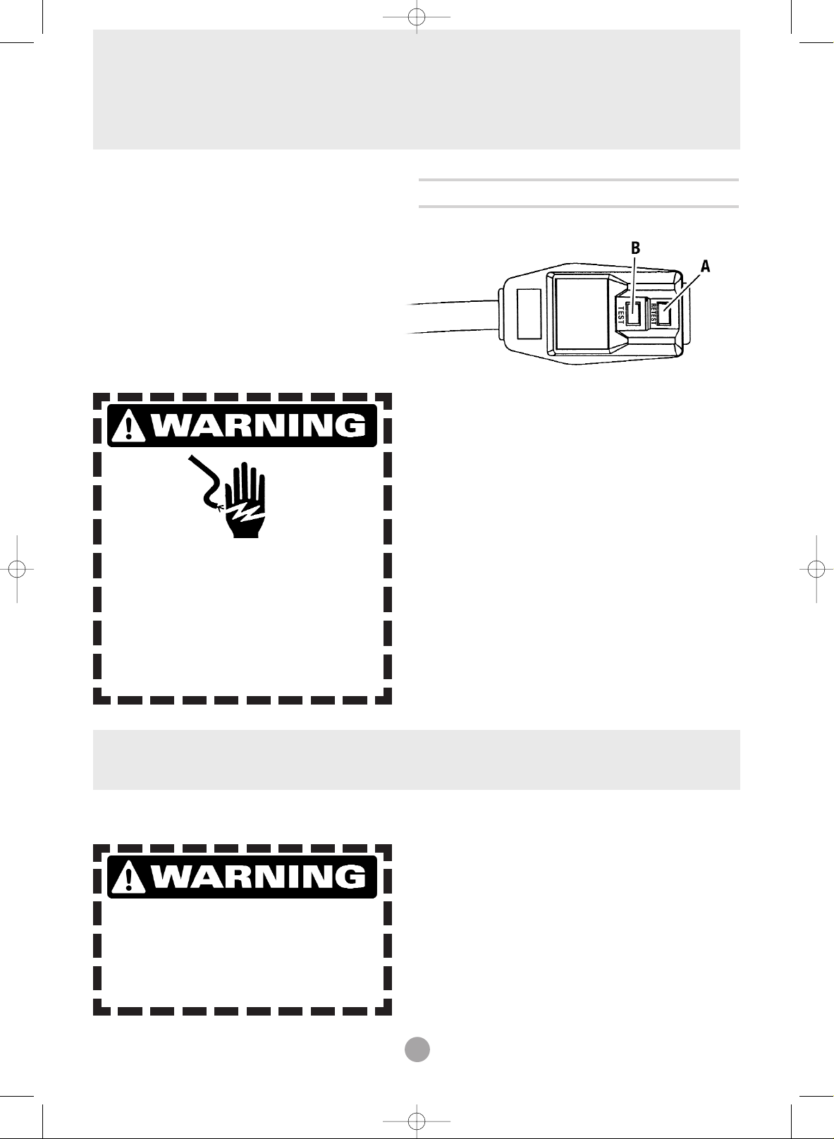
Power Supply Cord
NOTE: Your unit’s device may differ from the one shown.
Unpack the Air Conditioner
EXCESSIVE WEIGHT HAZARD
Use two or more people to move and
install air conditioner.
Failure to do so can result in back or
other injury.
Remove packaging materials
• Remove and properly dispose of packaging materials.
Remove tape and glue residue from surfaces before
turning on the air conditioner. Rub a small amount
of liquid dish soap over the adhesive with your fingers.
Wipe with warm water and dry.
• Do not use sharp instruments, rubbing alcohol,
flammable fluids, or abrasive cleaners to remove
tape or glue. These products can damage the
surface of your air conditioner.
• Handle air conditioner with care.
• The portable air conditioner should be connected
to a 115 V, 60 Hz, 15- or 20-amp fused 3-prong
grounded outlet.
• The use of a time-delay fuse or time-delay circuit
breaker is recommended.
• All wiring must comply with local and national
electrical codes and be installed by a qualified
electrician. If you have any questions, contact
a qualified electrician.
A Reset Button B Test Button
This room air conditioner is equipped with a power supply cord required
by UL. This power supply cord contains state-of-the-art electronics that
sense leakage current. If the cord is crushed, the electronics detect leakage
current and power will be disconnected in a fraction of a second.
To test your power supply cord:
1. Plug power supply cord into a grounded 3-prong outlet.
2. Press RESET.
3. Press TEST (listen for click; Reset button will trip and pop out).
4. Press and release RESET (listen for click; Reset button will latch
and remain in).The power supply cord is ready for operation.
NOTES:
• The Reset button must be pushed in for proper operation.
• The power supply cord must be replaced if it fails to trip when the
test button is pressed or fails to rest.
• Do not use the power supply cord as as an off/on switch. The
power supply cord is designed as a protective device.
• A damaged power supply cord must be replaced with a new power
supply cord obtained from the product manufacturer and must not
be repaired.
• The power supply cord contains no use serviceable parts. Opening
the tamper-resistant case voids all warranty and performance claims.
WAC 5 6 8 USER MAN final 3/2/05 12:23 PM Page 7
6
ELECTRICAL SPECIFICATIONS
WAC 5 6 8 USER MAN final 3/2/05 12:23 PM Page 8
1. All wiring must comply with local and national
electrical codes and must be installed by a
licensed electrician. Once you have any
questions regarding the following instructions,
contact a licensed electrician.
2. Check available power supply and resolve any
wiring problems BEFORE installing and operating
this unit.
3. For your safety and protection, this unit is
grounded through the power cord when
plugged into a matching wall outlet. If you are
not sure whether your wall outlet is properly
grounded, please consult a licensed
electrician.
4. The wall outlet(3-pin) must match the plug
(3-pin) on the power cord supplied with the unit.
DO NOT use plug adapters or extension cords.
See (Table 1) for receptacle and fuse information.
Electric Shock Hazard
!
If the air conditioner has a serial plate rating
of 115 volts and up to and including 7.5 amps
the unit maybe on a fuse or circuit breaker
with other devices. However, the maximum
amps of all devices on that fuse or circuit
breaker can not exceed the amps of the fuse
of circuit breaker.
If the air conditioner has a serial plate rating
of 115 volts and greater than 7.5 amps it
must have its own fuse or circuit breaker,
and no other device or unit should be
operated on the fuse or circuit breaker.
To avoid the possibility of personal injury,
disconnect the power to the unit before
installing or servicing.
5. The rating plate on the unit contains electrical
and other technical data. The rating plate is located
on the right side of the unit.
RECEPTACLE AND FUSE TYPES
COOLING CAPACITY
RATED VOLTS
AMPS
WALL OUTLET
FUSE SIZE
Time Delay Fuse
(or circuit breaker)
Note: 5K including
6K including
8K including
AAW-05CR1FHU
AAW-06CR1FHU
AAW-08CR1FHU
AAW-08CM1FHU
5K 6K 8K
125
15
15
Plug type
Table 1
AAW-05CM1FHU
AAW-06CM1FHU
AAW-08DR1FHU
AAW-08DM1FHU
7
TIPS BEFORE INSTALLATION
WAC 5 6 8 USER MAN final 3/2/05 12:23 PM Page 9
Your Room Air Conditioner unit is designed to
be highly efficient and save energy. Follow these
recommendations for greater efficiency.
1. Select thermostat setting that suits your
comfort needs and leave the thermostat at
that chosen setting.
2. The air filter is very efficient in removing airborne
particles. Keep the air filter clean. Typically, filter
should be cleaned once a month. More
frequent cleaning may be necessary depending
on outdoor and indoor air quality.
3. Use drapes, curtains, or shades to keep
direct sunlight from heating your room, but
DO NOT obstruct the air conditioner. Allow air to
circulate around the unit without obstructions.
4. Start your air conditioner before outdoor
air becomes hot and uncomfortable. This
avoids an initial period of discomfort while
the unit is cooling off the room.
5. When outdoor temperature is cool
enough, use HIGH or LOW FAN
only. This circulates indoor air, providing
some cooling comfort, and utilizes less
electricity than when operating on a
cooling setting.
Your Room Air Conditioner was designed
for easy installation in a single or double-hung
window. NOTE: This unit is NOT designed for
vertical (slider type) windows.
! !
To avoid installation/operating difficulties,
read the instructions thoroughly.
NOTE: Save the shipping carton and packing
materials for future storage or transport of the unit.
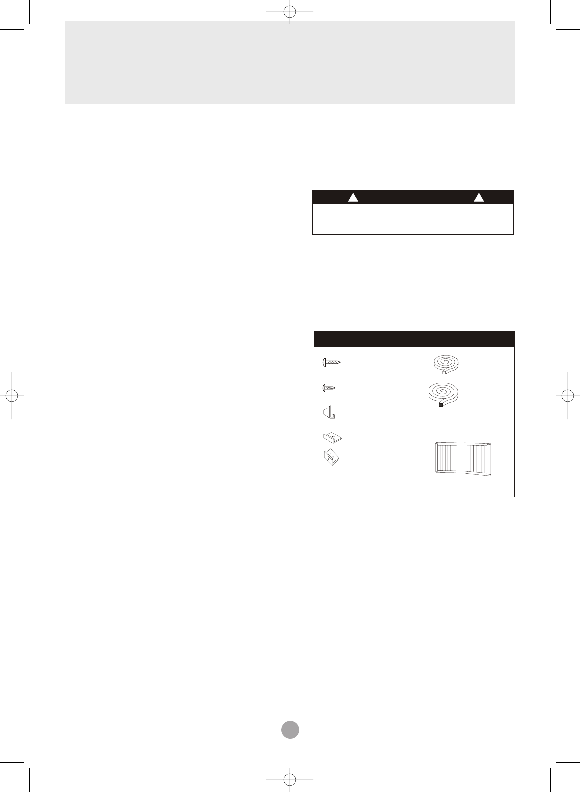
Please check the contents of the hardware kit
against the corresponding model check list, prior to
installation of the unit.
See lists below.(Fig.1)
3/4"Screws (12)
2/5"Screws (8)
Top Channel(1)
factory installed
L Bracket(2)
Side Bracket(2)
NOTE: Surplus screw(s) for spare use.
Tools Needed for Window Installation
Screw drivers: Both Philips and flat head
Power drill: 1/8 inch diameter drill bit
Pencil
Measuring tape
Scissors
Carpenters level
CAUTION
Installation Hardware
Seal(1)
Foam(1)
Side Curtain RH(1)
Side Curtain LH(1)
Fig.1
8
INSTALLATION INSTRUCTIONS
B. Make sure the window and frame are structurally
sound and free from dry, rotted wood.
WAC 5 6 8 USER MAN final 3/2/05 12:23 PM Page 10
! !
Because the compressor is located on the
controls side of the unit (right side), this side
will be heavier and more awkward to manipulate.
Inadequate support on control side of the unit
can result in personal injury and damage to your
unit and property. Therefore, it is recommended
to have someone assist you during the installation
of this unit.
1. Select the Best Location
A. Your room air conditioner was designed to
fit easily into a single or double hung window. However,
since window designs vary, it may be necessary to
make some modifications for safe and proper
installation.
B. Make sure the window and frame are structurally
sound and free from dry and rotted wood.
C. For maximum efficiency, install the air conditioner
on side of the house or building which favors more
shade than sunlight. If the unit is in direct sunlight,
it is advisable to provide an awning over the unit.
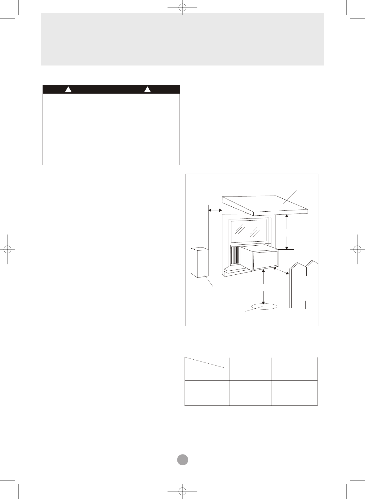
D. Provide sufficient clearance around the cabinet
to allow for ample air circulation through the unit.
See (Fig.2). The rear of the unit should be outdoors
and not in a garage nor inside of a building.
Keep unit as far away as possible from obstacles
and obstructions and at least 30" above the floor or
ground. Curtains and other objects within a room
should be prevented from blocking the air flow.
E. Be certain the proper electrical outlet is within reach
of the installation. Use only a single outlet circuit rated
at 15 amps. All wiring should be in accordance with
local and national electrical codes.
.
CAUTION
F. Your unit was designed to evaporate condensation
under normal conditions. However, under extreme
humidity conditions, excess condensation may cause
the base pan to overflow to the outside.
The unit should be installed where condensation
run-off cannot drip on pedestrians or neighboring
properties.
Awning
20"
Min.
12" Min.
20"
Min.
Fence,
Side
obstruction
Ground
Window opening requirements
(see table below)
SizeSize
ModelModel 5K-6K5K-6K
Cabinet size
Cabinet size
(W*H*D)
(W*H*D)
Min. Window
Min. Window
opening
opening
Max. Window
Max. Window
opening
opening
17.7" *12.4" *15.7" 17.7" *12.4" *15.7"
30" Min.
Fig.2
21" 21"
35" 35"
18.5" *13.7" *17.7" 18.5" *13.7" *17.7"
wall, or
other
obstacle.
8K 8K
22" 22"
36" 36"
9
INSTALLATION INSTRUCTIONS
➤WINDOW INSTALLATION STEP
WAC 5 6 8 USER MAN final 3/2/05 12:23 PM Page 11
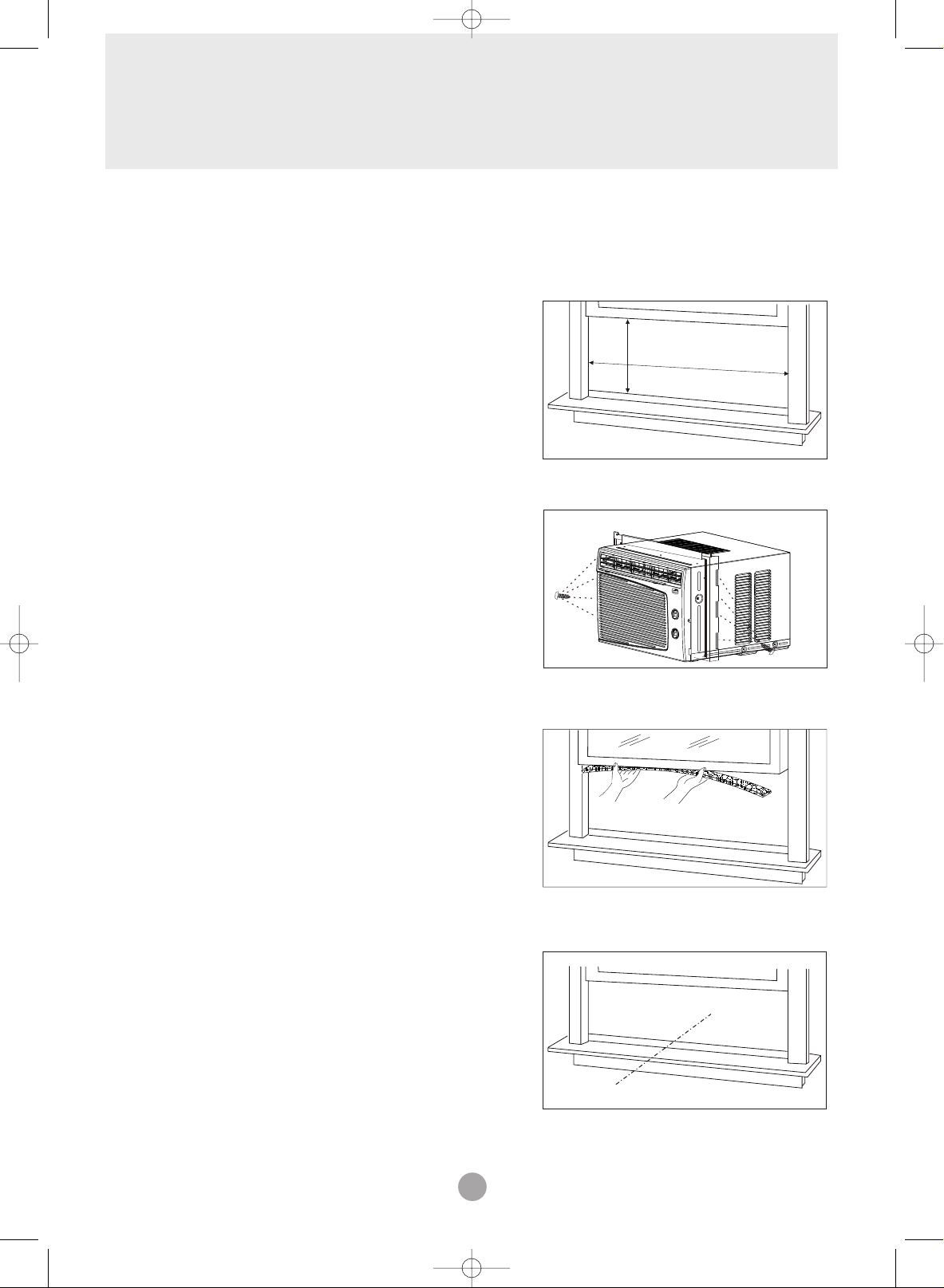
Window installation step
1. If your air conditioner cabinet 18'' wide, it will fit
window openings 21'' to 32'' in wide. Minimum
opening height is 14'' from bottom of sash to sill
(Fig. 1).
Min
''
14
21'' to 32''
2. Insert the guide panels into the guides of the air
conditioner. Fasten the curtains to the unit with screws
(Fig. 2).
3. Cut the adhesive-backed seal strip the window width.
Remove the backing from the seal strip and attach
the seal strip to the underside of the bottom window.
(Fig. 3)
Fig. 1
Fig. 2
Fig. 3
Seal
2/5 ''
Screws
4. Measure the inside window sill width and find
the center line as shown in Fig. 4.
Center Line
Fig. 4
 Loading...