

Page 1
INSTRUCTIONS
FOR USE
A-dec SC
AIR COMPRESSOR
Page 2

A-dec SC Air Compressor Instructions for Use
Copyright
© 2021 A-dec, Inc. All rights reserved.
A-dec, Inc. makes no warranty of any kind with regard to this material,
including, but not limited to, the implied warranties of merchantability
and tness for a particular purpose. A-dec, Inc. shall not be held liable
for any errors contained herein or any consequential or other damages
concerning the furnishing, performance or use of this material. The
information in this document is subject to change without notice. If you
nd any problems in the documentation, please report them to us in
writing. A-dec, Inc. does not warrant that this document is error-free.
No part of this document may be copied, reproduced, altered, or
transmitted in any form or by any means, electronic or mechanical,
including photocopying, recording, or by any information storage and
retrieval system, without prior written permission from A-dec, Inc.
Trademarks and Additional Intellectual Property Rights
A-dec, the A-dec logo, A-dec Inspire, Cascade, Century Plus, Continental,
Decade, ICX, ICV, Performer, Preference, Preference Collection,
Preference ICC, Radius, and reliablecreativesolutions are trademarks of
A-dec, Inc. and are registered in the United States and other countries.
A-dec 500, A-dec 400, A-dec 300, A-dec 200, and EasyFlex are also
trademarks of A-dec, Inc. None of the trademarks or trade names in this
document may be reproduced, copied, or manipulated in any manner
without the express, written approval of the trademark owner.
Certain touchpad symbols and icons are proprietary to A-dec, Inc. Any
use of these symbols or icons, in whole or in part, without the express
written consent of A-dec, Inc., is strictly prohibited.
Regulatory Information and Warranty
For additional required regulatory information and the A-dec warranty,
see the Regulatory Information, Specications, and Warranty document
p/n
86.0221.00) available in the Resource Center at www.a-dec.com.
(
Intended Use
A dental air compressor is intended to provide air pressure to dental
devices for use during diagnostic and therapeutic treatment by licensed
health care professionals.
Expected Service Life
The Expected Service Life of A-dec compressors is 10 years when
following the recommended maintenance schedule.*
Product Service
Product service is available through your local authorized A-dec dealer.
To locate an authorized dealer, or for additional service information,
visit www.a-dec.com or contact A-dec at 1.800.547.1883 in the USA and
Canada or 1.503.538.7478 worldwide.
Product Models and Versions Covered in This Document
Model Version Description
SC3/SC5
SC7/SC10
SC12
n/a Air Compressor
86.0887.00 Rev A
* Service Life information is provided for general planning purposes only and should not be
relied upon for any reason. Service Life does not include normal service “wear and tear”
components and is separate from the warranty period. There are no implied or explicit
extensions of the warranty period. For complete warranty details, see the Regulatory
Information, Specications, and Warranty document referenced above.
Page 3
A-dec SC Air Compressor Instructions for Use Content Map
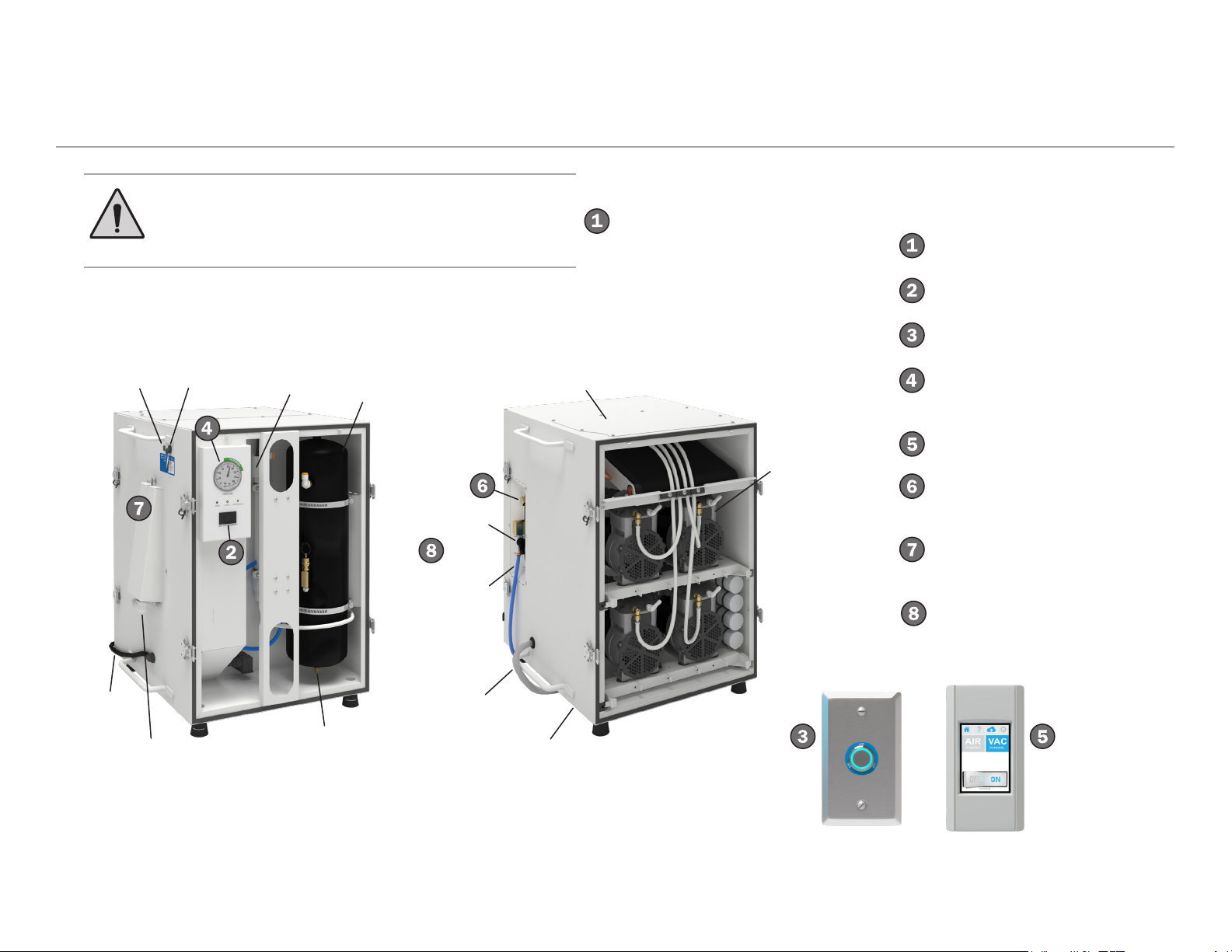
Content Map
Ethernet
Connection
WARNING Do not open or remove the compressor
service panels. These are intended for qualified
service technician access only and are removed from
the systems below for informational purposes only.
Remote
Switch
Connection
Air
Dryer
Air
Tank
Top Plate
Air Shutoff
Valve
Air
Discharge
Hose
Compressor
Pump with
Motor
Features/Topics
Safety Precautions ........................ 2
Master Power Switch ....................4
LED Push-Button Controls ............ 4
Control Panel/Pressure Gauge/
Status Indicators ............................ 5
Smart Shield Touchscreen ........4, 6
Maintenance/
Moisture Indicator .......................... 9
Fresh Air Housing/
Filter Replacement ......................10
Troubleshooting Tasks ................ 11
Power
Cord
Fresh Air
Intake
Connection
86.0887.00 Rev A 1
Tank Drain
Bleed Valve
Condensate
Hose
Condensate Tray
(not shown)
Page 4
A-dec SC Air Compressor Instructions for Use Safety Precautions and Other Regulatory Information
80 kPa
110 kPa
110 kPa
Safety Precautions and Other Regulatory Information
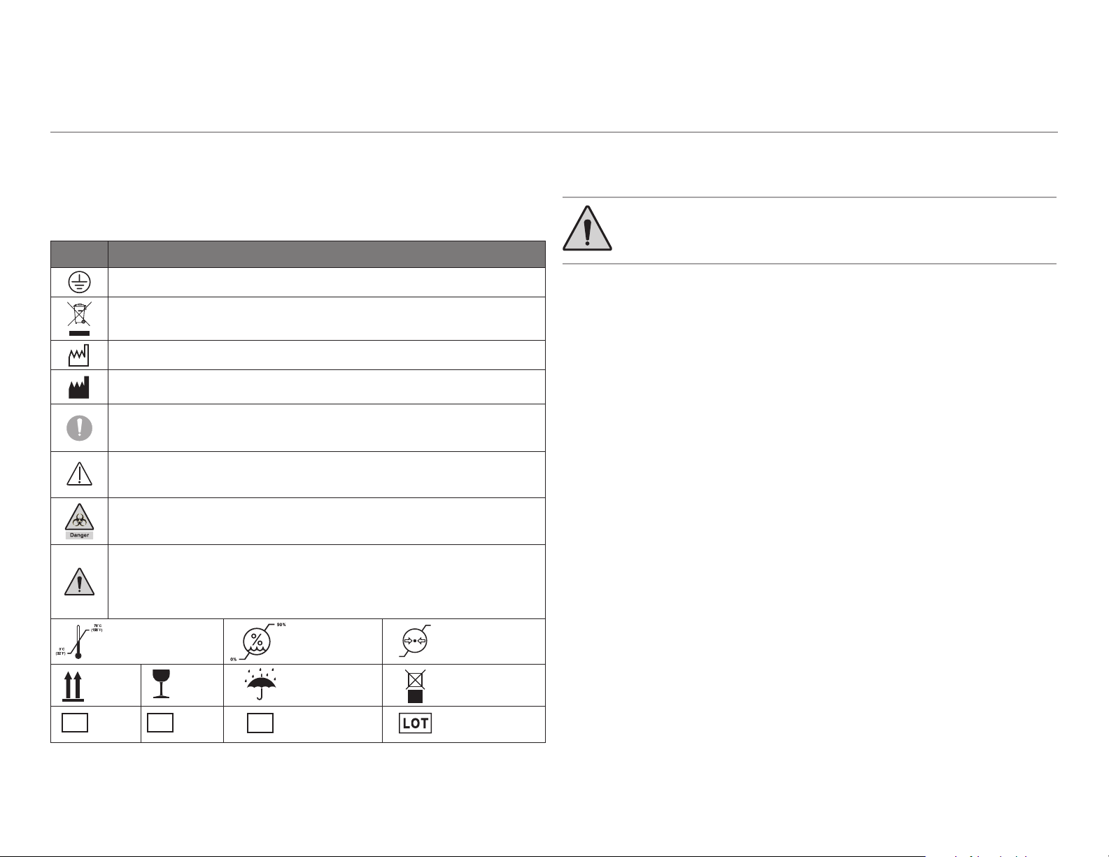
Identification of Symbols
These symbols appear on the actual product or are used in documentation to alert
the user about cautions, warnings, hazards, or tips.
Symbol Description
Protective earth (ground).
Electrical and electronic waste. Do not dispose of with domestic waste.
Date of manufacture.
Manufacturer of equipment.
General mandatory action sign. Not a caution. Take note of additional important
instructions.
e.g., NOTE: Assemble parts as shown.
Caution. Failure to follow instructions may result in product damage or minor injury.
e.g., CAUTION: Do not overtighten the adjustment screw. Overtightening could break
the screw.
Warning. Biological hazard.
e.g., WARNING: Infectious waste may be present. Follow asepsis protocol to prevent
cross contamination.
Warning. Failure to follow instructions may result in product damage or serious injury or
death.
e.g., WARNING: Turn off the power before removing the pump cover. Failure to turn off the
power before you begin this procedure can lead to product damage and result in serious
injury or death.
REF
Temperature shipping
and storage limits.
This way
up.
Model
Number
SN
Relative humidity
PN
shipping and
storage limits.
Part Number. Lot Code.
Fragile. Keep dry.
Serial
number.
80 kPa
Atmospheric
pressure shipping
and storage limits.
Do not stack.
Safety Precautions
WARNING Failure to follow these safety and operation
precautions can result in injuries or equipment damage.
The following safety precautions listed below must be observed:
1. Read all instructions completely before operating the air compressor.
2. For installation, follow all local electrical and safety codes, as well as the
National Electrical Code (NEC) and the Occupational Safety and Health Act
(OSHA).
3. Protect the power cable from coming into contact with sharp objects. Do not
kink the power cable and never allow it to come in contact with oil, grease, hot
surfaces, or chemicals.
4. Make certain that the power source conforms to the requirements of your
equipment.
5. Pull the main electrical disconnect switch and disconnect any separate control
lines, if used, before attempting to work or perform maintenance on the air
compressor or unit. “Tag Out” or “Lock Out” all power sources.
6. Do not attempt to remove any compressor parts without rst relieving the
entire system of pressure.
7. Do not attempt to service any part while the compressor is in an operational
mode.
8. Do not operate the compressor at pressures in excess of its rating.
9. Periodically check all safety devices for proper operation. Do not change the
pressure setting or restrict operation.
10. Be sure that no tools, rags, or loose parts are left on the compressor or
drive parts.
11. Do not use ammable solvents for cleaning any parts.
86.0887.00 Rev A 2
Page 5
A-dec SC Air Compressor Instructions for Use Safety Precautions and Other Regulatory Information
Safety Precautions (continued)
12. Exercise cleanliness during maintenance and when making repairs. Use a clean
piece of paper or cloth to cover and keep dirt away from parts and openings.
13. Do not operate the compressor without the service panels in place.
14. Do not operate the compressor in an environment that exceeds 104°F (40°C).
15. Do not operate compressor in areas where it might intake ammable or toxic
fumes.
16. Inspect the unit daily to observe and correct any unsafe operating condition.
17. Compressed air is a hazard and can result in air embolisms if it enters the
blood stream. Take care when using compressed air and only use air powered
medical products consistent with their intended use and user instructions.
18. Compressed air from this machine must not, under any circumstances, be used
for food processing or breathing air without adequate downstream lters,
puriers, and controls.
19. Always use an air pressure regulating device at the point of use. Do not use air
pressure greater than the marked maximum pressure of attachment.
20. Check hoses for weak or worn condition before each use, and make certain that
all connections are secure.
Decommissioning and Disposal of A-dec Equipment
A-dec dental equipment removed from service should be decommissioned in
accordance with local regulatory requirements. Circuit boards and electrical
cabling should be recycled as electrical salvage. Aluminum, brass, iron, and steel
components should be recycled as metal salvage. Molded plastic components
include mold marks indicating the type of plastic and should be recycled
accordingly. Any material unsuitable for recycling should be disposed of
appropriately. For information regarding material type of A-dec equipment, please
contact A-dec Customer Service.
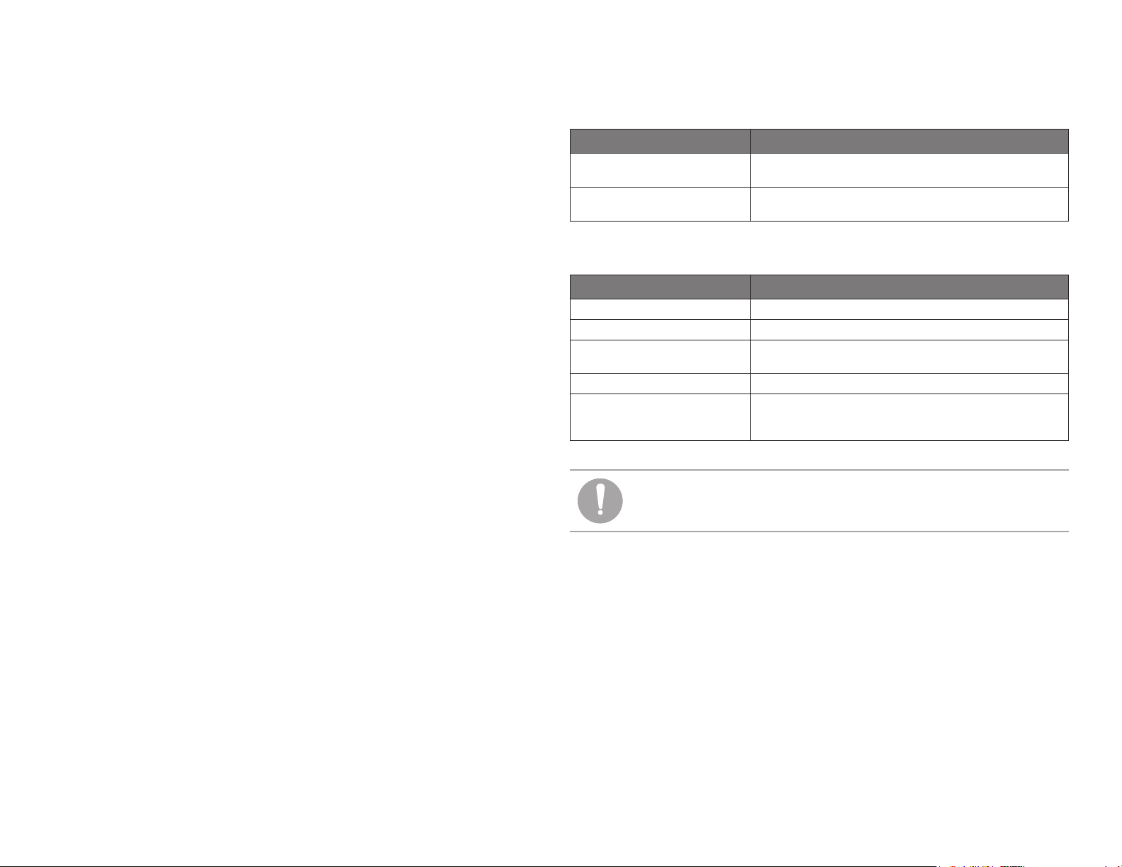
Environmental Specifications
Temperature/Humidity Specication
Storage/Transportation
Temperature
Operating Temperature
(Room Ambient Temperature)
32°F to 158°F (0°C to 70°C); relative humidity to 90%, no
condensation.
40°F to 104°F (4°C to 40°C); relative humidity to 80%, no
condensation.
Classification of Equipment (IEC-60601-1)
Type/Mode Classication
Types of Shock Protection CLASS I EQUIPMENT: All A-dec products with mains voltage.
Degree of Shock Protection Not Classied—no applied parts.
Degree of Protection Against
Water Ingress
Mode of Operation Continuous with 50% full load duty cycle.
Flammable Gasses Not suitable for use in the presence of a ammable anesthetic
Not Classied—IPX0.
mixture with air, oxygen, or nitrous oxide, where such gasses may
accumulate in concentration (closed space).
NOTE Allowable mains voltage fluctuations ± 10% of rated
voltage.
Electromagnetic Interference
A-dec mechanical room systems are designed and built to minimize electromagnetic
interference with other devices. However, if interference is noticed between another
device and your vacuum system:
• Remove interfering device from room.
• Plug interfering device into an isolated circuit.
• Increase separation between unit and interfering device.
• Contact your authorized A-dec dealer if interference persists.
86.0887.00 Rev A 3
Page 6

A-dec SC Air Compressor Instructions for Use Operate
Operate
Turn On/Turn Off Power
NOTE For longer periods of non-use, such as an extended
shutdown of the ofce, disconnect power to the compressor
to save energy and reduce the chance of air leaks in your
piping system and treatment rooms.
Master Power Switch
Master Power Switch
The master power switch turns the vacuum unit on or off. It also
overrides the other remote power functions. If your compressor is
connected to remote LED push-button controls or a Smart Shield
touchscreen, this switch should be in the REMOTE position.
LED Push-Button Control
(single-button)
LED Push-Button Control
(four-button)
Optional LED Push-Button Controls
If you have LED push-button controls, press the button once to turn the
compressor on or off. Blue LED lighting indicates that the compressor
is on. If the LED does not illuminate, check and verify that the master
power switch on the compressor is in the REMOTE position.
Optional Smart Shield Touchscreen Controls
For congurations with the Smart Shield
touchscreen, use the power switch icon
at the bottom of the screen or tap the AIR
icon to turn the compressor on or off. If the
Smart Shield does not operate, check and
verify that the master power switch on the
compressor is in the REMOTE position.
For more information on the touchscreen,
see “Smart Shield Touchscreen Controls”
on page 6.
86.0887.00 Rev A 4
OFFOFF
Page 7

A-dec SC Air Compressor Instructions for Use Operate
Control Panel Gauge and Operational Status
Pressure Gauge
After initial startup, when the system is fully pressurized, the pressure
gauge indicator should stay within the normal range. Contact your
authorized A-dec dealer if the pressure remains outside this range
during normal operation.
Status Indicators
Status
Indicators
The control panel includes three status indicators. These illuminate
differently, according to various conditions:
Indicator/
Color
RUN/
Green
INFO/Yellow
ATTENTION/
Yellow
Illumination
State Condition
Solid illumination. A motor is running.
Flashes continuously. The system is in standby (full pressure
reached, no motors running).
Flashes once every
10 seconds.
Flashes in intervals. The number of ashes per interval
Flashes in intervals. Fault code. For more information, see
The unit is connected to power.
indicates the number of motors
running.
“Troubleshooting Tasks” on page 12.
NOTE In addition to hearing the motors and pumps operate,
you may also hear other noises from the compressor. These
are normal and come from the cooling fans, air dryer, and
other components during various operational cycles.
86.0887.00 Rev A 5
Page 8

A-dec SC Air Compressor Instructions for Use Operate
Smart Shield Touchscreen Controls
The optional Smart Shield touchscreen provides power control and
system status of your mechanical room equipment.
Service
Contact
Information
Home
System
Status
Icons
(Tap to turn
equipment
on or off
individually.)
Remote Monitoring
Status
Software Version
and Reset
Power Switch
(Tap to turn all
attached equipment
on or off at the
same time.)
Tap the power switch icon at the bottom of the screen to turn all
connected equipment on or off at the same time. Tap the blue system
status icons to turn individual equipment on or off. These status icons
also dynamically change according to the operational state of the
equipment (see “Compressor System Status Icons” table on page 7).
Compressor Startup
When you rst start the compressor, Smart Shield displays the AIR
RUNNING icon, which includes the number of motors currently
running to increase air pressure (in the upper right corner of the icon).
When the system has reached the normal operating pressure range, the
AIR STANDBY icon appears.
AIR Running
(Pressurizing)
4
AIR Standby
(Pressurized)
NOTE If the Smart Shield does not operate, check and
verify that the master power switch on the compressor
is in the REMOTE position. For more information, see
“Troubleshooting Tasks” on page 11.
86.0887.00 Rev A 6
Page 9

A-dec SC Air Compressor Instructions for Use Operate
MANUAL
Smart Shield Touchscreen Controls (continued)
Compressor System Status Icons
Service
Contact
Information
Home
System
Status
Icons
(Tap to turn
equipment
on or off
individually.)
Remote Monitoring
Status
Software Version
and Reset
Power Switch
(Tap to turn all
attached equipment
on or off at the
same time.)
Icon State/Status
Displays during initial startup while the compressor motors
are pressurizing. The number in the upper right corner
indicates how many motors are currently running, which
varies per model (SC3: 2, SC5: 3, SC7: 4, SC10: 5, SC12: 6).
Displays intermittently while the compressor motors are
pressurizing the system, typically during initial system
startup.
Displays when the compressor motors have nished
pressurizing the system.
“MANUAL” appears on status icons when the master power
switch on the compressor is in the ON or OFF position. To
control power through the Smart Shield touchscreen, ensure
that the master power switch on the compressor is in the
REMOTE position.
Displays when the compressor is turned off from the Smart
Shield touchscreen controls.
OFF
Displays when the annual maintenance interval is reached.
This caution/reminder is reset whenever power to the
NOTE If additional warning icons appear on
system is disconnected.
your screen and are not shown here, contact your
authorized A-dec dealer for more information.
86.0887.00 Rev A 7
Displays when there is a fault in the system. Contact your
authorized A-dec dealer for service.
Page 10

A-dec SC Air Compressor Instructions for Use Operate
Smart Shield Touchscreen Controls (continued)
Additional Smart Shield Functions
Service
Contact
Information
Home
System
Status
Icons
(Tap to turn
equipment
on or off
individually.)
Remote Monitoring
Status
Software Version
and Reset
Power Switch
(Tap to turn all
attached equipment
on or off at the
same time.)
Icon State/Status
Q uestions?
1-800-547-1883
PRESS HERE TO
REQUEST SERVICE
Software V ersion
20180309
Displays contact information that will
route you to A-dec, Inc.
Displays your status as enabled if you
are registered with the remote
monitoring service. For questions,
contact your authorized A-dec dealer,
or call A-dec Customer Service.
Displays software version. The reset
button turns off the screen, reboots the
software, and reloads the equipment
status. You can use RESET during
specic faults with the equipment. For
more information, see “Troubleshooting
Tasks” on page 11.
RESET
86.0887.00 Rev A 8
Page 11

A-dec SC Air Compressor Instructions for Use Maintain/Troubleshoot
Maintain/Troubleshoot
Regular Maintenance Tasks
WARNING Do not attempt to open or remove the
compressor service panels. These are intended for
qualified service technician access only.
Control Panel
Status Indicators
Moisture
Service Panel
Indicator
(blue = normal
operation)
WARNING Before performing any maintenance function,
disconnect main power to the compressor and ensure that all
air pressure is relieved. Failure to do so may result in injury
or equipment damage.
To keep your compressor running smoothly, be sure to schedule a
service checkup with your authorized A-dec dealer every year. And
although the SC compressor requires very little maintenance, see the
table below for important recommended maintenance tasks.
Frequency Item Task/Procedure
Weekly Control panel and
moisture indicator.
Visually inspect the control panel.
If the air pressure does not remain
in the normal operation zone after
initial startup, contact your authorized
A-dec dealer for service. Ensure that
the RUN and INFO status indicators
are illuminating properly (see “Status
Indicators” on page 5 for more
information).
Visually inspect the moisture indicator.
Blue indicates normal operation. If
the indicator is pink, there’s moisture
in your compressed air. Contact your
authorized A-dec dealer for service.
Monthly Exterior case and
tubing connections.
86.0887.00 Rev A 9
Use a dry, lint-free cloth to dust off
and clean the exterior. Listen for any
noticeable air leaks.
Page 12

A-dec SC Air Compressor Instructions for Use Maintain/Troubleshoot
Regular Maintenance Tasks (continued)
WARNING Before performing any maintenance function,
disconnect main power to the compressor and ensure that all
air pressure is relieved. Failure to do so may result in injury
or equipment damage.
Contact your authorized A-dec dealer if you are unable to
access the air filters. Do not attempt to open or remove the
compressor service panels. These are intended for qualified
service technician access only.
Filter Housing
Thumbscrew
1
Fresh Air
Filter Housing
2
Foam Filter
Mesh Filter
Front Service Panel
Ambient Air
Screen Filter
3
Frequency Item Task/Procedure
Yearly Air lters:
• Fresh air foam
• Fresh air mesh
• Ambient air screen
Every
5 years
Internal dryer
cartridge lter.
Replace the fresh air and ambient air
lters once a year. Turn off power to the
compressor before following these steps:
1. Loosen and remove the fresh air
lter housing
remove the housing to access the
fresh air lters.
2. Pull out and replace the foam and
mesh lters. Reinstall the housing.
3. Slide the ambient air lter out from
the front service panel and replace.
*Forairlterreplacement,orderthefollowing
maintenance kits:
• p/n A0050, for model SC3/SC5/SC7
• p/n A0150, for model SC10/SC12
This task requires a service technician.
Contact your local authorized A-dec
dealer for the internal cartridge lter
replacement.
thumbscrew, then
86.0887.00 Rev A 10
Page 13

A-dec SC Air Compressor Instructions for Use Maintain/Troubleshoot
Troubleshooting Tasks
WARNING Do not attempt to open or remove the
compressor service panels. These are intended for
qualified service technician access only.
your compressor that may or may not require attention. For problems
that require access to internal compressor components, always contact
your local authorized A-dec dealer for service.
Condition Potential Cause Procedure/Remedy
The following table is intended to help you identify common issues with
LED push-button or
Smart Shield controls
do not function.
Air pressure outside
the normal range.
Master power switch on the compressor is not in
the REMOTE position.
Communication disruption/fault between system
and Smart Shield touchscreen.
Incomplete initial startup and pressurization. Check the INFO status indicator on the compressor control panel. If the indicator
A leak in the compressor, piping, or dental
equipment.
Ensure that the master power switch on the compressor is in the REMOTE
position. If it is, and you have push-button controls, contact your authorized
A-dec dealer for service. If the master power switch is in the REMOTE position
and you have the Smart Shield touchscreen, see the remedy below.
Tap on
resolve the condition, unplug the Smart Hub router power cord, wait 10 seconds,
then plug it back in. If this does not resolve the condition, contact your
authorized A-dec dealer for service.
is ashing in intervals, the compressor motors are still working to reach full
pressurization. Recheck after the compressor has completed the initial startup
sequence. If the pressure remains outside the normal range, contact your
authorized A-dec dealer for service.
Turn the air shutoff valve to the OFF (or “closed”) position to help identify if the
air leak is within the compressor or external to the compressor.
at the top of the touchscreen, then tap RESET. If this does not
OFF or
“Closed”
ON or
“Open”
With the valve closed (which shuts off
the air supply to the treatment rooms),
watch the pressure gauge to see if the
compressor has an internal leak. If
you detect any leaks, contact your
authorized A-dec dealer for service.
Be sure to return the air shutoff valve to
the ON (or “open”) position for normal
operation.
86.0887.00 Rev A 11
Page 14
A-dec SC Air Compressor Instructions for Use Maintain/Troubleshoot
Troubleshooting Tasks (continued)
WARNING Do not attempt to open or remove the
compressor service panels. These are intended for
qualified service technician access only.
Condition Potential Cause Procedure/Remedy
ATTENTION status
indicator is ashing.
1 time per interval
Excessive demand on the compressor (greater
than 100 percent capacity).
Contact your authorized A-dec dealer for service.
2-3 times per interval
4 times per interval
5 times per interval
High ambient temperature warning/shutdown. Contact your authorized A-dec dealer for service.
Annual maintenance timeout. Schedule an annual service checkup with your authorized A-dec dealer.
5-year maintenance timeout. Schedule service with your authorized A-dec dealer to remove and replace the
internal dryer cartridge lter.
6-12 times per interval
Moisture indicator
Mechanical fault with motor or fan. Contact your authorized A-dec dealer for service.
Dryer not cycling properly. Contact your authorized A-dec dealer for service.
is pink.
Dryer cartridge past working life (5 years). Contact your authorized A-dec dealer to remove and replace the internal dryer
cartridge lter.
Excessive Vibration. Worn vibration/tray isolators. Contact your authorized A-dec dealer for service.
86.0887.00 Rev A 12
Page 15

Page 16

A-dec Headquarters
2601 Crestview Drive
Newberg, Oregon 97132
United States
Tel: 1.800.547.1883 within USA/CAN
Tel: +1.503.538.7478 outside USA/CAN
www.a-dec.com
A-dec St. Louis
1601 Manufacturers Drive
Fenton, Missouri 63026
United States
A-dec Australia
Unit 8
5-9 Ricketty Street
Mascot, NSW 2020
Australia
Tel: 1.800.225.010 within AUS
Tel: +61.(0).2.8332.4000 outside AUS
A-dec China
A-dec (Hangzhou) Dental Equipment Co., Ltd.
Building 5, No. 528 Shunfeng Road
Tangqi Town, Yuhang District,
Hangzhou, Zhejiang, China 311100
Tel: 400.600.5434 within China
Tel: +86.571.89026088 outside China
A-dec United Kingdom
Austin House
11 Liberty Way
Nuneaton, Warwickshire CV11 6RZ
England
Tel: 0800.ADEC.UK (2332.85) within UK
Tel: +44.(0).24.7635.0901 outside UK
ÍvÈ.Ç(wÈ.00CÎ
86.0887.00 Rev A
Date of Issue 2021-01-19
Copyright 2021 A-dec, Inc.
All rights reserved.
IFUnewcov1
 Loading...