

Page 1
O
O
W
W
A
A
NEE
N
R
R
R’’SS
R
O--
O
2
2
& II
&
M
M
G//
G
NSSTT
A
N
A
N
N
U
P
P
U
R
O--
R
O
ALLLL
A
ALL
A
2
G
2
G
ATTII
A
O
O
N
N
Page 2

This manual must be kept in a safe place for future reference.
Be sure to read, understand and follow the instructions and
warnings contained in this manual.
¾ WARNING: Improper installation, adjustment, alteration,
service or maintenance can cause property damage, injury or
death. Read the installation, operating and maintenance
instructions thoroughly before installing or servicing this
equipment.
¾ FOR YOUR SAFETY: Do not store or use gasoline or other
flammable vapors and liquids in the vicinity of this or any other
appliance.
WARNINGS
¾ WHAT TO DO IF YOU SMELL GAS:
1. Do not try to light the appliance
2. Do not touch any electrical switches or use any phones
within the building
3. Immediately call your gas supplier from a neighbor’s phone
and follow the gas suppliers instructions
4. If you cannot reach your gas supplier, call the Fire
Department
NOTE: Obtain information to be prominently posted near the
oven from you gas supplier.
¾ In the event of a power failure, do not attempt to operate this
equipment.
ARO-2G Double Rack Oven - 2 - Rev. 1.0, Dec. 2006
Page 3

Page
1. Table of Contents………………………………………………….. 3
2. General Information…………………………………..………….... 4
3. Basic Operation………………………………………..……………7
4. Control Overview………………………………………..…………10
5. Entering Programmed Bake Cycles……………………………..14
6. Maintenance & Cleaning………………………………………….16
7. Assembly & Installation……………………………………………17
8. Electrical schematics………………………………………………50
CONTENTS
ARO-2G Double Rack Oven - 3 - Rev. 1.0, Dec. 2006
Page 4
GENERAL INFORMATION
Shipping support angle
ARO-2G Double Rack Oven - 6 - Rev. 1.0, Dec. 2006
Page 5

PREHEAT OVEN
1. Close oven door.
2. Press the “BAKE” key. The Bake indicator light and all the displays will
illuminate.
3. Enter a SET TEMPERATURE to preheat the oven by pressing the “UP”
or “DOWN” set temperature arrow keys to adjust the set temperature
displayed.
¾ NOTE: Racks will not start rotating until “TIMER START” key is
4. Allow oven to preheat at least 20 minutes longer from when the OVEN
TEMPERATURE reaches the SET TEMPERATURE.
MANUALLY SET CONTROL
1. Enter a SET TEMPERATURE, if different from preheat temperature, by
pressing the “UP” or “DOWN” set temperature arrow keys to adjust the
set temperature displayed.
pressed.
OPERATION
2. Enter a BAKE TIME (in minutes) by pressing the “UP” or “DOWN” bake
time arrow keys to adjust the bake time (in minutes) displayed.
3. Enter a STEAM TIME (in seconds) by pressing the “UP” or “DOWN”
steam time arrow keys to adjust the steam time (in seconds) displayed.
USING A PROGRAM TO SET CONTROL
1. Enter a PROGRAM # by pressing the “NEXT PROG.” key to change the
program number displayed.
¾ NOTE: The set temperature, bake time and steam time displayed will
be for Step 1 of the entered program # and the oven will preheat to the
set temperature display.
LOADING PROCEDURES
1. Slowly open the oven door.
¾ CAUTION: Steam and hot air will escape from oven door when
opened. To avoid burns keep hands and face away from door
opening. Oven interior surfaces are very hot, use oven mitt while
touching.
2. Align the channels on the oven rack(s) with the rack carrier and push to
the rear stop.
3. Close the oven door.
ARO-2G Double Rack Oven - 7 - Rev. 1.0, Dec. 2006
Page 6

¾ NOTE: Racks will not start rotating until “TIMER START” key is
pressed.
4. Press the “TIMER START” key to initiate the bake cycle. The indicator
light in the corner of the bake time display will begin blinking and the clock
will start counting down.
¾ NOTE: Oven damper can be opened during bake cycle to evacuate
steam by pressing the “DAMPER” key.
¾ NOTE: If using a programmed bake cycle with multiple steps the timer
counts down the duration of each step separately the buzzer won’t
sound until the time elapses on the last programmed step.
5. A buzzer will sound and all the displays will flash when the bake timer
display counts down to 00:00.
¾ NOTE: Rack will continue rotating until the “TIMER STOP” key is
pressed.
UNLOADING PROCEDURES
1. Press the “TIMER STOP” key to silence the buzzer and stop the rack
rotation.
OPERATION
2. Slowly open the oven door, swing door completely open.
¾ CAUTION: Steam and hot air will escape from oven door when
opened. To avoid burns keep hands and face away from door
opening. Oven racks and interior surfaces are very hot, use oven mitt
while touching.
3. Using oven mitts, open rack locks on rack carrier.
4. Using oven mitts, remove rack(s) from rack carrier.
¾ NOTE: The door could be closed and the “JOG” key pressed to rotate
the rack carrier 180
o
and improve access for removing the second
rack.
5. Close oven door.
SHUT DOWN PROCEDURES
1. Press the “OFF” key. The displays go blank and the oven will turn off.
¾ NOTE: The exhaust hood fan will continue to run for 20 minutes after
the oven is turned off.
¾ NOTE: To cool oven off quicker, press the “FAN” key and open the
oven door. The fan indicator light will illuminate and the fan will run
continuously without a call for heat.
ARO-2G Double Rack Oven - 8 - Rev. 1.0, Dec. 2006
Page 7

¾ WARNING: For service or extended periods of shutdown,
turn the power off at both the 120 V control ci rcuit and 208
– 480 V main power circuit breakers.
ARO-2G Double Rack Oven - 9 - Rev. 1.0, Dec. 2006
Page 8

Adjustment of Air Distribution Panel on New ARO/PRO Oven
*The louver settings are in millimeters.
*A set of metric Allen wrenches will facilitate the job.
*The measurements must be taken at the top and the
bottom of each adjusable louver,
Not at the top and bottom ends of the slots.
BACK MIDDLE FRONT
078
078
068
068
268
367
457
4 4.5 6
4 4.5 6
4.5 4.5 6
5 4.5 6
5 4.5 7
Prepared: 05/15/07
Page 9
6
5
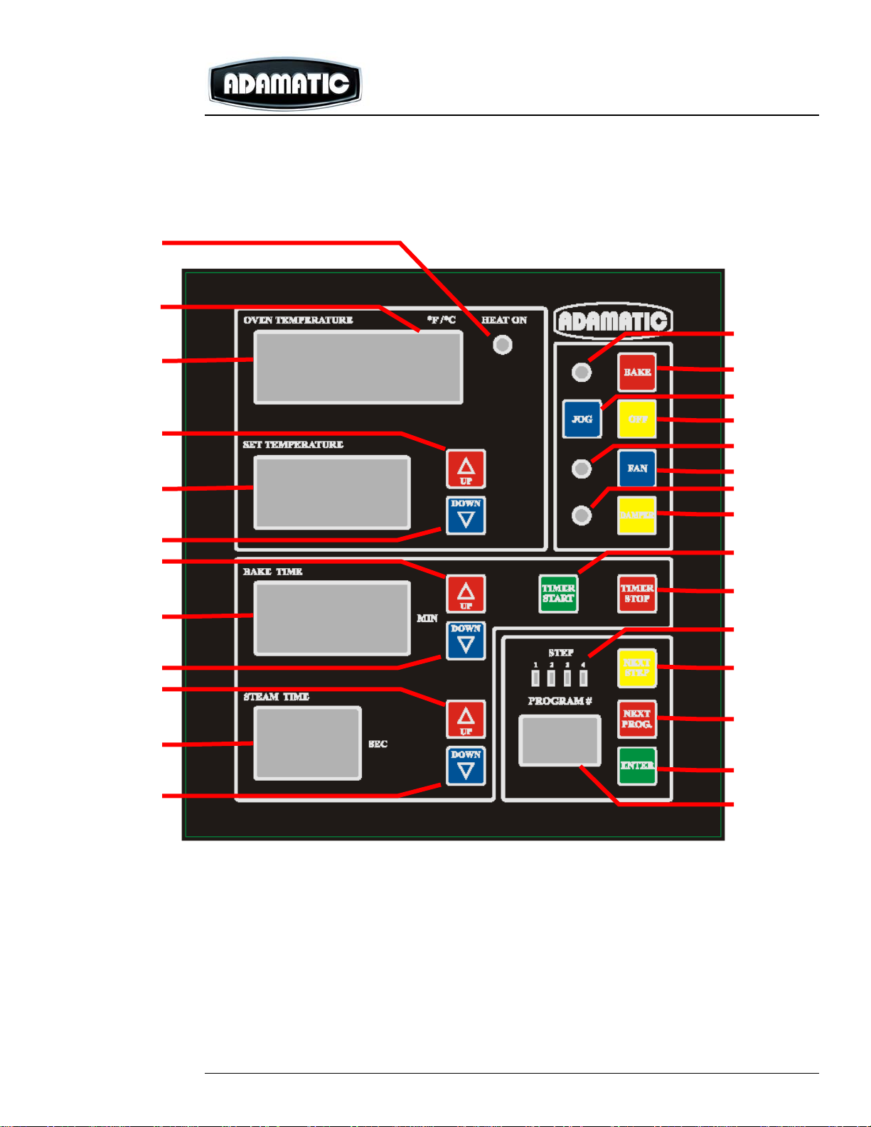
CONTROLS
16
1
3
2
4
8
7
9
11
10
15
19
22
21
13
14
24
23
25
27
12
26
ARO-2G Double Rack Oven - 10 - Rev. 1.0, Dec. 2006
Page 10

TEMPERATURE FUNCTIONS
1. “OVEN TEMPERATURE” DISPLAY – indicates the actual temperature
inside the oven
CONTROLS
¾ NOTE: The displayed temperature will be the same the set
temperature when the oven is within 10
o
F of the set temperature.
2. “SET TEMPERATURE” DISPLAY – indicates the temperature the oven is
set at
3. SET TEMPERATURE “UP” ARROW KEY – pressed to raise the
temperature the oven is set at
4. SET TEMPERATURE “DOWN” ARROW KEY – pressed to lower the
temperature the oven is set at
oF/o
5. OVEN TEMPERATURE “
C” DISPLAY – indicates the units
temperature is measured in (i.e. “F” for degrees Fahrenheit or “C” for
degrees Celsius)
6. “HEAT ON” INDICATOR LIGHT – illuminates when the control is
requesting heat
¾ NOTE: This light will go out when the oven has reached set
temperature.
TIMER FUNCTIONS
7. “BAKE TIME” DISPLAY – indicates the number of minutes the bake cycle
is set for or has remaining
¾ NOTE: An indicator light will blink in the lower right corner of the
display when the Bake Timer is actively counting down.
¾ NOTE: When less then 3 minutes is remaining in the bake cycle the
time will be displayed in min:sec instead of just minutes.
8. BAKE TIME “UP” ARROW KEY – pressed to raise the numb er of minutes
the bake timer is set for
¾ NOTE: Time can be added to the bake timer at any time during the
bake cycle.
9. BAKE TIME “DOWN” ARROW KEY – pressed to lower the number of
minutes the bake timer is set for
¾ NOTE: Time can be removed from the bake timer at any time during
the bake cycle.
10. “STEAM TIME” DISPLAY – indicates the time the steam cycle is set for or
has remaining
¾ NOTE: An indicator light will blink in the lower right corner of the
display when the Steam Timer is actively counting down.
ARO-2G Double Rack Oven - 11 - Rev. 1.0, Dec. 2006
Page 11

11. STEAM TIME “UP” ARROW KEY – pressed to raise the number of
seconds the steam timer is set for
12. STEAM TIME “DOWN” ARROW KEY – pressed to lower the number of
seconds the steam timer is set for
13. “TIMER START” KEY – pressed to start the bake timer counting down
¾ NOTE: The bake timer will stop counting down if the oven door is
opened.
14. “TIMER STOP” KEY – pressed to silence the bake timer buzzer at the
end of a bake cycle or to pause the bake timer in the middle of a bake
cycle
¾ NOTE: If bake timer has less then 1 minute left in the bake cycle,
pressing the “TIMER STOP” key will clear the remaining time and start
the bake timer buzzer, pressing it a second time will silence the bake
timer buzzer.
OVEN FUNCTIONS
15. “BAKE” KEY – pressed to turn on the oven and controls
CONTROLS
¾ NOTE: The control displays and bake indicator light will illuminate
when the oven is turned on.
16. BAKE INDICATOR LIGHT – illuminates when the oven is on
17. “OFF” KEY – pressed to turn off the oven and controls
¾ NOTE: The exhaust hood fan will continue to run for 20 minutes after
the oven is turned off.
o
18. “JOG” KEY – pressed to rotate the rack carrier 180
for easy removal
when two single racks are used
¾ NOTE: This key will only be active when the oven door is closed.
19. “FAN” KEY – pressed to switch to cool down mode
¾ NOTE: The fan indicator light will illuminate and the fan will run
continuously, without a call for heat, the oven door can also be opened
to help cool down the oven quicker.
20. FAN INDICATOR LIGHT – illuminates when the oven is in cool down
mode
21. “DAMPER” KEY – pressed to open the motorized cavity damper (if
provided).
¾ NOTE: The damper indicator light will illuminate when the damper is
open.
22. DAMPER INDICATOR LIGHT – illuminated whenever the damper is open
with either the “DAMPER” key, “FAN” key or during a programmed bake
cycle. .
ARO-2G Double Rack Oven - 12 - Rev. 1.0, Dec. 2006
Page 12

PROGRAMMING FUNCTIONS
23. “NEXT STEP” KEY – pressed to cycle through steps in a bake cycle
program
¾ NOTE: The step indicator lights will illuminate to show the active step.
24. “STEP” INDICATOR LIGHTS – Indicates the active step when
programming or running a bake cycle program.
25. “NEXT PROG.” KEY – pressed to cycle through available bake cycle
programs
26. “PROGRAM #” DISPLAY – Indicates the bake cycle program selected to
run or to be programmed.
27. “ENTER” KEY – pressed to select a program number or to save a bake
cycle program while in programming mode.
CONTROLS
ARO-2G Double Rack Oven - 13 - Rev. 1.0, Dec. 2006
Page 13

ENTER PROGRAMMING MODE
1. With the oven and control off, press and hold the “NEXT PROG”, “NEXT
STEP” and “BAKE” keys at the same time for 3 seconds.
2. When the control beeps once, release the buttons and all the displays will
illuminate but the PROGRAM # display will be flashing a number.
SELECT PROGRAM NUMBER
1. Press the “NEXT PROG” key until the program number to be entered is
indicated in the PROGRAM # display.
¾ NOTE: Each time the “NEXT PROG.” Key is pushed the program
number will increment one digit, if you press and hold the “NEXT
PROG.” key the program number will be scrolled through.
¾ NOTE: The Step 1 indicator will be illuminated in the STEP indicator
lights.
ENTER STEP 1 PARAMETERS
PROGRAMMING
1. Enter a Step 1 SET TEMPERATURE by pressing the “UP” or “DOWN”
set temperature arrow keys to adjust the set temperature displayed.
2. Enter a Step 1 BAKE TIME (in minutes) by pressing the “UP” or “DOWN”
bake time arrow keys to adjust the bake time (in minutes) displayed.
2. Enter a Step 1 STEAM TIME (in seconds) by pressing the “UP” or
“DOWN” steam time arrow keys to adjust the steam time (in seconds)
displayed.
3. Enter a Step 1 DAMPER TIME (in minutes) by pressing and holding the
damper button while pressing the “UP” or “DOWN” bake time arrow keys
to adjust the damper open time displayed in the bake time display.
¾ NOTE: The damper will be held open for the entered period of time at
the end of a step. (For example - if the damper is programmed for 1
minute in a step with a 5 minute bake time, the damper won’t open
until the first 4 minutes of the step have expired.)
¾ NOTE: The damper time can not exceed the total bake time for the
step.
ENTER NEXT STEPS
1. Press the “NEXT STEP” key to proceed to the next step as indicated by
the steps indicator lights.
2. Repeat Steps 1 – 4 under ENTER STEP 1 PARAMETERS.
3. Press the “NEXT STEP” key to proceed to the next step as indicated by
the steps indicator lights as required.
ARO-2G Double Rack Oven - 14 - Rev. 1.0, Dec. 2006
Page 14

¾ NOTE: The next step can not be accessed until a Bake Time greater
then 00:00 is entered for the current step.
SAVING PROGRAMS
1. Press the “ENTER” key to save the program currently being worked on a s
indicated by the steps indicator lights.
2. Press the “NEXT PROG” key until the program number to be entered is
indicated in the PROGRAM # display.
EXITING PROGRAMMING MODE
1. Press the “OFF” key to turn the oven off and exit programming mode.
¾ NOTE: Press the “ENTER” key prior to the “OFF” key to save any
changes made to the active program.
PROGRAMMING
ARO-2G Double Rack Oven - 15 - Rev. 1.0, Dec. 2006
Page 15

DAILY CLEANING
1. Allow oven to cool until it reaches room temperature.
¾ NOTE: To cool oven off quicker, press the “FAN” key and open the
oven door. The fan indicator light will illuminate and the fan will run
continuously without a call for heat.
2. Sweep out interior of the oven.
WEEKLY CLEANING
1. Perform Daily Cleaning.
2. Clean both sides of door window and interior surface of the light window
using a mild soap/water solution or commercial glass cleaner and a clean
soft towel.
¾ NOTE: Heavy build-up on the interior surface of the glass may be
cleaned using a straight blade window scraper.
3. Clean interior stainless steel surfaces of the oven using a mild soap/water
solution and wipe dry with clean soft towel.
CLEANING
¾ CAUTION: Never use chlorinated cleaners, abrasive pads or metallic
scrapers on stainless steel surfaces.
¾ Note: When cleaning stainless steel wipe the surfaces by following the
grain.
4. Clean exterior stainless steel surfaces of the oven using a mild
soap/water solution and wipe dry with clean soft towel. A stainless steel
polish may be used after initial cleaning
¾ CAUTION: Never use chlorinated cleaners, abrasive pads or metallic
scrapers on stainless steel surfaces.
¾ Note: When cleaning stainless steel or applying polish wipe the
surfaces by following the grain.
5. Clean the control panel using a mild soap/water solution and a clean soft
towel.
¾ CAUTION: Never use chlorinated cleaners, abrasive pads or metallic
scrapers on control panel.
ARO-2G Double Rack Oven - 16 - Rev. 1.0, Dec. 2006
Page 16

¾ WARNING: Installation must be performed by a factory
authorized installation company. Improper installation can
cause personnel injury and/or damage the equipment. Oven
warranty will be void if installation is not performed by a
factory authorized installation company.
¾ WARNING: Installation and utility connections must be
performed by a licensed contractor to all applicable local
codes, or in the absence of local codes, with th e Nati onal Fuel
Gas Code, ANSI Z223.1.
¾ WARNING: Oven must be electrically grounded in accord ance
with the local codes, or in the absence of local codes, with
the National Electrical Code, ANSI/NFPA 70-1996.
¾ CAUTION: Oven must be installed heat resistant floor to reduce risk of
fire.
ASSEMBLY
PREPARING SITE
1. Verify there is adequate egress to bring the oven sections to where they
are being installed
¾ Heat Exchanger Section: 26” W x 69-1/2 D x 99” H
¾ Front Section with Door: 63” W x 36-1/4” D x 88” H
¾ Rear Section: 63” W x 33-3/4” D x 90” H
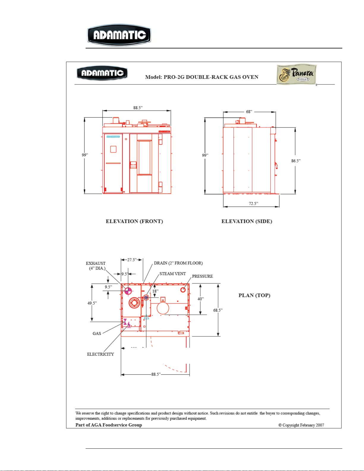
2. Verify there is sufficient space for the oven to be installed.
¾ Width: 88”
¾ Depth: 67-1/4” (plus 37” for door swing)
¾ Height: 106” minimum (120” recommended for service)
NOTE: It is recommended to have 2 feet clearance on all sides of the
oven to ease the assembly process.
3. Verify the floor under and 37” in front of oven is level to within ¼”.
4. Verify flooring is of a heat resistant construction both under and in front of
the oven where hot racks will be removed.
5. Verify the following utilities have been provided:
¾ Electrical: 120/60/1 @ 7.4 amp control circuit
208 – 240/60/3 @ 8.4 amp main power supply
(440 – 480/60/3 @ 4.2 amp optional power supply)
NOTE: National Electrical Code requires a disconnecting means
within sight of oven or be capable of being locked open.
ARO-2G Double Rack Oven - 17 - Rev. 1.0, Dec. 2006
Page 17

¾ Gas: 1” NPT @ 375,000 BTU’s Natural Gas with 7” – 14” WC static
pressure
(Optional LP requires 9” – 14” WC static pressure)
¾ Water: ½” NPT with 20 – 75 psi dynamic pressure
¾ Drain: 1” NPT
¾ Combustion Vent: 8” diameter
NOTE: Oven is supplied with barometric damper and 175 cfm draft
inducer.
¾ Hood Vent: 8” diameter
NOTE: 6” steam damper and 6” over pressure outlets to be ducted 8”
hood vent.
RECEIVING AND UNCRATING
1. On receipt of oven, check for both visual and concealed shipping
damage. Visible damage should be noted on the freight bill at time of
delivery and signed by the carrier. Claims for concealed damaged should
be made with the carrier’s agent within 15 days of delivery.
NOTE: If a claim is made, save all packing material for inspection by the
carrier.
2. Move oven crates to area the oven is to be installed. Remove the crating
material and plastic wrap from each section, but to not remove the straps
holding them to the skid.
3. Remove the following loose parts that are packaged with the rear section:
F
E
C
D
A Draft Inducer 1
B Barometric Damper 1
C Pressure Switch w/ Tube & Bracket 1
ARO-2G Double Rack Oven - 18 - Rev. 1.0, Dec. 2006
Page 18

K
D Carrier and Shaft Assembly 1
E Pivot Bracket Assembly 1
F Turnbuckle Assembly 1
G
G Cam Lift 1
H Steam Trays 99
I Steam Damper 1
J Hardware Kit 1
K Rack Limit Switch Bracket 1
ARO-2G Double Rack Oven - 19 - Rev. 1.0, Dec. 2006
Page 19

O
L Ramp 1
M Heat Exchanger Splash Shield 1
N
N Front Interior Side Panel 1
ARO-2G Double Rack Oven - 20 - Rev. 1.0, Dec. 2006
Page 20

O Rear Interior Side Panel 1
P Exterior Side Panels 2
ARO-2G Double Rack Oven - 21 - Rev. 1.0, Dec. 2006
Page 21

R
Q Front Steam Injection Pipe 1
R Rear Steam Injection Pipe 1
S Steam Drain Pan 1
T Steam Tray Mullion 1
ARO-2G Double Rack Oven - 22 - Rev. 1.0, Dec. 2006
Page 22

U Top Cover Panel (heat exchanger to
chamber section)
V Top Cover Panel (front chamber to rear
chamber)
W Rack Support Beam 1
1
1
X Interior Top Trim 1
4. Open the hardware box and check for the following contents:
ARO-2G Double Rack Oven - 23 - Rev. 1.0, Dec. 2006
Page 23

m
h
g
o
p
q
l
u
t
aa
a Steam Nozzle Cover
b Damper Clevis 1
c “U” Bolt with Nuts 1
d Steam Cable Bracket 1
e Cam Lift Shim Plates
f Teflon Tape 1 Roll
g Steam Injection Pipe Bracket 2
h Steam Injection Pipe Hold Down 2
i ? mounting Plate 1
j ½” Brass Union (Male to Female) 1
k ½” Brass Cap 1
l ½” Brass Nut 1
m 8 mm Wash er 1
n 10 mm Washer 1
o 10 mm x 80 mm Black Bolt (long) 1
p 8 mm x 20 mmBlack Bolt (short) 1
q 8 mm x 20 mm Stainless Steel Bolt 2
r 8 mm x 20 mm Stainless Steel Allen Bolt 1
s Pipe Gasket 1
t Lock Nut 1
u High Temp Silicone 1
v Insulation Hanger 1
w 8 mm x 25 mm Brass Bolt 1
x 5 mm x 16 mm Stainless Steel Screw 1
y 8 mm Brass Nut 1
z 8 mm Stainless Steel Nut
aa 8 mm Steel Nut
y
ARO-2G Double Rack Oven - 24 - Rev. 1.0, Dec. 2006
Page 24

5. If any of these parts are missing, please contact Adamatic to acquire a
replacement.
ASSEMBLE BAKE CHAMBER
1. Tilt the three bake chamber section to the vertical position.
¾ Raise each section using a forklift (if a forklift is not available use a
pallet jack, but do not try to lift these sections by hand). Place the
forks under the skid at the top of each section and tilt up 60
o
.
ARO-2G Double Rack Oven - 25 - Rev. 1.0, Dec. 2006
Page 25

¾ Raise each section to the vertical position by hand and carefully lower
them to the floor as to do not damage them.
¾ WARNING: Keep body parts from beneath the oven during the
raising process.
¾
¾ Assemble Front Bake Chamber Section to Rear bake Chamber
Section
1. Place the rear baking section first as close to the final position as possible
leaving 2 feet clearance between wall and oven section
2. .Place the front baking section in front of the rear baking section allowing
6 to 8 inches between the sections to apply a silicone bead
NOTE: Apply silicone only between the baking sections not the heating
section.
¾ .
ARO-2G Double Rack Oven - 26 - Rev. 1.0, Dec. 2006
Page 26

Silicone Bead
.
3. Apply a 3/8” bead of silicone on the mating flange making sure you go
around bolt holes. Apply a heavier bead in the corners. Silicone the floor
seam.
4. After the bead has been applied move the front section to join up with the
rear section making sure the section line up. Make sure the 4 alignment
pins for the line up
5. Use non-stainless steel bolts with s/s nuts and washes to fasten sections
together. Use a washer on both the bolt and nut side. Do not tighten
until all bolts are in place
6. Tighten all bolts.
> NOTE: Remove shipping bar from bake chamber.
Assemble Bake Chamber to Heat Exchanger section
1. Move the heating section into place leaving 8 to 12 inches between
baking section and heating section
3. Apply a 3/8” bead of silicone on the mating flange making sure to go
around bolt holes. Apply a heavier bead in the corners.
Silicone the floor seam.
4. Move heating section and bake chamber together and lining up bolt
holes. Make sure studs on heating section pass through holes in Bake
chamber first.
5. Install all bolts across the top, back and inside the baking chamber. Use
s/s bolts on inside and non-stainless on the outside and top
6. After all bolts are in place ,tighten all bolts
ARO-2G Double Rack Oven - 27 - Rev. 1.0, Dec. 2006
Page 27

INSTALL STEAM DRAIN PAN
1. Install steam drain pan.
¾ Screw one 1” diameter lock nut on rear drain pipe.
¾ Place one 1” diameter pipe gasket on rear drain pipe.
¾ Insert rear drain pipe into hole in rear of heat exchanger section.
¾ Apply a bead of silicone around flange on front drain manifold.
¾ Align hole in front of steam drain pan with front drain manifold and
secure with four 8mm x ????? stainless steel bolts, 8 mm stainless
steel washer and 8 mm stainless steel nuts.
ARO-2G Double Rack Oven - 28 - Rev. 1.0, Dec. 2006
Page 28

¾ Tighten the locknut on the rear drain pipe against the interior wall of
the heat exchanger section.
¾ Place the second 1” diameter pipe gasket on the rear drain pipe from
the exterior of the heat exchanger section.
¾ Screw the second 1” diameter lock nut on the rear drain pipe from the
exterior of the heat exchanger section and tighten
Installing Insulation and Exterior Wall Panels
> Insure all bolts and nuts are tight
> Fill all exterior oven section seam with sheets of mineral wool, 2
layers thick.
> Use insulation holders to keep insulation in place
> Install wall panels (P) on the side and back
> If oven is draining from the back remove knockout in bottom of cover.
NOTE : This would be a good time to move the oven to its final resting
place before you add more weight to the oven.
2. Install the heat exchanger splash shield over the opening in front of the
heat exchanger.
ARO-2G Double Rack Oven - 29 - Rev. 1.0, Dec. 2006
Page 29

¾ Bend the eight (8) tabs on the heat exchanger splash shield 90
¾ Place the splash shield over the opening by inserting the tabs into the
slots on the heat exchanger section.
3. Install the steam tray mullion using XXXXXX bolts .
¾
o
.
4. Install the single row steam trays toward the front of the oven.
¾ Apply Teflon tape and screw the brass nut and female end of the
unions to the front steam pipes in the roof in front of the heat
exchanger.
¾ Apply Teflon tape and screw the brass cap to the long end of the front
steam injection pipe.
ARO-2G Double Rack Oven - 30 - Rev. 1.0, Dec. 2006
Page 30

¾ Apply Teflon tape and screw the male half of the brass union to the
short end of the front steam injection pipe.
¾ Secure the rear and front steam injection tubes to the brass unions in
the ceiling with the injection branches oriented away from the heat
exchanger.
NOTE: Steam injection tubes are only being used to determine
position of steam nozzles covers and will be re-installed under steam
nozzle covers after steam trays have been installed.
¾ Bend the tabs on only one sides of eight (8) steam nozzle covers as
shown below.
ARO-2G Double Rack Oven - 31 - Rev. 1.0, Dec. 2006
Page 31

¾ Install the first steam tray in the two slots in the front mullion such that
the open end rests against the edge of the steam drain pan.
¾ Install the next steam tray in the two slots in the middle mullion such
that the open end rests against the first steam tray.
¾ Continue installing steam trays, alternating sides until your reach the
height of the first branch on the steam injection pipe.
ARO-2G Double Rack Oven - 32 - Rev. 1.0, Dec. 2006
Page 32

¾ Place a steam nozzle cover in the tray such that the bent tab is toward
the inside of the oven and the long end of the cover extends to the rear
of the oven.
¾ Continue installing steam trays and steam nozzle covers until all the
slots in the mullions have been filled.
¾ Unscrew the steam injection pipe from the union in the roof, rotate it
such that the branches extend under the steam nozzle covers and
attach it back to the union in the roof
ARO-2G Double Rack Oven - 33 - Rev. 1.0, Dec. 2006
Page 33

5. Install the single row steam trays toward the front of the oven.
¾ Apply Teflon tape and screw the brass nut and female end of the
unions to the rear steam pipe in the roof in front of the heat exchanger.
ARO-2G Double Rack Oven - 34 - Rev. 1.0, Dec. 2006
Page 34

¾ Apply Teflon tape and screw the brass cap to the short end of the rear
steam injection pipes.
¾ Apply Teflon tape and screw the male half of the brass union to the
long end of the rear steam injection pipe.
ARO-2G Double Rack Oven - 35 - Rev. 1.0, Dec. 2006
Page 35

¾
¾ Secure the rear and front steam injection tubes to the brass unions in
the ceiling with the injection branches oriented away from the heat
exchanger.
NOTE: Steam injection tubes are only being used to determine
position of steam nozzles covers and will be re-installed under steam
nozzle covers after steam trays have been installed.
¾ Bend the tabs on both sides of eight (8) steam nozzle covers for use in
the first row steam trays.
ARO-2G Double Rack Oven - 36 - Rev. 1.0, Dec. 2006
Page 36

¾ Bend the tabs on only one sides of eight (8) steam nozzle covers as
shown below.
ARO-2G Double Rack Oven - 37 - Rev. 1.0, Dec. 2006
Page 37

Install steam center support. Slip tab on top of support into receiver on
inside ceiling of oven, angle support so bottom of support is in drain
pan, bring support vertical. It should line up with support in heating
section
Mount inside roof cover strip using s/s 4 mm bolts
¾ Install the first steam tray in both rows in the two slots in the middle
mullion such that the open end rests in the steam drain pan toward the
rear of the oven.
¾ Install the next steam tray in the two slots in the middle mullion such
that the open end rests against the first steam tray.
¾ Continue installing steam trays, alternating sides until your reach the
height of the first branch on the steam injection pipe.
¾ Continue installing steam trays, alternating sides until your reach the
height of the first branch on the steam injection pipe.
¾ Place the steam nozzle cover with both tabs bent in the first steam tray
with the long end toward the front of the oven and the steam nozzle
ARO-2G Double Rack Oven - 38 - Rev. 1.0, Dec. 2006
Page 38

cover with one bent tab in the second row of steam trays also with the
long end toward the front of the oven.
¾ Continue installing steam trays and steam nozzle covers until all the
slots in the mullions have been filled.
¾ Unscrew the steam injection pipe from the union in the roof, rotate it
such that the branches extend under the steam nozzle covers and
attach it back to the union in the roof.
ARO-2G Double Rack Oven - 39 - Rev. 1.0, Dec. 2006
Page 39

6. Install water tube bottom clamp. ( G,H)
7. Mount front steam unit cover (O) using brass 8mm bolts with s/s washers.
8. Mount rear steam unit cover (N) using brass 8mm bolts with s/s washers
ARO-2G Double Rack Oven - 40 - Rev. 1.0, Dec. 2006
Page 40

NOTE: Where front and rear panels overlap use 8mm round head bolts
AIR DISTRIBUTION PANEL
Install the air distribution panels on the interior right side of baking chamber.
> Mount the rear panel which has 2 rows of slots using 8mm brass bolts
and s/s washers
> Mount the front panel which has 1 row of slot using 8mm brass bolts
with s/s washers
ARO-2G Double Rack Oven - 41 - Rev. 1.0, Dec. 2006
Page 41

> Leave all bolts loose. Where panels meet apply a bead of silicone (red)
and move panels together. Tighten all bolts and remove excess
silicone
RACK LIFT ASSEMBLY
> Bolt the rack lift support beam (W) in place. This beam mounts across
the width of the bake Chamber on top of oven. It fastens with 2 10mm
bolts on each end’
> NOTE: After the beam is mounted it is a good time to fill in the seams
on top of the oven with mineral wool insulation and to bolt on the top
covers which cover insulation using Non-stainless steel 8mm bolts and
washers.
ARO-2G Double Rack Oven - 42 - Rev. 1.0, Dec. 2006
Page 42

Adjustment of Air Distribution Panel on New ARO/PRO Oven
*The louver settings are in millimeters.
*A set of metric Allen wrenches will facilitate the job.
*The measurements must be taken at the top and the
bottom of each adjusable louver,
Not at the top and bottom ends of the slots.
BACK MIDDLE FRONT
078
078
068
068
268
367
457
4 4.5 6
4 4.5 6
4.5 4.5 6
5 4.5 6
5 4.5 7
Prepared: 05/15/07
Page 43

> Bolt the lifting cam (G) to the rack support beam. ( there are shims
provided for height adjustment for different style rack lifts. The ‘C’ style
rack lift requires no shims) Make sure the orientation is correct.
> Insert the rack lift (D) from inside the oven up through the roof
> Install the retaining ring to hold the shaft in place
> Install the turning cam (E) with the recessed cup up and the rod end
pointing towards the hinge of the baking chamber door.
> Install the thrust bearing with the large inside diameter on the bottom. The
bottom race should fit loosely over the shaft and the top race should fit
snug. It’s a good idea to lubricate this bearing at this time with high temp
grease
> Install the upper bearing cup with recess down to cover bearing
Install the 2 large washers
> Install the pulley making sure key is in keyway
> Install 1” washer and nut and tighten
> Tighten set screws in pulley
> Install turn buckle rod assembly (F) with the forked end of the turn buckle
attached to the rod end of the turning cam.
ARO-2G Double Rack Oven - 43 - Rev. 1.0, Dec. 2006
Page 44

> Secure the rod end of this assembly to the flat plate of the bake chamber
hinge assembly.
Install the rack drive belt
Install the rack stop switch bracket and switch
ARO-2G Double Rack Oven - 44 - Rev. 1.0, Dec. 2006
Page 45

WATER SOLENIOD
> Install the water solenoid assembly to the rear ½” pipe that extends
through the roof of the oven. Make sure the compression fitting faces the
front pipe
> Connect the coupling and 90 degree elbow to the from ½” pipe that
extends through the roof of the oven. Make sure the compression fitting
faces the rear pipe.
> Connect the 2 together with the copper tube provided
ARO-2G Double Rack Oven - 45 - Rev. 1.0, Dec. 2006
Page 46

DOOR SWITCH
> The door switch is mounted through the light fixture compartment on a
bracket located near the bottom of the compartment. Remove 1 mounting
nut and pass shaft of the switch through mounting hole and secure with
the nut you just removed on the other side.
> Adjust the switch so that the plunger moves freely with the door open or
closed.
LIGHTS
> The light fixture is installed between the brackets provided and is allowed
to pivot freely for placement of the tubes and removal of the tubes when
they go out. There is 1 bolt at the top of the fixture and 1 at the bottom.
DO NOT TIGHTEN THESE BOLTS
> The color coded wires connect to the ‘J’ box mounted in the burner
compartment Use the included wire nuts.
ARO-2G Double Rack Oven - 46 - Rev. 1.0, Dec. 2006
Page 47

MOUNT EVACUATION DAMPER ASSEMBLY
¾ Mount Damper assembly (I) using 4 brass bolts with s/s washers
¾ Fold and slide damper clevis (B) over damper shaft
¾ Use damper ‘U’ bolt (C) to secure to shaft
ARO-2G Double Rack Oven - 47 - Rev. 1.0, Dec. 2006
Page 48

ARO-2G Double Rack Oven - 48 - Rev. 1.0, Dec. 2006
Page 49

¾ Mount cable mount bracket (D) to roof panel
¾ Attach cable to bracket and to damper clevis
¾ Adjust cable so with damper knob pulled out damper is fully open
ARO-2G Double Rack Oven - 49 - Rev. 1.0, Dec. 2006
Page 50

ARO-2G Double Rack Oven - 50 - Rev. 1.0, Dec. 2006
ARO-2G Double Rack Oven - 50 - Rev. 1.0, Dec. 2006
Page 51

ARO-2G Double Rack Oven - 51 - Rev. 1.0, Dec. 2006
Page 52

ARO-2G Double Rack Oven - 52 - Rev. 1.0, Dec. 2006
ARO-2G Double Rack Oven - 52 - Rev. 1.0, Dec. 2006
 Loading...