


Installation, Operation and Troubleshooting Instructions
Adamatic Modular Proofers
For Panera Roll-In Model: AP-51
Manual Part No.: P6924700
Rev: 03
Print Date: xx/xx/xx
6 0 7 I n d u s t r i a l W a y, E a t o n t o w n , N J 0 7 7 2 4
Phone: (800) 5262807 Fax: (732) 544-0735 Website: www.adamatic.com
Proofer Cabinet Installation & Initial Start-Up Checklist
Proper installation is the first step to operation. We recommend that your proofer cabinet be installed by an authorized Certified Installer. This original checklist is to be signed and returned to Adamatic with warranty card.
Electrical
Record Voltage to Proofer Cabinet (*recommended 220-240V/60Hz/3Ph) Voltage Reading: __________________
*For proofer cabinets installed in older facilities, make sure a qualified electrician has confirmed that there are no Delta or Wild Legs as part of the main power supply. Fluctuating or spiking voltage can destroy electronic components that will not be covered by warranty.
Record Amperage
Amperage Reading: ________________
Components
Check Fans for Proper Rotation (*fans should be pushing or blowing in outward direction)
Test Light in Proof Box (*if required)
Check Door(s) Operation
-Make sure door(s) are even
-Make sure closer lip properly seats into hook when closing door(s)
-Make sure vertical wiper gasket is tightly mounted to door
-Make sure all door hinges are tightened when satisfied with door placement and operation
-Make sure this is no restriction when closing door(s)
Check Water Solenoid Operation (*solenoid will energize after 10 minutes of pre-heating)
Check Cove Molding & Proper Sealing (*cove molding is to be installed inside cabinet)
Calibration (*if required)
*Note: It is highly recommended that the proofer cabinet be calibrated at 85% humidity. Make sure all Heat & humidity Monitoring Equipment has been properly calibrated and tested before making adjustments to the proof cabinet set points! Heat & Humidity Set-Point Viewing & Calibration Instruction follows this checklist.
Compare Proofer Cabinet Temperature with Calibrated Equipment
Compare Proofer Cabinet Humidity with Calibrated Equipment
Instruction
Instruct customer of proper use of proof cabinet
Instruct customer of preventive maintenance & cleaning (i.e. gaskets, vapor check for properly operating spray nozzle, filter check & change out, etc.)
Installed and Checked by: _________________________________ Date: ___________________

RECEIVING SHIPMENT
All units are performance tested and thoroughly inspected prior to shipment. Upon receipt, examine the exterior of the shipment packaging for any signs of rough handling. If the cabinet is damaged, it should be noted on the delivery slip or bill of lading and signed. A claim must be filed immediately against the carrier indicating the extent and estimated cost of damage incurred.
INSTALLATION GUIDELINES
Proper installation is the first step to operation. We recommend that your proofer be installed by an authorized Certified Installer. An installation checklist is located at the front of manual and must be checked off and signed by installer of choice. The original checklist is to be returned with warranty card.
Consider the following when selecting a location for your proofer:
1.Clearance - There must be a minimum clearance of 24” (inches) between the top of the proofer and the ceiling.
2.Floor Load - The floor on which the cabinet will rest must be free of vibration and suitably strong enough to support the combined weights of the cabinet plus the maximum product load.
FLOOR & WALL BASE ANGLE INSTALLATION
*Note: All pictures show the protective vinyl coat on parts described in this instruction document. Make sure all vinyl protective coating is removed before installation. Same method of installation applies to Floorless Proof Boxes with Wall Base Angles only.
Tools Needed: Drill with ¼" (inch) Masonry Bit, Tubes of Silicon, Dynabolt Anchors, Screw Driver, & Trowel
1.Find location to assemble proof cabinet. Before assembly, make sure designated floor area and neighboring wall space is level, clean and free of any obstruction.
2.If supplied, place Stainless Steel Floor on appointed floor space and mark along the edges. (*Note: Same method of installation applies to Floorless Proof Boxes with Wall Base Angles only!)
3.Remove Stainless Steel Floor and apply beads of Floor Adhesive along the bottom while properly spreading with Trowel. Make sure the bead is continuous around the edge of Stainless Steel Floor.
4.Seat Stainless Steel Floor over designated floor space and lightly walk on the Floor. Put still weight on the Stainless Steel Floor so that Adhesive will keep in required contact with Floor beneath (i.e. weights, boxes with weight, etc).
5.Place Wall Base Angles around the edge of Stainless Steel Floor. Make sure that holes located at ends of the Wall Base Angles align over the holes in Stainless Steel Floor.
6.Drill Floor Holes through the Wall Base Angles with a 1/4" diameter drill bit for placement of Concrete Floor Anchors.
●Mark drill bit at 1-1/2" (inches) from the end. Drill until mark is aligned with the top of the Stainless Steel Floor. Do not drill beyond the mark on the drill bit!
●Clear concrete dust from holes. (*Note: all debris from drilling must be removed before installation or Anchors will not work!)
●If proof cabinet is mounted on stone or ceramic tile, extend holes and Anchors into concrete substrate.
1

7. Install Anchors in the holes of Wall Base Angles and set in place.
|
|
|
|
|
Wall Base Angles |
|
Optional Floor with Wall BaseAnglesAssembled |
|
Floor Anchor Placed at |
|
|
*Note: Floor shown with vinyl for clarity. |
|
|
|
|
|
end after checking Corner. |
|
|
|
Remove before assembling! |
|
|
|
|
|
|
CAM-LOCKING PANELS
Tools Needed : Allen Wrench (*supplied with accessories)
All Proofer Cabinet Panels are joined together by Cam-Locks. Panel sections lock together from inside the Proofer Cabinet to provide accurate tight joining. Always align top edges and inner face of Panels as you lock them together.
*Note: From inside Proofer Cabinet, all Cams turn clockwise with exception of inner left hand side of Header that turns counter-clockwise. All Male Cam direction of turn is marked on required panels.
Illustrations show cam-lock panel mechanism from inside the proofer cabinet.
APPLYING FOAM TAPE
3/4” Wide Foam Tape has been provided for Proof Cabinet Panel sealing. Foam Tape should be placed over Foam Insulation of all Panel Edges with Male Cams. See Figure 1.
Once Foam Tape has been applied to Panel, cut Slit at all Male Cam locations. See Figure 2.
*Note: Only one strip of Foam Tape should be placed in between Panels. This will guarantee proper Seal and Cam Locking.
Figure 1 |
Figure 2 |
2
PANEL ALIGNMENT PINS
Panel Alignment Pins have been supplied with your Proof Cabinet and are placed on Panel sides with Male Cams only. Pins support easy alignment and allow Male Cams to properly catch into Female Cams.
Panel Alignment Pin
Pin
Hole for Pin
PANEL ASSEMBLY
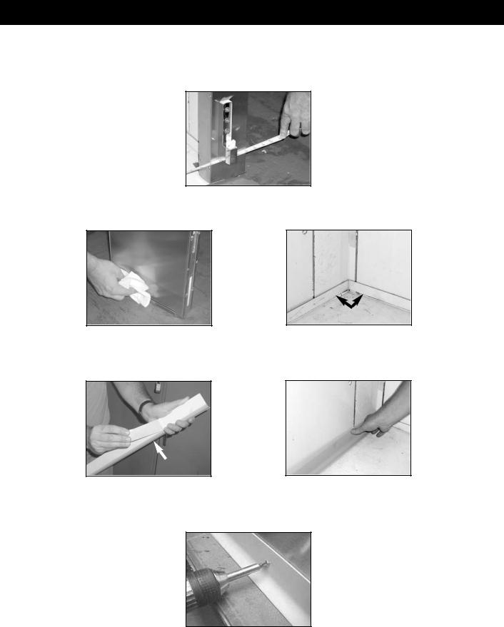
A drawing is supplied with all Proofer Cabinets to assure correct placement of Panels. Each Panel is individually marked with a number to assist with the assembly sequence. An example is shown below.
Silicone has also been provided to fill in Interior and Exterior Seams between Panels after assembly.
*Note: All cams turn clockwise unless label on panel indicates otherwise!
Item |
Part No. |
Part Description |
Qty |
1 |
P7900101 |
10” x 82” Panel, Front Left with Controller |
1 |
2 & 6 |
P7907401 |
30.5”x 82” Panel, Side Left Front/Right Rear |
2 |
3 & 7 |
P7907301 |
30.5”x 82” Panel, Side Left Rear/ Right Front |
2 |
4 |
P7905301 |
37” x 82” Panel, Rear Left |
1 |
5 |
P7905401 |
37” x 82” Panel, Rear Right |
1 |
8 |
P7900801 |
4” x 82” Panel, Front Right |
1 |
9 |
P7900901 |
6” x 60” Panel, Header with Light |
1 |
10 |
P7901001 |
34” x 74” Panel, Front Roof |
1 |
11 |
P7901101 |
31” x 74” Panel, Rear Roof |
1 |
12 |
P7903601 |
Door Assembly, RH with Horizontal Handle |
1 |
13 |
P7903501 |
Door Assembly, L H with Horizontal Handle |
1 |
14 |
P7907501 |
4-Heater Air Wash Housing Assembly |
1 |
3
APPLYING COVE MOLDING
*Note: All pictures show the protective vinyl coat on parts described in this instruction. Make sure all vinyl protective coating is removed before installing cove molding.
Tools Needed: Screw Gun, Rubbing Alcohol, Paper Towels and Measuring Tape
1. Measure Top and Bottom of Proof Box to check for proper alignment. See Figure 1.
Figure 1
2.Wipe down Proof Box Interior Wall Base Angles and Exterior Wall Bottom with Rubbing Alcohol. See Figure 2 & 2a.
interior wall base angles
Figure 2 |
Figure 2a |
3.Cut Cove Molding Strip to desired length and miter at corners where needed. Peel Paper from Adhesive Strip and apply Cove Molding to Proof Box's Interior Wall Base Angles and Exterior Wall Bottoms. See Figure 3 & 3a.
molding with adhesive |
|
Figure 3 |
Figure 3a |
4.Install #10 Stainless Steel Self-Tapping Screws into Cove Molding, Interior Wall Base Angles and Exterior Wall Bottoms. Space Screws approximately 1"(inch) up from bottom of Cove Molding, and 8" to 12" (inches) apart while avoiding Wall Seams. See Figure 4.
Figure 4
5.Repeat process until all Cove Molding is applied completely around the Proof Box's Interior and Exterior Bottom.
4

AIR-WASH SYSTEM INSTALLATION
Tools Needed : Channel Locks, Screw Gun with #2 Phillip Drive, Wire Stripper, Snips (or equivalent)
1.Make sure all Plastic Plug Buttons are placed into Cam-Lock Holes before mounting Air-Wash System.
2.At top of Air-Wash System, remove 4½"x 4½" Junction Box, Lock Nuts & Reducer Washers from CPVC Piping. Set aside for later use.
3.Remove Bottom Panel of Air-Wash System by lifting up and away with Mounted Handle. Place Bottom Panel in secure location to avoid damage. See Figure 1 & 1a.
|
|
Bottom |
|
Bottom |
|||
|
Panel |
||
Panel |
|
||
|
Removed |
||
|
|
||
|
|
|
Figure 1 |
Figure 1a |
4.Move Air-Wash System into Proof Cabinet. Place directly behind Control Panel and in front of First Left Side Wall Panel.
5.Make sure Heater Wires, Copper Water Line & CPVC Piping are aligned with Holes going through Front Roof Panel.
6.Put 4½" x 4½" Junction Box on Floor, and place centered inside Air-Wash System (*Note: 4½"x 4½" Junction Box will be used to support Back Panel of Air-Wash System. Make sure it is very close to Back Panel!). See Figure 2.
Air-Wash System placed
inside cabinet
4½"x 4½" Junction Box centered inside of Air-Wash System
Figure 2
7.Carefully lift Air-Wash System and place Heater Wires, Copper Water Line & CPVC Piping through Holes of Front Roof Panel. Rest bottom of Air-Wash System Back Panel on top of 4½" x 4½" Junction Box for support (*Note: Middle Panel under Fan Panel can also be removed for easy lift. DO NOT use Heater Elements to lift!). See Figure 3.
5

Air-Wash System lift
4½"x 4½" Junction Box placed under Back Panel of Air-Wash System
Figure 3
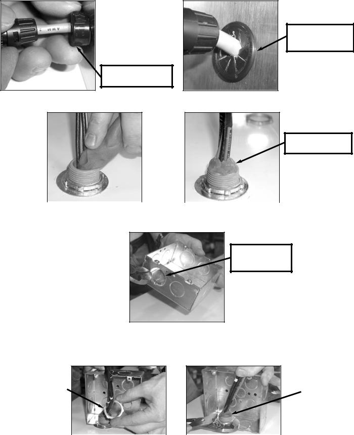
8.At top of cabinet and left side of Front Roof Panel, place Reducing Washer & Lock Nut over both CPVC Pipes. Use Channel Locks (or equivalent tool) to tighten until snug. See Figures 4, 4a & 4b.
Reducing Washer & Lock Nut applied to CPVC
Figure 4 |
Figure 4a |
Figure 4b |
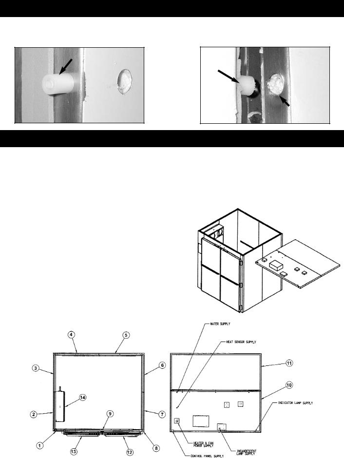
9.Starting at top of Proof Cabinet, feed Heat/Humidity Sensor Cable Plug through Copper Water Line CPVC Piping. (*Note: Can use Finger or 5" Flat Head Screwdriver to feed Cable through if needed.) See Figures 5 & 5a.
Heat/Humidity Sensor
Cable Plug fed into
CPVC Piping
Figure 5 |
|
Figure 5a |
10.After Heat/Humidity Sensor Cable Plug is placed through CPVC Pipe, feed Plug through 3/4" Hole located at Upper Right Side of Air-Wash System. (*Note: Picture below shows Air-Wash System not mounted to Proof Cabinet for visual purposes.) See Figure 6.
Cable fed through Upper
Right Side ¾" Hole or
Air-Wash System
Figure 6
6
11.Take ¾" Heyco Bushing from Accessory Kit and cut at one side with Snips (or equivalent). Place Heat/Humidity Sensor Cable Plug into ¾" Heyco Bushing, and fit ¾" Heyco Bushing to ¾" Hole at Upper Right Side of Air-Wash System. See Figures 7 & 7a.
¾" Heyco Bushing fitted flush to Air-Wash System
Cable fed through ¾" Heyco Bushing
Figure 7 |
Figure 7a |
12.Apply Putty in and around Heater Wire & Copper Water Line CPVC Piping. See Figures 8 & 8a.
Putty placed in and around CPVC Piping
Figure 8 |
|
Figure 8a |
13.Remove 4"x 4" Junction Box from bottom of Air-Wash System Back Panel. Take out 1 5/16” Knock Out from one side of 4"x 4" Junction Box. See Figure 9.
Removal of 1 5/16”
Knock Out
Figure 9
14.Feed Heater Wires and CPVC Pipe through 1 5/16” Knock Out of 4" x 4" Junction Box.
15.Place Lock Nut inside 4" x 4" Junction Box and onto CPVC Threads. Tighten until snug with Channel Locks (or equivalent tool). See Figure 10 & 10a.
Placing Lock Nut |
|
|
|
Tightening Lock Nut |
|||
inside Junction Box |
|
||
|
|
||
|
|
|
Figure 10 |
|
Figure 10a |
7
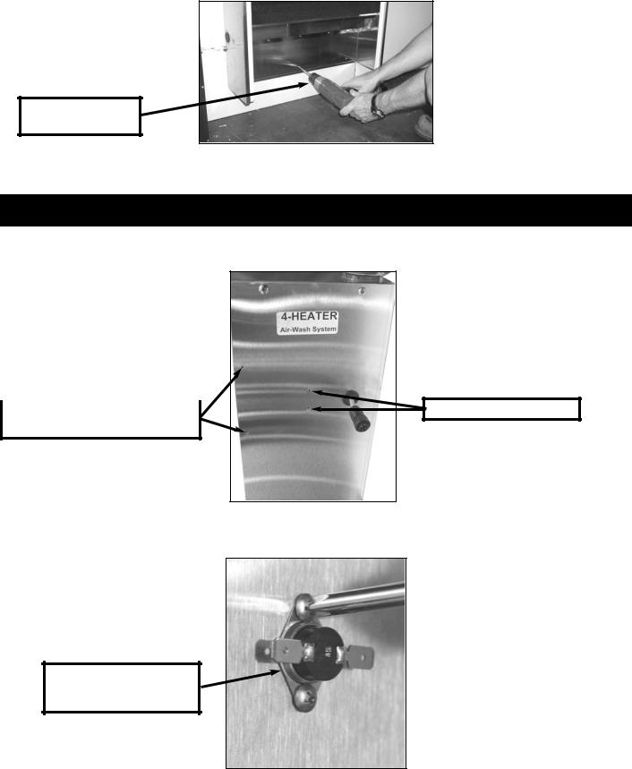
16.Secure bottom of Air-Wash System by placing three (3) #10 Stainless Steel Self-Drilling Screws. See Figure 11.
Placing Three #10
Self-Drilling Screws
Figure 11
17.To complete Air-Wash System installation, apply Bottom Panel by reversing Step #3.
SENSOR / KLIXON ASSEMBLY & INSTALLATION
Tools Needed : Phillips Head Screwdriver & Adjustable Wrench
1. Locate Sensor and Klixon Mounting Holes above the Air-Wash System Panel Fans. See Figure 1.
Holes for |
|
Holes for Mounting Klixon |
Heat/Humidity Sensor Bracket
Figure 1
2.Mount Klixon to Air-Wash System Panel. Make sure Metal Disc side of Klixon has contact with AirWash Panel. See Figure 2.
Klixon shown correctly mounted to
Air-Wash Panel
Figure 2
8
3. Mount Sensor Bracket to side of Air-Wash System Panel. See Figure 3.
Sensor Bracket Mounted
to Air-Wash Panel
Figure 3
4.Place and secure Sensor to Sensor Bracket with Screws and Lock Washer Nuts. See Figure 4 & 4a.
|
|
|
Figure 4 |
Figure 4a |
|
5.Connect Sensor Wires to Klixon, and Heat/Humidty Sensor Cable Plug into Sensor Port. See Figure 5. (*Note: Refer to page 7 and Figure 7 for Heat/Humidity Sensor Cable Plug)
Sensor Port
Figure 5
6. The Sensor and Klixon Assembly is now complete.
9
 Loading...