

Page 1
Installation, Operation and Troubleshooting Instructions
Manual Part No.: P6924600
Rev: 00
Print Date: 01/27/06
607 Industrial Way, Eatontown, NJ 07724
Phone: (800) 526-2807 Fax: (732) 544-0735 Website: www.adamatic.com
For Roll -In & Roll-Thru Models: AP-1W, AP-2W, AP- 3W
Adamatic Modular Proofers
Page 2

Thank you for purchasing an Adamatic Modular Proof Cabinet! This unit has passed
our strict Quality Control Inspection and meets the high standards set by Adamatic.
You have made a quality investment that with proper maintenance will give you years
of service.
Please read the following installation and maintenance instructions before installing or
using your unit. If you have any questions, please call our Customer Service
Department at (800) 526-2807.
IMPORTANT INFORMATION - PLEASE READ
●●
Please read these instructions carefully before installing or using. If recommended
procedures are not followed, warranty claims will be denied.
●●
Your Warranty Registration information is located on the next page of this manual. Please
complete the card and submit it to Adamatic within 10 days of installation. Failure to
properly register equipment can void the warranty.
●●
Adamatic reserves the right to change specifications and product design without notice.
Such revisions do not entitle the buyer to corresponding changes,improvements,
additions or replacements for previously purchased equipment.
●●
A detailed Owners Manual with a troubleshooting guide, parts lists and additional
information can be ordered from the factory or may be downloaded free from the website at
www.adamatic.com.
THANK YOU
Page 3

ORIGINAL DATE OF INSTALLATION __________________________________________________________________
INSTALLATION COMPANY NAME ____________________________________________________________________
STREET_______________________________ CITY _____________________ STATE ______ ZIP CODE___________
DISTRIBUTOR’S NAME_____________________________________________________________________________
STREET_______________________________ CITY _____________________ STATE ______ ZIP CODE___________
607 INDUSTRIAL WAY
EATONTOWN, NJ 07724
TEL: (800) 526-2807
● FAX: (732) 544-0735
Warranty
(Continental USA Only)
The Seller warrants to the original purchaser , equipment manufactured by Seller to be free from defects in material and
workmanship for which it is responsible. The Seller's obligation under this warranty shall be limited to replacing or
repairing at Seller's option, without charge, F.O.B. Sellers factory, any part found to be defective and any labor and
material expense incurred by Seller in repairing or replacing such part, such warranty to be limited to a period of one
year from date of purchase or thirteen months from date of shipment from Seller's factory , whichever is earlier, provided
terms of payment have been fully met. All labor shall be performed during regular working hours. Overtime premium
charges will be at Buyer's expense.
Proof of purchase must be supplied to Seller to validate warranty. This warranty is valid only if equipment is properly
installed, started-up and inspected by the dealer or authorized Adamatic Service agent.
Removal or alteration of the serial/data plate from any equipment shall be deemed to release Seller from all warranty
obligations or any other obligations, expressed or implied.
This warranty does not cover Thermostat or Defrost Timer calibration and/or adjustment, freight damage, normal
maintenance items outlined in Owner's Manual, adjustment of door mechanisms or replacement of light bulbs, fuses
or batteries.
Any repairs or replacement of defective parts shall be performed by Seller's authorized service personnel. Seller shall
not be responsible for any costs incurred if the work is performed by other than Seller's authorized service personnel.
Reimbursement claims for part(s) or labor service costs must be made in writing. Model, cabinet serial numbers and
installation location must be shown on the claim. A receipted bill from the servicing agency must accompany the claim,
together with full details of the service problems, diagnosis and work performed. Adamatic reserves sole discretion
whether further documentation on a claim is to be submitted.
Seller shall not be liable for consequential damages of any kind which occur during the course of installation of
equipment, or which result from the use or misuse by Buyer, its employees or others of the equipment supplied
hereunder, and Buyer's sole and exclusive remedy against Seller for any breach of the foregoing warranty or otherwise
shall be for the repair or replacement of the equipment or parts thereof affected by such breach.
The foregoing warranty shall be valid and binding upon Seller if and only if Buyer loads, operates and maintains the
equipment supplied hereunder in accordance with the instruction manual provided to Buyer. Seller does not guarantee
the process of manufacture by Buyer or the quality of product to be produced by the equipment supplied hereunder
and Seller shall not be liable for any prospective or lost product or profits of Buyer.
THE FOREGOING WARRANTY IS EXCLUSIVE AND IN LIEU OF ALL OTHER EXPRESS AND IMPLIED
WARRANTIES WHATSOEVER. SPECIFICALLY THERE ARE NO IMPLIED WARRANTIES OF MERCHANTABILITY
OR OF FITNESS FOR APARTICULAR PURPOSE.
The foregoing shall be Seller's sole and exclusive obligation and Buyer's sole and exclusive remedy for any action,
whether in breach of contract or negligence. In no event shall Seller be liable for a sum in excess of the purchase price
of the item.
Cabinet Model No.______________________
Cabinet Serial No. _________________
(Data plate information located inside cooler on
the upper left wall)
WARRANTIES NOT VALID UNLESS REGISTERED AT
FACTORY WITHIN 10 DAYS AFTER START-UP DATE.
Page 4
Page 5
Page 6
Page 7

TABLE OF CONTENTS
Receiving Shipment....…………………....…………………….......................................……....…. 1
Installation Guidelines..............................………………..………………………………................... 1
Floor & Wall Base Angle Installation.......................................……………………......................... 1
Cam-Locking Panels.................................………………...………………………………………….. 2
Applying Foam Tape...................................................................................................................... 2
Panel Pins...................................................................................................................................... 3
Panel Assembly ......……………………………………………......................................................... 3
Applying Cove Molding.....……………………………...…………………………………................... 4
Sensor & Klixon Assembly.....……………………………...………………………………….............. 5
Air Wash System Panel Installation............................................................................................... 6
Air Wash System Filter & Drain Pan Location............................................................................... 7
Drain Line & Rubber Coupling Assembly....................................................................................... 8
Bumper Guard Assembly............................................................................................................... 8
High Voltage Box Assembly........................................................................................................... 9
240V Interior Light Assembly (Optional)........................................................................................ 10
120V Electrical, Relay Box & Interior Light Assembly (Optional).................................................. 11
Interior Light Bulb & Globe............................................................................................................. 14
Flashing Indicator Alarm Assembly................................................................................................ 14
Air Wash System 4 x4 Junction Box, Fan Motors, Heaters.......................................................... 15
Solenoid & Water Line Extension Assembly.................................................................................. 17
1, 2 & 3 Rack Proof Cabinet Top View........................................................................................... 19
Power Module Cable Configuration............................................................................................... 20
Power Module Circuit Breaker & Fuses......................................................................................... 20
Top Facade Assembly.................................................................................................................... 20
Door Closer Assembly.................................................................................................................... 21
Door Assembly .................................................................................................................. ............. 21
Door Handle & Guard Assembly....................................................................................................23
Door Adjustment Instruction........................................................................................................... 24
Special Shims for Hinged Door Adjustment................................................................................... 24
Door Gasket Replacement............................................................................................................ 25
Installation Check List.................................................................................................................... 25
Periodic Maintenance.................................................................................................................... 25
Proofing System & How It Works.................................................................................................. 26
Disconnect Switch.......................................................................................................................... 26
Control Panel & How It Works....................................................................................................... 26
Troubleshooting (for the Service Technician Only!)....................................................................... 28
Technical Service Support & Replacement Parts.......................................................................... 28
Common Replacement Parts......................................................................................................... 29
Wiring Diagram.............................................................................................................................. 30
Page 8

1
All units are performance tested and thoroughly inspected prior to shipment. Upon receipt, examine
the exterior of the shipment packaging for any signs of rough handling. If the cabinet is damaged, it
should be noted on the delivery slip or bill of lading and signed. A claim must be filed immediately
against the carrier indicating the extent and estimated cost of damage incurred.
Proper installation is the first step to operation. We recommend that your proofer be installed
by an authorized Adamatic Certified Installer.
Locating Your New Proofer
Consider the following when selecting a location for your proofer:
1. Clearance - There must be a minimum clearance of 24” (inches) between the top of the proofer
and the ceiling.
2. Floor Load - The floor on which the cabinet will rest must be free of vibration and suitably strong
enough to support the combined weights of the cabinet plus the maximum product load.
*Note: All pictures show the protective vinyl coat on parts described in this instruction document.
Make sure all vinyl protective coating is removed before installation. Same method of
installation applies to Floorless Proof Boxes with Wall Base Angles only.
T
ools Needed: Drill with ¼" (inch) Masonry Bit, Tubes of Silicon, Dynabolt Anchors, Screw Driver, & Trowel
1. Find location to assemble proof cabinet. Before assembly, make sure designated floor area and
neighboring wall space is level, clean and free of any obstruction.
2. If supplied, place Stainless Steel Floor on appointed floor space and mark along the edges.
(*Note: Same method of installation applies to Floorless Proof Boxes with Wall Base Angles only!)
3. Remove Stainless Steel Floor and apply beads of Floor Adhesive along the bottom while properly
spreading with Trowel. Make sure the bead is continuous around the edge of Stainless Steel Floor.
4. Seat Stainless S teel Floor over designated floor space and lightly walk on the Floor . Put still weight
on the Stainless Steel Floor so that Adhesive will keep in required contact with Floor beneath (i.e.
weights, boxes with weight, etc).
5. Place Wall Base Angles around the edge of Stainless Steel Floor. Make sure that holes located at
ends of the Wall Base Angles align over the holes in Stainless Steel Floor.
6. Drill Floor Holes through the Wall Base Angles with a 1/4" diameter drill bit for placement of
Concrete Floor Anchors.
●●
Mark drill bit at 1-1/2" (inches) from the end. Drill until mark is aligned with the top of the St ainless
Steel Floor. Do not drill beyond the mark on the drill bit!
●●
Clear concrete dust from holes. (*Note: all debris from drilling must be removed before
installation or Anchors will not work!)
●●
If proof cabinet is mounted on stone or ceramic tile, extend holes and Anchors into concrete
substrate.
FLOOR & WALL BASE ANGLE INSTALLATION
INSTALLATION GUIDELINES
RECEIVING SHIPMENT
Page 9
7. Install Anchors in the holes of Wall Base Angles and set in place.
T
ools Needed
: Allen Wrench (*supplied with accessories)
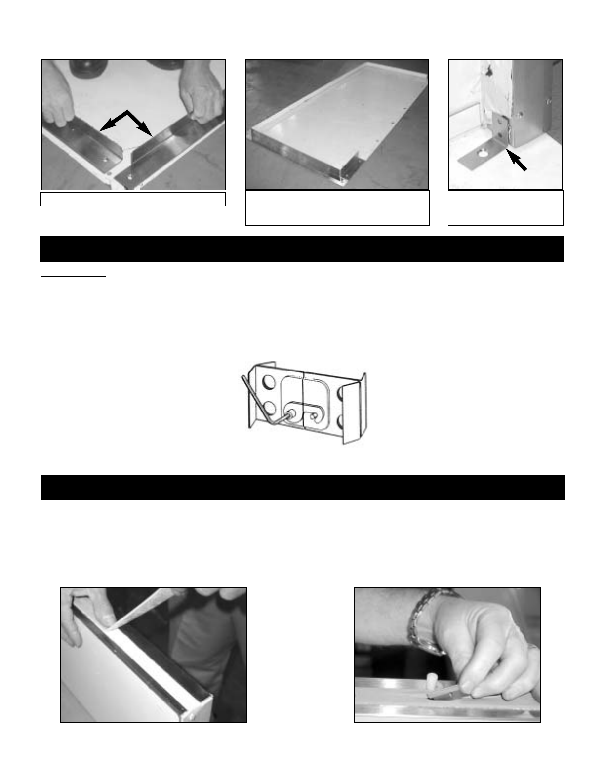
All Proofer Cabinet Panels are joined together by Cam-Locks. Panel sections lock together from inside
the Proofer Cabinet to provide accurate tight joining. Always align top edges and inner face of Panels
as you lock them together.
*Note: From inside Proofer Cabinet, all Cams turn clockwise with exception of inner left hand side of
Header that turns counter-clockwise. All Male Cam direction of turn is marked on required
panels.
3/4” Wide Foam Tape has been provided for Proof Cabinet Panel sealing. Foam Tape should be
placed over Foam Insulation of all Panel Edges with Male Cams. See Figure 1.
Once Foam Tape has been applied to Panel, cut Slit at all Male Cam locations. See Figure 2.
*Note: Only one strip of Foam Tape should be placed in between Panels. This will guarantee proper
Seal and Cam Locking.
Figure 1 Figure 2
CAM-LOCKING PANELS
APPLYING FOAM TAPE
2
Wall Base Angles
Optional Floor with Wall Base Angles Assembled
*Note: Floor shown with vinyl for clarity.
Remove before assembling!
Floor Anchor Placed at
end after checking Corner.
Illustrations show cam-lock panel mechanism from
inside the proofer cabinet.
Page 10
3
PANEL ASSEMBLY
PANEL ALIGNMENT PINS
Item Part No. Part & Cam-Locking Description Qty
1 P7900101 10” x 82” Front Wall Panel w/ Control 1
2 P7900201 10” x 82” Wall Panel (Male/Male) 2
3 P7900301 10” x 82” Wall Panel (Female/Male) 4
4 P7900401 10” x 82” Rear Wall Panel (Female/Male) 1
5 P7900501 10” x 82” Rear Wall Panel (Female/Female) 1
6 P7900601 27” x 82” Wall Panel (Female/Male) 2
7 P7900801 4” x 82” Front Wall Panel (Female/Female) 1
8 P7900902 6” x 60” Header Panel without Light 1
9 P7902101 12” x 74”, Front Roof Panel 1
10 P7902201 12” x 74”, Rear Roof Panel 1
11 P7902601 10” x 74”, Center Roof Panel 1
12 P7903501 LH Door Assembly with Horizontal Handle 1
13 P7903601 RH Door Assembly with Horizontal Handle 1
14 P6900048 3-Heater Air Wash Housing Assembly 1
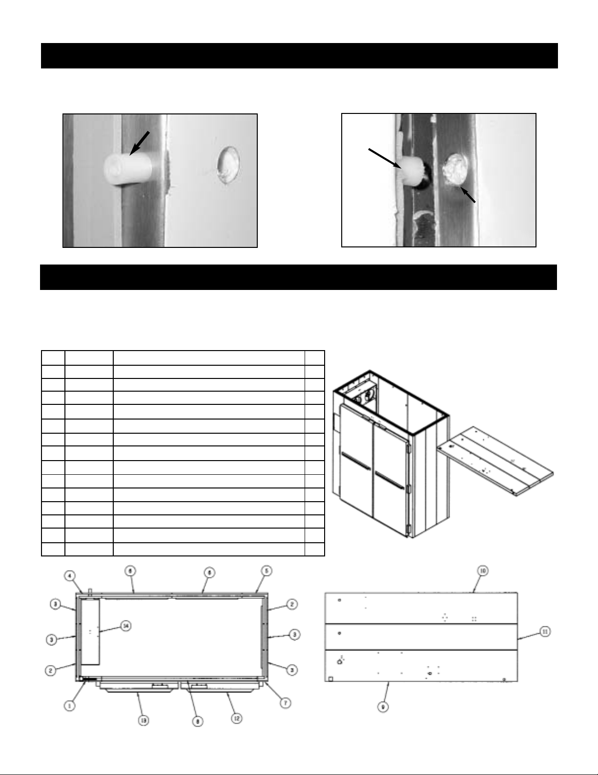
A drawing is supplied with all Proofer Cabinets to assure correct placement of Panels. Each Panel is
individually marked with a number to assist with the assembly sequence. An example is shown below.
Silicone has also been provided to fill in Interior and Exterior Seams between Panels after assembly.
Panel Alignment Pins have been supplied with your Proof Cabinet and are placed on Panel sides with
Male Cams only. Pins support easy alignment and allow Male Cams to properly catch into Female
Cams.
Panel Alignement Pin
Hole for Pin
Pin
Page 11
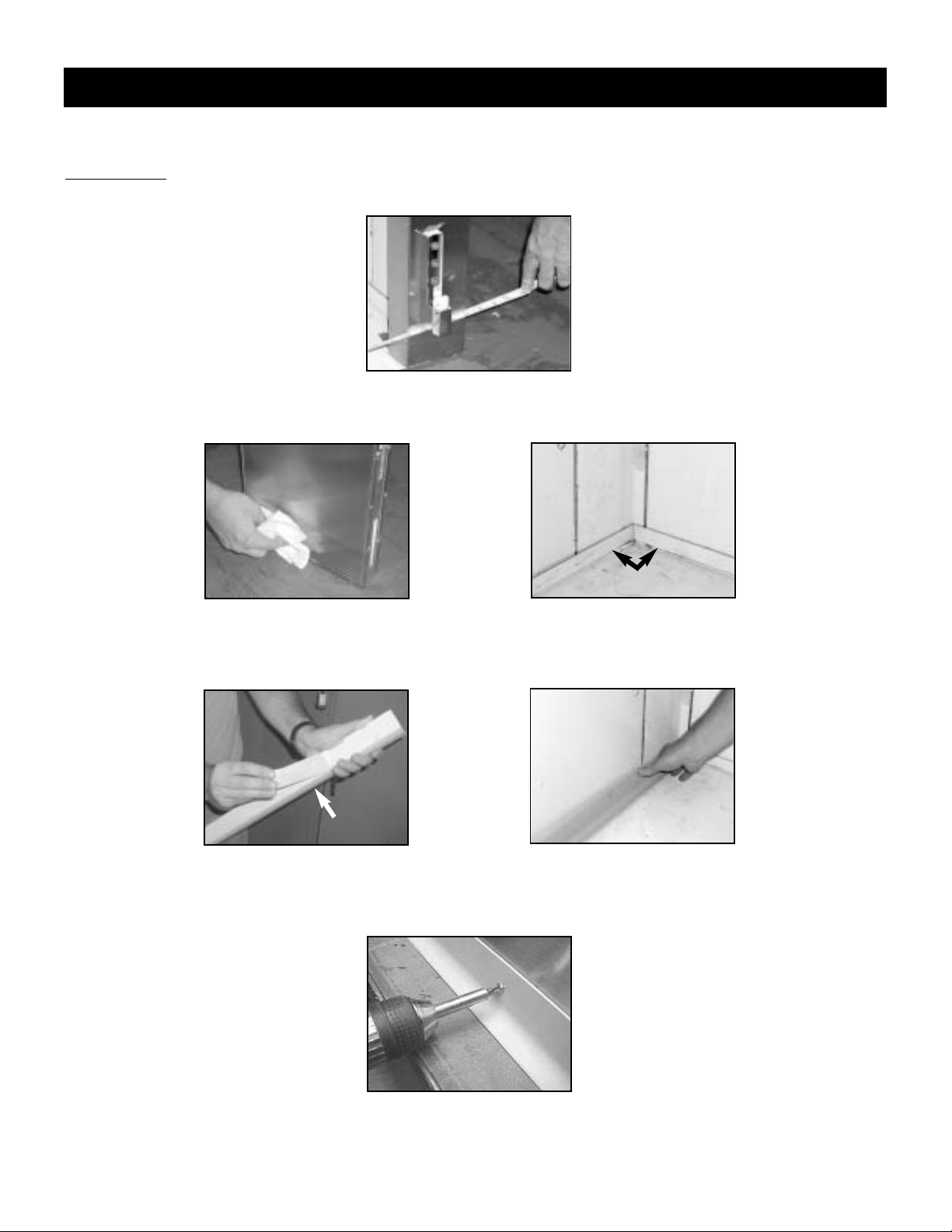
*Note: All pictures show the protective vinyl coat on parts described in this instruction. Make sure all
vinyl protective coating is removed before installing cove molding.
T
ools Needed: Screw Gun, Rubbing Alcohol, Paper Towels and Measuring Tape
1. Measure Top and Bottom of Proof Box to check for proper alignment. See Figure 1.
Figure 1
2. Wipe down Proof Box Interior Wall Base Angles and Exterior Wall Bottom with Rubbing Alcohol.
See Figure 2 & 2a.
Figure 2 Figure 2a
3. Cut Cove Molding Strip to desired length and miter at corners where needed. Peel Paper from
Adhesive Strip and apply Cove Molding to Proof Box's Interior Wall Base Angles and Exterior Wall
Bottoms. See Figure 3 & 3a.
Figure 3 Figure 3a
4. Install #10 Stainless Steel Self-Tapping Screws into Cove Molding, Interior Wall Base Angles and
Exterior Wall Bottoms. Space Screws approximately 1"(inch) up from bottom of Cove Molding, and
8" to 12" (inches) apart while avoiding Wall Seams. See Figure 4.
Figure 4
5. Repeat process until all Cove Molding is applied completely around the Proof Box's Interior and
Exterior Bottom.
4
APPLYING COVE MOLDING
interior wall base angles
molding with adhesive
Page 12
5
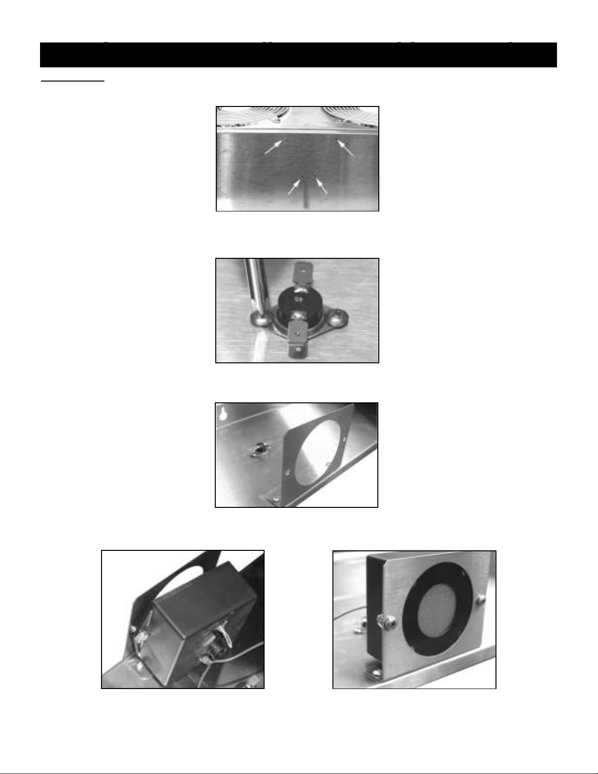
Proofer Sensor & Klixon Assembly Procedure
Tools Needed : Phillips Head Screwdriver & Adjustable Wrench
1. Locate Sensor and Klixon mounting holes above the Air Wash System Panel Fans. See Figure 1.
Figure 1
2. Mount Klixon to Air Wash System Panel making sure metal side is face down. See Figure 1 & 2
Figure 2
3. Mount Sensor Bracket to Air Wash System Panel. See Figure 1 & 3.
Figure 3
4. Place and secure Sensor to Sensor Bracket with Screws and Lock Washer Nuts. See Figure 4 & 4a.
Figure 4 Figure 4a
SENSOR & KLIXON ASSEMBLY
Page 13

5. Place Wires from the Sensor on to the Klixon. Se e Figure 5.
Figure 5
6. The Sensor and Klixon Assembly is now complete and should look like Figure 6 below.
Figure 6
T
ools Needed : Phillips Head Screwdriver
The Air Wash System Panel is to be mounted on the 10”x 82” and 41”x 82” Panel. The designated Panel has
holes located at the top and bottom that will t ake the #10 Screws supplied. Key Hole Slot s on the Air Wash
Panel for mounting are located at the top and close to the bottom covered by the Bumper Drain
Guard.
AIR WASH SYSTEM PANEL INSTALLATION
6
*Note: When mounting Air Wash System
to Proof Box Wall, make sure that
Fans & Water Line are in upright
position as shown in picture.
*Note: Make sure the Lower Front Panel’s
cut-out is always at the very
bottom. If cut-out is positioned up
side down, this will cause proof
box to work incorrectly. See page
7 for close view.
Page 14

Tools Needed : Drill with Phillips Head Bit
1. Take out Screws from Bottom Panel of Air Wash System. Remove Bottom and Middle Panels as
shown. See Figure 1 & 1a.
Figure 1 Figure 1a
2. Carefully remove Filter and Carrier. Change Filter if necessary. See Figure 2.
Figure 2
3. Reverse steps to reapply Filter.
Note: Drain Pan is located at very bottom of Air Wash System. See Figure 3
figure 3
AIR WASH SYSTEM FILTER & DRAIN PAN LOCATION
7
Drain Pan
Page 15

Tools Needed : Flat Head Screwdriver
1. Put Drain Line through the hole located at the bottom of the Rear Corner Panel from inside the
proofer cabinet
2. Assemble Rubber Coupling with Adjustable Clamps and Drain Line to Drain Stub. Tighten
Adjustable Clamps until snug.
3. Extend Drain Line to Floor Drain.
*Note: Picture shows Air Wash Panel not mounted to proofer cabinet. Drain Line Assembly should be done when the Air
Wash Panel is mounted to the cabinet.
Tools Needed : Drill with Phillips Head Bit
Bumper Guards are to be applied with #10 Self Tapping Screws. All hardware has been supplied with
the accessory kit. Pre-drilled holes are placed on the airwash system panel. Use the Airwash System
Panel Guard as a guide to place additional interior Bumper Guards.
8
DRAIN LINE & RUBBER COUPLING ASSEMBLY
Rubber Coupling
Drain Line
Drain Stub
BUMPER GUARD ASSEMBLY
Bumper Guards
Page 16

Tools Needed : Drill with Phillips Head Bit
1. Mount 4”x 4” Junction Box at upper right side of Proof Box with supplied Tapping Screws. Apply
Strain Relief with Lock Nut to side of Junction Box closest to Power Module. Refer to “TOP
VIEW” on page 18 for approximate placement. See Figure 1.
Figure 1
2. Take Power Module High Voltage Wires with Ground and put through Flexible Conduit. See
Figure 2.
Figure 2
3. Secure Flexible Conduit into Power Module Strain Relief. See Figure 3 & 3a.
Figure 3 Figure 3a
HIGH VOLTAGE BOX ASSEMBLY
4” x 4”
Junction Box
Lock Nut
Flexible
Conduit
High Voltage Wires
& Ground
Power Module
Strain Relief
Flexible Conduit
Secured Conduit
Plastic Strain
Relief
9
Page 17

4. Take opposite side of Flexible Conduit with exposed High Voltage and Ground Wire; feed
through Strain Relief of 4”x 4” Junction Box. See Figure 4.
Figure 4
5. Secure Flexible Conduit into Strain Relief. Make sure enough High Voltage and Ground Wire to
connect to Main Power Supply High Voltage Wire is available. A Metal Strain Relief has been
supplied for Main Power Supply wire feed. See Figure 5.
Figure 5
T
ools Needed : Wire Nuts (*supplied with accessories)
1. Place Interior Light Cable into Connection above Main Power Supply Wires. Cut notch on 3/4”
Bushing so that it can fit around Cable. See Fig 1 & 1a
Fig 1 Fig 1a
240V INTERIOR LIGHT ASSEMBLY (OPTIONAL)
Metal Strain Relief
10
Interior Light
Cable
Main Power Supply Wires
Page 18

2. Locate Interior Light Wires coming through Header Panel and feed through Roof Panel. See Fig 2
Fig 2
3. Wirenut Interior Light Cable to Interior Light as follows:
Interior Light Cable
Interior Light
Red Wire to White Wire
Black Wire to Black Wire
White Wire to Green Wire
120V Electrical & Relay Box Assembly” “Interior Light Assembly”
Tools Needed : Wire Nuts & Tapping Screws (*supplied with Assembly), Electrical Tape, Drill with Phillips Tip
1. Run Wires from the Interior Light Assembly through the Bottom Hole of Relay Box Assembly
before mounting. See Figure 1.
120V ELECTRICAL/RELAY BOX & INTERIOR LIGHT ASSY (OPTIONAL)
Light Cable
120V Electrical Box
Relay Box
11
Page 19

12
Figure 1
2. Mount 120V Relay & Electrical Box in designated locations and secure with supplied #10 Screws.
Make sure Relay Box Bushing is placed into the Hole for Interior Light Wire run. Refer to page 18
“Proofer Top View” and see Figures 2 & 2a below.
Figure 2 Figure 2a
3. Wire the Interior Light, 120V Electrical/Relay Box, and Light Cable according to the Wiring
Diagram. Make sure all Green Wires (Grounds) are properly secured. Ensure that White 14
Gauge Wires are connected with supplied Wire Nut. See Figures 3, 3a & 3b with comments.
Figure 3
“Secure Ground Wires”
Figure 3a
“Connect 14 GA Black Wire with
Insulated Push On Terminal To Open
Relay Terminal”
Figure 3b
“Connect (2) 14 GA White Wires
Together Using Supplied Wire
Nut”
Page 20

4. Place Light Cable coming from Relay Box into desginated area on Power Module. See Figure 4.
Figure 4
5. 120V/60Hz/1Ph Electrical Supply should be ran into the 120V Electrical Box by a qualified
electrician in accordance with local electrical codes. Figure 5.
Figure 5
6. Seal Hole between bottom of Relay Box and Roof Panel with Silicone. See Figure 6.
Figure 6
13
Page 21

7. Place Covers on Relay and Electrical Box after all wiring has been completed. See Figures 7 & 7a.
Figure 7 Figure 7a
Place Light Bulb and Globe once wiring of the Interior Light is complete.
T
ools Needed : Flathead Screwdriver (*to clear foam insulation if needed)
1. Connect Proofer Cycle Indicator Light Cable to Power Module Connection. See Figure 1.
Figure 1
14
FLASHING INDICATOR ALARM ASSEMBLY
Proof Cycle
Indicator Light
Cable
INTERIOR LIGHT BULB & GLOBE
Page 22

2. Place 3/4” Bushing on to Cable. Cut notch on Bushing so that it can fit around Cable. See Figure 2.
Figure 2
3. Starting at Pre-Drilled Hole at top right side of cabinet, feed cable down through Rectangular Hole
located at top right corner. See Figure 3.
Figure 3
4. Plug Cable Connections to the back of the Flashing Indicator Alarm Lamp. Red Wire plugs into
Positive (+) Connection & Black Wire plugs into Negative (-) Connection on back of Lamp. Secure
Lamp in Rectangular Hole when wiring connection is complete. See Figure 4.
Figure 4
T
ools Needed : Drill with Phillips Tip
4 x 4 Junction Box
1. Feed Air Wash System Fan and Heater Wires through Top Left Front Corner of Roof Panel. See
Figure 1.
Figure 1
15
AIR WASH SYSTEM 4 x 4 JUNCTION BOX, FAN MOTORS, HEATERS
Left Rear Knock Out
Fan & Heater
Wires
Page 23

2. Remove left rear Button Knock Out on 4” x 4” Junction Box as shown. Install Bushing and mount
Junction Box using supplied screws. See Figure 2.
Figure 2
Air Wash Heater Connections
3. Remove Right Side Front Knock Out on Junction Box.
4. Install Straight Strain Relief on Black Supply Cable.
5. Insert Black Supply Cable and Straight Strain Relief through Knock Out. Inst all Lock Nut and tighten.
See Figure 3.
Figure 3
6. Connect Heater Lead “L1” 10 Gauge Wire to Black 10 Gauge Wire using supplied Wire Nut.
7. Connect Heater Lead “L2” 10 Gauge Wire to Red 10 Gauge Wire using Supplied Wire Nut.
8. Connect Heater Lead “L3” 10 Gauge Wire to Black 10 Gauge Wire using supplied Wire Nut.
9. Connect Heater Green Grounding Lead to 10 Gauge Green Wire using supplied Green Wire Nut.
Air Wash Fan Motor Connections
10. Remove Right Side Front Knock Out on Junction Box.
11. Install Straight Strain Relief on Gray Fan Cable.
12. Insert Cable and Strain Relief into Knock Out. Install Lock Nut and tighten.
13. Connect Fan Lead Black #14 Gauge Wire to Black #20 Gauge Wire using Supplied Wire Nut.
14. Connect Fan Lead Red #14 Gauge Wire to Red #20 Gauge Wire using supplied Wire Nut.
15. Connect Fan Lead Grounding Green #14 Gauge Wire to Grounding Green #20 Gauge Wire using
supplied Wire Nut.
16
Knock Out
Strain Relief
Page 24

16. Carefully inspect each Wire Nut connect for proper installation. See Figure 4.
Figure 4
17. Seal Hole for Air Wash Wiring with Silicone. See Figure 5.
Figure 5
18. Carefully place Wires inside of Junction Box and install Cover. See Figure 6 & 6a.
Figure 6 Figure 6a
“Solenoid & Water Line Assembly”
Tools Needed : Drill with Phillips Tip
1. Plug end of Solenoid Valve Cable into designated area on Power Module. See Figures 1 & 1a.
17
SOLENOID & WATER LINE EXTENSION ASSEMBLY
Page 25

Figure 1 Figure 1a
2. Feed Water Line Extension Assembly Union Fitting through Heyco Bushing on second Roof
Panel. The Union Fitting will line up with Flare Nut on Air Wash System for proper connection.
Refer to Panera Top View on page 18. See Figures 2 & 2a.
Figure 2 Figure 2a
3. After connecting Union Fitting to Air Wash System, get Solenoid Valve Assembly and connect
Water Line Extension Flare Nut. Mount Solenoid Valve Assembly to Roof Panel by placing Tapping
Screws. See Figures 3 & 3a.
Figure 3 Figure 3a
4. Take Female End of Solenoid Valve Cable and plug onto Solenoid Valve. Secure Female End by
tightening Screw with Flat Head Screwdriver. See Figures 4 & 4a.
Figure 4 Figure 4a
18
Solenoid Valve
Cable
Solenoid Valve
Cable
Page 26

19
5. After all Proof Box assembly is complete, connect Water Supply Line to Solenoid Assembly. Make
sure that Ball Valve is in “ON” position before putting Proof Box into operation. See Figure 5.
Figure 5
Ball Valve
Water Line Connection Fitting
1 RACK NARROW PROOF CABINET TOP VIEW
2 & 3 RACK PROOF CABINET TOP VIEW
Page 27

Tools Needed : Drill with Phillips Head Bit
Assemble the Facade on top of the proofer cabinet in the sequence shown below. Use the 5/8” Self
Tapping Screws that have been supplied.
T
ools Needed : Phillips Head Screwdriver
If Proof Box does not power up and Main Power Supply is good, shut off Main Power and turn Power
Module Disconnect Switch to “OFF” position. Remove 8 Screws at Plate beside Disconnect Switch
and check Circuit Breaker and Fuses. Reverse steps to properly resupply power to Proof Box.
20
TOP FACADE ASSEMBLY (OPTIONAL)
POWER MODULE CABLE CONFIGURATION
POWER MODULE CIRCUIT BREAKER & FUSES
Control Panel
Cable
Fan Motor
Cable
Solenoid
Valve
Cable
Main
Power
Supply
Main Power
Supply To
4x4 Box
Heat/Humidity
Sensor Cable
Proof Cycle
Indicator Light
Cable
Fuses
Disconnect
Removing Plate
Screws
Circuit
Breaker
Switch
1
2
Item Part No. Part Description
1 P6014301 Grill, 1 Rack Proof Box Upper
1 P6025800 Grill, 2 Rack Proof Box Upper
1 P6028900 Grill, 3 Rack Proof Box Upper
2 P6021400 Panel, LH/RH 8” Upper End
3 50692301 Screw, 8 x 5/8 HH (Not Shown)
Page 28

21
Tools Needed : Soft Mallet (or equivalent)
1. Locate Door Closer Mounting Base on top of Door. See Figure 1.
Figure 1
2. Apply Door Closer to Door Closer Mounting Base by starting with Lip side first. If needed, use a
soft mallet or equivalent to tap Door Closure on to the Mounting Base. See Figure 2, 2a & 2b
Figure 2 Figure 2a Figure 2b
3. Door is now ready to be assembled to the proofer cabinet.
T
ools Needed : Phillips Head Screwdriver
1. Place Hook(s) on front of Cabinet Header. (*Note:The Header is the same panel that supports the
Interior Light) See Figure 1.
Figure 1
Door Closer
Door Closer Mounting
Door Closer Properly Mounted
Lip
DOOR CLOSER ASSEMBLY
DOOR ASSEMBLY
Page 29

2. Locate three (3) Door Hinge Bases on Door Jamb. See Figure 2.
Figure 2
3. Carefully take Door(s) and insert all three (3) Hinge Barrels inside Nylon Cam of Hinge Base. Have
Door(s) open at 90° or more when placing Door(s) on to the Door Jamb. See Figure 3 & 3a.
(Note: If door does not easily drop into nylon cams, remove middle hinge barrel. After top and bottom hinge barrels
have been seated into nylon cams, install middle hinge barrel)
Figure 3 Figure 3a
Hinge Barrel
Hinge Base
Nylon Cam
22
Hinge Base & Cam
Page 30

4. After placement of Door(s), check Closer Lip to make sure it properly seats into Hook when closing
Door(s). Put Hinge Covers on all three (3) Hinges to complete assembly. See Figure 4, Figure 4a
& 4b
Figure 4 Figure 4b
Put on Door Handle(s) with 1/4 x 20 Hex Bolt & Lock Washers and Interior Guard(s) with #10 SelfTapping Screws. (*Note: All Doors are shipped with Mounting Holes for easy assembly!)
Hinge
Hinge Cover
Closer Lip
Hook
23
Closer Lip
Figure 4a
DOOR HANDLE AND GUARD ASSEMBLY
Guard
Door Handle
Page 31

Tools Needed : Phillips Head Screwdriver
When adjustment of the Door Gasket seal or alignment is desired, fine-tuning can be accomplished
with the Adjusting Plate (pn 50520104). Check the instructions that follow.
1. Open the door between 90° to 180° and lift the door from the Hinge Brackets (pn 50520103).
2. Slide off the Hinge Cover(s) (pn 50520105) by grasping and pulling in a downward direction.
3. Replace the Door on the Hinge Brackets and close.
4. Locate the Adjusting Plate (pn 50520104) inside of the Hinge Barrel (pn 50520102) of choice.
The Hinge Barrel is placed on the Door itself and attached with at least two Screws (pn 50678801).
5. Loosen the Screws without taking them completely out.
6. Close Door and adjust to the Fascia of the cabinet.
7. Slowly push or pull the door until the Gasket properly aligns and evenly seals to the Cabinet
Fascia.
8. Tighten Screws on the Hinge Barrel.
9. Place Hinge Covers.
There are a couple of Special Feature Shims that assist with the adjustment of Hinged Doors using
the Self-Closing Hinge Assembly (pn 10685101). These items can be used as a second or third option
if additional adjustment is required. Refer to the Shim descriptions below and their purpose.
1. Fascia Shim (pn 05072701) - The Fascia Shim is used to help extend the “Hinge Bracket” (pn
50520103) in a forward direction when the Door Gasket needs to be loosened from or accurately
tightened to the Cabinet Fascia.
DOOR ADJUSTMENT INSTRUCTION
SPECIAL SHIMS FOR HINGED DOOR ADJUSTMENT
24
Page 32

When using this Shim, build-up the Hinge Bracket by inserting one at a time until the forward extension
supports an acceptable Gasket Seal to the Cabinet. Hinge Bracket adjustments can be different from
door to door.
Make sure that the open end of the slot shaped cut-out is always facing towards the Door.
2. Leveling Shim (pn 50538601) - The Leveling Shim is used to raise the Door in and up or down
direction. This part is placed behind the the Hinge Barrel (pn 50520102) with the open ends of the
three slot shaped cut-out’s facing towards the Cabinet. While adjusting the top or bottom Screws
per Hinge Barrel, the Door will go in a specific direction.
a.) Top Hinge Barrel with Leveling Shim - Adjusts the Door in a downward direction.
b.) Bottom Hinge Barrel with Leveling Shim - Adjusts the the Door in an upward direction.
*Note: When inserting and/or adjusting the Leveling Shim, avoid taking the Screws completely out of
the Door. Try to make a gap wide enough to slip the Shim in between the Hinge Barrel and the
Door, then tighten the Screws until the leveling process of the Door is satisfactory and stable.
Removing
Beginning at one corner, pry gasket loose from the retaining strip. Peel remainder of gasket from the
door and discard.
Replacing
Before replacing, be sure the gasket and door are at room temperature. If necessary, soak the
gasket in warm water to make it more pliable. Align new gasket frame on the door retainer strip.
Starting at one corner, press each corner of the gasket into the retainer strip. Once started, the
gasket can be easily inserted around the entire perimeter of the door by simply press rolling into
place.
After the cabinet has been installed, leveled and cleaned as described, refer to the following checklist
prior to start-up.
Check for proper electrical hook-up.
Check that cabinet is level.
Check drain line to make sure it is free of kinks and restriction.
Cabinet Cleaning
Adamatic recommends periodic internal and exterior cleaning as outlined below. Use non-abrasive
cleaners that do not contain chlorine and a soft cloth or sponge. Do not use steel wool, scrapers, wire
brushes or other harsh items to clean your proofer.
Daily Exterior Cleaning
1. Clean surface with a sponge and cleaning solution.
2. Polish with a soft cloth for stainless steel, wiping with the grain of the metal.
3. Once a week wipe with a film cutting agent to maintain shine and stainless steel finish.
Weekly Interior Cleaning
1. Turn proofer cabinet “OFF”.
2. Remove loose particles from interior floors, walls and ceiling.
3. Scrub all interior surfaces with warm detergent solution 100 °F - 120°F (38°C - 39°C) and a
nylon bristled brush.
4. Rinse with clear water and allow to air dry.
5. Remove filter and clean. Replace filter if necessary.
6. Turn proofer cabinet “ON”.
INSTALLATION CHECKLIST
PERIODIC MAINTENANCE
25
DOOR GASKET REPLACEMENT
Page 33

All proofers are supplied with a top mounted power module that includes a
"disconnect switch". The disconnect switch is the simplest way to cut off and
restore power to the proofer's working components and control board circuitry.
Common practice is to always disconnect power from the main power
source!
Start-Up
On top of the cabinet, make certain that the main power module is in the “ON” position
(*see above) . Press the main power “ON/OFF” button on the control panel and a LED and digital
alarm test will take place.
After the testing stage is complete, the controller will recall all previous settings. (*Note: if cabinet loses
power from main source, previous settings will still be recalled)
At this point, a ten minute pre-heat cycle will begin. The heat will run at the set temperature for ten
minutes prior to the humidity starting. This allows for the proof box to heat and warm the interior walls
alleviating moisture running to the floor.
26
1. Fans distribute air directly
through heaters causing
heated air effect.
2. Heated air goes through
mist water spray while
picking up moisture. Large
water drops are caught by
the air filter.
3. Hot moist air is sent
throughout proofer box.
Proofing cycle continues
repeatedly until programmed
time expires.
DISCONNECT SWITCH
PROOFING SYSTEM & HOW IT WORKS
“Disconnect Switch”
CONTROL PANEL & HOW IT WORKS
Page 34

27
How to Set Temperature & Humidity
As long as the proofer cabinet is “ON”, the control system will maintain the proofer’s internal
temperature and humidity set points. Temperature and Humidity settings can be adjusted by using the
!(up) and "(down) keys located on the controller next to the corresponding display.
The internal temperature set point can be adjusted from 40°F to 120°F, and the internal humidity set
point from 20% to 95%. To change the displayed temperature from Fahrenheit to Celsius or Celsius to
Fahrenheit, press both !(up) and "(down) keys at the same time located by the “SET
TEMPERATURE” display.
Checking Humidity Set Point
To verify the actual humidity currently in the proof box, follow these instructions:
Next to the “TIME SET” display, depress the !(up) arrow
once, depress the "(down) arrow twice, and depress the
!(up) arrow once more. The “SET HUMIDITY” and “SET
TEMPERATURE” displays will flash showing the actual
temperature and humidity inside the proof box. The controller
resets back to normal state after approximately two minutes.
(*Note: humidity readings are very sensitive to door openings
and product entry. Take reading only after doors have been
closed for an extended period of time.)
Setting Timer
The controller has the ability to run up to six timer programs.
To set proofing times, press the !(up) and "(down) keys next
to the “TIME SET” display to choose from Rack 1 thru 6.
When the correct rack number appears, use the !(up) and
"(down) keys next to the “PROOFER TIME” display to set
the amount of time in hours and minutes that you would want
the displayed rack to proof.
To activate the countdown timer, press the start button
underneath the proof timer (*when timer is running, the colon
between hours and minutes will flash). To see the time for
each rack, press the !(up) and "(down) keys next to “TIME
SET” to verify the time left on that numbered rack.
When the time has expired for a particular rack, the buzzer
will sound, the lights on the display will flash as well as the
indicator light at the upper right corner of the proofer box. The
rack whose time has expired will show in the time display
LED. Hit the “STOP” button to turn off timer. (*Note: when
pressing the “STOP” button, it will only stop the rack
displayed in the “TIME SET” LED. The remaining rack timers
will continue to run.)
Error Codes
Should any error code appear on the display, depress the “MAIN POWER” button on control panel to
“OFF”. Wait 5 minutes and turn proofer cabinet back on. Should error code again appear, call for
service.
Shut-Down
The shut-down is initiated by depressing the power key while in the “ON” state. A dry out stage will
begin consisting of a ten minute period where the fans continue to run and the internal temperature is
held at set point. The humidity will be “OFF” during this period to allow the box to dry out. At the end
of the ten minute dry out cycle, the box will go into a five minute cool down phase to reduce the heat
inside the proofer. At the conclusion of the cool down phase, the box will automatically shut down.
Page 35

Adamatic strives to provide excellent customer service along with quality equipment. To help us better
assist you, a serial number and/or model number must be provided when contacting the technical
service or parts department. The data plate is located inside the proofer cabinet on back of the
controller’s corner panel. All serial numbers are recorded and kept indefinitely.
Although common replacement parts have been presented throughout this manual, it is best to contact
Adamatic to confirm the replacement part of choice.
28
TROUBLESHOOTING
Caution: This information is for Service Technicians! Disconnect Power Supply Prior to Attempting Any Service!
Error Message & Probable Cause Table
Heater Timeout
Error Code: “ERR 1“
*Sensor calling for
heat more than 60
minutes
High Internal T emp.
Error Code: “ERR 3“
*Sensor finding
internal cabinet
temperature 15ºF than
set point with no
decrease in internal
temperature for more
than 10 minutes
Keypad Error
Error Code: “ERR 5“
*System detected a
depressed key when
power is initially
applied to the unit
Sensor Comm.
Error Code: “ERR 6“
*Sensor Board has
stopped transmitting
data for more than 30
seconds
Thermal Overload
Error Code: “ERR 7“
*Sensor finding a
tripped thermal
overload switch
Sensor Timeout
Error Code: “ERR 8“
*Sensor board not
sending data 35
seconds or more
Most Probable Causes:
1. Proofer Door open
Most Probable Causes:
1. Defective
Temperature Sensor
Most Probable Causes:
1. Someone is
depressing key while
power is being
applied during startup
Most Probable Causes:
1. Sensor Cable has
been disconnected
Most Probable Causes:
1. Thermal Overload
Sensor disconnected
Most Probable Causes:
1. Defective
Sensor Board
2. Heater Power Cable
disconnected
2. Defective Power Triac 2. Defective Keypad 2. Defective
Sensor Board
2. Defective Thermal
Overload Sensor
2. Defective
Sensor Cable
3. L3 (Phase-3) Fuse
tripped or blown
3. Defective
Display Board
3. Defective
Sensor Cable
3. Defective
Temperature Sensor
3. Defective
Interface Cable
4. Defective
Sensor Board
4. Defective
Interface Cable
4. Defective
Interface Cable
4. Defective
Display Board
5. Defective
Interface Cable
5. Defective
Sensor Cable
6. Defective
Sensor Cable
7. Defective
Safety Relay(s)
8. Defective Power Triac
9. Defective
Power Triac Driver
TECHNICAL SERVICE & REPLACEMENT PARTS
Page 36

29
COMMON REPLACEMENT PARTS
Item # Part # Description
1 P6009700 Fan Motor
2 50185001 Fan Blade
3 50265802 Fan Guard
4 P6099701 Sensor & Klixon Kit
5 P6032500 Heater Safety
6 P6010401 Spray Nozzle, 80°
7 P6010500 Body Spray Adapter
8 P6099501 Power Module
Item # Part # Description
9 P6099501 Power Module
10 P6099801 Flashing Indicator Lamp
11 P6011900 Ball Valve
12 P6011700 Water Solenoid
13 P6030800 Light Housing
14 P6030900 Interior Light Globe
15 P6800036 Controller Assembly
16 P6049200 Filter, 24” x 16” Foam
Item # Part # Description
1 10685101 Hinge Assembly (complete)
2 P6009900 Door Closure
3 P6020501 Door Handle
4 P6009301 Door Gasket, 3-Sided (*not shown)
5 P6009502 Wiper Seal,30” Bottom (*not shown)
6 P6009602 Wiper Seal,60” Side (*not shown)
7 P7903501 Door Assembly, LH Complete
8 P7903601 Door Assembly, RH Complete
Air Wash System
Doors
1
2
3
Item Part No. Description Qty
1 P7906301 Fan Panel Assembly 1
2 P7906401 Electrical Box Assembly 1
3 P6800004 Heater Box Assembly 1
4 P7904101 Chassis Assembly 1
5 P6800023 Front Panel Assembly Lift Off 1
6 P6053000 Front Panel 1
7 P7906201 Drain Pan Assembly 1
8 P6048600 Lower Front Panel 1
9 P6008801 Heater Bracket 1
10 P6008503 Top Panel 1
11 P6008902 Bracket, Spray Nozzle 1
12 P6020601 Carrier Filter 1
13 P6022500 Heat & Humidity Sensor Bracket 1
14 P6024101 Bracket, Bumper Guard 1
15 P6024000 Bumper Guard, Drain 1
16 P6011301 Hairpin Heater 4
17 P6800009 Water Line H Feed Assembly 1
Page 37

30
WIRING DIAGRAM
Page 38

Adamatic Baking Equipment & Sales
607 Industrial Way
Eatontown, NJ 07724
Tel: (800) 526-2807
Fax: (732) 544-0735
Web: www.adamatic.com
 Loading...