

Page 1

ふ
Multi Function Weighing Indicator
WM : PD4000243
Page 2

This is a hazard alert mark.
This mark informs you about the operation of the product.
Note This manual is subject to change without notice at any time to improve the product. No part
of this manual may be photocopied, reproduced, or translated into another language
without the prior written consent of the A&D Company.
Product specifications are subject to change without any obligation on the part of the
manufacture.
Page 3

Contents
1. Compliance........................................................................................ 4
1.1.1. Compliance with FCC rules.......................................................4
1.1.2. Compliance with European Directive.........................................4
2. Outline and Features.........................................................................5
2.1. Precaution.....................................................................................6
2.2. Front Panel....................................................................................7
2.2.1. Keys..........................................................................................7
2.2.2. Symbols ....................................................................................8
2.3. Rear Panel...................................................................................10
3. Installation........................................................................................11
3.1. Mounting Indicator.......................................................................11
3.2. Connecting Loadcell Cable..........................................................12
3.2.1. Verifying Loadcell Output and Input Sensitivity.......................13
3.3. Wiring Power Cord ......................................................................14
3.4. Installing Options.........................................................................15
4. Basic Operation...............................................................................16
4.1. Key Operation Examples............................................................. 16
4.1.1. Standby Mode.........................................................................16
4.1.2. Cursor Operation.....................................................................16
4.1.3. Inputting Characters................................................................16
4.1.4. The Way of Calling a Code .....................................................17
4.1.5. The Way of Entering a Correction Mode.................................17
4.1.6. The Way of Entering Menu......................................................18
4.2. Status Chart (Mode map) ............................................................19
5. Calibration........................................................................................20
5.1. Actual Load Calibration (using Mass)..........................................21
5.2. Digital Span (Calibration without Mass)....................................... 22
5.3. Gravity Acceleration Correction...................................................23
5.3.1. Gravity Acceleration Reference...............................................23
5.4. Calibration Error ..........................................................................24
6. Applications .....................................................................................25
6.1. Hopper Scale with Material Code................................................25
6.1.1. Definition of Material Code......................................................25
6.1.2. Recalling Material Code..........................................................25
6.1.3. Editing Principle Parameters of Material Code........................26
6.1.4. Referring next Material Code...................................................26
6.1.5. Editing Full Parameters of Material Code................................27
6.2. Simple Hopper Scale with Recipe Code......................................30
6.2.1. Definition of Recipe Code (Formal Function)...........................30
6.2.2. Using a Recipe Code ..............................................................31
6.2.3. Construction of Recipe Code...................................................31
6.2.4. Recalling a Recipe Code.........................................................31
6.2.5. Arranging Material Code in Recipe Code................................32
6.2.6. Editing Full Parameters of Recipe Code .................................32
©A&D Co. ltd., AD-4402 Instruction Manual
International Version 1875-1A-IE 200105
Page 4

6.3. System Design of Hopper Scale..................................................34
6.3.1. Operation and I/O Design........................................................34
6.3.2. Design Example......................................................................34
7. Weighing Mode................................................................................ 35
7.1.1. Contents of Batch Weighing Mode..........................................35
7.2. Batch Weighing Mode .................................................................36
7.2.1. Selection of Batch Weighing....................................................37
7.3. Sequential Weighing Mode..........................................................38
7.3.1. Normal Batching of Sequential Weighing................................38
7.3.2. Loss-in Weight of Sequential Mode.........................................41
7.3.3. Compensation Sequence........................................................43
7.3.4. Entrance Sequence.................................................................45
7.3.5. Discharge Sequence...............................................................47
7.3.6. Plain Recipe Sequence...........................................................49
7.3.7. Automatic Selection of Supplying Mat.....................................51
7.3.8. Nozzle Control Sequence (vacuum cleaner)........................... 52
7.3.9. Mixture Sequence...................................................................53
7.3.10. Safety Check Function............................................................55
7.3.11. Pause and Emergency Stop....................................................55
7.3.12. Restart Sequences from Pause...............................................56
7.3.13. Automatic Free Fall Compensation.........................................57
7.3.14. Real Time Free Fall Compensation.........................................58
7.4. Customer Programmed Control
(Comparison Output)
...............................59
7.4.1. Normal Batching of Comparison Function...............................60
7.4.2. Loss-in Weight of Comparison Function..................................62
7.5. Other Functions...........................................................................64
7.5.1. Re-Zero Operation..................................................................64
7.5.2. Zero Tracking Function ...........................................................64
7.5.3. Tare.........................................................................................65
7.5.4. Preset Tare (Fixed Tare Function) ..........................................65
7.5.5. Customizing Function Key (Key Design).................................65
7.5.6. Customizing Sub Display ........................................................66
7.5.7. Graphic Display.......................................................................67
7.5.8. Accumulation Operation..........................................................68
7.5.9. Undoing Accumulation Operation............................................ 68
7.5.10. Clearing (Deleting) Accumulation Data ...................................68
7.5.11. Error Message and Alarm .......................................................69
7.5.12. Graphic Status Indicator..........................................................71
7.5.13. Memory Backup......................................................................71
8. Interface...........................................................................................72
8.1. Control I/O Function ....................................................................72
8.1.1. Interface circuit........................................................................72
8.1.2. Timing Chart............................................................................73
8.2. Built-in RS-485 Interface .............................................................74
8.2.1. Connection..............................................................................74
8.2.2. Settings of Parameters............................................................75
8.2.3. Timing Chart............................................................................76
8.2.4. General Data Format...............................................................77
8.2.5. A&D Data Format.................................................................... 78
8.2.6. Address...................................................................................78
8.2.7. Command List.........................................................................79
Page 2 AD-4402
Page 5

8.3. Built-in Current Loop Output........................................................ 82
8.3.1. Connection..............................................................................82
8.3.2. Communication Modes............................................................82
8.3.3. Data Format............................................................................83
8.4. BCD Output of Option, OP-01.....................................................83
8.5. Relay Output of Option, OP-02....................................................87
8.6. RS-422/485 Interface of Option, OP-03.......................................88
8.7. RS-232C Interface of Option, OP-04...........................................91
8.8. Parallel I/O of Option, OP-05.......................................................92
8.9. Analog Output of Option, OP-07.................................................. 93
9. Maintenance....................................................................................94
9.1.1. Basic Operation.......................................................................94
9.2. Monitor Mode...............................................................................94
9.2.1. Monitoring Control I/O Function...............................................94
9.2.2. Monitoring Built-in RS-485 Interface........................................94
9.2.3. Monitoring Built-in Current Loop Output..................................95
9.2.4. Monitoring A/D Converter........................................................ 95
9.2.5. Monitoring BCD Output of OP-01............................................95
9.2.6. Monitoring Relay Output of OP-02 ..........................................95
9.2.7. Monitoring RS-422/485 Interface of OP-03.............................96
9.2.8. Monitoring RS-232C Interface o f OP-04..................................96
9.2.9. Monitoring Parallel I/O of OP-05..............................................96
9.2.10. Monitoring Analog Output of OP-07 ........................................96
9.3. Test Mode....................................................................................97
9.3.1. Testing Control I/O Function ...................................................97
9.3.2. Testing Built-in RS-485 Interface.............................................97
9.3.3. Testing Built-in Current Loop Output....................................... 97
9.3.4. Testing A/D Converter............................................................. 98
9.3.5. Testing BCD Output of OP-01.................................................98
9.3.6. Testing Relay Output of OP-02 ...............................................98
9.3.7. Testing RS-422/485 Interface of OP-03..................................98
9.3.8. Testing RS-232C Interface of OP-04.......................................99
9.3.9. Testing Parallel I/O of OP-05...................................................99
9.3.10. Testing Analog Output of OP-07 .............................................99
9.4. Initializing Parameters...............................................................100
9.5. Remote Operation.....................................................................102
10. Function List ..................................................................................103
10.1.1. Operation Keys......................................................................103
10.1.2. Outline of the Function List....................................................104
10.2. Referring Parameters................................................................105
10.3. Parameter Settings....................................................................105
10.4. Parameter List...........................................................................106
11. Specifications.................................................................................132
11.1. Dimensions................................................................................135
11.2. Accessories...............................................................................135
12. References....................................................................................136
12.1. Abbreviation...............................................................................136
12.2. ASCII Code for AD-4402...........................................................137
12.3. Index..........................................................................................138
AD-4402 Page 3
Page 6

1.
1. Compliance
1.1.
1.1.1.
1.1.1. Compliance with FCC rules
1.1.1.1.1.1.
1.1.2.
1.1.2. Compliance with
1.1.2.1.1.2.
Note: The displayed value may be adversely affected under extreme electromagnetic
Compliance with FCC rules
Compliance with FCC rulesCompliance with FCC rules
Please note that this equipment generates, uses and can radiate radio frequency
energy. This eq uipment has be en tested and h as been fou nd to comply with the limits
of a Class a computing device pursuant to Subpart J of Part 15 of FCC rules. These
rules are designed to provide reasonable protection against interference when this
equipment is operated in a commercial environment. If this unit is operated in a
residential area it may cause some interference and under these circumstances the
user would be required to take, at his own expense, whatever measures are
necessary to eliminate the interference.
(FCC = Federal Communications Commission in the U.S.A.)
This appliance complies with the statutory EMC (Electromagnetic Compatibility)
directive 89/336/EEC and t he Low Voltag e Directive 73 /23/EEC for safety of electrical
equipment designed for cer tai n vol tag es.
influences.
Compliance
ComplianceCompliance
Compliance with European Directive
Compliance with Compliance with
European Directive
European DirectiveEuropean Directive
Page 4 AD-4402
Page 7

2.
2. Outline and Feature
2.2.
The AD-4402 is the multi-function weighing indicator for batch weighing and filling
weighing. This indicator has control I/O for weighing sequence and options.
Large display
This indicator has blue vacuum fluorescent display (VFD).
The character height of the main display is 18 mm.
Current weighing data, material names, comparison references and accumulation
data are displayed in the same time.
Material names and recipe
Operation guidance
Message that assists current operation are di splayed in the fron t panel, any one could
operate the indicator without instruction manuals.
Full weighing sequences
The AD-4402 can combine plural mater i al s and the pl ain mi xture function is equipped.
Filling nozzle and agitation sequence is equipped.
Using the forecast control function, the flow control can be performed that is
equivalent to A/D conversion of 1000 times per second.
Outline and Featuressss
Outline and FeatureOutline and Feature
RS-485 interface
32 indicators can be co nnected to a pr ogramma ble controll er or a per sonal compu ter.
These protocols are according to public formats.
Options
There are built-in options of AC 250 V direct drive relay, serial interface, parallel
interface, analog output and etc.
There are built-in options of CC-Link, DeviceNet, PROFIBUS.
There are three expansion slots to install options.
Check mode during operation
The monitor mode can confirm system situation during operation.
The test mode can test Input / Output interface.
Even if there is not monitor instrument, interface can be confirmed.
Recipes and raw material data stored in the indicator
The recipe is described a combination of material codes and weights.
The material code is described th e weighi ng sequence param eters for a r aw material .
Water-resistant panel
The classification code of the front panel is equivalent to IP-65 of IEC 529 using
accessory rubber packing. The "IP-65" code is explained as follows:
IP: International Protection.
6: Against ingress of solid foreign objects.
Dust-tight. No ingress of dust.
5: Against ingress of water with harmful effects.
Protected against water jets (no powerful jets). Water projected in jets against
the enclosure from any direction shall have no harmful effects.
AD-4402 Page 5
Page 8

2.1.
2.1. Precaution
2.1.2.1.
Befor any use, confirm the following articles for the safty operation.
Grounding the indicator
Ground the indicator certainly. The earth terminal is the rear panel.
Separate this earth l ine from other g round line like a motor, inverter or a power source.
Unless the indicator is grounded, it may cause to receive an electric shock, be
happen operation error or catch fire
Use adaptable power cord
Confirm the AC voltage and current of the power cord. If the voltage range of cord is
lower than power line voltage, it may cause of a leak or catching fire. Use
compression terminals to connect the power cord to the terminal of the rear panel.
Fuse
The fuse is installed to prevent the indicator from catching fire.
The indicator is equipped many safety circuits. Therefore, the fuse is not broken in
normal operation. If the fuse i s broken , do no t repl ace the fuse and co ntac t your local
or A&D dealer. This trouble may cause of an electric discharge of thunder.
Precaution
PrecautionPrecaution
Splashing water
The indicator is not water-resistant. When the indicator is mou nted to panel with
accessory rubber, the front panel is equivalent to IP-65.
Flammability gas
Do not install the indicator in any flammable gas.
Radiation of the indicator
Space out instruments to radiate heat sufficiently.
Removing the cover
Remove the power cord terminals i n the side o f the power source before r emoving the
cover to avoid receiving an electric shock.
Do not touch the internal circuit within 10 seconds after turning off the indicator
because of receiving an electric shock.
Page 6 AD-4402
Page 9
2.2.
r
r
r
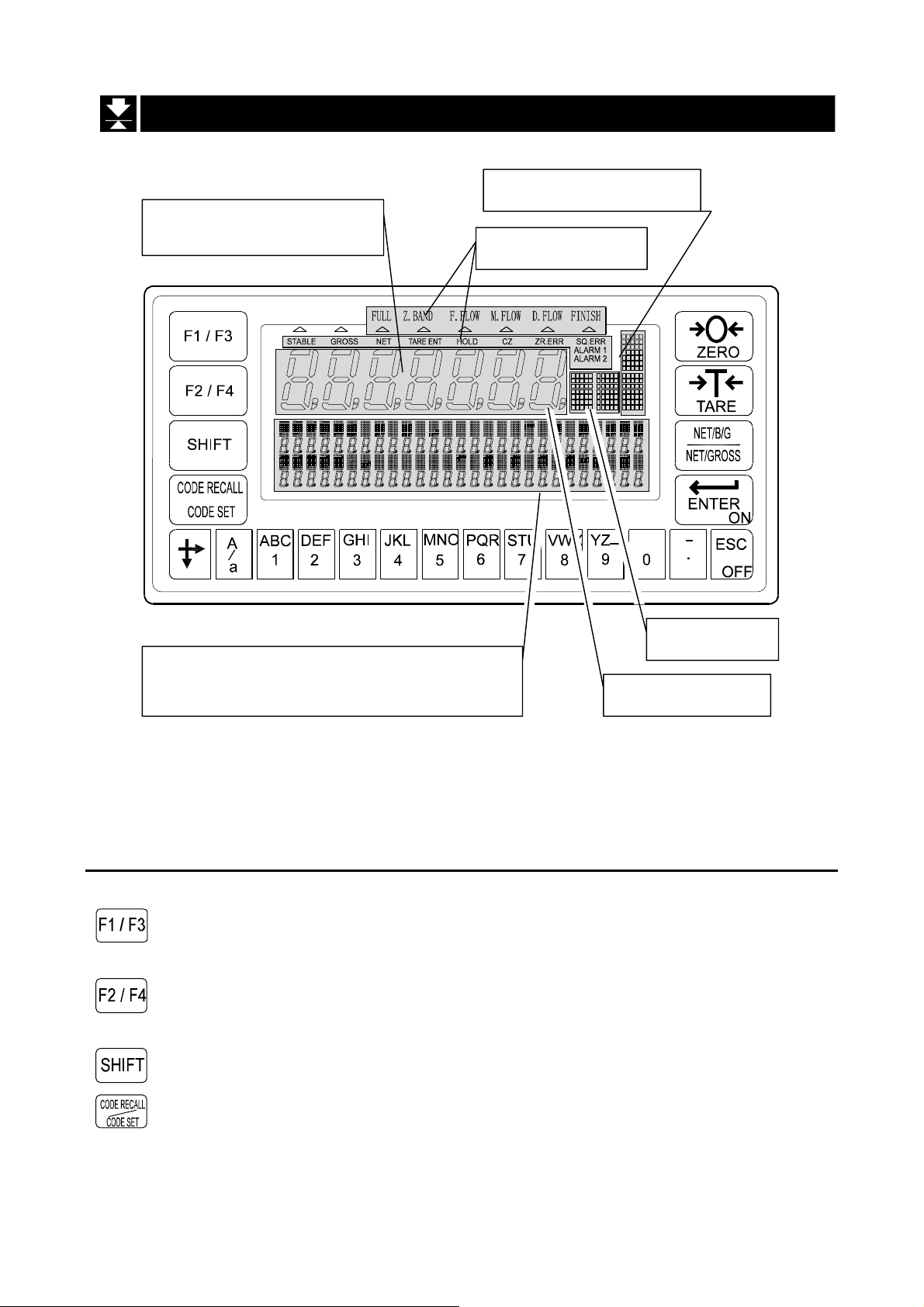
2.2. Front Panel
2.2.2.2.
Main display
Weighing data is displayed.
Front Panel
Front PanelFront Panel
Graphic status indicato
Status indicator
Sub-display
Materials, Accumulation data, parameters
and operation guidance are displayed.
2.2.1.
2.2.1. Keys
2.2.1.2.2.1.
Keys
KeysKeys
Unit indicato
Standby indicato
Pressing this key, the key works as the F1 key.
Pressing the SHIFT key and this key, the key works as t he F3 key.
Pressing this key, the key works as the F2 key.
Pressing the SHIFT key and this key, the key works as t he F4 key.
The key to select a function of the key.
The key to open the material code or recipe code.
Pressing the SHIFT key and this key, the key works as the m ater ial
code edit key.
Pressing the ENTER key and this key, the key works as the recipe
code edit key.
AD-4402 Page 7
Page 10
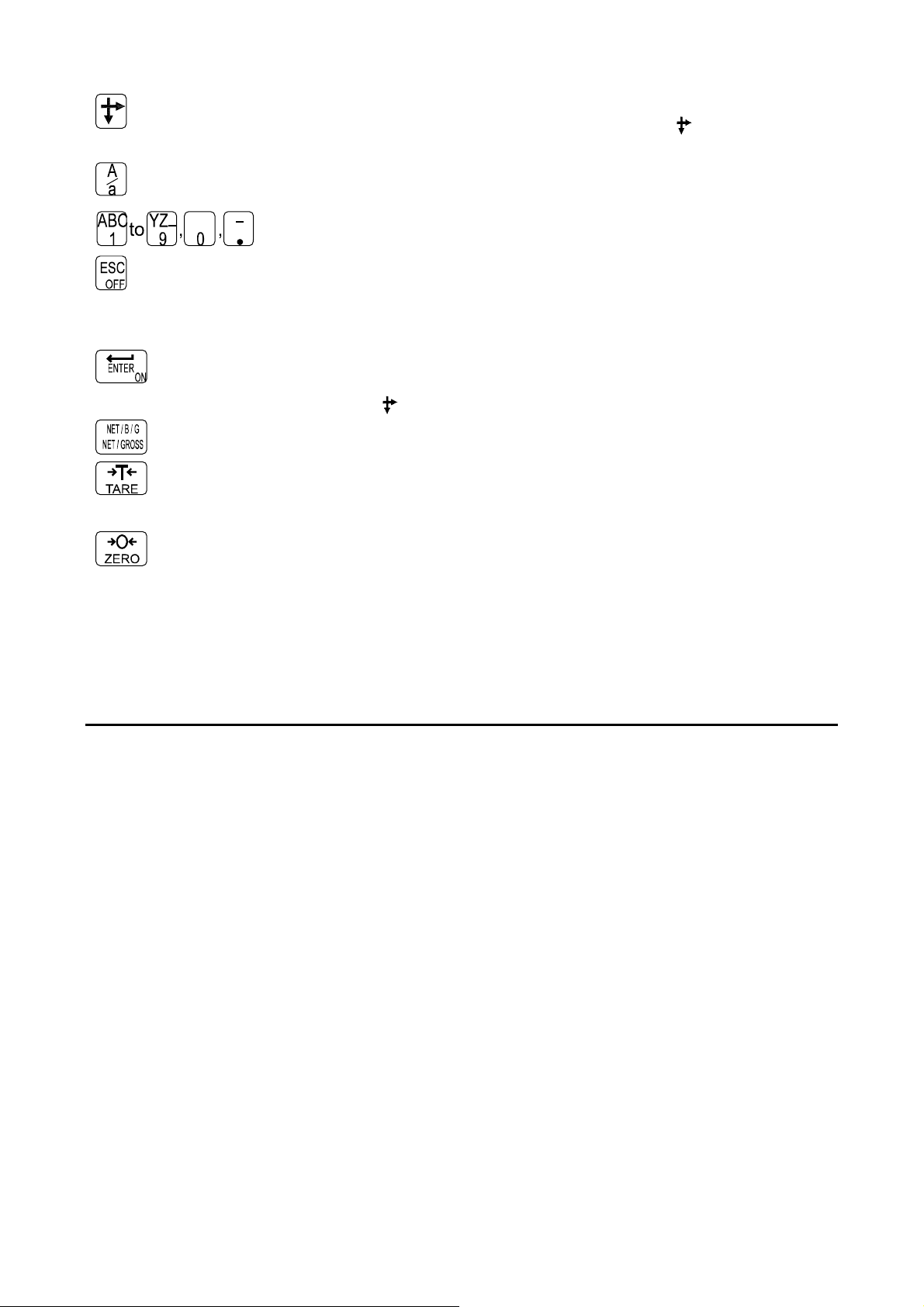
The key to move the cursor or scroll the function number.
Press and hold the SHIFT key and press the key is used to
decrease the code number.
The key to select alphabetical keys, upper keys, lower keys or
numerical keys.
Alphanumeric keys.
The escape key. Pressing and holdi ng the key ab ove three seconds
in normal weighing mode, the display is turned off (standby mode).
The ESC key is used to undo the last key and to return to the last
mode.
The ENTER key for parameter settings.
The key to be turned on the display.
Pressing the
The key to select net or gross
The tare key. The key is displayed the net value that subtracts tare
weight from a current weighing.
The zero key to zero current weighing display.
key and this key, the key works as the menu key.
2.2.2.
2.2.2. Symbols
2.2.2.2.2.2.
Main display Gross or net is displayed.
Sub display Code numbers, operation guidance, graph, comparison parameter
Unit indicator The indicator is displayed that the weighing unit is selected in the
Status indicator The current weighing status is displayed.
Graphic status
indicator
STABLE Lighting the sign, the current weighing display is stable.
Symbols
SymbolsSymbols
and other are displayed selectiv el y.
calibration mode. Refer to section "5. Calibra tion".
The classification number is displayed, when occurred an error or
informed an alarm.
The current weighing situation is displayed with symbols.
GROSS Displaying the gross data in the main display, the sign is lighted.
Page 8 AD-4402
Page 11

NET Displaying the net data in the main display, the sign is lighted.
TARE ENT Tare entered.
Storing the net value, the sign is lighted.
HOLD Fixing the main display, the sign is lighted.
CZ Center of zero.
When the gross weigh t is in t h e ce nt er of t he zero p oin t, th e s ign is
lighted.
ZR.ERR Zero error.
Error message for zero ing the gross data of the main display.
SQ.ERR The sequence error sign.
A message for weighing sequence error.
ALARM 1 An error sign for over load or emergency stop mode.
ALARM 2 A fatal error sign. Example: The wire form loadcell is broken.
Standby indicator In the standby mod e, al l inter faces ar e turn ed off an d int ernal circ uit
works only.
FULL
Z. BAND
When the gross data exceeds the full limit, the sign is lighted.
The zero band sign.
When the gross data is within the ran ge of the ze ro band (arou nd
the zero point), the sign is lighted.
F.FLOW
M.FLOW
D.FLOW
FINISH
The full flow g a t e sign.
The medium flow gate sign.
The dribble flow gate sign.
The finish sign.
AD-4402 Page 9
Page 12
2.3.
,
A
A
A
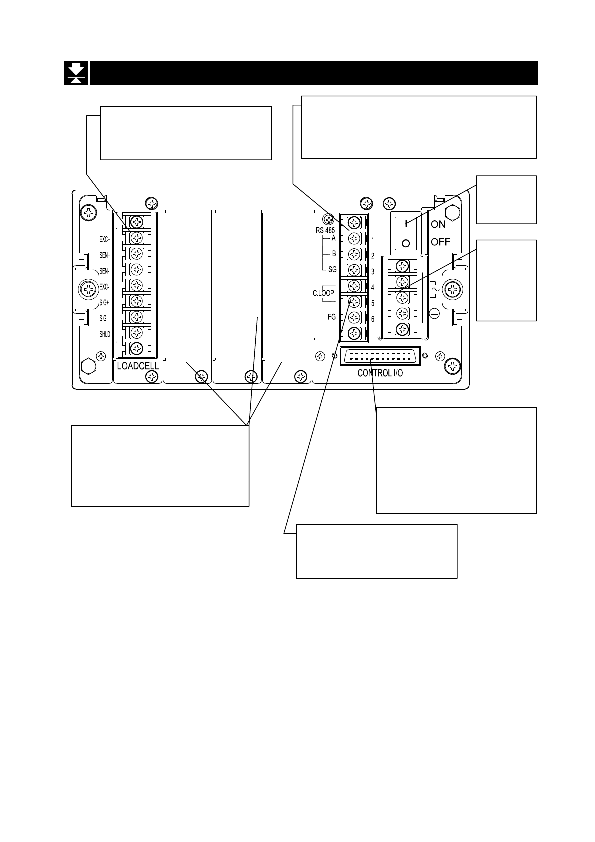
2.3. Rear Panel
2.3.2.3.
Loadcell terminal.
Eight pieces of 350Ω loadcell
can connect in parallel.
Rear Panel
Rear PanelRear Panel
Built-in RS-485 terminal.
The possibility: to read weighing data,
write parameters, connect 32 units of the
indicator with the multi-drop connection
Main
power
switch
Power
cord
terminal
C85V
~ 250V
Option slot to connect
maximum three options.
Example: BCD output, Relay
output, Analog output and field
bus.
Control I/O to connect to
external control units.
11 input terminals,
11 output terminals,
n input comm on terminal
n output common term inal
Built-in current loop output
Use to connect A&D
external monitor
Page 10 AD-4402
Page 13
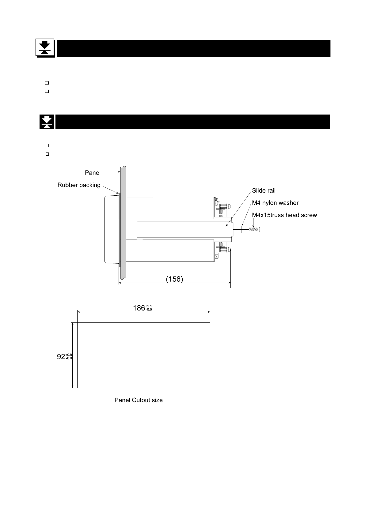
Caution
Remove the power cord before installing the indicator and other.
Build in the option before installing the indicator.
The indicator can mount on the panel using the slide rail.
If the accessory packing rubber is used, the front panel is equivalent to IP-65 of IEC 529.
3.
3. Installation
3.3.
3.1.
3.1. Mounting Indicator
3.1.3.1.
Installation
InstallationInstallation
Mounting Indicator
Mounting IndicatorMounting Indicator
AD-4402 Page 11
Page 14
Caution
Share the loadcell cable from noise-generating device and these power lines
beacuse loadcell signal is sensitive.
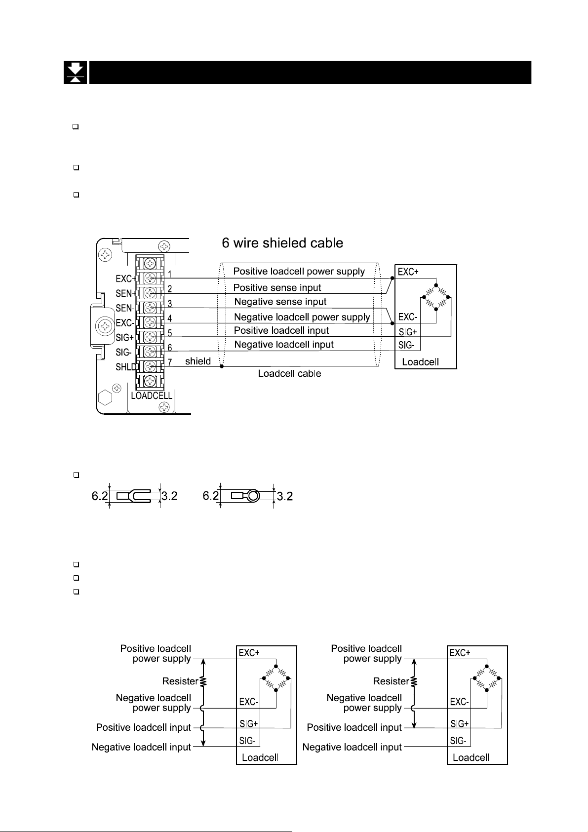
We recommend you to use the 6 wire shielded cable to prevent loss of weighing
precision.
The loadcell cable l eng th i s shor ter than 5 m, y ou may be use a 4 w ir e shi elded c abl e
with terminals 1 & 2 shorted (EXC+ & SEN+ shorted) and terminals 3 & 4 shorted
(EXC- & SEN- shorted ).
3.2.
3.2. Connecting Loadcell Cable
3.2.3.2.
Connecting Loadcell Cable
Connecting Loadcell CableConnecting Loadcell Cable
Adaptable Compression Terminal Parts
Use the adaptable compression terminal parts to the cables
Loadcell Output Adjustment for Zero Calibration (Zero Point)
When a message "CERR2" is displayed, zero point of zero ca libration is too large.
When a message "CERR3" is displayed, zero point of zero calibration is too small.
Use the resist er more than 50 kΩ with low (good) temperature coefficient, when
adding a resister to adjust the loadcell output to indicator terminals.
In Case of Too Lage Output In Case of Too Small Output
Page 12 AD-4402
Page 15
3.2.1.
3.2.1. Verifying
3.2.1.3.2.1.
Verifying Loadcell Output and Input Sensitivity
VerifyingVerifying
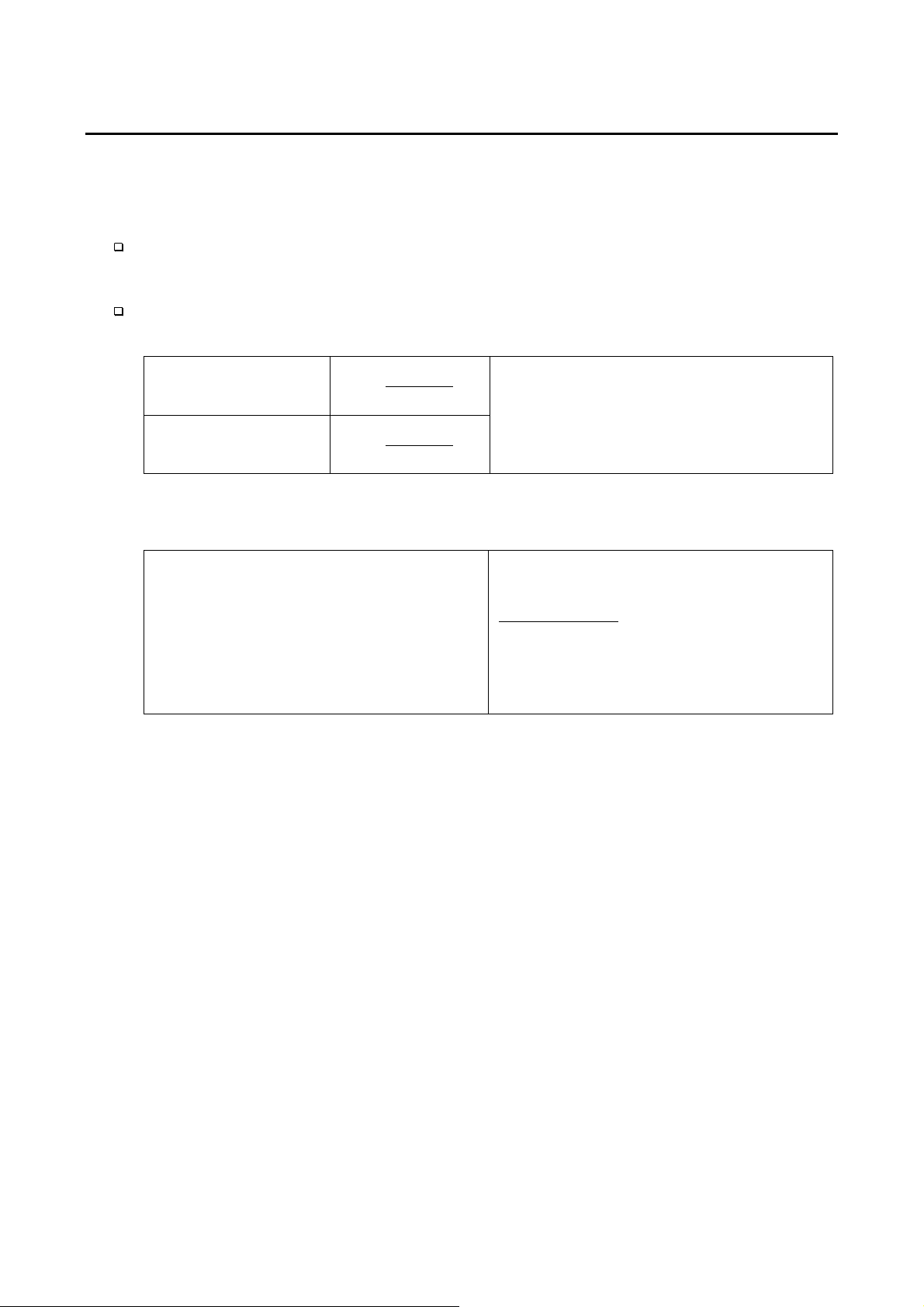
The input sensitivity of the indicator is 0.3µV/division or more. Adapt to the following
inequality, w hen you desig n a weighing instrume nt using the indicator a nd loadc ell(s).
Caution
A change in input voltage sensitivity is equiva lent to a one division change of
the display. Select as large an input voltage sensitivity voltage as possible so
that the weighing interval becomes stable.
Consider the leverage if a lever is used.
Loadcell Output and Input Sensitivity
Loadcell Output and Input Sensitivity Loadcell Output and Input Sensitivity
Weighing instrument
using one loadcell.
Weighing instrument
using multi-loadcell
Verification Example
Verification Example
Verification ExampleVerification Example
Design:
Loadcell N=1
Rated capacity A=750 [kg]
Rated output B=3 [mV/V]
Excitation voltage E=5000 [mV]
Weighing interval D=0.05 [kg]
Weighing capacity 300 [kg]
3.0∗∗≤
3.0
DBE
A
∗∗
≤
DBE
∗
NA
A:Rated capacity of loadcell [kg]
B:Rated output [mV/V]
D:Weighing interval [kg]
E:Excitation voltage [mV]
N:Number of loadcells
05.035000≥=∗∗
750
regard the in strument as a good design.
3.01
. Therefore,
AD-4402 Page 13
Page 16
Caution
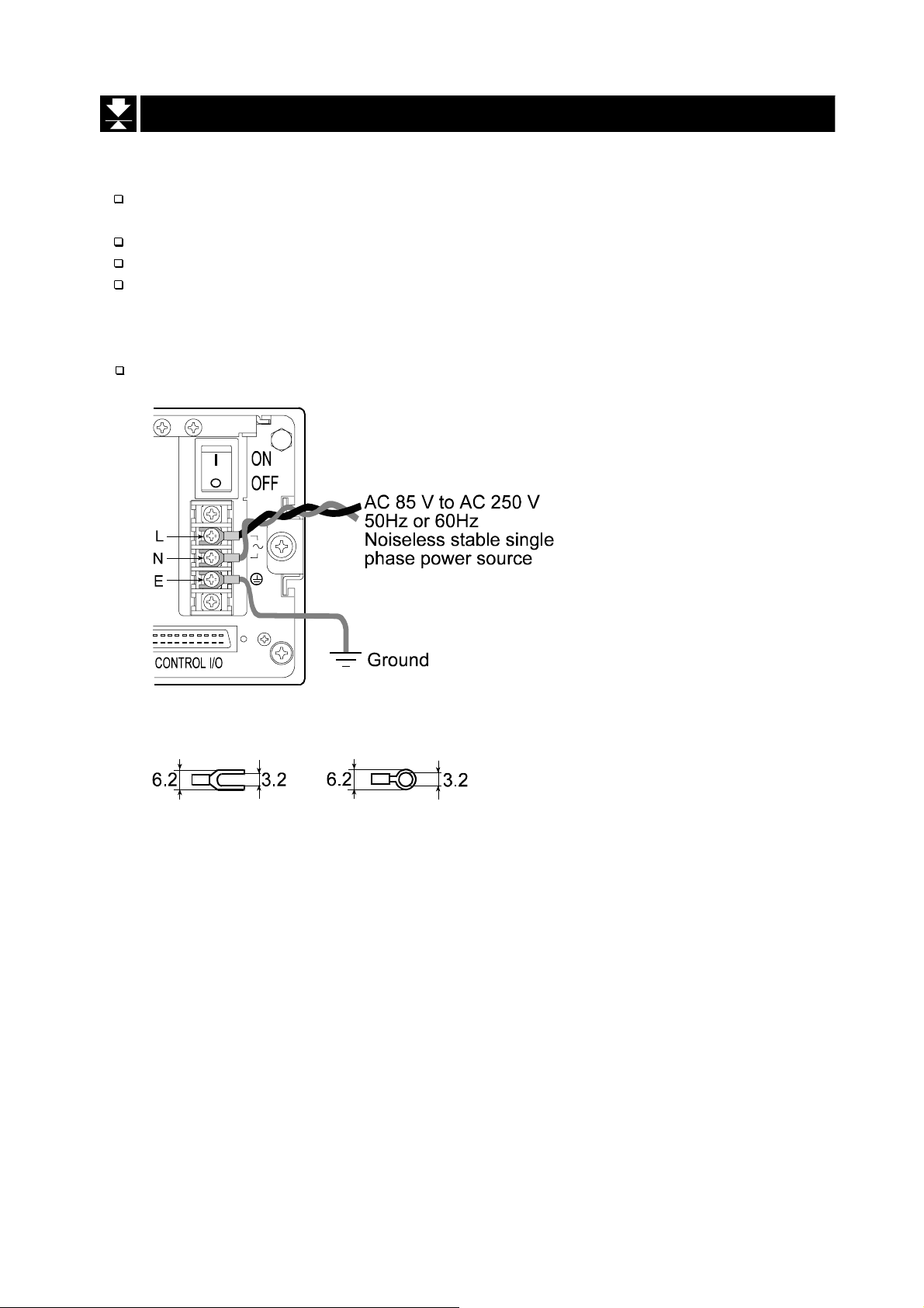
Gorund the indicator with terminal E to avoid receiving an electric shock and
an error due to discharge a static electricity.
Share the ground wire from electrical device that generats noise .
Do not use unstable power source.
Share the power cord form the moter system (as noise-generating device) to
avoid operation error.
The power source can use AC 85V to AC 250V with 50 Hz or 60 Hz.
3.3.
3.3. Wiring Power Cord
3.3.3.3.
Wiring Power Cord
Wiring Power CordWiring Power Cord
Adaptable Compression Terminal Parts
Page 14 AD-4402
Page 17
Caution
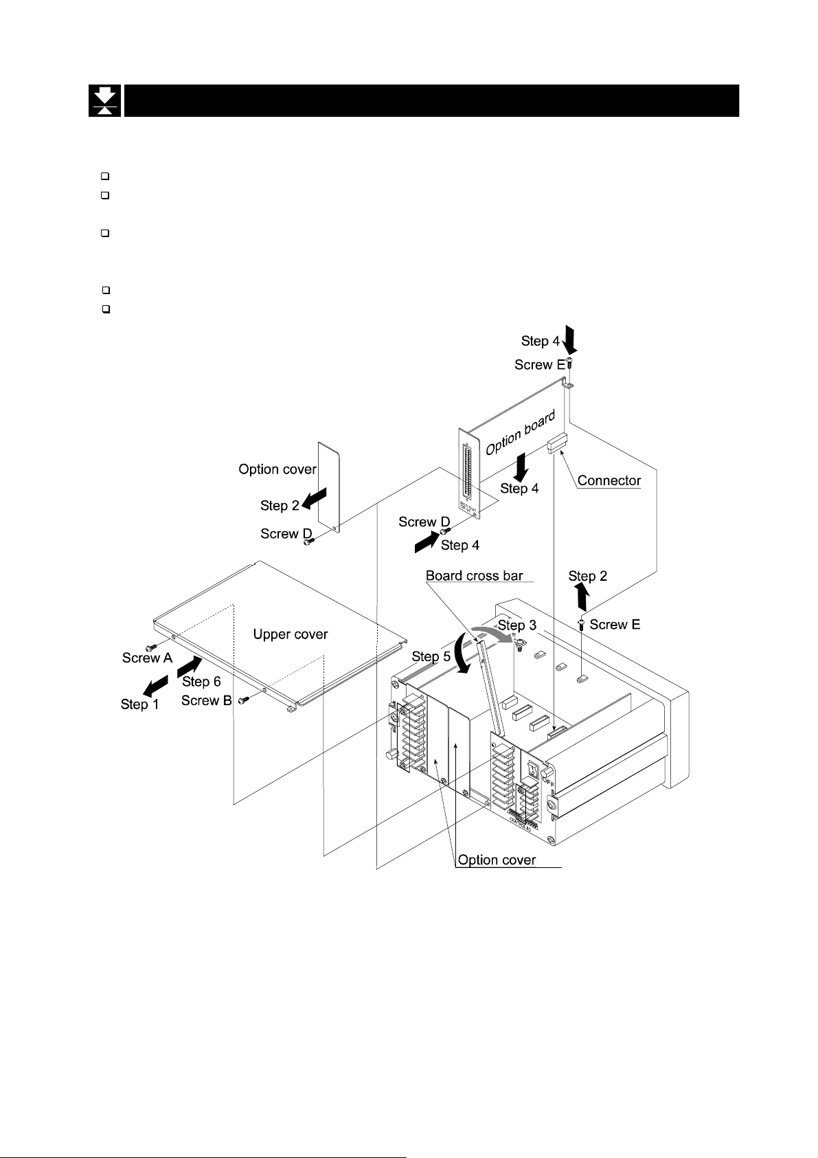
Remove the power cord before operation to install the option.
Do not touch an inside parts within ten seconds after removing the power cord
because you may receive an electric shock.
Do not forget to tighten the screw. If the screw is not tightened, it may cause
short circuit or an error due to noise.
Three option boards can install in the slots.
Initialize the RAM data in accordance with section 9.4. Initializing Parameters.
3.4.
3.4. Installing Options
3.4.3.4.
Installing Options
Installing OptionsInstalling Options
AD-4402 Page 15
Page 18
4.
4. Basic Operation
4.4.
4.1.
4.1. Key Operation Examples
4.1.4.1.
This section is described the way of key operation.
4.1.1.
4.1.1. Standby Mode
4.1.1.4.1.1.
OFF Press and hold the OFF key above three seconds in the
ON The ON key is used to turn on the indicator.
4.1.2.
4.1.2. Cursor
4.1.2.4.1.2.
Basic Operation
Basic OperationBasic Operation
Key Operation Examples
Key Operation ExamplesKey Operation Examples
Standby Mode
Standby ModeStandby Mode
weighing mode. Then the indicator enters the standby mode
and displays standby indicator.
In the standby mode, All interface is turned off and internal
circuit works only.
Cursor Operation
CursorCursor
Operation
Operation Operation
There is the cursor on a segment (an item) that is turned on and off.
The key is used to move the cursor forward.
SHIFT + Press and hold the SHIFT key and press the key is used to
move the cursor backward.
ENTER The ENTER key is used to enter the selected item.
ESC The ESC k ey is used to re turn to t he las t mode and t o und o the
last key operation.
4.1.3.
4.1.3. Inputting
4.1.3.4.1.3.
The character can be input in a current segment (an item) in adaptable mode.
A/a The A/a key is used to change numerical key, upper keys, lower
Alphanumerical The alphanumerical keys and the ENTER key is used to enter
ENTER The ENTER key is used to specify the alphanumerical data.
ESC The ESC key is used to undo the last key operation and to
Inputting Characters
InputtingInputting
Characters
Characters Characters
keys and alphabetical key.
the parameters and to select a code number directly.
return to the last mode.
Page 16 AD-4402
Page 19

4.1.4.
4.1.4. The Way of Calling a Code
4.1.4.4.1.4.
The Way of Calling a Code
The Way of Calling a CodeThe Way of Calling a Code
In Case of a Material Code:
Step 1 Suppose that is set the function parameter [5qf- 8] to [0] .
Step 2 Press the CODE RECALL key in weighing mode.
Step 3 Set the number of a material code with the following keys:
The key is used to increase the code number.
SHIFT + Press and hold the SHIFT key and press the key is used to
decrease the code number.
Numerical The numerical keys and the ENTER key is used to select a
code number directly and to enter the parameters.
ENTER The ENTER key is used to specify the number.
ESC The ESC key is used to undo the last key and to return to the
last mode.
In Case of a Recipe Code:
Step 1 Suppose that is set the function parameter [5qf- 8] to [1] or [2].
Step 2 Press the CODE RECALL key in weighing mode.
Step 3 Set the number of a recipe code with the following keys:
, SHIFT + , Numerical, ENTER, ESC keys
4.1.5.
4.1.5. The Way of Entering a Correction Mode
4.1.5.4.1.5.
The Way of Entering a Correction Mode
The Way of Entering a Correction ModeThe Way of Entering a Correction Mode
In Case of a Material Code:
Step 1 Press and hold the SHIFT key and press the CODE RECALL key in weighing mode.
Step 2 Select a number of a material code using the following keys:
, SHIFT + , Numerical, ENTER, ESC keys
Step 3 Edit some items of a material code using numerical keys and the ENTER key.
Step 4 Press the ESC key to return to weighing mode.
In Case of a Recipe Code:
Step 1 Press and hold the ENTER key and press the CODE RECALL key in weighing mode.
Step 2 Select a number of a recipe code using the following keys:
, SHIFT + , Alphanumerical, A/a, ENTER, ESC keys
Step 3 Edit some items of a recipe code using alphanumeric keys and the ENTER key.
Step 4 Press the ESC key to return to weighing mode.
AD-4402 Page 17
Page 20

4.1.6.
4.1.6. The Way of Entering Menu
4.1.6.4.1.6.
Step 1 Press and hold the ENTER key and press the key in weighing mode.
Then the first layer of menu is display.
Step 2 Use the following keys in the menu :
Step 3 Press the ESC key to return to weighing mode several times.
The Way of Entering Menu
The Way of Entering MenuThe Way of Entering Menu
, SHIFT, Alphanumerical, A/a , ENTER, ESC keys
Page 18 AD-4402
Page 21
4.2.
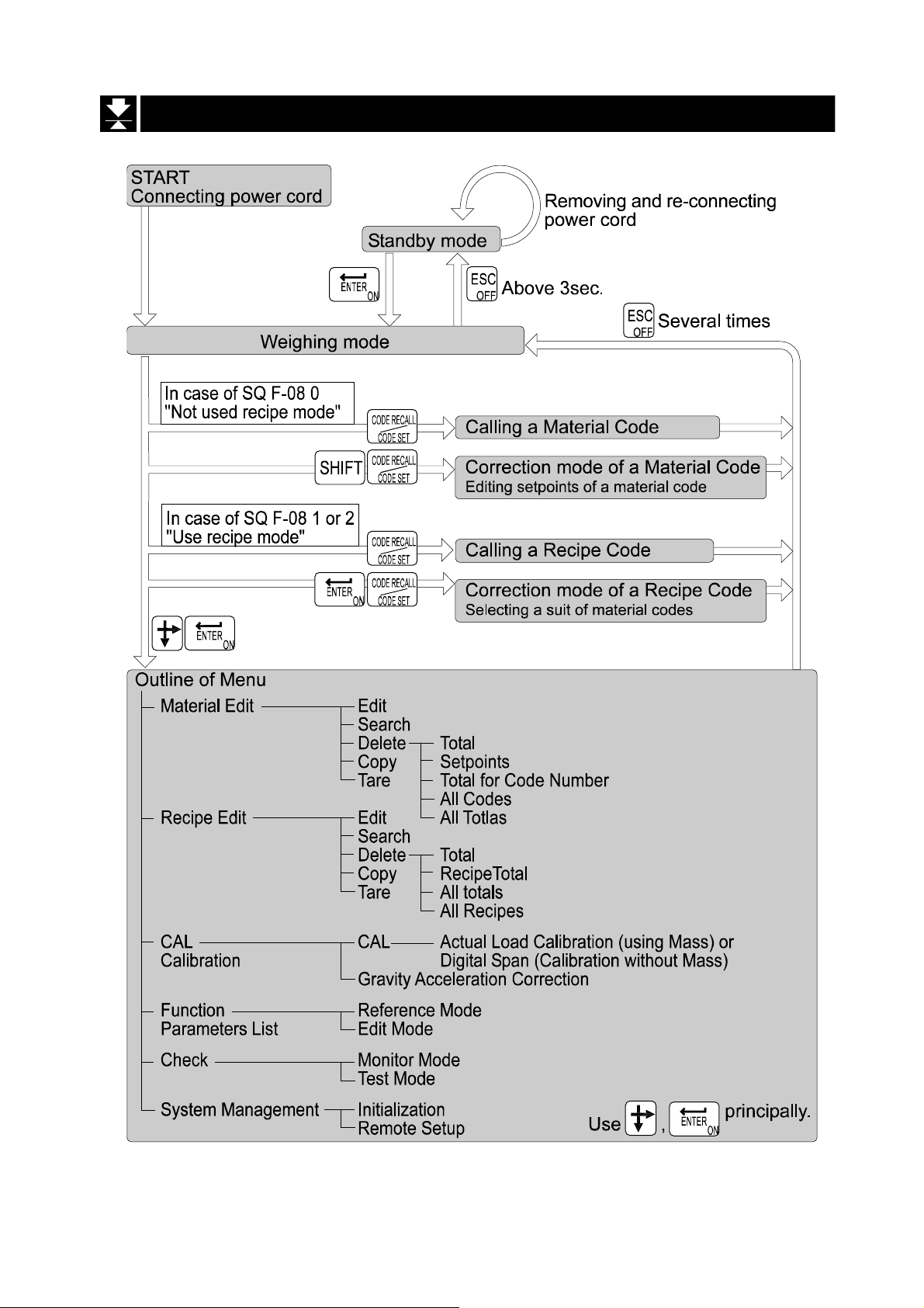
4.2. Status Chart (Mode map
4.2.4.2.
Status Chart (Mode map))))
Status Chart (Mode mapStatus Chart (Mode map
AD-4402 Page 19
Page 22

5.
5. Calibration
5.5.
The indicator, which is connected loadcell unit, can weigh the "weight" value on the
loadcell pan and display its "mass" value. The calibration function is used to adjust
the weighing value (displaying value) so that the weighing system can weigh
correctly.
There are two way of the calibration. The "actual load calibration" uses a rated
mass and zero output from the loadcell. The "digital span" inputs arbitrary values
(calculated by hand). T hese methods are selected in the calibration procedure.
There is a compensation function of the "gravity acceleration correction".
This function is used, when a calibrated weighing system is moved to other place.
These calibration para meters are stored in the indicator without any power supply.
Calibration
CalibrationCalibration
Common Calibration Items
Unit The "g", "kg" and "t" or "lb" can be selected.
Decimal point The decimal point can be selected form "not used" to "four
decimal places".
Minimum division The minimum division of the weighing display.
Weighing capacity The maximum display of the weighing display.
Items for the "Actual Load Calibration"
Common items Unit, decimal point, minimum di vi sion and w eighing capacity
Zero point adjustment A zero point output is used from the loadcell unit.
Span adjustment Rated mass is place on the weighing pan and is weighed.
The sensitivity is adjusted. This sensitivity is the same as "
sensitivity " of digital span.
Items for "Digital Span"
Common items Unit, decimal point, minimum di vi sion and w eighing capacity
Zero point output The numerical data is input as zero point output of loadcell
unit.
Rated capacity The rated capacity of the loadcell is input.
The sensitivity of the loadcell is input.
Caution
When the CAL switch on the A/D board is "DISABLE", any calibration can not
perform.
Do not perform any calibration during a weighing sequnce operation.
Entering calibration mode during a weighing sequnce operation, the weighing
sequnce operation is terminated. Calibrate the weighing system, when a
weighing sequnce operation does not work
The accuracy of the "Digital Span (Calibration without Mass)" is 1/1000.
Do not use a "loadcell summing box", the "digital span" is performed.
It is necessary that the loadcell sensitivity is exactly known, if the "digital
span" is used.
Page 20 AD-4402
Page 23

5.1.
5.1. Actual Load Calibration (using Mass)
5.1.5.1.
ESC key If you want to return to the weighing mode during the
ENTER key When the key is pressed, the procedure stores a current
Step 1 Press and hold the ENTER key and press the key to display the
menu in a weighing mode.
Step 2 Press the key twice to select the menu CAL.
Press the ENTER key to enter the calibration mode.
Step 3 Press the ENTER key to enter the menu CAL.
Step 4 Select a unit using the num erical keys and press the ENTER key
to store it.
Step 5 Select a decimal point using the numerical keys and press the
ENTER key to store it.
Actual Load Calibration (using Mass)
Actual Load Calibration (using Mass)Actual Load Calibration (using Mass)
calibration mode, press the ESC key anytime. And it has
effect until the last displayed parameter.
Example: zero adjustment only, etc.
parameter and proceeds to next step.
Step 6 Select a minimum division using the numer ical keys and press the
ENTER key to store it.
Step 7 Select a weighing capcity usi ng the n um eri cal key s and press the
ENTER key to store it.
Step 8 Perform the zero point adjustment.
Place nothing on the weighing pan and press the ENTER key to
store it after the STABLE indicator is displayed.
Whether the STABLE indicator is displayed or not, if you want to
store it, wait for ten seconds and press the ENTER key.
Step 9 Specify a total mass value to place on the weig hing pan using the
numerical keys and press the ENTER key to store it.
Step10 Place the specifyed mass on the weighing pan and press the
ENTER key to store it after the STABLE indicator is displayed.
Whether the STABLE indicator is displayed or not, if you want to
store it, wait for ten seconds and press the ENTER key.
Step11 Press the ESC key to return the weighing mode.
AD-4402 Page 21
Page 24

5.2.
5.2. Digital Span (Calibration without Mass)
5.2.5.2.
ESC key If you want to return to the weighing mode during the
ENTER key When the key is pressed, the procedure stores a current
Step 1 Press and hold the ENTER key and press the key to display the
menu in a weighing mode.
Step 2 Press the key twice to select the menu CAL.
Press the ENTER key to enter the calibration mode.
Step 3 Press the ENTER key to enter the menu CAL.
Step 4 Select a unit using the num erical keys and press the ENTER key
to store it.
Step 5 Select a decimal point using the numerical keys and press the
ENTER key to store it.
Digital Span (Calibration without Mass)
Digital Span (Calibration without Mass)Digital Span (Calibration without Mass)
calibration mode, press the ESC key anytime. And it has
effect until the last displayed parameter.
Example: zero adjustment only, etc.
parameter and proceeds to next step.
Step 6 Select a minimum division using the numer ical keys and press the
ENTER key to store it.
Step 7 Select a weighing capcity usi ng the n um eri cal key s and press the
ENTER key to store it.
Step 8 Press the F1 key to proceed to the digital span procedure.
Step 9 Input the zero point value usi ng the nu mer i cal keys and press the
ENTER key to store it.
Step10 Input the rated capacity of a lo adcell using the nu merical key s and
press the ENTER key to store it.
Step11 Input the sensitivity of the loadcell in the unit of mV/V using the
numerical keys and press the ENTER key to store it.
Step12 Press the ESC key to return the weighing mode.
Advise The digital span can be used for trimming of the actual l oad calibration using mass.
Page 22 AD-4402
Page 25
5.3.
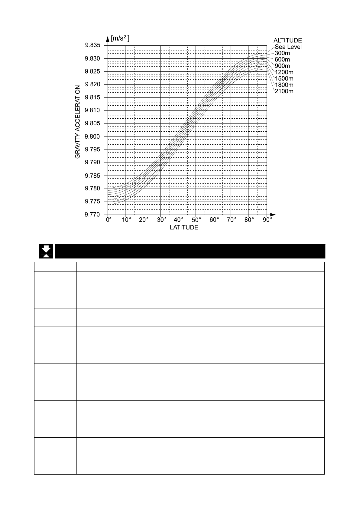
5.3. Gravity Acceleration Correction
5.3.5.3.
Gravity Acceleration Correction
Gravity Acceleration CorrectionGravity Acceleration Correction
The function compensates the weighing error due to the difference of gravity acceleration.
G1 The place where the weighing system is calibrated.
G2 The place where the weighing system is used.
ESC key If you want to return to the weighing mode during the
calibration mode, press the ESC key anytime.
ENTER key When the key is pressed, the procedure stores a current
parameter and proceeds to next step.
Step 1 Press and hold the ENTER key and press the key to display the menu in a
weighing mode.
Step 2 Press the key twice to select the menu CAL. Press the ENTER key to enter the
calibration mode.
Step 3 Select the menu G with the key. Press the ENTER key to enter it.
Step 4 Input the gravity acceleration at G1 using the num erical keys and press the
ENTER key to store it.
Step 4 Input the gravity acceleration at G2 using the num erical keys and press the
ENTER key to store it.
Step 5 Press the ESC key to return the weighing mode.
5.3.1.
5.3.1. Gravity Acceleration Reference
5.3.1.5.3.1.
Amsterdam 9.813 m/s2Manila 9.784 m/s
Athens 9.800 m/s2Melbourne 9.800 m/s
Auckland NZ 9.799 m/s2Mexico City 9.779 m/s
Bangkok 9.783 m/s2Milan 9.806 m/s
Birmingham 9.813 m/s2New York 9.802 m/s
Brussels 9.811 m/s2Oslo 9.819 m/s
Buenos Aires 9.797 m/s2Ottawa 9.806 m/s
Calcutta 9.788 m/s2Paris 9.809 m/s
Chicago 9.803 m/s2Rio de Janeiro 9.788 m/s
Copenhagen 9.815 m/s2Rome 9.803 m/s
Cyprus 9.797 m/s2San Francisco 9.800 m/s
Djakarta 9.781 m/s2Singapore 9.781 m/s
Frankfurt 9.810 m/s2Stockholm 9.818 m/s
Glasgow 9.816 m/s2Sydney 9.797 m/s
Havana 9.788 m/s2Tainan 9.788 m/s
Helsinki 9.819 m/s2Taipei 9.790 m/s
Kuwait 9.793 m/s2Tokyo 9.798 m/s
Lisbon 9.801 m/s2Vancouver, BC 9.809 m/s
London (Greenwich) 9.812 m/s2Washington DC 9.801 m/s
Los Angeles 9.796 m/s2Wellington NZ 9.803 m/s
Madrid 9.800 m/s2Zurich 9.807 m/s
Gravity Acceleration Reference
Gravity Acceleration ReferenceGravity Acceleration Reference
2
2
2
2
2
2
2
2
2
2
2
2
2
2
2
2
2
2
2
2
2
AD-4402 Page 23
Page 26
5.4.
5.4. Calibration Error
5.4.5.4.
Error Code Treatment and Situation
CERR1
CERR2
CERR3
CERR4
CERR5
CERR6
CERR7
CERR8
CERR9
CERR10
CERR11
Calibration Error
Calibration ErrorCalibration Error
Resolution (Weighing ca paci ty / minimum division) is exceeds th e l i mita ti on.
Increase minimum division or decrease weighing capacity.
The initial load (no load output) is larger than 2mV/V.
Confirm the loadcell cable.
Negative loadcell output value. Check wiring.
Confirm the loadcell cable.
Mass value exceeds the we ighing capacity.
Use a mass within the weighing capacity. (Decrease mass value)
Mass value is too light for the calibration.
Increase mass value.
The loadcell output to be equivalent to minimum division is too small.
Use more rough minimum division.
The polarity of loadcell output is inversed.
Confirm the loadcell cable.
The mass value of the weighing capacity exceeds 3.2 mV/V.
Confirm the mass and weighing capacity.
Gravity acceleration is out of range.
Correct the value within the range of 9.770 ~ 9.835 m/s
Zero output of loadcell unit is out of range.
Trim the zero output within 0.0 ~ 2.0 mV/V.
The loadcell output to be equivalent to minimum division is out of range.
Trim the output within 0.0 ~ 3.2 mV/V.
2
.
Page 24 AD-4402
Page 27
6.
6. Applications
6.6.
6.1.
6.1. Hopper Scale with Material Code
6.1.6.1.
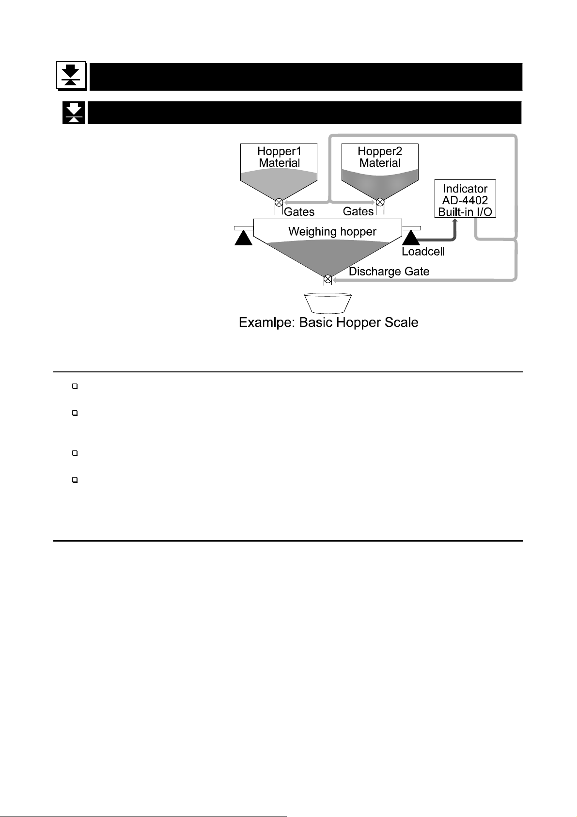
In the section, ap plicatio ns
are explained according to
the right hopper scale that
performs batch weighing
using a material code.
An application is explained
mixture of materials using
a recipe code.
The foundation of hopper
scale design is explained.
6.1.1.
6.1.1. Definition of Material Code
6.1.1.6.1.1.
Applications
ApplicationsApplications
Hopper Scale with Material Code
Hopper Scale with Material CodeHopper Scale with Material Code
Definition of Material Code
Definition of Material CodeDefinition of Material Code
The material code is necessary to store the details before use.
And the code is called with code number in a weighing.
The material code is used in the procedure that performs batch weighing or loss-in
weigh. As the result of t he procedure , a constant w eig ht of the materi al, is cal led "full "
or "full filling", can be got.
The material code consists of some index number (name) and some comparison
values to get a constant weight of the material.
The AD-4402 can store a hundred kinds of material codes.
6.1.2.
6.1.2. Recalling
6.1.2.6.1.2.
The following steps are the explanation to recall the material code stored in the
indicator. Suppose that the recipe code is not used. (The menu
setting] - [Sequence] - [Basic] - [Recipe mode]
Caution
The material code can be recalled during the last weighing. But the code
effects after the batch finish (after finishing the last weighing).
Step 1 Press the CODE RECALL key.
Recalling MMMMaterial
RecallingRecalling
aterial CCCCode
aterial aterial
ode
odeode
is set to [5q f- 8] [0] )
[Function] - [Function
Then the material code blinks.
Step 2 Enter the material code using numerical keys
The details of the material code are displayed in the sub-display.
Step 3 Press the ENTER key to decide the code.
AD-4402 Page 25
Page 28

6.1.3.
6.1.3. Editing Principle Parameters of Material Code
6.1.3.6.1.3.
You can edit the parameters of target weight, free fall and etc. displayed on the subdisplay during a weighing. And items of sub-display can be selected at the menu
[Function] - [Function setting] - [General] - [Sub-display].
Editing Principle Parameters of Material Code
Editing Principle Parameters of Material CodeEditing Principle Parameters of Material Code
Caution
If the flash memory is selected for memory backup (0tHf-11
sequential weighing is stopped.
Step 1 Press and hold the SHIFT key and press the CODE RECALL key.
Then the material code blinks.
Step 2 Enter the material code using numerical keys
The details of the material code are displayed in the sub-display.
Step 3 Press the ENTER key to decide the code.
Step 4 Select a parameter using the key on the sub-display.
Step 5 Enter the parameter using numerical keys and press the ENTER key to store it.
Step 6 If you continue the change, proceed step 4 and 5.
Step 7 If you want to finish the ch ange, press the ESC key to return to weighing mode
0tHf-11), a current
0tHf-110tHf-11
several times.
6.1.4.
6.1.4. Referr
6.1.4.6.1.4.
You can refer to next material code in the sequential mode that uses plural material
codes. Suppose that the recipe code is not used. (The menu
setting] - [Sequence] - [Basic] - [Recipe mode]
Step 1 Press the CODE RECALL key.
Then principle parameters of the next material code are displayed in the sub-
display.
Step 2 Press the ESC key to return to current mode.
Referring
ReferrReferr
ing next Material Code
inging
next Material Code
next Material Code next Material Code
is set to [5q f- 8] [0])
[Function] - [Function
Page 26 AD-4402
Page 29
6.1.5.
6.1.5. Editing Full Parameters of Material Code
6.1.5.6.1.5.
Editing Full Parameters of Material Code
Editing Full Parameters of Material CodeEditing Full Parameters of Material Code
A material code consists of the following parameters.
Name
Material Code
Material name
Material Hopper No.
Final
Free Fall
Preliminary
Optional Preliminary
Over
Under
Zero Band
Full
Tare
Supplementary Flow Open Timer
Supplementary Flow Close Timer
Automatic Free Fall Range
Initial Dribble Flow
Initial Medium Flow
Total Weight
Total Counts
Display Name Display
Symbol
Code
Mat Name grain
Mat Hopper Hopper 1
Final Final 10.00 kg
Free Fall FFall 0.01 kg
Preliminary Plm 1.00 kg
OP.Preliminary OPPlm 2.00 kg
Over Over 0.10 kg
Undr Undr 0.10 kg
Zero Band 0Band 0.02 kg
Full Full 0.05 kg
Tare Tare 5.00 kg
SF open timer SFOT 0.00 s
SF close SFCT 0.00 s
AFFC range AFFC 0.00 kg
Initial DF IDF 0.00 kg
Initial MF IMF 0.00 kg
Tot Tot 10.00 kg
Tot# Tot# 1
Code
Display
Example
11
Memory
Backed up
RAM
( factory
setting)
or
flash
memory
Backed up
RAM
These parameters are stored in backup memory without power supply.
Refer to the backup method [0tHf-11] of the function list.
Caution
If the flash memory is selected for memory backup [0tHf-11
sequential weighing is stopped.
0tHf-11], a current
0tHf-110tHf-11
Edit Material Code
Step 1 Press and hold the ENTER key and press the key.
Then menu MatEdit blinks.
Step 2 Press the ENTER key to enter the material code edit. Then menu Edit blinks.
Step 3 Press the ENTER key to enter menu edit.
Step 4 Select the material code using numerical keys and press the ENTER.
Step 5 Enter the material name using alpanumerical keys and press the ENTER key.
Step 5 Edit other parameters using numerical keys, ENTER key and key.
Step 6 If you want to finish the ch ange, press the ESC key to return to weighing mode
several times.
AD-4402 Page 27
Page 30

Search Material Code
Use this menu to search blank material code.
Step 1 Press and hold the ENTER key and press the key.
Then menu MatEdit blinks.
Step 2 Press the key to select menu Search. And press the ENTER key.
Step 3 Then the message is displayed.
Step 4 Press the ENTER key to prceed next step.
Then the result is displayed.
Step 5 Press the ESC key to return to weighing mode several times.
Delete Material Code
The parameter of the material code can be reset in the following menu.
Total value
Setpoints
Total of a material code
All material code
All total
Example of Deleting Total Value
Step 1 Press and hold the ENTER key and press the key.
Then menu MatEdit blinks.
Step 2 Press the key to select menu Delete. And press the ENTER key.
Step 3 Select menu Total using the key. And press the ENTER key.
Step 4 Enter the material code using numerical keys and press the ENTER key.
Step 5 Press the ESC key to return to weighing mode several times.
Copy Material Code
The parameters of material code are copied. This copy includes a total weight value
and times of accumulation.
Step 1 Press and hold the ENTER key and press the
Then menu
Step 2 Press the key to select menu Copy. And press the ENTER key.
Step 4 Specify a original code number using numerical keys and press the ENTER key.
Step 5 Specify a duplicated code num ber using numerical keys and press the ENTER key.
MatEdit blinks.
key.
Step 6 Press the ESC key to return to weighing mode several times.
Page 28 AD-4402
Page 31

Tare of Material Code
Use to copy current tare to the preset tare.
Set a preset tare function [gebf-12 ] of the function list.
[gebf-12] [0] If the preset tare of the code is zero, the last tare value effects.
(factory settings)
[gebf-12] [1] If the preset tare of the code is zero, tare value is reset.
Step 1 Press and hold the ENTER key and press the key.
Then menu MatEdit blinks.
Step 2 Press the key to select menu Tare. And press the ENTER key.
Step 4 Specify a code number using numerical keys and press the ENTER key.
Then current tare value is copied to preset tare.
Step 5 Press the ESC key to return to weighing mode several times.
AD-4402 Page 29
Page 32

6.2.
6.2. Simple Hopper Scale with Recipe Code
6.2.6.2.
The section explains for recipe code (another name: formal function). The recipe
code is used on a simple hopper scale to mix several materials that are preset target
value. "The simple hopper scale" means that does not control the ratio and a weight
of ingredient, but simply accumulates the preset target weight of the material code.
Therefore, the recipe code is a code to accumulate the preset target weight of the
material code.
Simple Hopper Scale with Recipe Code
Simple Hopper Scale with Recipe CodeSimple Hopper Scale with Recipe Code
6.2.1.
6.2.1. Definition of Recipe Code (
6.2.1.6.2.1.
A recipe code consists of plural preset material codes.
Maximum ten material codes can be stored in a recipe code.
A recipe code is described in order to accumulate target weight of the material code.
The indicator AD-4402 can store a hundred recipe codes.
The recipe code is necessary to store the details before use.
And the code is called with code number in a weighing.
The recipe code is a co de to accumulate th e preset target w eight of the mat erial code.
If a recipe code is used in the batch w eighing (or loss-in weight), y ou can get a weight
that is accumulated the preset target weight of the material code.
The recipe sequence that is used recipe code ca lls formula sequence, too.
Definition of Recipe Code (Formal
Definition of Recipe Code (Definition of Recipe Code (
Page 30 AD-4402
Formal Function)
FormalFormal
Function)
Function) Function)
Page 33

6.2.2.
6.2.2. Using a Recipe Code
6.2.2.6.2.2.
Using a Recipe Code
Using a Recipe CodeUsing a Recipe Code
Set the menu
sequential mode ( [5q f- 8] to [1] or [2] ), when the recipe code is used .
[5q f- 8] [1] Semi-automatic mixture sequence
[5q f- 8] [2] Automatic mixture sequence
6.2.3.
6.2.3. Construction of Recipe Code
6.2.3.6.2.3.
The indicator AD-4402 can store a hundred recipe codes.
A recipe code can store maximum ten material codes in order of accumulating them.
These parameters are stored in backup memory without power supply.
Refer to the backup method [0tHf-11] of the function list.
Construction of Recipe Code
Construction of Recipe CodeConstruction of Recipe Code
[Function] - [Function setting] - [Sequence] - [Basic] - [Recipe mode]
Caution
If the flash memory is selected for memory backup [0tHf-11
sequential weighing is stopped.
Name
Recipe code
Recipe name
Material codes of maximum ten codes.
It is stored in order to accumlate them.
Accumulated Weight for recipe code
Accumulation Counts for recipe code
Display Symbol & Example Memory
rCode
Blend coffee
Code 1
Total Weight
10.00 kg
Total Counts
10.00 kg
0tHf-11], a current
0tHf-110tHf-11
Backed up RAM
( factory setting)
flash memory
Backed up RAM
to
or
6.2.4.
6.2.4. Recalling
6.2.4.6.2.4.
The following steps are the explanation to recall the recipe code stored in the
indicator. Suppose that the r ecipe code is us ed (The men u
- [Sequence] - [Basic] - [Reci pe mode]
Recalling a Recipe Code
RecallingRecalling
a Recipe Code
a Recipe Codea Recipe Code
is set to [5q f- 8] [1] or [2]). .
Caution
The code can be recalled during the last weighing. But the code effects after
the butch finish (after finishing the last weighing).
Step 1 Press the CODE RECALL key.
Then the recipe code blin ks.
Step 2 Enter the material code using numerical keys
The details of the recipe code are displayed in the sub-display.
Step 3 Press the ENTER key to decide the code.
AD-4402 Page 31
[Function] - [Function se tting]
Page 34

6.2.5.
6.2.5. Arranging Material Code in Recipe Code
6.2.5.6.2.5.
The way of arranging material code described in a recipe code.
Step 1 Press and hold the ENTER key and press the CODE RECALL key.
Step 2 Select a recipe code number using numerical keys and press the ENTER key.
Then first material code blinks.
Step 3 Select a material code using the following keys.
key, numerical keys and SHIFT key
Step 4 Press the ENTER key to store it. T hen the next code blinks.
Step 5 Continue step 3 and 4 until the last material code is stored.
Step 6 Press the ESC key to return to weighing mode several times.
6.2.6.
6.2.6. Editing Full Parameters of Recipe Code
6.2.6.6.2.6.
All parameters of the recipe code can be edited in this menu.
Arranging Material Code in Recipe Code
Arranging Material Code in Recipe CodeArranging Material Code in Recipe Code
Editing Full Parameters of Recipe Code
Editing Full Parameters of Recipe CodeEditing Full Parameters of Recipe Code
Edit Name of Recipe Code
Step 1 Press and hold the ENTER key and press the key.
Press the key. Then menu RecipeEDIT blinks.
Step 2 Press the ENTER key to enter the recipe code edit. Then menu edit blinks.
Step 3 Press the ENTER key to enter menu edit.
Step 4 Select a recipe code using numerical keys and press the ENTER.
Step 5 Name a recipe code using alpanumerical keys and press the ENTER key.
Step 6 If you want to finish the ch ange, press the ESC key to return to weighing mode
several times.
Search of Recipe Code
Use this menu to search blank material code.
Step 1 Press and hold the ENTER key and press the key.
Press the key. Then menu RecipeEDIT blinks.
Step 2 Press the key to select menu Search. And press the ENTER key.
Step 3 Then the message is displayed.
Step 4 Press the ENTER key to prceed next step.
Then the result is displayed.
Step 5 Press the ESC key to return to weighing mode several times.
Delete of Recipe Code
The parameter of the recipe code can be reset in the following menu.
Page 32 AD-4402
Page 35

Total value
Recipe total value
All total value
All Recipes
Example of Deleting Total Value
Step 1 Press and hold the ENTER key and press the key.
Then menu RecipeEDIT blinks.
Step 2 Press the key to select menu Delete. And press the ENTER key.
Step 3 Select menu Total using the key.
And press the ENTER key.
Step 4 Enter the recipe code using numerical keys and press the ENTER key.
Step 5 Press the ESC key to return to weighing mode several times.
Copy of Recipe Code
The parameters of recipe code are copied. This copy includes a total weight value
and times of accumulation.
Set a preset tare function [ genf-12 ] of the function list.
[genf-12] [0] If the preset tare of the code is zero, the last tare value effects.
(factory settings)
[genf-12] [1] If the preset tare of the code is zero, tare value is reset.
Step 1 Press and hold the ENTER key and press the key.
Then menu RecipeEDIT blinks.
Step 2 Press the key to select menu Copy. And press the ENTER key.
Step 4 Specify a original code number using numerical keys and press the ENTER key.
Step 5 Specify a duplicated code num ber using numerical keys and press the ENTER key.
Step 6 Press the ESC key to return to weighing mode several times.
AD-4402 Page 33
Page 36

6.3.
6.3. System Design of Hopper Scale
6.3.6.3.
6.3.1.
6.3.1. Operation and I/O Design
6.3.1.6.3.1.
In General, looking an old type hopper scale design, the simplest indicator only displayed
weighing value, other system devices communicated the control signal with each I/O
interface. And the key operation and monitoring the system separately were controlled.
The indicator AD-4402 has the I/O interface to control the system, sub-display to
monitor system infor mation, mai n display to display w eighing data and keys to c ontrol
the system in a unit.
The indicator is designed so as to be able to select arbitrary keys and terminals to
control the system form front pan el keys and th e I/O interface w ith the men u function.
And the function of keys and terminals can be designed in the same way.
The system information of sub-display can select at the function list.
6.3.2.
6.3.2. Design
6.3.2.6.3.2.
Suppose that the I/O, keys and sub-display are as follows:
Supply start: F1 key, [0thf- 2] [6]
Emergency stop key: F2 key, [0thf- 3] [13]
Dribble signal (low power): terminal B1, [0utf- 1] [6]
Batch finish signal (low power): terminal B2, [0utf- 2] [14]
Not used recipe code at "
Use default setting about sub-display [5ub f 1] [0]
System Design of Hopper Scale
System Design of Hopper ScaleSystem Design of Hopper Scale
Operation and I/O Design
Operation and I/O DesignOperation and I/O Design
Design Example
DesignDesign
Example
Example Example
Not used recipe sequence
"[5q f- 8] [0]
Setup
Step 1 Enter the function list.
Step 2 Select the menu F1 key.
Step 3 Select [6] of Batch start at F1 key and store it.
Step 4 Select [13] of Forced batch finish at F2 key and store it.
Step 6 Select the menu terminal B1.
([Function] - [Function setting] - [Control I/O Function] - [Output] - [OUT (B1)])
Step 8 Select [6] of Dribble flow at terminal B1 and store it.
Step 9 Select [14] of Batch finish at terminal B2 and store it.
Step10 Set [6] of "Not used recipe code" at Recipe sequence.
([Function] - [Function setting] - [Sequence] - [Basic] - [Recipe mode])
Step11 Select [0] of the default menu in the and store it.
([Function] - [Function setting] - [ G eneral] - [Sub-display] - [Weighing display])
Step12 Press the ESC key several times to return to the weinghing mode.
([Function] - [Function setting] - [General] - [Other] - [F1 key])
Operation and Response
When the F1 key is pressed, a batch weighing is started and terminal B1 wo rks.
When the F2 key is pressed, batch weighing is stopped.
When the ta rget weight is got, terminal B2 is turned on.
Page 34 AD-4402
Page 37

7.
7. Weighing Mode
7.7.
7.1.1.
7.1.1. Contents of
7.1.1.7.1.1.
Batch Weighing
Normal Batching Section 7.2
Normal Batching using Sequential Weighing Mode Section 7.3.1
Normal Batching using Customer Programmed Control Section 7.4.1
Loss-in weight Section 7.2
Loss-in weight using Sequ ential Weighing Mode Section 7.4.1
Loss-in weight using Customer Programmed Control Section 7.4.2
Selection of Batch Weighing Section 7.2.1
Controlled Output Signals
The type of the signal output to control gates (valves) in the batch weighing.
Sequential Weighing Mode
Customer Programmed Control
Weighing Mode
Weighing ModeWeighing Mode
Contents of Batch
Contents of Contents of
(built-in automatic program mod e)
Batch Weighing Mode
BatchBatch
(Comparison Output)
Weighing Mode
Weighing Mode Weighing Mode
Section 7.3
Section 7.4
Partial Sequence of Sequential Weighing Mode
Compensation Sequence Section 7.3.3
Approach Sequence Section 7.3.4
Discharge Sequence Section 7.3.5
Plain Recipe Sequence Section 7.3.6
Automatic Selection of Supplying Mat Section 7.3.7
Nozzle Operation (vacuum cleaner) Section 7.3.8
Mixture Sequence Section 7.3.9
Safety Check Function Section 7.3.10
Pause and Emergency Stop Section 7.3.11
Restart Sequence Section 7.3.12
Automatic Free Fall Compensation Section 7.3.13
Real Time Free Fall Compensation Section 7.3.14
AD-4402 Page 35
Page 38

7.2.
7.2. Batch
7.2.7.2.
The mode is used to get a (constant) target weight from a supplying Mat for the
hopper scale and filling machine . And the mode can be classified to normal batch
weighing and loss-in weight.
There are two control methods of the custom er programmed control and sequential
control (built-in automatic program mode).
Batch Weighing Mode
BatchBatch
Weighing Mode
Weighing Mode Weighing Mode
Normal Batching
Normal batch weighing weighs the material charged into the hopper.
The control gates (valves) can be used. (The full flow, medium flow and dribble flow)
Loss-in-weight
Loss-in weight weighs the material discharged form the hopper.
The control gates (valves) can be used. (The full flow, medium flow and dribble flow)
Caution
Use the PLC (programmable logic controller unit) to supply material into the
weighing hopper and monitor the bulk of material of the hopper.
Page 36 AD-4402
Page 39

7.2.1.
7.2.1. Selection of Batch Weighing
7.2.1.7.2.1.
Selection of Batch Weighing
Selection of Batch WeighingSelection of Batch Weighing
Selection of Normal Batching or Loss-in-weight
The mode can be selected at Loss-in weight at the Function list.
([Function] - [Function setting] - [Sequence] - [Basic] - [Current weighing])
[5q f- 3] [0] Normal batch weighing
[5q f- 3] [1] Loss-in weight
[5q f- 3] [2] External selection (Normal batch weighing or Loss-in we ight)
External Selection (Normal batch weighing or Loss-in weight)
Normal batch weighing and Loss-in weight can be selected by a signal of the input
terminal that is set to [9] of External switch control.
(The menu [Function] - [Function setting] - [Control I/O Function] - [Input] )
Example of use: The material of 100 kg is supplied to the hopper in first step. It is
subdivided into material of 10kg.
Advise
If the mode is switched concer ning a speci fied mater ial onl y, set the h opper no . in the
material code, short the hopper no. output line and the supply/discharge switch input
line. Set the delay timer [5q f-32] to "above 0.1sec.".
AD-4402 Page 37
Page 40

7.3.
7.3. Sequential
7.3.7.3.
The sequential weighing mode (built-in automatic program mode) directly outputs
control signals (example: medium flow valve, batch finish) without the PLC.
The sequential weighing mode can include several partial sequences like an
approach sequence, mixture sequence and etc. into basic sequential weighing.
The power of the control I/O signal output is too small to drive a large valve directly.
Use option relay output ( OP-02 ) to drive them.
If the number of the control I/O terminals is not enough, use option parallel I/O ( OP-05 ).
Sequential Weighing Mode
SequentialSequential
Forecast Control Function
The function forecasts a timing to close the dribble flow (valve) and realizes more
precision weighing. T he forecast method calculates the weighing value at some
points between sampli ng da ta and compares it with the dribble setpoint. Th e e ffect is
equivalent to use a high speed A/D converter. The sampling rate of this indicator is
100 [times/second]. But the ratio is equivalent to 1000 [times/second], when the
function is used.
Caution
If prual supplying mat is used (the recipe code is used), the mode ca n not use.
Relation section is " 7.3.7. Automatic Selection of Supplying Mat".
Use the high speed high precision valve like a direct voltage solenoid valve.
Design the mechanical valve so as to minimize the delay time.
Weighing Mode
Weighing Mode Weighing Mode
7.3.1.
7.3.1. N
7.3.1.7.3.1.
Normal batch weighing weighs the material charged into the hopper.
The control gates (valves) can be used. (The full flow, medium flow and dribble flow)
Normal
ormal BBBBatching of Sequential
NN
ormal ormal
atching of Sequential Weighing
atching of Sequentialatching of Sequential
Concerning Parameters of the Function
Selecting normal batching of sequential weighing.
[5q f- 1] [2] Sequential weighing
[Function] - [Function setting] - [Sequence] - [Basic] - [Weighing mode]
[5q f- 3] [0] Normal batch weighing
[Function] - [Function setting] - [Sequence] - [Basic] - [Loss-in weight]
Making zero display automatically when starting the sequence.
[5q f-11]
Preventing vibration due to gate operation.
[5q f-33]
[5q f-34]
[5q f-35]
[Function] - [Func tion setting] - [Sequence] - [Control] - [Ba tch s tar t settings]
[Function] - [Function setting] - [Sequence] - [Timer] - [Full flow comparison
interrupt timer]
[Function] - [Function setting] - [Sequence] - [Timer] - [Medium flow
comparison interrupt timer]
[Function] - [Function setting] - [Sequence] - [Timer] - [Dribble flow
comparison interrupt timer]
Weighing
Weighing Weighing
Page 38 AD-4402
Page 41

Making alarm when the sequence is time over.
[5q f-31] Maximum weighing time between start and batch finish can be set.
Error code [SQ.ERR 4] is displa yed, when an error occurs.
[Function] - [Function setting] - [Sequence] - [Timer] - [Batch monitoring
timer]
Removing "stable" from comparison condition.
[5q f-13]
[Function] - [Function setting] - [Sequence] - [Control] - [Eval condition]
Changing the timing of comparison.
[5q f-37]
[Function] - [Function setting] - [Sequence] - [Timer] - [Eval delay timer]
Changing accuracy of comparison.
[5q f-48] The time to average weighing value at batch finish can be set. The
timing of batch finish delays for the time.
[Function] - [Function setting] - [Sequence] - [Timer] - [Average Eval time]
Changing the pulse width of weighing finish output.
[5q f-43] If zero is set to this, the output leaves until next start signal.
[Function] - [Function setting] - [Sequence] - [Timer] - [Batch finish output
on]
Mixing it at weighing finish.
[5q f-14]
[Function] - [Functi on setting] - [Sequence] - [Control] - [Batch finish action]
Discharging it at weighing finish.
[5q f-15]
[Function] - [Function setting] - [Sequence] - [Control] - [Discharge finish
action]
Using customer programmed control for hi signal, go signal and low signal.
[5q f- 5]
[Function] - [Function setting] - [Sequence] - [Basic] - [Comparison]
AD-4402 Page 39
Page 42

Weighing value
5qf-3
5qf-35
A
Final value (Target weight)
Final value - Free fall
Final value - Preliminary
Final value - Optional preliminary
Optional preliminary
Material code, Input
Preliminary
Tare
0
The active code is only read at
each start. And keep it.
1
0
Gross weight
Net weight
Free fall
Zero band
Start command, Input
5qf-32
Batch start delay timer
1
Batch monitoring timer
Full flow, Output
Medium flow, Output
Dribble flow, Output
5qf-33
Full flow comparison interrupt timer
5qf-34
Medium flow comparison interrupt timer
Dribble flow comparison interrupt timer
5qf-37
Discharge start delay timer
Discharge monitoring timer
Eval delay timer
Stable, Output
Batch finish, Output
Over weight, Output
OK, Output
Under weight, Output
Discharge start, Input
Time until supplying it
5qf-43
Batch finish output
on
If discharge sequence,
set the function.
Comparison
The whole time to
supply it
ccording to 5qf-37 and stable.
5qf-13 can be set.
Select a mode
at 5qf-05
Discharge, Output
Nearly zero, Output
Discharge gate close timer
Discharge finish, Output
Drawing: Normal Batching of Sequential Weighing
Page 40 AD-4402
Page 43

7.3.2.
7.3.2. L
7.3.2.7.3.2.
Loss-in weight weighs the material discharged form the hopper.
The control gates (valves) can be used. (The full flow, medium flow and dribble flow)
Concerning Parameters of the Function
Selecting normal batching of sequential weighing.
[5q f- 1] [1] Sequential weighing
[5q f- 3] [0] Normal batch weighing
Making zero display automatically when starting the sequence.
[5q f-11]
Switching normal batching and loss-in we ight from the I/O interface.
[5q f- 3] [2] External exchange
Loss-in
oss-in W
LL
oss-inoss-in
[Function] - [Function setting] - [Sequence] - [Basic] - [Weighing mode]
[Function] - [Function setting] - [Sequence] - [Basic] - [Loss-in weight]
[Function] - [Func tion setting] - [Sequence] - [Control] - [Ba tch s tar t settings]
Set an input terminal to switch the mode at the I/O interface. Material
can be supplied to the hopper with three gates (valves).
[Function] - [Function setting] - [Sequence] - [Basic] - [Loss-in weight]
Weight of Sequential
eight of Sequential Mode
W W
eight of Sequentialeight of Sequential
Mode
Mode Mode
Checking whether is there the remainder weight for one batch weighting.
[5q f-55] [1] When the remainder weight decreases under target weight + nearly
zero, the signal "nearly zero" is output.
[Function] - [Functi on setting] - [Sequence] - [Setpoint (Compared value)] [Add final value and zero band]
[5q f-56] [1] If this is set, when the hopp er is filled fully, the sig nal "Full" is o utput.
[Function] - [Functi on setting] - [Sequence] - [Setpoint (Compared value)] [Add final value and full value]
AD-4402 Page 41
Page 44

Weighing value
r
r
r
r
r
r
5qf-3
5qf-33
Full filling value
- Final value + Optional preliminary
- Final value + Preliminary
- Final value + Free fall
- Final value
or -Target weight
Enable to use automatic tare
Tare command, Input
Material code, Input
Start command, Input
5qf-32
Start delay time
1
Batch monitoring time
Gross weight
Full filling
Zero band
0
Net weight
Final value
Preliminary
Optional preliminary
Free fall
The active code is only read at
each start. And keep it.
Time until supplying it
Monitor to supply it
Full flow, Output
Medium flow, Output
Dribble flow, Output
Full flow comparison interrupt time
5qf-34
Medium flow comparison interrupt time
5qf-35
Dribble flow comparison interrupt time
5qf-37
Eval delay time
Stable, Output
Batch finish, Output
Over weight, Output
Acceptable, Output
Under weight, Output
5qf-43
batch finish output
on
Drawing: Loss-in Weight of Sequential Weighing
Comparison
Select a mode
at 5qf-05
Page 42 AD-4402
Page 45

7.3.3.
7.3.3. C
7.3.3.7.3.3.
The compensation sequence is used to make up (add) the material automatically,
when the result of current batch weighing is under weight.
Compensation
ompensation SSSSequence
CC
ompensation ompensation
equence
equenceequence
Concerning Parameters of the Function
Storing a ma ximum repeat counts of compensation sequ ence.
[5q f-18] If number is zero , this sequence is canceled. When the result is
under weight after the sequence, An error SQ.ERR 2 is displayed.
[Function] - [Function setting] - [Sequence] - [Control] - [Maximum number
of compensation]
Setting the time to open the dribble gate.
Set the time at each material code.
[Function] - [Function setting] - [MatEDIT] - [Edit] - [Compensat ion flow open
timer]
Setting the time to close the dribble gate.
Set the time at each material code.
When the weighing value is stable and under weight, the
compensation is rep eated. Take a l onger time cl osing gate, i f it does
not use a stable signal.
[Function] - [Function setting] - [Material Edit] - [ E dit.] - [Compensation flow
close ti mer]
Removing the nozzle at this sequence, when the nozzle operation is used.
[5q f-12] [2] Nozzle contact stop sequence
Factory setting is "not used". When it is necessary to shift up the
nozzle to reduce a weighing error, use this parameter of [5q f-12].
[Function] - [Function setting] - [Sequence] - [Control] - [Nozzle control]
AD-4402 Page 43
Page 46

)
5qf-3
g
hing value
Wei
Final value (Target weight
Optional preliminary
Material code, Input
Free fallPreliminary
Under weight
Net weight
0
Start command, Input
5qf-32
Batch start delay timer
1
Batch monitoring timer
Full flow, Output
Medium flow, Output
Dribble flow, Output
5qf-37
Eval delay timer
Compensation flow open timer
Compensation flow close timer
Stable, Out
Batch finish, Output
Over weight, Output
Acceptable, Output
Under weight, Output
Time until supplying it
The whole time to
supply it
Set maximum counts of
compensation at 5qf-18
Comparison
Drawing: Compensation Sequential
Page 44 AD-4402
Page 47

7.3.4.
7.3.4. Entrance S
7.3.4.7.3.4.
The entrance sequence is used to prevent the material form scattering before the
batch weighing when a liquid or powder is weighed. When the sequence starts,
dribble gate is op en ed a t firs t, me di u m g ate i s opened next and full gate is op en ed at
last. The parameter can be set in each material code.
Entrance Sequence
Entrance SEntrance S
equence
equenceequence
Concerning Parameters of the Function
Using this sequence to prevent the material form scatting.
Set the following parameters in each material code.
Medium supply effective bandwidth
Dribble supply effective bandwidth
Editing these parameters.
Edit the parameters in the function mode.
[Function] - [Function setting] - [MatEDIT] - [Edit]
Inhibiting the comparison during the sequence.
[5q f-35] Store the time of the dribble flow comparison inhibit timer.
[Function] - [Function setting] - [Sequence] - [Timer] - [Dribble flow
comparison interrupt timer]
[5q f-34] Store the time of the medium flow comparison inhibit timer.
[Function] - [Function setting] - [Sequence] - [Timer] - [Medium flow
comparison interrupt timer]
AD-4402 Page 45
Page 48

Weighing value
5qf-33
5qf-35
y
Gross weight
Final value (Target weight)
Material code, Input
Start command, Input
5qf-32
Batch start delay timer
5qf-31
Batch monitoring timer
Full flow, Output
Medium flow, Output
Dribble
Net weight
Free fall
Preliminar
Medium supply at entrance
0
Dribble supply at entrance
Time until supplying it
The whole time to
supply it
Dribble flow, Output
Full flow comparison interrupt timer
5qf-34
Medium flow comparison interrupt timer
Dribble flow comparison interrupt timer
5qf-37
Eval delay timer
Stable, Output
Batch finish, Output
Over weight, Output
Acceptable, Output
Under weight, Output
Drawing: Entrance Sequence
Comparison
Page 46 AD-4402
Page 49

7.3.5.
7.3.5. Discharge
7.3.5.7.3.5.
The discharge sequence is used to di scharge the material form the hopper and cl ear
the hopper after finishing a batch w eig hi ng .
Discharge SSSSequence
DischargeDischarge
equence
equenceequence
Concerning Parameters of the Function
Storing the time between receiving start command and opening the discharge gate.
[5q f-38]
Using the alarm for the discharge time limit.
[5q f-39] If it is over, an error SQ.ERR 7 is displayed.
Storing the time between cleared hopper and closed the gate.
[5q f-40]
Discharging it automatically when finished the weighing.
[5q f-14] When the finish signal is turned off, the discharge start timer starts.
[Function] - [Function setting] - [Sequence] - [Timer] - [
delay timer
[Function] - [Function setting] - [Sequence] - [Timer] - [
monitoring timer
[Function] - [Function setting] - [Sequence] - [Timer] - [
close delay timer
[Function] - [Function setting] - [Sequence] - [Control] - [
action
]
]
]
]
Discharge start
Discharge
Discharge gate
Batch finish
Discharging it automatically when finished the mixture weighing.
[5q f-17] When the finish signal is turned off, the discharge start timer starts.
[Function] - [Function setting] - [Sequence] - [Control] - [
action
]
Recipe finish
AD-4402 Page 47
Page 50

r
r
r
Wei
g
A
hing value
Zero band
Start command, Input
Start delay timer
Full flow, Output
Medium flow, Output
Gross weight
Net weight
Gross value crosses
zero band.
Zero band.
0
Dribble flow, Output
Criteria waiting timer
Stable, Output
Batch finish, Output
Discharge start, Input
5qf-38
Discharge start delay time
5qf-39
Discharge monitoring time
Discharge, Output
Nearly zero, Output
5qf-40
Discharge gate close delay time
Discharge finish, Output
Drawing: Discharge Sequence
Comparison
utomatic discharge
operation can select
at 5qf-14.
When weighing value
reaches to zero band,
the timer works.
5qf-44
Discharge finish output on
When weighing value is
not reach to zero band
until the timer stops, An
error code
displayed.
SQ.ERR7 is
Page 48 AD-4402
Page 51

7.3.6.
7.3.6. P
7.3.6.7.3.6.
The plain recipe sequence mixes preset target weights of plural materials that are
stored in a recipe code. A hundred recipe codes can be stored in the indicator. A
recipe code can store ten material codes and the order to mix them.
There are the following two modes that can select at Recipe mode.
Semi-automatic [5qf- 8] [1] The mode that uses (external) start command for
Automatic [5qf- 8] [2] The mode that does not need each start command.
Plain
lain RRRRecipe
PP
lain lain
ecipe SSSSequence
ecipe ecipe
equence
equenceequence
each material.
When the under weight occurs in a material, an
error code SQ.ERR 2 is displayed and sequence
stops.
Concerning Parameters of the Function
Selecting normal batching of sequential weighing.
[5q f- 8] Recipe mode
[5q f- 8] [1] Semi-automatic mode, or
[5q f- 8] [2] Automatic mode
[Function] - [Function setting] - [Sequence] - [Basic] - [Recipe mode]
Making zero display automatically when starting the recipe sequence.
[5q f-16]
[Function] - [Function setti ng] - [Sequence] - [Control] - [Recipe st art action]
Clearing tare value, mixing them and discharging them when finishing the recipe
sequence.
[5q f- 17]
Changing the width of the finish signal output of the recipe sequence.
[5q f-45]
Calculating totals in each recipe code.
[5q f-62]
[Function] - [Function setting] - [Sequence ] - [Control] - [Recipe finish action]
[Function] - [Function setting] - [Sequence] - [Timer] - [Recipe finish output
on]
[Function] - [Function setting] - [Sequence] - [Accumulation] - [Automatic
recipe co de t otal ]
Weighing a single material code during a recipe sequence
When it have to weigh the material code temporarily during a recipe sequence, use
formulation (recipe) prohibition command of the external I/O or OP-05. When the
prohibition works, the material code can be used and total of the recipe is not
accumulated.
Setting of the I/O.
[1n f-nn] [49] Prohibition of recipe sequence.
nn: terminal number of I/O.
[Function] - [Function setting] - [Control I/O] - [Input]
AD-4402 Page 49
Page 52

Weighing value
0
Gross weight
Net weight
Recipe code, Input
Material code, Output
Recipe start command, Input
Zero (automatic)
Tare (automatic)
Tare clear (automatic)
Material start signal (automatic)
Full flow, Output
Medium flow, Output
Dribble flow, Output
5qf-37
Eval delay timer
Stable, Output
The active recipe code
is only read at each
start. And keep it.
Recipe code 1 Recipe code 2
Material code1
Zero before the recipe
start, if necessary
Material code2 Material code3
Comparison
The material code
can not edit during
the recipe mode.
In semi-automatic mode,
make the start signal.
Comparison
Comparison
Batch finish, Output
Over , Acceptable, Under, Output
Recipe finish, Output
When over or under weight occurs,
sequence stops and an error code
SQ.ERR2 is displayed. Rest art to
continue this.
Discharge start, In
Discharge, Output
Discharge finish, Output
Drawing: Plain Recipe Sequence
5qf-45
Recipe finish output on
Discharge sequence example
Page 50 AD-4402
Page 53

7.3.7.
7.3.7. Automatic Selection of Supplying Mat
7.3.7.7.3.7.
When there are plural supplying mats of materials, the indicator has to control these
gates. There are the following two method to control them.
Automatic Selection of Supplying Mat
Automatic Selection of Supplying MatAutomatic Selection of Supplying Mat
Case 1: Direct Gate Control
The method is that connects each gate control
lines of supplying mats to the I/O terminals of the indicator and the indicator directly
controls them.
Three kinds of gates can be used in a supplyi ng hopper. (F ull , me di um , dri bbl e g at e)
Number of supplying hopper: Ten hoppers can be used.
Preset material codes and recipe codes can be used.
The selection of the supplying mat is
The selection o f the I/O te rminals is
Even if a code is recalle d during the sequence, the code does not work until the
sequence finishes.
When number of the I/O terminals is not enough, use options of relay output (OP-02)
and parallel I/O (OP-05).
[MatEDIT] - [Material code] - [Material hopper].
[Function] - [Function setting] - [Control I/O Function] - [Output].
Case 2: Gate Control with Supplying Mat Selection
The method:
Make gate-lines that gates of a kind in each supplying mat are connected to the
I/O terminal of the indicator in parallel.
Make Hop-lines that lines identified each mat are connected to the I/O terminal.
The indicator can control any gate which the gate-line and mat-line is active.
(logical AND gate)
Three kinds of gates can be used in a supplyi ng hopper. (F ull , me di um , dri bbl e g at e)
Number of supplying hopper: Twenty hoppers can be used.
Preset material codes and recipe codes can be used.
The selection of the supplying mat is
The selection o f the I/O ter minals is
When number of the I/O terminals is not enough, use options of relay output (OP-02)
and parallel I/O (OP-05).
[MatEDIT] - [Material code] - [Material hopper].
[Function] - [Function setting] - [Control I/O function] - [Output].
AD-4402 Page 51
Page 54

7.3.8.
7.3.8. Nozzle Control Sequence (
7.3.8.7.3.8.
Nozzle Control Sequence (vacuum cleaner
Nozzle Control Sequence (Nozzle Control Sequence (
The nozzle is used for filling liquid or powder to bottle. The procedure is that inse rts
the nozzle to the bottle automatically using the signal "nozzle down" before the
weighing, weighs it and removes the nozzle when dribble flow is finished. Therefore,
the result (comparison) of weighing is not affected.
Advise
In case of using the nozzle control sequence
[5q f-12]
In case of using the timer to ready nozzle.
[5q f-32]
In case of using the nozzle down
[0utf-nn] Nozzle down
In case of compare it after shifting up nozzle
[5q f-12]
[Function] - [Function setting] - [Sequence] - [Control] - [Nozzle control]
[Function] - [Function setting] - [Sequence] - [Timer - [Batch start delay
timer]
nn: terminal number of the I/O.
[Function] - [Function setting] - [Control I/O] - [Output]
[Function] - [Function setting] - [Sequence] - [Control] - [Nozzle control]
vacuum cleaner))))
vacuum cleanervacuum cleaner
Weighing value
Start command, Input
Inserting nozzle, Output
Start delay timer
Full flow, Output
Medium flow, Output
Dribble flow, Output
Criteria waiting timer
Stable, Output
Batch finish, Output
0
Insert nozzle when receiving start signal
Removing nozzle when dribble finish
Comparison
Page 52 AD-4402
Page 55

7.3.9.
7.3.9. Mixture Sequence
7.3.9.7.3.9.
The mixture sequence is used to mix or stir it. The signal is output from the I/O
terminal set to mixing. The timi ng o f weighing finish, discharge finish a nd mi xture
finish can be selected.
Mixture Sequence
Mixture SequenceMixture Sequence
Concerning Parameters of the Function
Using the mixture sequence
[0utf-nn] [12] Mixture
nn: terminal number of I/O.
[Function] - [Function setting] - [Control I/O] - [Output]
Relay output (OP-02), parallel I/O (OP-05) can be used.
Mixing it at weighing finish
[5q f-14]
Mixing it after discharge
[5q f-15]
[Function] - [Function setting] - [Sequence] - [Control] - [
action
[Function] - [Function setting] - [Sequence] - [Control] - [
action
]
]
Batch finish
Discharge finish
Mixing it after formula
[5q f-17]
Storing the time of mixture
[5q f-47]
Safety check during mixture
[5q f-74]
Advise
Safety check during mixture
When the specified input terminals at [5q f-74] are all ON, it supposes that the
sequence is safety and is continued. If a terminal of them is OFF, an error code is
output and sequence is stopped.
[Function] - [Function setting] - [Sequence] - [Control] - [
action
[Function] - [Function setting] - [Sequence] - [Timer] - [
on
[Function] - [Function setting] - [Sequence] - [Safety] - [
check
]
]
]
Recipe finish
Mixing time output
Mixing safety
AD-4402 Page 53
Page 56

Weighing value
g
Gross weight
Net weight
Recipe start command, Input
Full flow, Output
Medium flow, Output
Dribble flow, Output
Batch finish, Output
Recipe finish, Output
5qf-47
Mixing timer
Mixing, Output
5qf-46
Output timer of mix finish
Mix finish, Output
Discharge, Output
material 1
material 2 material 3
0
5qf-17
Set "automatic mixing start"
to continue the mixing.
5qf-17
Set "automatic discharge start" to
continue the dischar
e.
Page 54 AD-4402
Page 57

7.3.10.
7.3.10. Safety
7.3.10.7.3.10.
The function is used to stop the sequence when an error or an emergency happens.
When the function works, an error code is displayed and an error signal is output form
preset I/O terminal th at weighing sequence error [22] is selected at
- [Function setting] - [Control I/O ] - [Output]
The control inputs of t he functi on use the preset I/O terminals or OP-05 terminals that
select safety confirmation.
In maximum, eight input terminals can use.
The kind of the safety check functions is as follows:
Code Classification Action
5qf-71
5qf-72
5qf-73
5qf-74
5qf-75
Safety Check
SafetySafety
Condition of the start
Condition of the discharge
Condition of the recipe (compound)
Condition of the mix
Condition of the whole sequence
Check Function
Check Check
Function
Function Function
.
[Function]
Specify the safety confirmation
inputs on the I/O or OP-05.
When all inputs are not ON
(active), the sequence is stopped,
an error code is displayed.
7.3.11.
7.3.11. Pause and
7.3.11.7.3.11.
The pause input is used to stop the sequence temporarily.
When the sequence pauses, SQ.ERR 0 is displayed and an error code is output.
The emergency stop input is used to stop the sequence.
When the sequence is stopped, the alarm1 sounds and No.
When the emergency stop is canceled, the status mov e to the pause (temporary stop).
Refer to section "7.5.11.Error Message and Alarm" for the details.
The I/O terminal and OP-05 terminal can be assigned to the pause input and
emergency input.
Pause and Emergency
Pause and Pause and
Emergency Stop
EmergencyEmergency
Concerning Parameters of the Function
Selecting the I/O terminal as the pause input or the emergency input.
[1n f-nn] [22] Pause (Temporary stop)
[1n f-nn] [13] Emergency Stop
nn: terminal number of I/O.
[Function] - [Function setting] - [Control I/O Function] - [Input]
Selecting the OP-05 terminal as the pause input or the emergency input.
[05 f-nn] [22]
[05 f-nn] [13] Emergency Stop
Pause (Temporary stop)
nn: terminal number of I/O.
[Function] - [Function setting] - [slot kk]
kk: The slot number installed OP-05.
Stop
Stop Stop
alarm 19 is displayed.
AD-4402 Page 55
Page 58

7.3.12.
7.3.12. Restart Sequences from Pause
7.3.12.7.3.12.
The restart input is used to start from the point that is stopped the last sequence.
The control inputs of t he functi on use the preset I/O terminals or OP-05 terminals that
select Restart.
The action of the function is as follows:
When stopped it Before the restart Action of the restart
During drib bl e su pply of
entrance sequence
During preliminary supply
of entrance sequence
During opti on al pr elim in ary Start fr om op tio nal prel imi nary
During prel imi nary Start fr om pr eli mi nary
During drib bl e
Waiting batch finish signal Waiting batch finish signal
During compensation Start from compensation
During nozzle operation Stopping the operation Start from nozzle operation
When mixing them Stopping the mix Start from the mix
During di sch arg e Stopping disc harg e Start from disc harg e
During recipe sequence According to above list According to above list
Restart Sequences from Pause
Restart Sequences from PauseRestart Sequences from Pause
Start from dribble supply of
entrance. sequence
Start from preliminary supply of
All gates are cl ose d
entrance sequence
Start fr om dr ib ble
Page 56 AD-4402
Page 59

7.3.13.
7.3.13. Automatic Free Fall Compensation
7.3.13.7.3.13.
The function arranges the free fall parameter using value averaged the last four
weighing values so as to get more precision weighing.
Automatic Free Fall Compensation
Automatic Free Fall CompensationAutomatic Free Fall Compensation
Concerning Parameters of the Function
Using the automatic free fall compe nsation
[5q f-20] [1] Average of last four times free fall.
[Function] - [Function setting] - [Sequence] - [Control] - [
compensation
Using the automatic free fall effective bandwidth
[Function] - [Function setting] - [MatEDIT] - [Code No.] - [
Refer to section 6.1.5.Editing Full Param eters of Material Code.
Using the normal free fall
[5q f-20] [0] No (Not used)
When using the signal form the I/O terminal to control free fall, use this.
[Function] - [Function setting] - [Sequence] - [Control] - [
compensation
]
]
Free fall
AFFC range
Free fall
]
Advise
Storing the result of the automatic free fall compensation of each material.
[5q f- 9] [1] Change free fall value
When using t he flash memory, set to [0tHf-11] [2].
[Function] - [Function setting] - [Sequence] - [Basic] - [
fall value
When the automatic free fall compensation can not work.
Check the flux of dribble flow.
When the error (| result - final value |) of weighing value is bigger than this
parameter, the function does not work.
Check that dribble flow timer is shorter.
When the timer is shorter than
time
When the accuracy does not improve, even if automatic free fall compensation is
used.
Check the stability of the dribble flow.
When the dribble flow is unstable and dribble flow timer is shorter, the function can
not work correctly.
[5q f-36], the function does not work.
]
dribble flow auto-free fall override
Material code, free
When the re sult becomes over, even if automatic free fall compensation is used.
Remove between preliminary and free fall
When the value of preliminary and free fall are near, medium flow only works to
reach to final value and the dribble flow can not work.
AD-4402 Page 57
Page 60

7.3.14.
7.3.14. Real Time Free Fall Compensation
7.3.14.7.3.14.
The function arranges the free fall parameter to get more precision weighing during
the sequence (in real-time calculation).
Example: this function fits a liquid weighing (water, cement, tar) that flow rate is not
constant due to temperature, viscosity and the remains.
Real Time Free Fall Compensation
Real Time Free Fall CompensationReal Time Free Fall Compensation
Concerning Parameters of the Function
Using the real time free fall compensation.
[5q f-20] [2] Real time Free Fall compensation
[Function] - [Function setting] - [Sequence] - [Control] - [Free fall
compensation]
Using the automatic free fall effective bandwidth
Storing the result of the automatic free fall compensation of each material.
[5q f- 9] [1]
Advise
When the accuracy does not improve, even if automatic free fall compensation is
used.
Check the stability of the dribble flow.
If material includes big l ump, when the dribbl e flow is unstabl e and irregular and w hen
dribble flow timer is shorter, this function can not work correctly.
When the drib ble flow timer is s horter than dr ibble flow unstable time [5q f-36].
When the timer is used default value of each material code.
[Function] - [Function setting] - [MatEDIT] - [Code No.] - [
Refer to section 6.1.5.Editing Full Param eters of Material Code.
Store
When using t he flash memory, set to [0tHf-11] [2].
[Function] - [Function setting] - [Sequence] - [Basic] - [
value by material code
]
AFFC range
Memory of free fall
]
Page 58 AD-4402
Page 61

The "customer programmed control" simply outputs the comparison result of the
setpoints and weighing value.
The setpoint : It means the preset standard value to compare the weighing value.
The comparison and output of the result are performed at every sampling time.
If the function is used, the PLC (pr ogrammabl e log ic controller uni t) needs for a batch
weighing on the hopper scale.
The power of the control I/O signal output is too small to drive a large valve directly.
Use option relay output ( OP-02 ) to drive them.
If the number of the control I/O terminals is not enough, use option parallel I/O ( OP-05 ).
Caution
Approach sequence and compensation sequence can not use in the the
"customer programmed control"
Advise
Automatic free fall compensation and Accumulation function
If the start key is used, in the same as sequential mode, when three gates are closed,
criteria timer has worked and weighing v alue becomes stable, the batch finish signal can
output.
The start key is not necessary to compare weighing value basically.
7.4.
7.4. C
7.4.7.4.
Customer
CC
ustomer PPPProgram
ustomer ustomer
rogrammed
rogramrogram
med CCCControl
medmed
ontrol
ontrolontrol
(C
(Comparison
omparison Output
(C (C
omparison omparison
Output))))
OutputOutput
AD-4402 Page 59
Page 62

7.4.1.
7.4.1. Normal Batching of Comparison
7.4.1.7.4.1.
The function outputs the gate control signals that are compared setpoint and weighing
data that is accumulated materials to hopper.
When the weight increases above the setpoint, the gate control signal turns off.
When the weight decreases under the setpoint, the gate control signal turns on.
There is not direction for the weighing sequence in this function. Therefore, the
comparison is repeatable (reversi ble).
Normal Batching of Comparison Function
Normal Batching of ComparisonNormal Batching of Comparison
Concerning Parameters of the Function
Using the normal batchin g of comparison function
[5qf- 1] [1] Costomer programmed control
[5qf- 3] [0] Normal batch weighing
[Function] - [Function setting] - [Sequence] - [Basic]
Changing waiting time of judgment
[5qf-37] Eval delay timer
[Function] - [Function setting] - [Sequence] - [Timer]
Changing the pulse width of batch finish out put
[5qf-43] Batch finish output on
The arbitrary width can be set.
If zero is set, the output keep s until next start.
[Function] - [Function setting] - [Sequence] - [Timer]
Function
Function Function
Using signals of "over", "acceptable" and "under" in the comparison function.
[5qf- 5] Comparison
[Function] - [Function setting] - [Sequence] - [Basic]
Changing the accuracy of the comparison
[5qf-48] Averaging Eval time
The average time of batch finish output is set. The output of batch
finish delays by the average time.
[Function] - [Function setting] - [Sequence] - [Timer]
Using the manual compensation
[1n f-nn] [10] Manual free fall compensation
[05 f-nn] [10] Manual free fall compensation
nn: terminal number of the I/O.
The input to control free fall by the external PLC.
[Function] - [Function setting] - [Control I/O] - [Input]
Page 60 AD-4402
Page 63

Weighing value
p
o
5qf-33
Full filling value
Gross weight
Net weight
Free fall
Dribble
Preliminary
Zero band
0
Material code, Input
Full flow, Output
Medium flow, Output
Dribble flow, Output
Full flow comparison interrupt timer
5qf-34
Medium flow comparison interrupt timer
5qf-35
Dribble flow comparison interrupt timer
Start command, Input
5qf-37
Eval delay timer
Stable, Output
Batch finish, Output
Over weight, Output
Acceptable, Output
Under weight, Output
The active recipe code is only
read at each start. And kee
If the start key is used,
automatic accumulation and
comparison can be used.
Comparis
5qf-43
Batch finish output
on
it.
These gates work
without the start input.
Waiting timer and stable.
Set the condition at 5qf-13
Select this mode at
5qf-05
Drawing: Normal Batching of Comparison Function
AD-4402 Page 61
Page 64

7.4.2.
7.4.2. Loss-in Weight of Comparison
7.4.2.7.4.2.
The function outputs the gate control signals that are compared setpoint and weighing
data that is discharged materials from hopper.
When the weight decreases above the setpoint, the gate control signal turns off.
When the weight increases under the setpoint, the gate control signal turns on.
There is not direction for the weighing sequence in this function. Therefore, the
comparison is repeatable (reversible).
Loss-in Weight of Comparison Function
Loss-in Weight of ComparisonLoss-in Weight of Comparison
Concerning Parameters of the Function
Using the loss-in weight of comparison function
[5qf- 1] [1] Constomer programmed control
[5qf- 3] [1] Loss-in weight
[Function] - [Function setting] - [Sequence] - [Basic]
Using the external control switch for normal batch and loss-in weight.
[5qf- 3] [2] External exchange
If the external switch is used, c onnect to t he I/O termin al. This mode
can use three gates.
[Function] - [Function setting] - [Sequence] - [Basic]
Function
Function Function
Checking the remains of the hopper whether is there the w eig ht o f t he last operation.
[5qf-55] Add final value and zero band
When the remains reach under the final value + zero band, the
zero band signal is output.
[Function] - [Function setting] - [Sequence] - [Setpoint (Compared value)]
Using the external switch
[1n f-nn] [9] Supply swicth control
nn: terminal number of the I/O.
[Function] - [Function setting] - [Control I/O] - [Input]
Checking the remains of t he hopper whether is there the weig ht o f the l ast o p er atio n.
[5qf-56] Add final value and full value
When the final value + full filling value is negative, the full filling
signal is output.
[Function] - [Functi on setting] - [Sequence] - [Setpoint (Compared value)]
Changing the accuracy of the comparison
[5qf-48] Average time at criteria
The average time of batch finish output is set. The output of batch
finish delays by the average time.
[Function] - [Function setting] - [Sequence] - [Timer]
Using the manual compensation
[1n f-nn] [10] Manual free fall compensation
[05 f-nn] [10] Manual free fall compensation
nn: terminal number of the I/O.
The input to control free fall by the external PLC.
[Function] - [Function setting] - [Control I/O Function] - [Input]
Page 62 AD-4402
Page 65
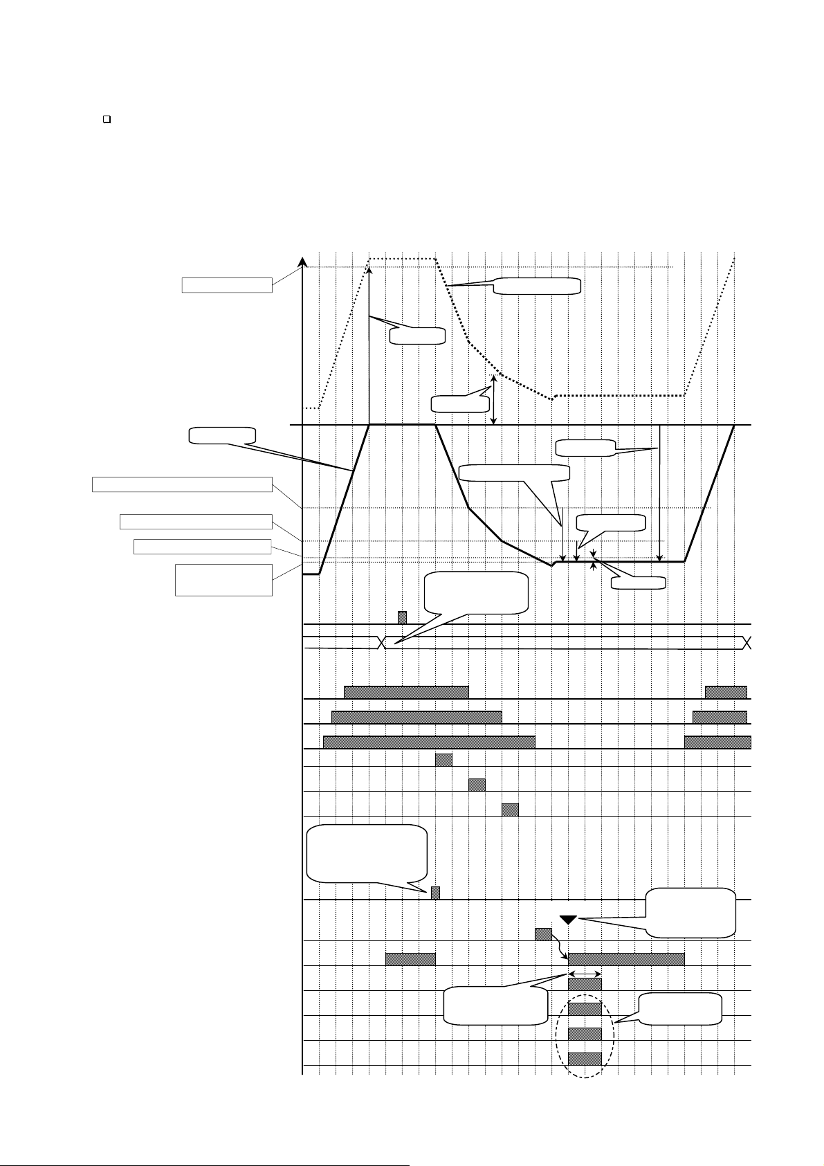
Advise
r
r
5qf-33
o
Using the automatic switch of normal batch and loss-in weight.
Specify the output terminal for the hopper number in the material code on the I/O.
Specify the input terminal to change the mode on the I/O. [1n f-nn] [9]
Connect the output terminal to the input terminal.
Connect the output common terminal to the input common terminal.
Set the delay time above 0.1 second at [5qf-32] Batch start delay timer.
Weighing value
Full filling value
Net weight
- Final value + Optional preliminary
- Final value + Preliminary
- Final value + Free fall
- Final value
or -Target weight
Tare command, Input
Material code, Input
Gross weight
Full filling
Zero band
0
Final value
Optional preliminary
Preliminary
The active code is
only read at each
start. And keep it.
Free fall
Full flow, Output
Medium flow, Output
Dribble flow, Output
Full flow comparison interrupt timer
5qf-34
Medium flow comparison interrupt time
5qf-35
Dribble flow comparison interrupt timer
Start command, Input
5qf-37
Eval delay timer
Stable, Output
Batch finish, Output
Over weight, Output
Acceptable, Output
Under weight, Output
If this command is
used, accumulation
and comparison can
be used.
5qf-43
Batch finish output
n
Comparison
Waiting time
and stable.
Set the condition
at 5qf-13
Select a mode
at 5qf-05
AD-4402 Page 63
Page 66

7.5.
7.5. Other Functions
7.5.7.5.
7.5.1.
7.5.1. Re-Zero
7.5.1.7.5.1.
Performing the function, a gross display is zeroed and an current weighing value is
used as a standard point.
The operation of t he function can perform form the front key, the input terminal of the
I/O and command input.
The adjustable range i s based on the zero calibratio n and Zero range [genf- 6] of
the function list. The range is displayed in the unit of percentage of the weighing
capacity.
The re-zero data is stored in the memory without power supply.
Resetting the re-zero data, use the I/O t erminal or the F 1 ~ F4 key tha t is set to Zero
clear
nn: terminal number of I/O.
Other Functions
Other FunctionsOther Functions
Re-Zero Operation
Re-ZeroRe-Zero
[1n f-nn] [2].
Caution
When the internal A/D converter is out of range, the re-zero operation be not
performed and the error code ZR.ERR
Operation
Operation Operation
ZR.ERR is displayed.
ZR.ERRZR.ERR
Concerning Parameters of the Function
Changing the range to do the re-zero operation.
[genf- 6] Zero range
The maximum range is 30% of the capacity.
[Function] - [Function setting] - [General] - [Weighing]
Using the prohibition of the re-zero operation in the unstable condition.
[genf- 9] Tare and zero compensation at unstable status
[Function] - [Function setting] - [General] - [Weighing]
Turning on the display, the re-zero function is used.
[genf-13]
7.5.2.
7.5.2. Zero Tracking Function
7.5.2.7.5.2.
The function automatically traces the weighing deviation at nearly zero point and
keeps zero display of gross display.
Zero Tracking Function
Zero Tracking FunctionZero Tracking Function
Clear mode at power ON
[Function] - [Function setting] - [General] - [Weighing]
Concerning Parameters of the Function
Changing the time of zero tracking
[genf- 7] Zero tacking time
[Function] - [Function setting] - [General] - [Weighing]
Changing the range of zero tracking
[genf- 8] Zero tacking band width
[Function] - [Function setting] - [General] - [Weighing]
Page 64 AD-4402
Page 67

7.5.3.
7.5.3. Tare
7.5.3.7.5.3.
The relation of display is as follows:
Net = Gross - Tare
Tare
TareTare
Concerning Parameters of the Function
Prohibiting tare during unstable weighing
[genf- 9] Tare and zero compensation at unstable status
[Function] - [Function setting] - [General] - [Weighing]
Prohibiting tare during negative weighing
[genf-10] Tare at negative GROSS weight
[Function] - [Function setting] - [General] - [Weighing]
Resetting tare at turning on the indicator
[genf-13] Clear mode at power ON
[Function] - [Function setting] - [General] - [Weighing]
7.5.4.
7.5.4. Preset Tare (Fixed Tare Function)
7.5.4.7.5.4.
Preset Tare (Fixed Tare Function)
Preset Tare (Fixed Tare Function)Preset Tare (Fixed Tare Function)
The preset tare can store in each material code.
Concerning Parameters of the Function
Using preset tare
[genf-11] Preset tare
[Function] - [Function setting] - [General] - [Weighing]
Using preset tare for partial materi al code
[genf-12]
Classifying normal tare and preset tare on the serial data
[genf-16] Activiation of fixed tare action
7.5.5.
7.5.5. Customizing Function Key (Key Design
7.5.5.7.5.5.
Refer to 2.2.1. Keys of Front panel regarding key operation.
Refer to 10.4. Parameter List of Function list regarding key function.
Customizing Function Key (Key Design))))
Customizing Function Key (Key DesignCustomizing Function Key (Key Design
Preset tare=0
[Function] - [Function setting] - [General] - [Weighing]
[Function] - [Function setting] - [General] - [Weighing]
Concerning Parameters of the Function
Setting F1, F2, F3 and F4 keys
[0tHf- 2] to [0tHf- 5]
[Function] - [Function setting] - [General] - [Other]
AD-4402 Page 65
Page 68

7.5.6.
7.5.6. Customizing Sub Display
7.5.6.7.5.6.
Use default sub-display pattern, if you want to reset it.
Refer to 10.4. Parameter List of Function list regarding items.
Customizing Sub Display
Customizing Sub DisplayCustomizing Sub Display
Item index number to be displayed. 32 items of
name and number can be set in maximum.
At odd: Input the name of the selected item
using alphanumeric characters.
At even: Input the number concerning the item.
5ub f 1
Name of
the item
Sub F1-3 [name]
hopper /row/col/figure
19 0 16 5
Information of
key operation
Items to append to sub-display
Row and Colum Address
01234567891011121314151617181920212223242526
0
1
2
3
Row 0 and 2 is dot matrix display for alphanumerical charactor.
Row 1 and 3 is 7-segment display for numerical charactor.
Items to append to sub-display
Number Name and Number to Display the It em Row size Columsize Figures
0 Not displayed
1Material
2 Hopper
3 Tar ge t val ue or fi nal v alu e
4 Free fall
5 Prelimi nary
6 Optional preliminary
7Over
8 Under
9 Zero Band
10 Full filling
11 Tare
12 Supplementary flow open timer
13 Supplementary flow close timer
Resize the item selected.
0 to 3 0 to26 1 to12
Page 66 AD-4402
Page 69

Number Name and Number to Display the It em Row size Columsize Figures
14 Automatic Free Fall Compensation
15 Internal reserved
16 Internal reserved
17 Dribble supply at entrance
18 Medium supply at entrance
19 Accumulated weight
20 Accumulation counts
21 Recipe , rCode
22 Accumulated weight for recipe mode
23 Accumulation counts for recipe mode
Concerning Parameters of the Function
Setting sub-display
[5ubf- 1] [1] Weighing display
[Function] - [Function setting] - [General] - [Sub-display]
7.5.7.
7.5.7. Graphic Display
7.5.7.7.5.7.
Use to display a bar-graph in the sub-display.
Example:
Graphic Display
Graphic DisplayGraphic Display
75.00kg
material total count
Cset12 1500.841 150
■■■■■■■■■■■■■■■■
0 50 100
Concerning Parameters of the Function
Using bar graph display
[5ubf- 3] Bar graph location
[Function] - [Function setting] - [General] - [Sub-display]
Selecting ratio of graph disp lay
[5ubf- 4] Ratio of graph display
[Function] - [Function setting] - [General] - [Sub-display]
Bar graph
%
AD-4402 Page 67
Page 70

7.5.8.
7.5.8. Accumulation
7.5.8.7.5.8.
Accumulate weight data and weighing count of each material code or recipe code.
Concerning Parameters of the Function
Using F1 ~ F4 key for accumulation
[0tHf- 2] to [0tHf- 5]
Using the I/O terminals for accumulation
[1n f-nn] nn: terminal number of the I/O.
Using parallel terminals for accumulation
[05 f-nn] nn: terminal number of the option.
Accumulation Operation
AccumulationAccumulation
[Function] - [Function setting] - [General] - [Other]
[Function] - [Function setting] - [Control I/O] - [Input]
n: slot number installed the option.
[Function] - [Function setting] - [slot n] - [OP-05]
Operation
Operation Operation
7.5.9.
7.5.9. Undoing Accumulation Operation
7.5.9.7.5.9.
Assign a operation input to undo the last re sult.
Refer to 10.4. Parameter List of Function list regarding key function.
7.5.10.
7.5.10. Clearing (Deleting) Accumulation Data
7.5.10.7.5.10.
Accumulation data can delete (clear) using preset operation input.
There are four types of clearing the data.
Assign a operation input to undo the last re sult on the function list.
Refer to 10.4. Parameter List of Function list regarding key function.
Undoing Accumulation Operation
Undoing Accumulation OperationUndoing Accumulation Operation
Clearing (Deleting) Accumulation Data
Clearing (Deleting) Accumulation DataClearing (Deleting) Accumulation Data
Page 68 AD-4402
Page 71

7.5.11.
A
7.5.11. Error Message
7.5.11.7.5.11.
Error Message and Alarm
Error MessageError Message
When the indi cator detects an error in the weighing system, an error message is
displayed.
When the indicator becomes to preset condition, it is announced with the preset
alarm.
and Alarm
and Alarm and Alarm
Error message is displayed
Kind of Alarm and Error
There is the following priority.
Weighing sequence error < Zero error < Alarm 1 < Alarm 2
SQ.ERR ZR.ERR ALARM 1 ALARM 2
Kind No. Description
When the weighing can no t continue, m essage is displayed and the
sequence is stoped. Cope with cause and restart the weighing.
The weighing sequencei stoped.
0
Cope with cause and restart the sequence.
Safety check can not complete.
1
Check the safety.
Under weight or over weight.
2
Compensate weight and restart.
There is conflict in setpoint
3
Weighing
sequence
error
SQ.ERR
Check setpoint
Time over of batch weighing.
4
Check the gate and remains of hopper mat.
Time over of discharge.
5
Check the discharge gate.
The remain is not enough to weigh it.
6
Add the material.
Error no.Kind of error
Over or under
amount in the
result
Stop key
SQ.ERR
SQ.ERR
SQ.ERRSQ.ERR
Error no. Error no.
larm 1Weighing error
□■■■□
■□□□■
□□□□■
□□□■□
□□■□□
□■□□□
■■■■■
Out of range
Principle alarm links, when
plural alarm is active.
SQ.ERR
SQ.ERR
SQ.ERRSQ.ERR
ALARM 1
ALARM 1
ALARM 1ALARM 1
□□■□□
□■■□□
□□■□□
□□■□□
□□■□□
□□■□□
□■■■□
7 When the batch is started, the weight is full already.
Nozzle is touched to hopper.
8
Check the nozzle.
9 There is not tare (vessel) on the weighing pan.
AD-4402 Page 69
Page 72

Kind No. Description
When weighin g value can not set to zero wit h re-zero o r tare,
Zero error
ZR.ERR
message is displayed.
0 Dispaly can not be zeroed by zero compensation.
1 Dispaly can not be zeroed by tare operation.
When weighin g value is out of range and emergency sto p is
Alarm 1
ALARM 1
performed, the symbol is displayed.
1 Weighing value is out of range.
9 Emergency stop is performing.
It can not wegh. Check the weighing system.
Example: loadcell cable, connctors.
A/D converter is positve over counts.
1
Alarm 2
ALARM 2
Check the loadcell cable.
A/D converter is negative orver counts.
2
Check the loadcell cable.
RAM error.
4
Check backup battery
Page 70 AD-4402
Page 73

7.5.12.
7.5.12. Graphic Status Indicator
7.5.12.7.5.12.
Graphic Status Indicator
Graphic Status IndicatorGraphic Status Indicator
The indicator can display weighing status, result on the graphic indicator.
Graphic indicator
Over
□□□□□
□□□□□
□□□□□
□□□□□
□□■□□
□■■■□
■■■■■
□□□□□
□□□□□
□□□□□
□□□□□
□□□□□
□□□□□
□□□□□
Acceptable
□□□□□
□□□□□
□□□□□
□□□□□
□□□□□
□□□□□
■■■■■
■■■■■
□□□□□
□□□□□
□□□□□
□□□□□
□□□□□
□□□□□
Under
□□□□□
□□□□□
□□□□□
□□□□□
□□□□□
□□□□□
□□□□□
■■■■■
□■■■□
□□■□□
□□□□□
□□□□□
□□□□□
□□□□□
Full flow
■■■■■
■■■■■
■■■■■
■■■■■
□■■■□
□■■■□
□■■■□
□□□□□
□■■■□
□□□□□
□■■■□
□□□□□
■■■■■
Medium flow
Concerning Parameters of the Function
Using graphic indicator
[5ubf- 5] Activity indicator
[Function] - [Function setting] - [General] - [Sub display]
7.5.13.
7.5.13. Memory
7.5.13.7.5.13.
The indicator has two kinds of memory.
Flash memory The memory is used to store the important data without power
Memory Backup
MemoryMemory
Backup
Backup Backup
supply that the count of re-writing them is few.
Life of re-writing them is approximately 100,000 times or more.
Data example: Calibration data, Function data
■■■■■
■■■■■
■■■■■
■■■■■
□■■■□
□□■■□
□□■■□
□□□□□
□□■■□
□□□□□
■■■■■
■■■■■
■■■■■
Dribble flow
■■■■■
■■■■■
■■■■■
■■■■■
□■■■□
□□■□□
□□■□□
□□□□□
■■■■■
■■■■■
■■■■■
■■■■■
■■■■■
Backuped RAM The memory is used to store temporary data that the count of re-
writing them is many.
Life of battery is approximately 10 years at 25 , normal use
Data example: Tare value, accumulation data, re-zero data
When re-writing data, the sequence is stopped.
Material code and recipe code can store in flash memory or backup RAM.
Concerning Parameters of the Function
Selecting the memory for material code or recipe code
[0tHf-11] Save data
[Function] - [Function setting] - [General] - [Other]
AD-4402 Page 71
Page 74

8.
A
A
A
8. Interface
8.8.
8.1.
8.1. Control I/O Function
8.1.8.1.
Input terminals 11 lines that can select the function
Output terminals 11 lines that can select the function
Interface
InterfaceInterface
Control I/O Function
Control I/O FunctionControl I/O Function
Open corrctor transister
Input terminal
Maximum typ.
Input open valtage 14V DC 8 V DC
Input drive current 5 mA 3 mA
Saturation tralance voltage 2 V DC
Output terminal
Maximum
Output valtage 40 V DC
Output current 50 mA
Saturation trelance voltage 1.5 V at 50 mA
8.1.1.
8.1.1. Interface circuit
8.1.1.8.1.1.
Interface circuit in
the indicator
Interface circuit
Interface circuitInterface circuit
Max. 8 ~ 14V
Max. 5 m
Max. 50 m
A1 ~ A 11
Input terminal
A12
Input common terminal
B1 ~ B 11
Output terminal
Vsat < 1.5 V at 50 m
B12
Output common terminal
or
Recommend you to use :
Mechanical switch or
Open collector transistor.
Vsat < 2 V
Max. 40V DC
or
Recommend you to use :
Mechanical relay with surge diode or
Photo coupler.
Use surge diode to protect
noise for solenoid and relay.
Page 72 AD-4402
Page 75

The function assigned to terminals
A
10ms/di
A
The function of the term inal can assign arbitrarily. Refer to 10.4. P aram et er l is t o f t he
Function list
8.1.2.
8.1.2. Timing Chart
8.1.2.8.1.2.
Timing Chart
Timing ChartTiming Chart
Caution
Keep the delay time to avoid mis-operation and noise.
Set the Communication mode in [01 f- 3] [without 5].
The transmission of BCD data synchr oniz es w ith display ing i t in the follow ing mod es.
Stream mode, auto print mode, manual print mode and accumulation print.
Exmaple
pprox. 10 ms from new
data edge to strobe signal.
Data output
Strobe signal
Hold input command
pprox. 20 ms width
Max. 50 ms delay
time until holding data
Max. 50 ms delay time to
release the hold command.
v
AD-4402 Page 73
Page 76

8.2.
A
A
A
8.2. Built-in RS-485 Interface
8.2.8.2.
The RS-485 interface can use command to control the indicator. The interface can
read weighing data or parameters or store parameter to the indicator.
The interface can con nect max. 32 u nits and a personal comp uter in a comm unication
cable.
These unit is specified by address appended to the command.
Transmission system EIA RS-485, Asynchronous, bi-d irectional, half-duplex
Data length 7 bis ot 8 bits
Start bit 1 bit
Parity bit Odd, Even, not used
Stop bits 1 bit, 2 bits
Baud rate 600 bps, 12000 bps, 2400 bps, 4800 bps, 9600 bps, 19200
Line 2 wires (2-balanced wires)
Connection Max. 32 units
Character code ASCII code
Terminator CR, CR LF
Built-in RS-485 Interface
Built-in RS-485 InterfaceBuilt-in RS-485 Interface
bps, 38400 bps
The way of Use and Note
When use terminator, connect between SDA and SDB terminals with accessory
resister.
If there is not signal ground at host computer, it is not necessry to use the SG
terminal.
If the shield cable is used, connect the FG teminal to shield line.
When connecting to RS-232C, Use AD-7491 or converter of RS-232C/ RS-485 on
market.
Use multi-droped connection for command mode.
Do not use multi-droped connection in stream mode or jet stream mode.
8.2.1.
8.2.1. Connection
8.2.1.8.2.1.
RS-485
SG
C.LOOP
Connection
ConnectionConnection
SDA
B
SDB
SG
D-4402 Inside
RE/DE
B
SG
FG
Shield
Terminals Interface Circuit
Page 74 AD-4402
Page 77

A
A
A
r
A
A
A
A
The host computer may have
inverse polarity terminals.
SD
Host compute
SDB
SG
FG
Terminator resistor
100 ~ 120
Ω 1/2W
The host computer may include
the terminator resistor.
D-4402
Address 1
D-4402
Address 2
D-4402
Address 32
SD
SDB
SG
FG
SD
SDB
SG
FG
SD
SDB
SG
FG
Use twist-pair wire.
Use shield cable, if it needs.
Connect terminator resistor at a
indicator where is longest dista nc e
from the host computer.
Terminator resistor
100 ~ 120Ω 1/2W
System Connections
8.2.2.
8.2.2. Settings of Parameters
8.2.2.8.2.2.
Refer to the 10.4. Parameter list of Function list.
Settings of Parameters
Settings of ParametersSettings of Parameters
AD-4402 Page 75
Page 78

8.2.3.
8.2.3. Timing Chart
8.2.3.8.2.3.
Timing Chart
Timing ChartTiming Chart
Keep delay time above 0.5 ms between last response and next command.
Set response time (tr). [r5 f- 9] < tr < [r5 f- 9] + 50 ms
Make long delay time, when there is noise.
Hi-Z: Hi impedance
Waiting time from command to
response: tr. Set tr at [
Host computer
AD-4402
Address 1
AD-4402
Address 2
Hi-Z
@01RW
Hi-Z
CRL
F
Communication Modes
There are the following modes.
Stream Mode
The data is output at every update of display. If the data can not output due to slow
baud rate completely, data is output at next update.
r5 f- 9].
@01ST,NT,+0123.45kg
Waiting time unitl next
command: td > 0.5 ms
Hi-Z
Hi-Z
CRL
@02RW
F
Waiting time from command to
response: tr. Set tr at [
CRL
F
Hi-Z
Hi-Z
@02ST,NT,+0123.45kg
r5 f- 9].
CRL
F
Auto Print Mode
The data is printed at batch finish and recipe finish automatically.
Accumulation Print Mode
When accumulating it or canceling the last result, the result of batch finish and recipe
finish is printed.
Manual Print Mode
When the preset print ke y or terminal is pressed, da ta is output.
Command Mode
The mode is used to contro l the indicator, to store parameters and to read data or
parameter.
Jet Steam Mode
The weighing data and state is output on 100 time/s. Data is gross or net value. The
format is the same as command RGRS or RNET.
Set baud rate to 38400 bps.
When slow baud rate is 1/2n times 38400 bps, the same data is output 2n times
Page 76 AD-4402
Page 79

8.2.4.
A
8.2.4. General Data Format
8.2.4.8.2.4.
General Data Format
General Data FormatGeneral Data Format
This format is used at command mode and jet stream mode.
12345678910111213141516171819202122232425262728
RGRS0099,1234567,123456789
CRL
F
Header Code W eighing data
Header
Command is replayed. The replayed command is 4 characters
Code
Material code or recipe code number. The code is 4 characters
Weighing data
Data uses BCD code, is 7 figures and is not include decimal point.
When data is negative, mi nus sign is appended to the h ead.
Example: 23 22 21 2
System Monitor
1 2 8 976543
20:Stable
21: Zero band
22: Full filling
3
: Full flow
2
20: Under
21: Internal reservation
22: Internal reservation
3
:Mixture
2
20: Mixture finish
21: Nozzle down
2
2
:Online
3
2
: During weighing sequence
20: Zero error
1
: Out of range
2
2
2
: Buzzer
3
2
:During tare
Internal reservation
SCII code = 3Ah.
Upper 4 bits are 3h always.
20: Medium flow
21:Dribble flow
22:Over
3
2
: Acceptable
20: Discharge gate
21: Weighing finish
22: Recipe finish
3
2
: Discharge finish
20: Internal reservation
1
2
: Weighing error
22:Alarm 1
3
:Alarm 2
2
20: Center of zero
21: Gross display
22: net display
3
2
: During hold
Terminator
System Monitor
0
1 0 1 0 = Ah
Terminator
CR or CR + LF CR: 0Dh, LF: 0Ah
AD-4402 Page 77
Page 80

8.2.5.
A
8.2.5. A&D Data Format
8.2.5.8.2.5.
The format is used for stream mode, auto print mode and accumulation print.
The format is compatible to the indicator AD-4325.
1 2 3 4 5 6 7 8 9 101112131415161718
ST,NT,+0012.34kg
A&D Data Format
A&D Data FormatA&D Data Format
CR LF
Header 1
Header 1
ST Stable
US Unstable
LO Out of range
Header 2
GS Gross value
NT Net value
TR Tare value
Weighing data
Data uses BCD code, is 7 figures and is include de cimal point.
When data is negative, mi nus sign is appended to the h ead.
When data is out of range, all n umerical characters are space (20h).
Unit
Kg, g or t
Header 2
Weighing data
Unit
Terminator
Terminator
CR or CR + LF CR: 0Dh, LF: 0Ah
8.2.6.
8.2.6. Address
8.2.6.8.2.6.
Set the address in [r5 f- 8].
32 indicators can connect to a computer.
There is not relation between communica tion mode [r5 f- 2] and address [r5 f- 8].
Address
AddressAddress
Broadcast Address
When address @oo is used, send a command to all indicators in the same time.
Exmaple:
@0 0CTAR
CR LF
ddress
Page 78 AD-4402
Page 81

8.2.7.
8.2.7. Command List
8.2.7.8.2.7.
Command List
Command ListCommand List
Monitor Commands
Name Code Description
Read weighing value
Read gross data RGRS
Read net value RNET
Read Tare value RTAR
Read weighing result
Read setpint or
Read comparison parameters
Read material code RCODxxxx To read the details of the code. # 1
Read recipe code RRCDxxxx To read the details of the code. # 1
Read accumulation data
of material code
Read accumulation data
of recipe code
Read error code RERR
RDSP
RW
RFIN
RF #1
RSPTxxxx
RSPT####
RSxx #1
RTTLxxxx
RRTLxxxx
xxxx: Material code or recipe code.
#1: Compatible command to AD4401, AD-4403 and AD4325.
Write Commands
Name Code Description
Store setpoints
Store comparison parameters
Store material code WCODxxxx To store all parameters of the code.
Store recipe code WRCDxxxx To store all parameters of the code.
xxxx: Material code or recipe code.
####: When reading an active material code or recipe code during the sequence,
place four space codes (ASCII 20h).
%%%%
: When storing new para mete rs to ma terial cod e or rec ipe cod e that is re calle d
as next code in the sequen ce, place four space codes (ASCII 20h).
#1: Compatible command to AD4401, AD-4403 and AD4325.
WSPTxxxx
WSPT
SSxx #1
SA
%%%%
To store optional preliminary and zero
band. #1
AD-4402 Page 79
Page 82

Control Commands
Name Code Description
Make zero display
Make zero clear CCZR
Tare
Tare clear
Change to gross display
Change to net displa y
Call material code
Call recipe code CRCDxxxx
Accumulation command
Cancel the last result
Batch start
Discharge start
Recipe start CBLD
Mixture start CMIX
Re-start CRES
Stop CHLT
Emergency stop
Clear accumulation data
of material code
Clear accumulation data
of all material code
Clear accumulation data
of recipe code
Clear accumulation data
of all recipe cod e
Reset an error CRER
No operation CNOP
CZER
MZ #1
CTAR
MT #1
CCTR
CT #1
CGRS
MG #1
CENT
MN #1
CCODxxxx
CCxx #1
CACC
AM #1
CCAC
CA #1
CBAT
BB #1
CDSC
BD #1
CSTP
HB #1
CDTLxxxx Accumulation data is set to 0.
DTxx Accumulation data is set to 0. #1
CETL All accumulation data is set to 0.
ET All accumulation data is set to 0. #1
CDRTxxxx Accumulation data is set to 0.
CERT All accumulation data is set to 0.
xxxx: Material code or recipe code.
#1: Compatible command to AD4401, AD-4403 and AD4325.
Page 80 AD-4402
Page 83

Response Error Code
Response Description Note
?E T he format of command is not correct.
VE The data of command is not correct.
IE Indicator is busy.
ASCII Code for AD-4402
The characters are special code for the name of material code and recipe code.
Therefor, some characters are not the same as U.S. code.
01234567
0
1
2
3
4
5
6
C
D
A
B
E
F
7
8
9
LF
CR
Upper bits
When address is used,
address is appended to the
response, too.
Lower bits
Space
0@P
Space
p
!1AQaq
"2BRbr
#3CScs
$4DTdt
%5EUeu
&6FVf v
'7GWgw
(8HXhx
)9IYiy
*:JZjz
+;K[k{
,<L l|
-=M]m}
.>N^n
/?O_o
AD-4402 Page 81
Page 84

8.3.
A
A
8.3. Built-in Current Loop
8.3.8.3.
Transmission system EIA RS-232C, Asynchronous, bi-directional, half-duplex
Current 1 = 20mA, 0 = 0 mA, external DC current source
Data length 7 bis
Start bit 1 bit
Parity bit Even
Stop bits 1 bit
Baud rate 600 bps, 12000 bps, 2400 bps
Code ASCII code
8.3.1.
8.3.1. Connection
8.3.1.8.3.1.
Built-in Current Loop Output
Built-in Current LoopBuilt-in Current Loop
Connection
ConnectionConnection
Output
Output Output
RS-485
B
SG
C.LOOP
FG
The current loop output has not polarity.
Use an external DC current source.
Connect the FG terminal when using the shield cable.
8.3.2.
8.3.2. Communication Modes
8.3.2.8.3.2.
There are the following modes.
Current loop Output
Current loop Output
Shield
Communication Modes
Communication ModesCommunication Modes
D-4402 inside
The CURRENT
LOOP terminals
have not polarity.
Stream Mode
The data is output at every update of display. If the data can not output due to slow
baud rate completely, data is output at next update.
Auto Print Mode
The data is printed at batch finish and recipe finish automatically.
Manual Print Mode
When the preset print ke y or terminal is pressed, da ta is output.
Accumulation Print Mode
When accumulating it or canceling the last result, the result of batch finish and recipe
finish is printed. When canceling the last result, the inverse polarity data is output.
Page 82 AD-4402
Page 85

8.3.3.
A
A
A
A
8.3.3. Data Format
8.3.3.8.3.3.
The format is the same as A&D format of the built-in RS-485.
8.4.
8.4. BCD Output
8.4.8.4.
Output circuit Open collector transistor
Output voltage 40 V DC max.
Output saturation voltage 0.8 V at 25 mA
Input control Contact to ground
Input open voltage 5 V DC
Input current 5 mA max.
Threshold voltage 1.5 V max.
Data Format
Data FormatData Format
BCD Output of Option, OP-01
BCD OutputBCD Output
of Option, OP-01
of Option, OP-01 of Option, OP-01
5%
Connection
5V±5%
B20
20
1
D-4402,
OP-01 inside
max.
5mA
25mA max.
Hold
B18
Output
A1 to A18
B1 to B17
Vsat < 0.8V
at 25mA
19、B19
Common terminals
max.
DC40V
Recommend to use
PLC or Photo coupler.
AD-4402 Page 83
Page 86

Terminals
When weighing display, gross display, net display and tare display [01f- 1] [1,
2, 3, 4] is used, the function of terminals are as follows:
A1 1 B1 2
A2 4 B2 8
A3 10 B3 20
A4 40 B4 80
A5 100 B5 200
A6 400 B6 800
A7 1,000 B7 2,000
A8 4,000 B8 8,000
A9 10,000 B9 80,000
A10 40,000 B10 80,000
A11 100,000 B11 200,000
A12 400,000 B12 800,000
A13 Over B13 Positive polarity
A14 Stable B14 Net
A15 Decimal point 0.0 B15 Decimal point 0.0
A16 Decimal point 000.0 B16 Decimal point 000.0
A17 Unit 1 B17 Unit 2
A18 Strobe B18 Hold input
A19 Common ground B19 Common ground
A20 Frame ground B20 Frame ground
Unit Unit 1 Unit 2
blank
kg
t
g
00
00
01
11
When accumulation weight and accumulation counts [01f- 1] [5, 6, 7, 8] is used,
the function of terminals are as follows:.
A1 1 B1 2
A2 4 B2 8
A3 10 B3 20
A4 40 B4 80
A5 100 B5 200
A6 400 B6 800
A7 1,000 B7 2,000
A8 4,000 B8 8,000
A9 10,000 B9 80,000
A10 40,000 B10 80,000
A11 100,000 B11 200,000
A12 400,000 B12 800,000
A13 1,000,000 B13 2,000,000
A14 4,000,000 B14 8,000,000
A15 10,000,000 B15 20,000,000
A16 40,000,000 B16 80,000,000
A17 Over B17 Positive polarity
A18 Strobe B18 Hold input
A19 Common ground B19 Common ground
A20 Frame ground B20 Frame ground
Page 84 AD-4402
Page 87

When recipe code and material code [01f- 1] [9] is used, the function of termin als
are as follows:.
A1 1 B1 2
A2 4 B2 8
A3 10 B3 20
A4
A5 1 B5 2
A6 4 B6 8
Material code at
weighing
sequence
Referred
material code
40 B4
Material code at
weighing sequence
80
Referred material code
A7 10 B7 20
A8
A9 1 B9 2
A10 4 B10 8
A11 10 B11 20
Recipe code at
weighing
sequence
A12
A13 1 B13 2
A14 4 B14 8
Referred recipe
code
40 B8
40 B12
80
Recipe code at
weighing sequence
80
Referred recipe code
A15 10 B15 20
A16
40 B16
80
A17 B17
A18 Strobe B18 Hold input
A19 Common ground B19 Common ground
A20 Frame ground B20 Frame ground
When Error and alarm [01f- 1] [10] is used, the function of terminals are as follows:.
A1 1 B1 2
A2 4 B2 8
Sequence error
number
Sequence error
number
A3 Error B3
A4
A5 1 B5 2
A6 4 B6 8
Zero error
number
B4
Zero error number
A7 Error B7
A8
A9 1 B9 2
Alarm 1 number
B8
Alarm 1 number
A10 4 B10 8
A11 Error B11
A12
A13 1 B13 2
Alarm 2 number
B12
Alarm 2 number
A14 4 B14 8
A15 Error B15
A16
B16
A17 B17
A18 Strobe B18 Hold input
A19 Common ground B19 Common ground
A20 Frame ground B20 Frame ground
AD-4402 Page 85
Page 88

Communication Modes
A
f
A
A
A
There are the following modes.
Stream Mode
The data is output at every update of display. If the data can not output due to slow
baud rate completely, data is output at next update.
Auto Print Mode
The data is printed at batch finish and recipe finish automatically.
Manual Print Mode
When the preset print key or terminal is pressed, da ta is output.
Accumulation Print Mode
When accumulating it or canceling the last result, the result of batch finish and recipe
finish is printed. When canceling the last result, the inverse polarity data is output.
Jet Steam Mode
The weighing data and state is output on 100 time/s. Data is gross or net value. The
format is the same as command RGRS or RNET.
Set baud rate to 38400 bps.
When slow baud rate is 1/2n times 38400 bps, the same data is output 2n times
Timing Chart
When normal output [01f- 3] [without 5] is used
pprox. 10 ms from data
input to strobe
Data Output
Strobe
Hold input
When normal output [01f- 3] [without 5] is used
pprox. 1 ms from
data input to strobe
Data Output
Strobe
Hold input
pprox. 20 ms o
pulse width.
pprox. 2 ms of pulse
width.
50 ms of delay
time to hold it.
50 ms of delay time
to release it
10ms/div
Ignored hold
signal
2ms/div
Page 86 AD-4402
Page 89

8.5.
A
8.5. Relay Output
8.5.8.5.
Rated load 250 V AC, 3 A
Current at common term inal Max. 10A DC
Minimum load 100 mV 100 µA
Life 20,000,000 times or more at no load
Relay Output of Option, OP-02
Relay OutputRelay Output
of Option, OP-02
of Option, OP-02 of Option, OP-02
30 V DC, 3 A
100,000 times or more at rated load
Connection
D-4402
OP-02 inside
Group 1
1 Output terminal
2
3
4
5
6 common terminal 1
Group 2
Terminal List
Refer to 10.4. Parameter list of the function list.
7 Output
8
9
10
11 common terminal 2
AD-4402 Page 87
Page 90

8.6.
A
A
A
R
8.6. RS-422/485 Interface of Option, OP-03
8.6.8.6.
RS-422/485 Interface of Option, OP-03
RS-422/485 Interface of Option, OP-03RS-422/485 Interface of Option, OP-03
The RS-422/485 interface can use command to control the indicator. The interface
can read weighing data or parameters or store parameter to the indicator.
The interface can con nect max. 32 u nits and a personal comp uter in a comm unication
cable.
These unit is specified by address appended to the command.
TS-485 can use 2-wire or 4- wire.
The command and format is the same as the built-in RS-485.
Transmission system EIA RS-422 / 485,
Asynchronous, bi-directional, half-duplex
Data length 7 bis ot 8 bits
Start bit 1 bit
Parity bit Odd, Even, not used
Stop bits 1 bit, 2 bits
Baud rate 600 bps, 12000 bps, 2400 bps, 4800 bps, 9600 bps, 19200
bps, 38400 bps(Jet stream mode)
Line RS-422: 4 wires
RS-485: 2 wires or 4 wires
Connection Max. 32 units
Character code ASCII code
Terminator CR, CR LF
Caution
The option can install either OP-03 or OP-04
Connection
Terminator switch
SD
SDB
RD
RDB
SG
FG
422/485
DE/RE
AD-4402
OP-03 inside
SD
RD
1 SD
2 SDB
TERMI NATO
100Ω
3 RDA
4 RDB
5 SG
6 FG
FG
Page 88 AD-4402
Page 91

RS-422 Connections
A
A
A
A
A
A
Settings RS-422 [03 f-11] [1]
Address Number 0 [03 f- 8] [0].
Terminator resistor
100 ~ 120
Host computer
SDA 1
SDB 2
RDA 3
RDB 4
SG 5
FG 6
Ω 1/2W
The host computer may include
the terminator resistor.
D-4402 TERMINATOR
ON
OFF
Turn on terminator
switch
SDA 1
SDB 2
RDA 3
RDB 4
SG 5
FG 6
RS-485 4 Wire Connections
Settings RS-422 [03 f-11] [1]
Address Number [03 f- 8] [without 0].
Terminator resistor
Host computer
D-4402
No.1
TERMINATOR
SDA
SDB
RD
RDB
SG
FG
ON
OFF
SDA
SDB
RD
RDB
SG
FG
100 ~ 120
The host computer may have
inverse polarity terminals.
Use twist-pair wire.
Use shield cable, if it needs.
The host computer may
Ω 1/2W
The host computer may have
inverse polarity terminals.
Use twist-pair wire.
Use shield cable, if it needs.
include the terminator
D-4402
No.32
AD-4402 Page 89
TERMINATOR
ON
ON
ONON
OFF
SDA
SDB
RD
RDB
SG
FG
Connect terminator resistor
at a indicator where is
longest distance from the
host computer.
Page 92

RS-485 2 Wire Connections
A
A
A
A
Settings RS-485 [03 f-11] [2]
Host computer
D-4402
TERMINATOR
No.1
D-4402
TERMINATOR
No.32
FG
ON
OFF
OFF
OFFOFF
SDA
SDB
RD
RDB
SG
FG
ON
ON
ONON
OFF
SDA
SDB
RD
RDB
SG
FG
Terminator resistor
100 ~ 120
A
B
Ω 1/2W
The host computer may have
The host computer may include
the terminator resistor.
inverse polarity terminals.
2 (SDA) and 3 (SDB)
connect nothing.
Use twist-pair wire.
Use shield cable, if it needs.
Connect terminator resistor
at a indicator where is
longest distance from the
host computer.
Turn on
terminator switch
Settings of Parameters
Refer to 10.4. Parameter list of the function list.
Timing Chart
Keep delay time above 0.5 ms between last response and next command.
Set response time (tr). [03 f- 9] < tr < [03 f- 9] + 50 ms
Make long delay time, when there is noise.
Make 4 ms or more from output finish to receiveing next command
Hi-Z: Hi impedance
Host computer
AD-4402
Address 1
Waiting time from command to
response: tr. Set tr at [
Hi-Z
@01RW
CRL
F
Hi-Z
03 f- 9].
@01ST,NT,+0123.45kg
Waiting time unitl next
command: td > 4 ms
Hi-Z
CRL
F
@02RW
Waiting time from
command to response: tr.
03 f- 9].
Hi-Z
CRL
Set tr at [
F
Hi-Z
AD-4402
Hi-Z
@02ST,NT,+0123.45kg
CRL
F
Address 2
Page 90 AD-4402
Page 93

8.7.
A
8.7. RS-232C Interface of Option, OP-04
8.7.8.7.
RS-232C Interface of Option, OP-04
RS-232C Interface of Option, OP-04RS-232C Interface of Option, OP-04
The RS-232C is used to connect to the DEC (modem).
The command and parameters of RS-232C is the same as the built-in RS-485.
Transmission system EIA RS-232C,
Asynchronous, bi-directional, half-duplex
Data length 7 bis ot 8 bits
Start bit 1 bit
Parity bit Odd, Even, not used
Stop bits 1 bit, 2 bits
Baud rate 600 bps, 12000 bps, 2400 bps, 4800 bps, 9600 bps,
19200 bps
Caution
The option can install either OP-03 or OP-04
Connection
D-4402
25
OP-04 inside
FG
13
1
FG
2
TXD
14
1
Settings of Parameters
Refer to 10.4. Parameter list of the function list.
SG
3
4
5
6
7
20
RXD
RTS
CTS
DSR
SG
DTR
AD-4402 Page 91
Page 94

8.8.
A
A
8.8. Parallel I/O of Option, OP-05
8.8.8.8.
Use the option to extend I/O terminals
The function, settings, interface circuit and timing chart of the option is the same as
buit-in I/O terminal.
Input control Contact to ground
Input open voltage 7 ~ 11 V DC
Input current 5 mA max.
Input threshold voltage 2 V max.
Output circuit Open collector transistor
Output voltage 40 V DC max.
Output saturation voltage 1.5 V at 50 mA
Parallel I/O of Option, OP-05
Parallel I/O of Option, OP-05Parallel I/O of Option, OP-05
Connection
A1 ~ A16 Input terminals
A17
A18
A19
A20 Frame ground
B1 ~ B16 Output terminals
B17
B18
B19
B20 Frame ground
Input common
Output common
B20
B1
20
1
Terminal List
Refer to 10.4. Parameter list of the function list.
Caution
Do not assign the same function to plural input teminals and keys.
Page 92 AD-4402
Page 95

8.9.
8.9. Analog Output of Option, OP-07
8.9.8.9.
Analog Output of Option, OP-07
Analog Output of Option, OP-07Analog Output of Option, OP-07
The option outputs DC current that is proportion to the display value.
It is adjusted by 4 mA output at zero display and 20 mA output at full scale.
Analog output Contact to ground
Output voltage 11 V DC min.
Adaptable resistance 0 Ω ~ 500 Ω
Update ratio 100 times per second with Sampling frequncy divider
[genf- 3]
Zero temperature coefficient 150 ppm/ max.
Span temperature coefficient 150 ppm/ max.
Non-linearlity 0.1% max.
Resolution smaller value of either 1/40000 or resoution of display
Connection
Span adjustment screw
adjusted in factory.
Zero adjustment screw
adjusted in factory.
Constant current source
Settings of Parameters
Refer to 10.4. Parameter list of the function list.
Output current
22mA
AD-4402
OP-07 inside
10V min.
Connect shield
The output voltage varies
according to resister value.
1
+
2
-
Resister
3
FG
20mA
When setting to
[
07 f- 2][100.00]
[
07 f- 3][0.00]
When setting to
[
07 f- 2][0.00]
[
07 f- 3][50.00]
2mA
AD-4402 Page 93
4mA
0.00kg
50.00kg
When setting to
[
07 f- 2][0.00]
[
07 f- 3][100.00]
Weighing
100.00kg
Page 96

9.
9. Maintenance
9.9.
9.1.1.
9.1.1. Basic Operation
9.1.1.9.1.1.
To enter the maintenance Press and hold the ENTER key and press the
To select an address of the parameter The , SHIFT + , ENTER, ESC keys.
To change the parameter The , SHIFT + , Alphanumerical, ENTER,
To exit the mode The ESC key.
(To return to weighing mode)
9.2.
9.2. Monitor Mode
9.2.9.2.
Maintenance
MaintenanceMaintenance
Basic Operation
Basic OperationBasic Operation
Monitor Mode
Monitor ModeMonitor Mode
key in weighing mode.
Select menu maintenance using the key and
the ENTER key.
ESC keys.
The monitor mode is used to check the indicator during the weighing sequence.
9.2.1.
9.2.1. Monitoring Control I/O Function
9.2.1.9.2.1.
Use to monitor the status of the I/O terminals.
Monitoring Control I/O Function
Monitoring Control I/O FunctionMonitoring Control I/O Function
123 kg
CONTROL 00010001000
When [
may not display all data.
9.2.2.
9.2.2. Monitoring Built-in RS-485 Interface
9.2.2.9.2.2.
genf- 1] is slow, it
Monitoring Built-in RS-485 Interface
Monitoring Built-in RS-485 InterfaceMonitoring Built-in RS-485 Interface
The current communication data are displayed.
Parity: p
Framing:f
a11 a1
I/O 00110100001
b11 b1
123 kg
RNET
Received data
Input terminal A1
Output terminal B1
RNET0099,1234567,123456789
r5-485 rcu and 5nd
Page 94 AD-4402
Sent data
Page 97

9.2.3.
9.2.3. Monitoring Built-in Current Loop Output
9.2.3.9.2.3.
The current communication data are displayed.
Monitoring Built-in Current Loop Output
Monitoring Built-in Current Loop OutputMonitoring Built-in Current Loop Output
Parity: p
Framing:f
9.2.4.
9.2.4. Monitoring A/D Converter
9.2.4.9.2.4.
The current A/D converter data are displayed.
Monitoring A/D Converter
Monitoring A/D ConverterMonitoring A/D Converter
RNET
ST,NT,+012.345kg
Current loop 5nd
123 kg
16.001 kg
Int.Count CAL:DS
Internal count
9.2.5.
9.2.5. Monitoring BCD Output of OP-01
9.2.5.9.2.5.
Monitoring BCD Output of OP-01
Monitoring BCD Output of OP-01Monitoring BCD Output of OP-01
160008
Received data
Sent data
DS: Enable
EN: Disable
The current BCD output data are displayed.
A18
12345 kg
OP-01 001111000100011011
a18 a1
B18
9.2.6.
9.2.6. Monitoring Relay Output of OP-02
9.2.6.9.2.6.
The status of the current relay outputs is displayed.
Output terminal
7 ~ 10
When [
may not display all data.
Monitoring Relay Output of OP-02
Monitoring Relay Output of OP-02Monitoring Relay Output of OP-02
genf- 1] is slow, it
001001000001010000
b18 b1
123 kg
OP-02 0001 10100
10 7 5 1
A1
B1
Output terminal
1 ~ 5
AD-4402 Page 95
Page 98

9.2.7.
9.2.7. Monitoring RS-422/485 Interface of OP-03
9.2.7.9.2.7.
The current communication data are displayed.
Monitoring RS-422/485 Interface of OP-03
Monitoring RS-422/485 Interface of OP-03Monitoring RS-422/485 Interface of OP-03
Parity: p
Framing:f
9.2.8.
9.2.8. Monitoring RS-232C Interface of OP-04
9.2.8.9.2.8.
The current communication data are displayed.
Parity: p
Framing:f
9.2.9.
9.2.9. Monitoring Parallel I/O of OP-05
9.2.9.9.2.9.
Monitoring RS-232C Interface of OP-04
Monitoring RS-232C Interface of OP-04Monitoring RS-232C Interface of OP-04
Monitoring Parallel I/O of OP-05
Monitoring Parallel I/O of OP-05Monitoring Parallel I/O of OP-05
RNET
RNET0099,1234567,123456789
0p-03 rcu and 5nd
RNET
RNET0099,1234567,123456789
0p-04 rcu and 5nd
123 kg
123 kg
Received data
Sent data
Received data
Sent data
The status of current parallel I/O is displayed.
123 kg
OP-05 1001000010001000
When [
may not display all data.
9.2.10.
9.2.10. Monitoring Analog Output of OP-07
9.2.10.9.2.10.
The current communication data are displayed.
genf- 1] is slow, it
Monitoring Analog Output of OP-07
Monitoring Analog Output of OP-07Monitoring Analog Output of OP-07
a16 a1
0101100110100001
b16 b1
96.27 kg
Analog output
OP-07
19.403 mA
Input terminal A1
Output terminal B1
Page 96 AD-4402
Page 99

9.3.
9.3. Test Mode
9.3.9.3.
The test mode is used to check the indicator and weighing system with test signal
output.
When the test mode is used, the weighing sequence is stopped.
Caution
The test mode outputs the test signal. Therfore, the devices connected to
system are influenced and it may cause mis-operation.
9.3.1.
9.3.1. Testing Control I/O Function
9.3.1.9.3.1.
Test the output of the I/O terminal. An active output of level "1" shifts for each
terminal.
Test Mode
Test ModeTest Mode
Testing Control I/O Function
Testing Control I/O FunctionTesting Control I/O Function
123 kg
CONTROL 00010001000
a11 a1
I/O 00100000000
b11 b1
Input terminal A1
Output terminal B1
9.3.2.
9.3.2. Testing Built-in RS-485 Interface
9.3.2.9.3.2.
When pressing the ENTER key each time, a test data "ST,GS,+0 000000kg CR LF" is
output.
9.3.3.
9.3.3. Testing Built-in Current Loop Output
9.3.3.9.3.3.
When pressing the ENTER key each time, a test data "ST,GS,+0 000000kg CR LF" is
output.
Testing Built-in RS-485 Interface
Testing Built-in RS-485 InterfaceTesting Built-in RS-485 Interface
123 kg
RNET
ST,GS,+0000000kg
r5-485 rcu and 5nd
Testing Built-in Current Loop Output
Testing Built-in Current Loop OutputTesting Built-in Current Loop Output
←↓
Received data
Sent data
RNET
ST,GS,+0000000kg
Current loop 5nd
AD-4402 Page 97
123 kg
←↓
Received data
Sent data
Page 100

9.3.4.
9.3.4. Testing A/D Converter
9.3.4.9.3.4.
The A/D converter data is displayed.
When pre ssing the ENTER key, a test voltage can be input to the A/D converter.
Testing A/D Converter
Testing A/D ConverterTesting A/D Converter
16.001 kg
A/D converter output
A/D Count L/C Output(mV/V)
964583 3.103872
Int.Count Test Input
160008 0ff
Loadcell output
Internal count
9.3.5.
9.3.5. Testing BCD Output of OP-01
9.3.5.9.3.5.
Test the output of the terminal. An active output of level "1" shifts for each terminal.
Testing BCD Output of OP-01
Testing BCD Output of OP-01Testing BCD Output of OP-01
A18
12345 kg
OP-01 000000000000000000
a18 a1
B18
9.3.6.
9.3.6. Testing Relay Output of OP-02
9.3.6.9.3.6.
Test the output of the terminal. An active output of level "1" shifts for each terminal.
Output terminal
7 ~ 10
Testing Relay Output of OP-02
Testing Relay Output of OP-02Testing Relay Output of OP-02
000001000000000000
b18 b1
123 kg
Test input
A1
B1
Output terminal
1 ~ 5
OP-02 0001 00000
10 7 5 1
9.3.7.
9.3.7. Testing RS-422/485 Interface of OP-03
9.3.7.9.3.7.
When pressing the ENTER key each time, a test data "ST,GS,+0 000000kg CR LF" is
output.
Parity: p
Framing:f
Testing RS-422/485 Interface of OP-03
Testing RS-422/485 Interface of OP-03Testing RS-422/485 Interface of OP-03
123 kg
RNET
ST,GS,+0000000kg
0p-03 rcu and 5nd
Page 98 AD-4402
←↓
Received data
Sent data
 Loading...