


NAUTICAST SOLAS AIS

AUTOMATIC IDENTIFICATION SYSTEM
Installation Manual
P/N 2607
Y1-03-0204 Rev H
ACR Electronics, Inc.
5757 Ravenswood Road
Fort Lauderdale, Fl 33312
+1(954) 981-3333
Fax +1 (954) 983-5087
www.acrelectronics.com
Email: Info@acrelectronics.com

Please read this first!
Warning:
Although ACR strives for accuracy in all its publications; this material may contain errors or
omissions, and is subject to change without prior notice. ACR shall not be made liable for any
specific, indirect, incidental or consequential damages as a result of its use. ACR
components may only be used in safety of life devices or systems, with the express written
approval of ACR, as the failure of such components could cause the failure of the ACR
device or system. If these fail, it is reasonable to assume that the safety of the user or other
persons may be endangered.
Copying of this document, and giving it to others and the use or communication of the contents
thereof, are forbidden without express authority. Offenders are liable to the payment of damages.
Weitergabe sowie Vervielfältigung dieser Unterlage, Verwertung und Mitteilung ihres Inhaltes
nicht gestattet, soweit nicht ausdrücklich zugestanden. Zuwiderhandlungen verpflichten zu
Schadenersatz.
Toute communication ou reproduction de ce document, toute exploitation ou communication
de son contenu sont interdites, sauf autorisation expresse. Tout manquement à cette règle
est illicite et expose son auteur au versement de dommages et intérêts.
Sin nuestra expresa autorización, queda terminantemente prohibida la reproducción total o
parcial de este documento, así como su uso indebido y/o su exhibición o comunicación a
terceros. De los infractores se exigirá el correspondiente resarcimiento de daños y perjuicios.
Installation Manual I Y1-03-0204 Rev. H

NAUTICAST Installation Manual
Index Page Number
1 GENERAL INTRODUCTION .................................................................................................................................................. 1
1.1 Description of AIS ......................................................................................................................................................... 1
1.2 AIS in an Operational Environment .............................................................................................................................. 2
1.3 AIS Networks ................................................................................................................................................................ 3
1.4 Carriage Requirement................................................................................................................................................... 4
1.4.1 Chapter V (Safety of Navigation) Regulation 19, of the SOLAS Convention.............................................................................. 4
1.4.2 Accelerated Implementation of AIS: .......................................................................................................................................... 4
2 NAUTICAST ........................................................................................................................................................................... 5
2.1 System Overview.......................................................................................................................................................... 5
3 INSTALLATION ...................................................................................................................................................................... 6
3.1 Installation Requirements ............................................................................................................................................. 6
3.2 Installation Overview..................................................................................................................................................... 6
3.3 General Interface Description....................................................................................................................................... 8
3.4 Interface NMEA Description: ........................................................................................................................................ 9
3.4.1 Sensor - Interface CH1, CH2, CH3 ........................................................................................................................................... 9
3.4.2 ECDIS – Presentation Interface CH 4 .......................................................................................................................................9
3.4.3 Pilot Port CH 5 ........................................................................................................................................................................ 10
3.4.4 Long Range CH 8 ................................................................................................................................................................... 10
3.4.5 DGPS – DGNSS Channel 9.................................................................................................................................................... 11
3.4.6 Alarm Circuit – BIIT Channel 10.............................................................................................................................................. 11
3.4.7 Proprietary Sentences............................................................................................................................................................. 11
3.5 Sensor Interface Definitions........................................................................................................................................ 12
3.5.1 Talker drive circuits................................................................................................................................................................. 12
3.5.2 Listener Receiver Circuits ....................................................................................................................................................... 12
3.5.3 Electrical isolation ................................................................................................................................................................... 12
3.5.4 Maximum voltage on the bus................................................................................................................................................... 12
3.5.5 Data transmission ................................................................................................................................................................... 12
3.6 Sensor notes............................................................................................................................................................... 13
3.7 Sensor Hardware Installation:..................................................................................................................................... 14
3.7.1 Installation of an RS422 serial interface: ................................................................................................................................. 14
3.8 Sensor Software Configuration................................................................................................................................... 15
3.8.1 Introduction ............................................................................................................................................................................. 15
3.8.2 Set up Sensor Speed, Checksum (CRC) and NMEA Talker and Sentence ID ........................................................................ 15
3.8.3 Real-Time Analysis of NMEA Data Streams............................................................................................................................ 18
3.8.4 Sensor Monitoring for Problem Analysis.................................................................................................................................. 20
3.8.5 Priority Handling of Sensor Sentence...................................................................................................................................... 21
3.8.6 Supported NMEA-0183 Sentences ......................................................................................................................................... 21
3.8.7 Calculated Values................................................................................................................................................................... 25
3.8.8 Versions of NMEA Sentences ................................................................................................................................................. 25
3.9 Pin-Description AIS-Cable / Socket 50-Pins:.............................................................................................................. 26
3.10 Pin-Description AIS-Connector:............................................................................................................................. 27
3.11 Installation of VHF / GPS Antennas....................................................................................................................... 28
3.11.1 VHF Antenna Installation......................................................................................................................................................... 28
3.11.2 GNSS Antenna installation...................................................................................................................................................... 29
3.12 Power Supply......................................................................................................................................................... 30
4 STARTING THE NAUTICAST.............................................................................................................................................. 31
4.1 Initial Set Up of the NAUTICAST for operation........................................................................................................... 31
4.2 Entering the MMSI and IMO Numbers........................................................................................................................ 31
4.3 Entering Ship Settings ................................................................................................................................................ 33
4.4 Entering Voyage Related Data ................................................................................................................................... 34
4.5 Service and User Passwords...................................................................................................................................... 36
5 TROUBLESHOOTING.......................................................................................................................................................... 39
5.1 Reading and understanding Alarms: .......................................................................................................................... 39
5.2 Alarm Codes ............................................................................................................................................................... 40
5.3 Text Messages........................................................................................................................................................... 41
5.4 Restarting the NAUTICAST ........................................................................................................................................ 41
6 ACCESSORIES.................................................................................................................................................................... 42
7 TECHNICAL INFORMATION ............................................................................................................................................... 43
8 CONTACT AND SUPPORT INFORMATION ....................................................................................................................... 44
9 APPENDIX............................................................................................................................................................................ 45
9.1 Samples for battery calculation................................................................................................................................... 45
9.1.1 Typical Installation................................................................................................................................................................... 45
9.1.2 RM GMDSS Compact-Console Area A3 with 250 W MF/HF ................................................................................................... 46
9.1.3 RM GMDSS Compact-Console Area A3 with 400 W MF/HF ................................................................................................... 46
9.2 Drawings and Approvals............................................................................................................................................. 47
Installation Manual II Y1-03-0204 Rev. H

History of Changes
Date
2003-04-30 1.0.2 A Released
2003-06-30 1.0.3 B Released
2004-06-03 1.0.4 C Released New Approvals, new pictures B. Werner
2004-07-09 1.0.5 D Draft Sensor Configuration A. Lesch
2004-07-14 1.0.5. E Draft ROT Gruber
2004-07-15 1.0.5. F Released Sensor Configuration Werner/Moore
2005-11-01 1.0.6 G Released GPS-Antenna, editorial work A. Lesch
2006-05-24 1.0.7 H Released Editorial work M. D’Arcangelo
Version Rev. Status
Comments
Dimensional drawings as Annex
Wheelmark Certificate as Annex
Amendments for:
Power consummation,
Troubleshooting, grounding,
external fuse, battery calculation
in Appendix
Responsible
A. Lesch
B. Werner
Installation Manual III Y1-03-0204 Rev. H

1 General Introduction
1.1 Description of AIS
What does the abbreviation AIS stand for?
AIS stands for: “Automatic Identification System”
What is AIS?
According to IALA regulations, AIS is defined as follows:
Very simply, the AIS is a broadcast Transponder system, operating in the VHF maritime
mobile Band. It is capable of sending ship information such as identification, position
course, speed and more, to other ships and to shore. It can handle multiple reports at
rapid update rates and uses Self-Organizing Time Division Multiple Access (SOTDMA)
technology to meet these high broadcast rates and ensure reliable and robust ship to ship
operation.
What are the performance standards of AIS?
The IMO defines the performance standards as follows:
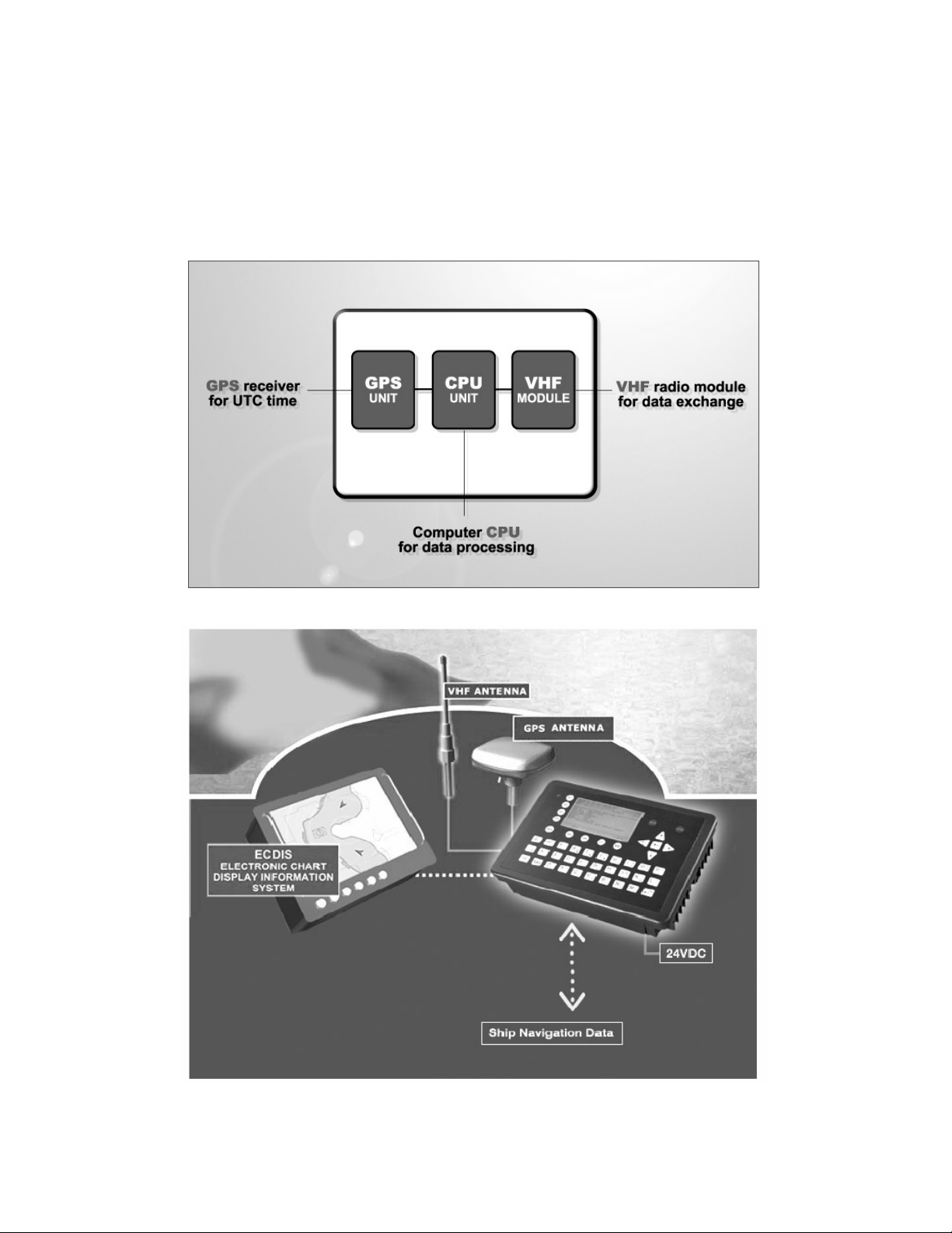
Which modules make up an AIS-Transponder?
The Modules:
Appropriate application software connects the individual modules.
In which modes does AIS function?
AIS are required to function flawlessly in a variety of modes. The relevant regulations require:
The system shall be capable of
- Ship to Ship working
- Ship to Shore working, including Long Range Application
- Automatic and continuous operation
- Provision of information messaging
- Utilization of maritime VHF channels
- DGPS / GPS receiver
- VHF Radio
- Antenna
- Computer (CPU)
- Power Supply
- An "autonomous and continuous" mode for operation in all areas. This mode
shall be capable of being switched to/from one of the following alternate modes by
a competent authority;
- An "assigned" mode for operation in an area subject to a competent authority
responsible for traffic monitoring such that the data transmission interval and/or
time slots may be set remotely by that authority;
- A "polling or controlled" mode, where the data transfer occurs in response to
interrogation from a ship or competent authority.
Installation Manual 1 Y1-03-0204 Rev.H
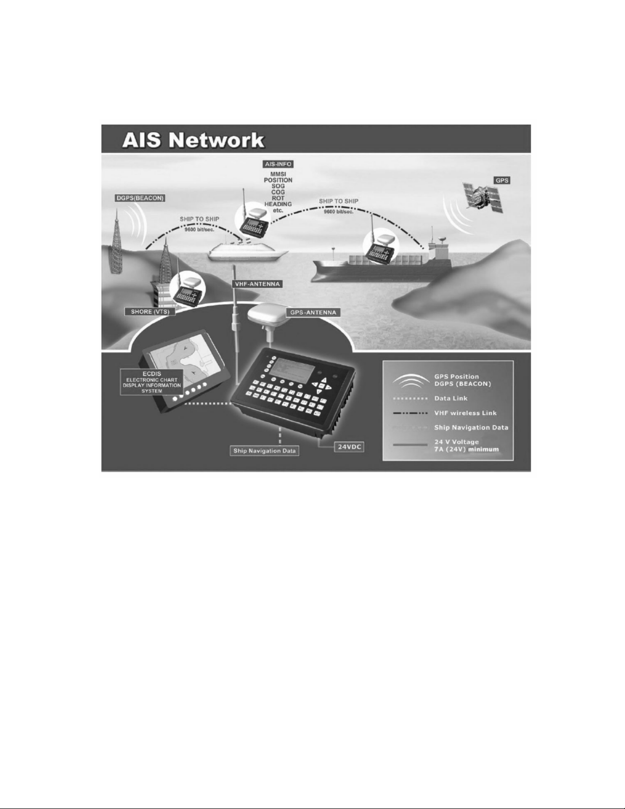
1.2 AIS in an Operational Environment
This illustration depicts a typical AIS System, where two or more AIS
equipped vessels (and shore based systems) are automatically
communicating with each other.
On the bottom, a typical NAUTICAST installation in a common environment is shown.
The NAUTICAST is connected to the vessels emergency power supply, and in
connection with the VHF, and GPS-Antennas, the minimal requirements for Transponder
operation are fulfilled.
Both vessels in the above illustration are equipped with a NAUTICAST (or any other
certified AIS-Transponder). Due to “Time – Synchronization” they use the same
organization of free and allocated windows (Slots) in the shared VHF Data Link (this
method is called “Self Organized Time Division Multiple Access”) to send and receive
messages.
Without the necessity of any active interaction, both vessels know exactly who or what is
cruising nearby and where the individual object is heading.
Installation Manual 2 Y1-03-0204 Rev.H
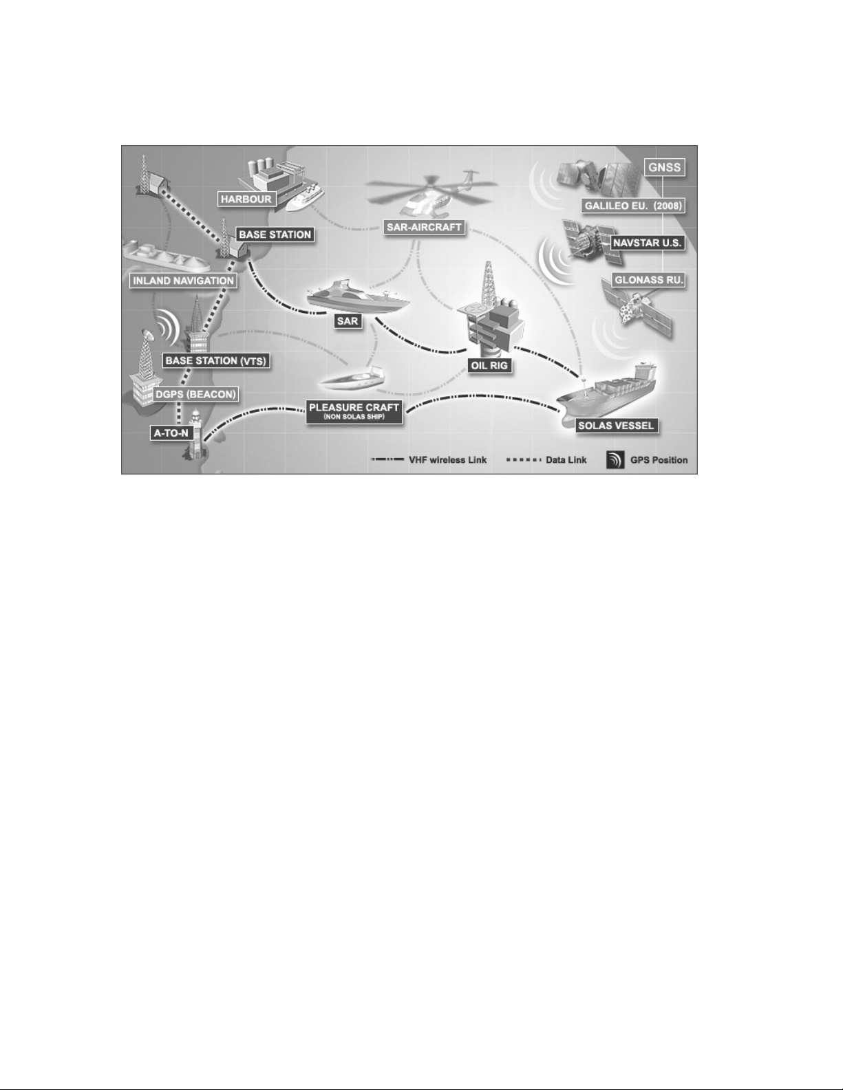
1.3 AIS Networks
The scenario below shows a full AIS coverage area (including all applications and complete
shore infrastructure).
The Carriage Requirement currently applies exclusively to SOLAS Vessels, but following the
current international discussions on maritime security; it is common understanding that other
possible AIS users will follow very soon. Shore Based infrastructure will be among the first
groups to become AIS equipped.
Installation Manual 3 Y1-03-0204 Rev.H

1.4 Carriage Requirement
1.4.1 Chapter V (Safety of Navigation) Regulation 19, of the SOLAS Convention.
IMO regulations require sea vessels from a size of 300 GT (Gross Tonnage) in international
and 500 GT in national waters to be equipped with an AIS-Transponder. The implementation
of this legislation began on July 1, 2002 and will be enforced in the following stages:
• July 2002 for all vessels built from this period onwards
• July 2003 for all passenger ships and all tankers which were built before July 1, 2002
• July 2004 for all ships of 50,000 GT and above which were built before July 1, 2002
• July 2005 for all ships from 10,000 GT up to under 50,000 which were built before
July 1, 2002
• July 2006 for all ships from 3,000 GT up to under 10,000 which were built before
July 1, 2002
• July 2007 for all ships from 300 GT up to under 3,000 which were built before
July 1, 2002
• July 2008 for all other ships which do not travel in international waters and were built
before July 2002
In some cases, exemptions may be granted to such ships, which will be taken off sea within 2
years of legislation coming into effect.
Refer to IMO Recommendation ITU-R M.1371-1 and IALA-AIS-Guidelines
1.4.2 Accelerated Implementation of AIS:
ANNEX
AMENDMENTS TO THE TO THE INTERNATIONAL CONVENTION FOR THE SAFETY OF
LIFE AT SEA, 1974 AS AMENDED CHAPTER V - SAFETY OF NAVIGATION
Regulation 19 - Carriage requirements for ship borne navigational Systems and equipment
states:
1 The existing subparagraphs .4, .5 and .6 of paragraph 2.4.2 are replaced by the
following:
“4 in the case of ships, other than passenger ships and tankers,
of 300 gross tonnage and upwards, but less than 50,000 gross tonnage, not
later than the first safety equipment survey' after 1 July 2004 or by 31
December 2004, whichever occurs earlier; and”
2 The following new sentence has been added at the end of the existing subparagraph
7 of paragraph 2.4;
“Ships fitted with AIS shall maintain AIS in operation at all times except where
international agreements, rules or standards provide for the protection of
navigational information.”
Refer to the International Convention for the Safety of Life at Sea, 1974 (SOLAS), held at
IMO, 9-13 December 2002
Installation Manual 4 Y1-03-0204 Rev.H
2 NAUTICAST
2.1 System Overview
Unlike other AIS devices, the NAUTICAST combines all required functions into one cabinet.
Additionally, the NAUTICAST gives the operator a number of additional features (easy
mounting & installation, environmental protection and smallest dimensions).
Installation Manual 5 Y1-03-0204 Rev.H

3 Installation
IMPORTANT: IMO REGULATIONS MANDATES that after the physical installation
has been successfully completed, all ships data and settings be entered into the AIS
transponder. See Section 4 for further instructions.
3.1 Installation Requirements
General Requirements
Please note that international conventions, regulations, instructions and guidelines have to be
adhered to when installing the NAUTICAST.
The following points must be observed before installation can commence:
- Permission by the local authority to install such a device must be granted.
- Trained service personnel must undertake the installation.
- The NAUTICAST must be fitted in a suitable place on the bridge.
- The VHF and GPS Antennas must be installed in a suitable position, where excellent
reception conditions apply (refer to Chapter 3.10 Installation of VHF antenna – page
28)
- All available interfaces must be installed.
- The vessels power supply must suffice, and the GMDSS power supply has to be
used.
- Installation of the pilot plug in conning position (close to the pilot working place).
3.2 Installation Overview
Survey
AIS is considered part of the ship’s radio station and is surveyed together with radio
installation. Surveys on SOLAS Convention ships should be carried out in accordance with
the rules laid down in IMO Res. A 746(18) "Survey Guidelines under the harmonized system
of survey and certification" (R) 8, and "Protocol of 1988 relating to the International
Convention for the Safety of Life at Sea, 1974."
The NAUTICAST consists of one unit, which integrates all necessary modules.
Installation Manual 6 Y1-03-0204 Rev.H
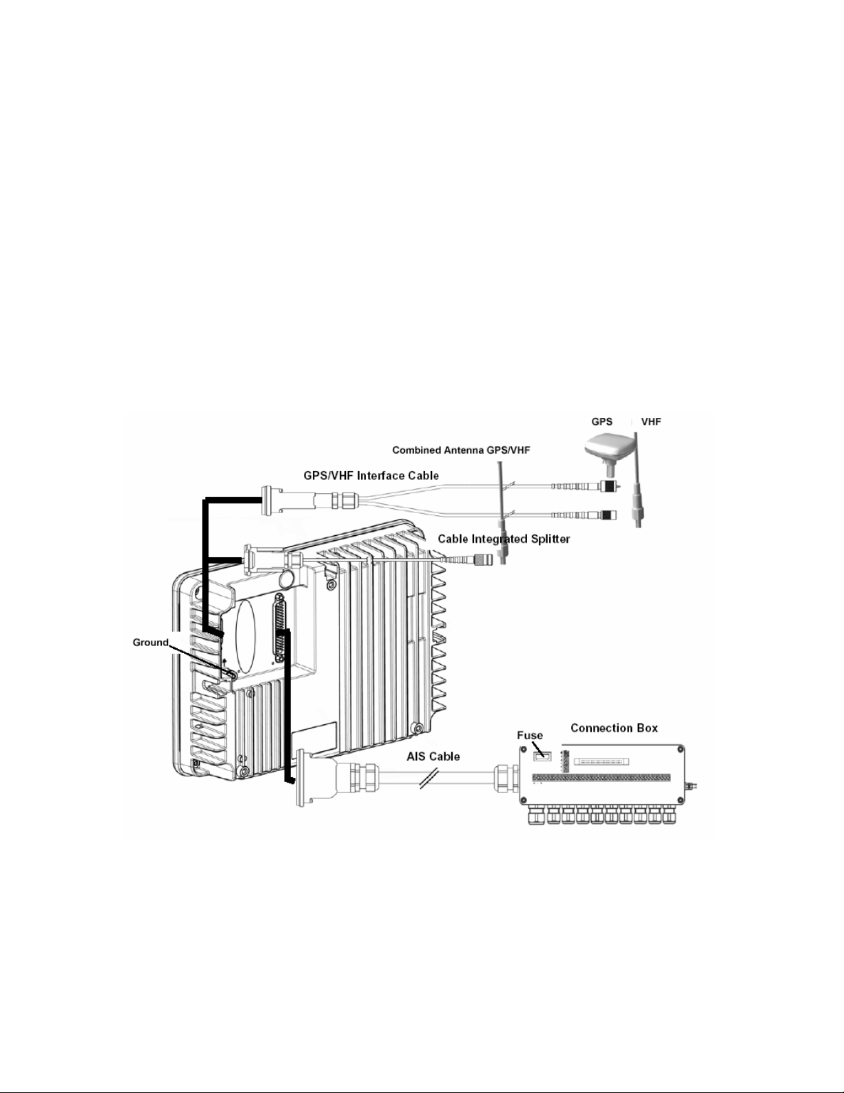
Step-by-Step Installation Procedure:
• Mount the NAUTICAST close to ships operation workstation for traffic surveillance and
maneuvering.
• Use the VHF adapter cable (P/N 2612) together with the VHF plug and TNC plug to
connect the VHF and GPS antenna cables and antennas.
• The sensors, ECDIS, PC, pilot case, long range devices and auxiliary displays can be
connected to the NAUTICAST cabinet by the AIS cable by means of the connection
box. The device is driven by a 24V DC 7A supply, which is connected to the power
terminal at the connection box. The AIS should be connected to an emergency power
source. A battery capacity calculation together with GMDSS-equipment is needed!
Please refer to Appendix 9.1 for examples of battery capacity calculations.
• After performing these steps, the NAUTICAST automatically starts operation.
• The NAUTICAST has a ground terminal which has to be connected to ship ground.
• Now configure the required initial system parameters according to Chapter 4 “Starting
the NAUTICAST” on page 31.
NAUTICAST Connection Diagram
Note: The ACR connection box includes a fuse of 6,3A. If it is not used, then the unit has to
be protected against high current by an external slow blow fuse of 6,3A.
Installation Manual 7 Y1-03-0204 Rev.H
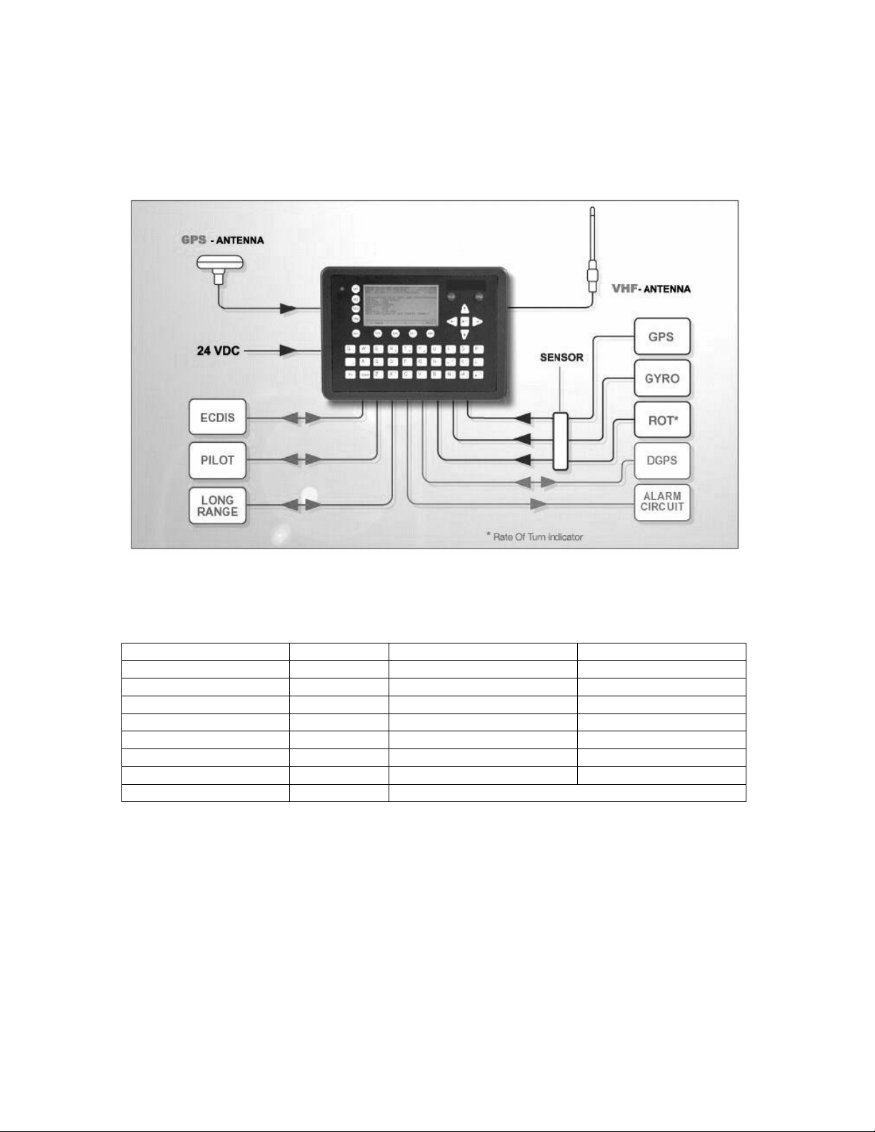
Components and Interfaces
The diagram below illustrates which devices can be connected to the NAUTICAST. For a
detailed description of sensor connecting e.g. an existing Gyro to the NAUTICAST refer to
Chapter 3 “Sensor Installation” on page 12.
3.3 General Interface Description
Interface Designation Speed Direction
Sensor 1 CH 1 4800bps or 38400bps Input
Sensor 2 CH 2 4800bps or 38400bps Input
Sensor 3 CH 3 4800bps or 38400bps Input
ECDIS CH 4 38400bps Input/Output
PILOT CH 5 38400bps Input/Output
LONG RANGE CH 8 38400bps Input/Output
DGPS (RTCM SC104) CH 9 9600bps Input/Output
ALARM CIRCUIT CH 10 Dry relay contact (power off and alarm state closed)
Installation Manual 8 Y1-03-0204 Rev.H

3.4 Interface NMEA Description:
3.4.1 Sensor - Interface CH1, CH2, CH3
Refer to Chapter 3.8 for detailed information on Sensor - Interface and Configuration.
3.4.2 ECDIS – Presentation Interface CH 4
Sentence Formatters
ABK
ACA AIS Channel assignment message in / out
ACK
AIR
ALR
ABM
BBM
DSC
DSE
DSI
DSR
LRI
LRF
SSD
TXT
VSD
VDM
VDO
UAIS Addressed and binary broadcast acknowledgement out
Acknowledge Alarm in
UAIS Interrogation Request in
Set Alarm State out
UAIS Addressed binary and safety related message in
UAIS Broadcast Binary Message in
Digital Selective Calling Information out
Expanded Digital Selective Calling out
DSC Transponder Initialize out
DSC Transponder Response out
UAIS Long-Range Interrogation out
UAIS Long-Range Function out
Station Static Data in
Text Transmission out
Voyage Static Data in
UAIS VHF Data-link Message out
UAIS VHF Data-link Own-vessel report out
Direction
Used Fields
All fields are provided
for Input and Output.
For further information
please refer to
IEC 61993-2 / NMEA
0183 HS V3.0 for
detailed field
information.
Installation Manual 9 Y1-03-0204 Rev.H

3.4.3 Pilot Port CH 5
The used sentence formatters for the pilot plug are the same as those listed for the ECDIS
port.
Note:
A pilot input/output port is part of an AIS Class A installation. A plug connected to this port
should be installed on the bridge near the pilot’s operating position, so that a pilot can
connect a Personal Pilot Unit (PPU) if required. Also, a power connector for the pilot unit
should be available nearby.
The pilot plug should be configured as follows: (Refer to SUB-COMMITTEE ON SAFETY OF
NAVIGATION NAV48/18 2.4.2002)
AMP/Receptacle (Square Flanged (-1) or Free-Hanging (-2)), Shell size 11, 9-pin,
Std. Sex 206486-1/2 or equivalent with the following connections:
- Tx A (out-) is connected to Pin 1
- Tx B (out+) is connected to Pin 4
- Rx A (in-) is connected to Pin 5
- Rx B (in+) is connected to Pin 6
- Shield is connected to Pin 9
3.4.4 Long Range CH 8
The AIS long range function requires a compatible long range communication system (e.g.
Inmarsat-C or MF/HF radio as part of GMDSS). This connection is required in order to
activate the long range function of the AIS. Its input/output port must meet the IEC 61162-2
requirements.
Sentence Formatters Direction
LRI UAIS Long Range Interrogation Input
LRF
UAIS Long-Range Function Input / Output
LR1
UAIS Long-Range Reply Sentence l Output
LR2 UAIS Long-Range Reply Sentence 2 Output
LR3
UAIS Long-Range Reply Sentence 3 Output
Field Information:
All fields are provided for input and output.
For further information please refer to
IEC 61993-2 / NMEA 0183 HS V3.0 for detailed field
information.
Installation Manual 10 Y1-03-020 4 Rev.H

3.4.5 DGPS – DGNSS Channel 9
Field / Protocol information:
All fields are provided with further information; please refer to ITU-R M.823-2 / RTCM SC 104
for detailed field information.
3.4.6 Alarm Circuit – BIIT Channel 10
The AIS requires that an alarm output (relay) must be connected to an audible alarm device
or the ships alarm system, if available.
Alternatively, the BIIT (built-in integrity test) alarm system may use the alarm messages
output on the presentation port (ECDIS Port Channel 5), provided the ECDIS alarm system is
connected and AIS compatible.
3.4.7 Proprietary Sentences
The proprietary ACR NMEA sentences have the NMEA registered manufacture talker ID
“NAU”. The $PNAU sentences are an addition to the standard sentences and offer other
manufactures full remote control to the Transponder. The additional “Extended NMEA
command set” – manual, which could be requested on demand, includes the full description
of how to use the proprietary NAUTICAST sentences.
Proprietary NMEA-Sentences $PNAU
MID - Mobile (MMS) Id
ASD - Advanced Ship Data
RCS - Read Configuration Settings
STO - Set Transponder Options
TSI - Transponder State Information
SCR - Sensor Configuration Request
SCA - Sensor Configuration Acknowledge
SCD - Sensor Configuration Data
SCM - Sensor Configuration Mode
RS - Reset Transponder
DT - Date and Time from the Transponder
AIQ - Request status information from the Transponder
Installation Manual 11 Y1-03-020 4 Rev.H

3.5 Sensor Interface Definitions
All interface ports of the NAUTICAST comply with IEC-61162-1 / -2 and NMEA-0183 HS 3.0
specifications (aligned to RS422 parameters).
3.5.1 Talker drive circuits
The maximum output current is I
requirements of ITU-T V.11.
3.5.2 Listener Receiver Circuits
Multiple listeners may be connected to a single talker. Optional termination resistors
(120Ohm) for the input lines are provided in the connection box. The input terminals A, B and
C are electrically isolated from the remaining electronics of the listening device.
The input impedance is 30kOhm between A and B lines, disregarding the connection of
termination resistors. The minimum input voltage is ±0,3V.
The listener's receiver circuit complies with ITU-T V.11.
3.5.3 Electrical isolation
= 50mA on each port. The drive circuit meets the
max
There are no direct electrical connections between the signal lines A and B.
The signal ground C must not be connected to the ship main ground or power line!
This isolation is in accordance with IEC 60945.
3.5.4 Maximum voltage on the bus
The maximum applied voltage between signal lines A and B and between either line and
ground C is in accordance with ITU-T V.11. For protection against incorrect wiring and for
unintended connection to older TALKER models, all receiver circuit devices are capable of
withstanding 15 V between both lines and signal ground for an indefinite period.
3.5.5 Data transmission
Data is transmitted in serial asynchronous form in accordance with IEC 61162-1. The first bit
is a start bit, and is followed by data bits, whereby the least significant bit is first.
The following parameters are used:
– Baud rate 38 400 (bits/s) 9600 (bits/s) 4 800 (bits/s)
– Data bits 8 (D7 = 0), parity none
– Stop bits 1.
Installation Manual 12 Y1-03-020 4 Rev.H

3.6 Sensor notes
External Sensor
The AIS has interfaces (configurable as IEC 61162-1 or 61162-2) for position, bottom track
(BT) speed, heading and rate of turn (ROT) sensors. In general, sensors installed in
compliance with other carriage requirements of SOLAS Chapter V should be connected to
the AIS System.*1. The sensor information transmitted by AIS should be the same
information being used for navigation of the ship. Interfacing problems might occur if the
existing on board sensors do not have serial (IEC 61162) outputs. A converter is needed to
translate the non conform data to IEC 61162 – sensor data. For Example ACR Converter
type P/N 2641.
The fact that AIS is fitted on board a vessel does NOT entail the need to install additional sensors
*1)
other than those stated in the carriage requirements.
External GPS
GNSS position sensors normally have IEC 61162 outputs suitable for direct AIS interfacing.
However, it is important to note that:
• The Geodetic Datum of the position data is transmitted by the sensor in WGS84 so that an
IEC 61162 DTM sentence is configured.
• AIS is able to process two reference points for its antenna position, one for external, and
one for an internal sensor. If more than one external reference point is used, the appropriate
information needs to be input to the AIS, so that the reference point information is suitably
adjusted.
External Heading
A gyrocompass providing heading information is a mandatory sensor input to the AIS. A
converter unit (synchro or step-signal converter to NMEA 0183 v.3.0 for example ACR
Converter type P/N 2641 will be needed for AIS connection in the case that the ship’s
gyrocompass does not provide IEC 61162 output.
External Speed and Course
If a bottom track (BT)log for speed over ground (SOG) is available, it may be connected. A
converter (for example ACR Converter type P/N 2641) is needed if the BT-log does not
provide IEC 61162 outputs
External Rate of Turn
Not all ships will carry a Rate-Of-Turn (ROT) indicator according to IMO A.526. However, if a
rate-of-turn indicator is available and it includes an IEC 61162 interface, it should be
connected to the AIS.
If ROT information is not available from a ROT indicator, it may (optionally) be derived from
heading information through:
• The gyrocompass itself,
• An external converter unit (see Heading),
• The AIS itself (calculated ROT).
Installation Manual 13 Y1-03-020 4 Rev.H
3.7 Sensor Hardware Installation:
3.7.1 Installation of an RS422 serial interface:
In most cases, the output from a GPS is already being used by existing navigation
equipment. It is possible to split an RS 422 output for two devices. If the signal becomes too
low, then an NMEA splitter has to be used.
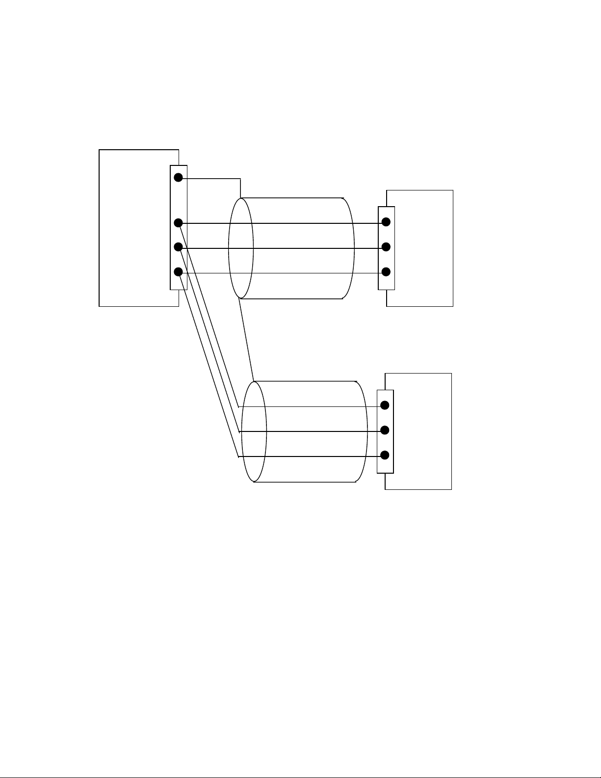
Example for single talk multi-listener connection:
Shields
A
B
C (GND)
Talker (e.g.: GPS)
- IN
+ IN
(or 2,3)
G1
AIS Conncetion Box
A
B
C (GND)
Listener (other
equipment)
Each interface on the Transponder is a RS422 serial interface
The shield or ship main ground should not be connected with the signal ground (GND).
Installation Manual 14 Y1-03-020 4 Rev.H
3.8 Sensor Software Configuration
3.8.1 Introduction
The AIS NAUTICAST requires a connection to various sensor devices. Sensor Configuration
should enable compatibility with existing navigation devises aboard any vessel.
This chapter deals with several ways to configure the NAUTICAST and to comply with the
requirements of the specific sensor interfaces.
Configuration and display is visible on two screens of the Sensor Configuration Menu. The
NAUTICAST offers the following configuration options:
• Set up data speed 4800/9600/38400 baud.
• Monitor the connected sensor inputs for each sensor channel.
• Verify and edit the Sensor Configuration on the display screen.
• Analyze the information received from the connected sensor devices.
• Produce an electronic installation report.
• Configuration of various NMEA protocols.
The individual options may be repeated until the required configuration for the connected
sensor devices is achieved.
During the configuration process, the NAUTICAST is not operational.
3.8.2 Set up Sensor Speed, Checksum (CRC) and NMEA Talker and Sentence ID
Sensor configuration is available in the AIS software versions higher than 2.0.1.0. It is
accessible via the new submenu ‘5. Sensor Settings’ in the Service Password protected
menu: ‘5. Transponder Configuration’.
N 1o19' E 0o13' |1> N/A|2>0.00|3>0.10nm
|--------------------------------- | 5. Transponder Configuration
-----| |
| +- 1. Change User Password
View | +- 2. Region Settings
| +- 3. Alarm Settings
-----| +- 4. Interrogation Settings
| +- 5. Sensor Settings
Msg. | +- 6. GPS Settings
|
-----|
|
Displ|
---------------------------------------NUM|Select->| | |<-Back
Installation Manual 15 Y1-03-020 4 Rev.H
After accessing the Sensor Configuration menu this main configuration screen is active:
N 1o19' E 0o12' |1> N/A|2>0.00|3>0.10nm
*********** Sensor Settings ************
BaudRate Sensor1:< 4800> CRC: auto
Ignored:$HC---$-----$-----$-----
$-----$-----$-----$-----
1>Start Monitor>
BaudRate Sensor2: 4800 CRC: auto
Ignored:$HC---$-----$-----$-----
$-----$-----$-----$-----
2>Start Monitor>
BaudRate Sensor3: 38400 CRC: auto
Ignored:$HC---$-----$-----$-----
$-----$-----$-----$-----
3>Start Monitor>
--------------------------------------- | Save | Default | Analyze | Back
A variety of possible settings can be made on this screen. It is possible to navigate from one
configuration item to another by pressing the up and down arrow keys.
Value will be changed by pressing the left and right arrow key.
The fastest way to jump from one sensor to another is by pressing numbers 1 – 3 on the
keyboard. (Refer also to chapter 3.8.4 for specific information on a particular sensor)
The following changes can be undertaken for each of the sensor interfaces (by left and right
arrow key):
o Changing the baud rate (4800, 9600 and 38400) to the required speed of the sensor
device by pressing the right or left arrow keys.
o Enabling or disabling CRC-Checking by pressing the right or left arrow keys.
<auto> Sentence will be accepted with or without Checksum
<on> Checksum must be available
o Configuring NMEA sentences, which the system filters and ignores
There are 5 entry fields where characters can be input. Two positions of each entry
field are for Talker-Id, and three for Sentence-Id, which represents the NMEAsentence which should be ignored by the system.
(i.e. the default setting: “HC“ means ignore all NMEA records starting with HC on this
particular sensor interface)
Note: HC stands for magnetic north and should be ignored.
For Example:
--VTG means all VTG sentence IDs will be ignored like GPVTG, GNVTG…
VW--- means all VW Talkers ID from speed log will be ignored like VWVHW, VWVBW
Changes on this screen can be saved by pressing the “Save” – Button [M5].
The factory settings can be recalled be pressing the “Default” – Button [M6].
Returning back to the previous screen is possible by pressing the “BACK” – Button [M8].
The next step is the analysis of the current sensor interface settings, which can be
undertaken with the “Analyze” – Button [M7]. After pressing this button, the real-time analysis
of the sensor data stream begins. This process takes around 30 seconds and is visible on a
temporary screen.
Installation Manual 16 Y1-03-020 4 Rev.H
*********** Sensor Settings ************
**************************************
* *
* Please stay... *
* analyze Sensor 1..3 *
* this takes max. 30sec. *
* *
**************************************
--------------------------------------- | | | | Back
It is possible to interrupt this process by pressing the “Back” - Button [M8].
After the analysis is complete, the Transponder will list the data used for the AIS operation.
o
18' E 0o12' |1> N/A|2>0.00|3>0.10nm
N 1
************ Sensor Analyze ************
Analyze:
Date Src Used CHx Update
Position: Ext >$GPGLL 1,2 820ms
: Int $GPGGA i,1 273ms
: Int $GPRMC i,1,3 656ms
UTC : Ext $GPGLL 1,2 820ms
: Int $GPGGA i,1 273ms
: Int $GPRMC i,1,3 656ms
Date : Int $GPRMC i,1,3 656ms
COG : Ext $GPVTG 1,2 792ms
: Int $GPRMC i,1,3 656ms
SOG : Ext $VDVBW 1,2 820ms>
--------------------------------------- | Select | | | Back
Installation Manual 17 Y1-03-020 4 Rev.H
3.8.3 Real-Time Analysis of NMEA Data Streams
After these configuration procedures, an overview of the current Sensor Software
Configuration has been attained.
This filtered NMEA data can be analyzed further. The data source is shown on the screen
below. The source can be internal or external devices, the received NMEA sentence and the
channel where this data was identified (Sensor 1, 2, 3 or calculated), as well as the measured
update rate.
o
19' E 0o13' |1> N/A|2>0.00|3>0.10nm
N 1
************ Sensor Analyze ************
Analyze:
Date Src Used CHx Update
Position: Ext $GPGLL 1,2,3 898ms
: Int $GPGGA i,1,3 291ms
: Int $GPRMC i,1,3 812ms
UTC : Ext $GPGLL 1,2,3 898ms
: Int $GPGGA i,1,3 291ms
: Int $GPRMC i,1,3 812ms
Date : Int $GPRMC i,1,3 812ms
COG : Ext $GPVTG 1,2,3 898ms
: Int $GPRMC i,1,3 812ms
SOG : Ext >$VDVBW 1,2,3 934ms>
--------------------------------------- | Select | | | Back
To view any NMEA sentence in detail, the required data line can be selected by pressing
[Enter]. The detailed information on this source appears as follows:
N 1o19' E 0o13' |1> N/A|2>0.00|3>0.10nm
********* Details on Sentence **********
$VDVBW ext. on <Ch1> :SOG
Sentence : VBW Talker : VD
Update Rate: 1093ms ChkSum : Ok
Used Fields: 4,5,6
4:LonGS 5:TraGS
6:Data Valid
[09:21:53,062] $VDVBW,19.63,-01.32,V,19.
63,-01.33,A*47
[09:21:51,859] $VDVBW,19.63,-01.31,V,19.
63,-01.33,A*44
--------------------------------------- | | Next | | Back
It is possible to scroll through the sources of this sensor interface channel by pressing the
“Next” –Button [M6]. The previous menu can be accessed at any time by pressing the “Back”
– Button [M8].
Installation Manual 18 Y1-03-020 4 Rev.H
 Loading...