


C406-N
Table of contents
 Loading...
C406-N SERIES
EMERGENCY LOCATOR TRANSMITTER
Description, Operation, Installation And Maintenance Manual
This manual includes data for the equipment that follows:
Component
Emergency Locator Transmitter 453-5060 C406-N
Emergency Locator Transmitter 453-5061 C406-N HM
Part No. Model No.
ACR ELECTRONICS, INC / ARTEX PRODUCTS
5757 Ravenswood Rd, Ft. Lauderdale, FL 33312
25-62-13
Cage Code: 18560
Page 1 of 109
MAR 1/13
570-5060 Rev. H
Initial Issue MAY 12/2003

ACR ELECTRONICS, INC / ARTEX PRODUCTS
DESCRIPTION, OPERATION, INSTALLATION AND MAINTENANCE MANUAL
C406-N (453-5060), C406-N HM (453-5061)
PROPRIETARY INFORMATION
This document contains proprietary information and such information may not be disclosed to others for any
purpose, nor used for manufacturing purposes without written permission from ACR Electronics.
Information in this manual is subject to change without notice. ACR Electronics makes no warranty, expressed
or implied, with regard to this manual, including but not limited to any implied warranties of merchantability,
fitness for a particular purpose, and non-infringement. In addition, ACR Electronics makes no warranty with
regard to the documentation or data contained herein. ACR Electronics is not liable in the event of incidentals,
special, consequential, or any other damages in connection with or arising from furnishing, performance, or
use of this manual.
Reproduction of this publication or any portion thereof by any means is prohibited. for further information contact Sales, ACR Electronics, 5757 Ravenswood Rd, Fort Lauderdale, FL 33312. Telephone (954) 981-3333
AIRWORTHINESS LIMITATIONS
The Airworthiness limitations section is FAA approved and specifies inspections and other maintenance
required under 14 CFR§ 43.16 and 91.403, unless an alternative program has been approved.
IMPORTANT NOTICE
ACR Electronics will be responsible for full distribution and revisions of ICA’s (Instructions for Continued
Airworthiness) For inquiries regarding the content and currency of this manual, contact ACR Electronics,
5757 Ravenswood Rd, Fort Lauderdale, FL 33312. Telephone (954) 981-3333
25-62-13
Page 2 of 109
MAR 1/13

ACR ELECTRONICS, INC / ARTEX PRODUCTS
DESCRIPTION, OPERATION, INSTALLATION AND MAINTENANCE MANUAL
C406-N (453-5060), C406-N HM (453-5061)
RECORD OF REVISIONS
REV NO. DCN NO. DCN DATE REV NO. DCN NO. DCN DATE
- RELEASE May 12/2003
A DCN 2227 Jul 11/2003
A DCN 2273 Sep 08/2003
B DCN 2380 Mar 22/2004
C DCN 2444 Aug 05/2004
C DCN 2730 Mar 09/2006
C DCN 2870 Oct 05/2006
D DCN 2961 Mar 13/2007
D DCN 2968 Mar 20/2007
E DCA W9414 Apr 06/2010
F ECO 14756 Jul 28/2011
G ECO 15149 Jul 31/2012
H ECO 15329 Mar 1/2013
25-62-13
Page 3 of 109
MAR 1/13

ACR ELECTRONICS, INC / ARTEX PRODUCTS
DESCRIPTION, OPERATION, INSTALLATION AND MAINTENANCE MANUAL
C406-N (453-5060), C406-N HM (453-5061)
THIS IS A BLANK PAGE
25-62-13
Page 4 of 109
MAR 1/13

ACR ELECTRONICS, INC / ARTEX PRODUCTS
DESCRIPTION, OPERATION, INSTALLATION AND MAINTENANCE MANUAL
C406-N (453-5060), C406-N HM (453-5061)
SERVICE BULLETIN LIST
SERVICE
BULLETIN NO
ISSUE
DATE
SUBJECT
MANUAL
REV NO
MANUAL
REV DATE
25-62-13
Page 5 of 109
MAR 1/13

ACR ELECTRONICS, INC / ARTEX PRODUCTS
DESCRIPTION, OPERATION, INSTALLATION AND MAINTENANCE MANUAL
C406-N (453-5060), C406-N HM (453-5061)
THIS IS A BLANK PAGE
25-62-13
Page 6 of 109
MAR 1/13

ACR ELECTRONICS, INC / ARTEX PRODUCTS
DESCRIPTION, OPERATION, INSTALLATION AND MAINTENANCE MANUAL
C406-N (453-5060), C406-N HM (453-5061)
LIST OF EFFECTIVE PAGES
SUBJECT PAGE DATE SUBJECT PAGE DATE
Title Page 1 Mar 1/13 Description and Operation 30 Jul 31/12
Notices 2 Jul 31/12 (cont.) 31 Jul 31/12
Record of Revisions 3 Jul 31/12 32 Jul 31/12
4 BLANK 33 Jul 31/12
Service Bulletin List 5 Jul 31/12 34 Jul 31/12
6 Jul 31/12 35 Jul 31/12
List of Effective Pages 7 Jul 31/12 36 Jul 31/12
8 Jul 31/12 37 Jul 31/12
Table of Contents 9 Jul 31/12 38 Jul 31/12
10 Jul 31/12 Test and Fault Isolation 39 Jul 31/12
11 Jul 31/12 40 Jul 31/12
12 Jul 31/12 41 Jul 31/12
13 Jul 31/12 42 Jul 31/12
14 BLANK 43 Jul 31/12
List of Figures 15 Jul 31/12 44 Jul 31/12
16 BLANK 45 Jul 31/12
Introduction 17 Jul 31/12 46 Jul 31/12
18 Jul 31/12 47 Jul 31/12
19 Jul 31/12 48 Jul 31/12
20 Jul 31/12 49 Jul 31/12
21 Jul 31/12 50 Jul 31/12
22 Jul 31/12 51 Jul 31/12
23 Jul 31/12 52 Jul 31/12
24 Jul 31/12 Removal 53 Jul 31/12
25 Jul 31/12 54 Jul 31/12
26 Jul 31/12 55 Jul 31/12
27 Jul 31/12 56 BLANK
28 BLANK Installation 57 Jul 31/12
Description and Operation 29 Jul 31/12 58 Jul 31/12
25-62-13
Page 7 of 109
MAR 1/13

ACR ELECTRONICS, INC / ARTEX PRODUCTS
DESCRIPTION, OPERATION, INSTALLATION AND MAINTENANCE MANUAL
C406-N (453-5060), C406-N HM (453-5061)
SUBJECT PAGE DATE SUBJECT PAGE DATE
Installation (cont.) 59 Jul 31/12 Appendix B (cont.) 89 Jul 31/12
60 Jul 31/12 90 BLANK
61 Jul 31/12 Appendix C 91 Jul 31/12
62 Jul 31/12 92 Jul 31/12
63 Jul 31/12 93 Jul 31/12
64 Jul 31/12 94 Jul 31/12
65 Jul 31/12 95 Jul 31/12
66 Jul 31/12 96 Jul 31/12
67 Jul 31/12 97 Jul 31/12
68 Jul 31/12 98 Jul 31/12
69 Jul 31/12 99 Jul 31/12
70 Jul 31/12 100 Jul 31/12
71 Jul 31/12 Illustrated Parts List 101 Jul 31/12
72 Jul 31/12 102 Jul 31/12
73 Jul 31/12 103 Jul 31/12
74 Jul 31/12 104 Jul 31/12
75 Jul 31/12 105 Jul 31/12
76 Jul 31/12 106 Jul 31/12
77 Jul 31/12 107 Jul 31/12
78 Jul 31/12 108 Jul 31/12
79 Jul 31/12 109 Jul 31/12
80 Jul 31/12
81 Jul 31/12
82 Jul 31/12
Appendix A 83 Jul 31/12
84 Mar 1/13
85 Jul 31/12
Appendix B 86 Jul 31/12
87 Mar 1/13
88 Jul 31/12
25-62-13
Page 8 of 109
MAR 1/13

ACR ELECTRONICS, INC / ARTEX PRODUCTS
DESCRIPTION, OPERATION, INSTALLATION AND MAINTENANCE MANUAL
C406-N (453-5060), C406-N HM (453-5061)
TABLE OF CONTENTS
RECORD OF REVISIONS . . . . . . . . . . . . . . . . . . . . . . . . . . . . . . . . . . . . . . . . . . . . . . . . . . . . . . . . . . . . 3
SERVICE BULLETIN LIST. . . . . . . . . . . . . . . . . . . . . . . . . . . . . . . . . . . . . . . . . . . . . . . . . . . . . . . . . . . . 5
LIST OF EFFECTIVE PAGES . . . . . . . . . . . . . . . . . . . . . . . . . . . . . . . . . . . . . . . . . . . . . . . . . . . . . . . . . . 7
LIST OF FIGURES. . . . . . . . . . . . . . . . . . . . . . . . . . . . . . . . . . . . . . . . . . . . . . . . . . . . . . . . . . . . . . . . 15
INTRODUCTION
1. Manual Usage . . . . . . . . . . . . . . . . . . . . . . . . . . . . . . . . . . . . . . . . . . . . . . . . . . . . . . . . . . . . 17
A. General . . . . . . . . . . . . . . . . . . . . . . . . . . . . . . . . . . . . . . . . . . . . . . . . . . . . . . . . . . . . . 17
B. Application . . . . . . . . . . . . . . . . . . . . . . . . . . . . . . . . . . . . . . . . . . . . . . . . . . . . . . . . . . . 17
2. Model Descriptions . . . . . . . . . . . . . . . . . . . . . . . . . . . . . . . . . . . . . . . . . . . . . . . . . . . . . . . . 19
A. C406-N. . . . . . . . . . . . . . . . . . . . . . . . . . . . . . . . . . . . . . . . . . . . . . . . . . . . . . . . . . . . . . 19
B. C406-N HM . . . . . . . . . . . . . . . . . . . . . . . . . . . . . . . . . . . . . . . . . . . . . . . . . . . . . . . . . . . 19
3. Approvals . . . . . . . . . . . . . . . . . . . . . . . . . . . . . . . . . . . . . . . . . . . . . . . . . . . . . . . . . . . . . . . 20
A. C406-N and C406-N HM . . . . . . . . . . . . . . . . . . . . . . . . . . . . . . . . . . . . . . . . . . . . . . . . . . 20
B. Battery . . . . . . . . . . . . . . . . . . . . . . . . . . . . . . . . . . . . . . . . . . . . . . . . . . . . . . . . . . . . . . 20
C. RTCA DO-160D Compliance . . . . . . . . . . . . . . . . . . . . . . . . . . . . . . . . . . . . . . . . . . . . . . . 20
Table 1. Environmental Categories Breakdown . . . . . . . . . . . . . . . . . . . . . . . . . . . . . . . . . 21
4. Frequency Allocations . . . . . . . . . . . . . . . . . . . . . . . . . . . . . . . . . . . . . . . . . . . . . . . . . . . . . . 22
A. Application . . . . . . . . . . . . . . . . . . . . . . . . . . . . . . . . . . . . . . . . . . . . . . . . . . . . . . . . . . . 22
B. Discussion. . . . . . . . . . . . . . . . . . . . . . . . . . . . . . . . . . . . . . . . . . . . . . . . . . . . . . . . . . . . 22
5. List of Acronyms, Abbreviations, and Definitions . . . . . . . . . . . . . . . . . . . . . . . . . . . . . . . . . . . . 23
6. References . . . . . . . . . . . . . . . . . . . . . . . . . . . . . . . . . . . . . . . . . . . . . . . . . . . . . . . . . . . . . . 26
A. Regulatory Documents. . . . . . . . . . . . . . . . . . . . . . . . . . . . . . . . . . . . . . . . . . . . . . . . . . . 26
B. Other Documents . . . . . . . . . . . . . . . . . . . . . . . . . . . . . . . . . . . . . . . . . . . . . . . . . . . . . . 27
DESCRIPTION AND OPERATION
1. Description . . . . . . . . . . . . . . . . . . . . . . . . . . . . . . . . . . . . . . . . . . . . . . . . . . . . . . . . . . . . . . 29
A. Functional Overview. . . . . . . . . . . . . . . . . . . . . . . . . . . . . . . . . . . . . . . . . . . . . . . . . . . . . 29
B. Components . . . . . . . . . . . . . . . . . . . . . . . . . . . . . . . . . . . . . . . . . . . . . . . . . . . . . . . . . . 30
2. Operation . . . . . . . . . . . . . . . . . . . . . . . . . . . . . . . . . . . . . . . . . . . . . . . . . . . . . . . . . . . . . . . 33
A. Operational Overview. . . . . . . . . . . . . . . . . . . . . . . . . . . . . . . . . . . . . . . . . . . . . . . . . . . . 33
B. Normal Operation . . . . . . . . . . . . . . . . . . . . . . . . . . . . . . . . . . . . . . . . . . . . . . . . . . . . . . 34
C. Manual Activation . . . . . . . . . . . . . . . . . . . . . . . . . . . . . . . . . . . . . . . . . . . . . . . . . . . . . . 34
D. ELT Reset . . . . . . . . . . . . . . . . . . . . . . . . . . . . . . . . . . . . . . . . . . . . . . . . . . . . . . . . . . . . 34
E. Functional Check . . . . . . . . . . . . . . . . . . . . . . . . . . . . . . . . . . . . . . . . . . . . . . . . . . . . . . . 35
3. Specifications . . . . . . . . . . . . . . . . . . . . . . . . . . . . . . . . . . . . . . . . . . . . . . . . . . . . . . . . . . . . 36
A. Environmental and Physical . . . . . . . . . . . . . . . . . . . . . . . . . . . . . . . . . . . . . . . . . . . . . . . 36
Table 2. Environmental and Physical Specifications . . . . . . . . . . . . . . . . . . . . . . . . . . . . . . 36
B. Electrical. . . . . . . . . . . . . . . . . . . . . . . . . . . . . . . . . . . . . . . . . . . . . . . . . . . . . . . . . . . . . 37
Table 3. Electrical Specifications . . . . . . . . . . . . . . . . . . . . . . . . . . . . . . . . . . . . . . . . . . . 37
25-62-13
Page 9 of 109
MAR 1/13

ACR ELECTRONICS, INC / ARTEX PRODUCTS
DESCRIPTION, OPERATION, INSTALLATION AND MAINTENANCE MANUAL
C406-N (453-5060), C406-N HM (453-5061)
C. Antennas . . . . . . . . . . . . . . . . . . . . . . . . . . . . . . . . . . . . . . . . . . . . . . . . . . . . . . . . . . . . 38
Table 4. Antenna Specifications . . . . . . . . . . . . . . . . . . . . . . . . . . . . . . . . . . . . . . . . . . . 38
TEST AND FAULT ISOLATION
1. Inspection and Test Regulatory Requirements . . . . . . . . . . . . . . . . . . . . . . . . . . . . . . . . . . . . . 39
A. United States . . . . . . . . . . . . . . . . . . . . . . . . . . . . . . . . . . . . . . . . . . . . . . . . . . . . . . . . . 39
B. Canada . . . . . . . . . . . . . . . . . . . . . . . . . . . . . . . . . . . . . . . . . . . . . . . . . . . . . . . . . . . . . 39
C. Other Countries. . . . . . . . . . . . . . . . . . . . . . . . . . . . . . . . . . . . . . . . . . . . . . . . . . . . . . . . 40
2. Inspection and Test Procedures . . . . . . . . . . . . . . . . . . . . . . . . . . . . . . . . . . . . . . . . . . . . . . . 41
A. Checklist. . . . . . . . . . . . . . . . . . . . . . . . . . . . . . . . . . . . . . . . . . . . . . . . . . . . . . . . . . . . . 41
Table 5. ELT Inspection and Test Checklist . . . . . . . . . . . . . . . . . . . . . . . . . . . . . . . . . . . 41
B. Preparation. . . . . . . . . . . . . . . . . . . . . . . . . . . . . . . . . . . . . . . . . . . . . . . . . . . . . . . . . . . 42
C. Coax Cable and Wiring Connections Inspection – Item 1 . . . . . . . . . . . . . . . . . . . . . . . . . . . 42
D. ELT Mounting Tray and Hardware Inspection – Item 2 . . . . . . . . . . . . . . . . . . . . . . . . . . . . 42
E. Battery Pack Inspection – Item 3 . . . . . . . . . . . . . . . . . . . . . . . . . . . . . . . . . . . . . . . . . . . 42
F. G-Switch Functional Check – Item 4 . . . . . . . . . . . . . . . . . . . . . . . . . . . . . . . . . . . . . . . . . 43
G. Performance Testing Setup . . . . . . . . . . . . . . . . . . . . . . . . . . . . . . . . . . . . . . . . . . . . . . . 43
H. 121.5 MHz Frequency Measurement – Item 5a. . . . . . . . . . . . . . . . . . . . . . . . . . . . . . . . . . 44
I. Audio Modulation Check – Item 5b . . . . . . . . . . . . . . . . . . . . . . . . . . . . . . . . . . . . . . . . . . 44
J. 121.5/243.0 MHz Power Output Measurement – Item 5c. . . . . . . . . . . . . . . . . . . . . . . . . . . 45
K. 406 MHz Frequency Measurement – Item 5d . . . . . . . . . . . . . . . . . . . . . . . . . . . . . . . . . . . 45
L. 406 MHz Power Output Measurement – Item 5e. . . . . . . . . . . . . . . . . . . . . . . . . . . . . . . . . 45
M. Current Draw Test – Item 5f . . . . . . . . . . . . . . . . . . . . . . . . . . . . . . . . . . . . . . . . . . . . . . 46
N. Digital Message Verification – Item 5g . . . . . . . . . . . . . . . . . . . . . . . . . . . . . . . . . . . . . . . . 47
O. ELT Reset Check – Item 5h . . . . . . . . . . . . . . . . . . . . . . . . . . . . . . . . . . . . . . . . . . . . . . . 48
P. Installed Transmitter Test – Item 6 . . . . . . . . . . . . . . . . . . . . . . . . . . . . . . . . . . . . . . . . . . 48
Q. Antenna Test – Item 7 . . . . . . . . . . . . . . . . . . . . . . . . . . . . . . . . . . . . . . . . . . . . . . . . . . . 49
R. Inspection and Test Documentation – Item 8. . . . . . . . . . . . . . . . . . . . . . . . . . . . . . . . . . . 49
3. Fault Isolation. . . . . . . . . . . . . . . . . . . . . . . . . . . . . . . . . . . . . . . . . . . . . . . . . . . . . . . . . . . . 50
A. Self-Test Error Troubleshooting Guidelines. . . . . . . . . . . . . . . . . . . . . . . . . . . . . . . . . . . . . 50
Table 6. ELT Self-Test Error Codes Troubleshooting Guide. . . . . . . . . . . . . . . . . . . . . . . . . 50
B. ELT Troubleshooting Guidelines . . . . . . . . . . . . . . . . . . . . . . . . . . . . . . . . . . . . . . . . . . . . 52
Table 7. ELT Troubleshooting Guide . . . . . . . . . . . . . . . . . . . . . . . . . . . . . . . . . . . . . . . . 52
REMOVAL
1. ELT . . . . . . . . . . . . . . . . . . . . . . . . . . . . . . . . . . . . . . . . . . . . . . . . . . . . . . . . . . . . . . . . . . . 53
A. ELT Removal. . . . . . . . . . . . . . . . . . . . . . . . . . . . . . . . . . . . . . . . . . . . . . . . . . . . . . . . . . 53
2. Battery. . . . . . . . . . . . . . . . . . . . . . . . . . . . . . . . . . . . . . . . . . . . . . . . . . . . . . . . . . . . . . . . . 54
A. Battery Pack Removal . . . . . . . . . . . . . . . . . . . . . . . . . . . . . . . . . . . . . . . . . . . . . . . . . . . 54
3. Material or Equipment Return . . . . . . . . . . . . . . . . . . . . . . . . . . . . . . . . . . . . . . . . . . . . . . . . . 55
A. Shipment Information . . . . . . . . . . . . . . . . . . . . . . . . . . . . . . . . . . . . . . . . . . . . . . . . . . . 55
B. Return Material Authorization . . . . . . . . . . . . . . . . . . . . . . . . . . . . . . . . . . . . . . . . . . . . . . 55
Page 10 of 109
25-62-13
MAR 1/13

ACR ELECTRONICS, INC / ARTEX PRODUCTS
DESCRIPTION, OPERATION, INSTALLATION AND MAINTENANCE MANUAL
C406-N (453-5060), C406-N HM (453-5061)
INSTALLATION
1. Regulatory Requirements and Guidelines . . . . . . . . . . . . . . . . . . . . . . . . . . . . . . . . . . . . . . . . . 57
A. TSO C126, Paragraph D . . . . . . . . . . . . . . . . . . . . . . . . . . . . . . . . . . . . . . . . . . . . . . . . . . 57
B. FAA . . . . . . . . . . . . . . . . . . . . . . . . . . . . . . . . . . . . . . . . . . . . . . . . . . . . . . . . . . . . . . . . 57
C. Canada. . . . . . . . . . . . . . . . . . . . . . . . . . . . . . . . . . . . . . . . . . . . . . . . . . . . . . . . . . . . . . 57
D. Other Countries . . . . . . . . . . . . . . . . . . . . . . . . . . . . . . . . . . . . . . . . . . . . . . . . . . . . . . . . 58
E. RTCA . . . . . . . . . . . . . . . . . . . . . . . . . . . . . . . . . . . . . . . . . . . . . . . . . . . . . . . . . . . . . . . 58
2. Mounting Tray. . . . . . . . . . . . . . . . . . . . . . . . . . . . . . . . . . . . . . . . . . . . . . . . . . . . . . . . . . . . 59
A. Location . . . . . . . . . . . . . . . . . . . . . . . . . . . . . . . . . . . . . . . . . . . . . . . . . . . . . . . . . . . . . 59
B. Installation . . . . . . . . . . . . . . . . . . . . . . . . . . . . . . . . . . . . . . . . . . . . . . . . . . . . . . . . . . . 60
3. Antenna . . . . . . . . . . . . . . . . . . . . . . . . . . . . . . . . . . . . . . . . . . . . . . . . . . . . . . . . . . . . . . . . 62
A. Selection. . . . . . . . . . . . . . . . . . . . . . . . . . . . . . . . . . . . . . . . . . . . . . . . . . . . . . . . . . . . . 62
B. Location . . . . . . . . . . . . . . . . . . . . . . . . . . . . . . . . . . . . . . . . . . . . . . . . . . . . . . . . . . . . . 62
C. Installation . . . . . . . . . . . . . . . . . . . . . . . . . . . . . . . . . . . . . . . . . . . . . . . . . . . . . . . . . . . 62
4. Remote Switch . . . . . . . . . . . . . . . . . . . . . . . . . . . . . . . . . . . . . . . . . . . . . . . . . . . . . . . . . . . 65
A. Location . . . . . . . . . . . . . . . . . . . . . . . . . . . . . . . . . . . . . . . . . . . . . . . . . . . . . . . . . . . . . 65
B. Installation . . . . . . . . . . . . . . . . . . . . . . . . . . . . . . . . . . . . . . . . . . . . . . . . . . . . . . . . . . . 65
5. Buzzer . . . . . . . . . . . . . . . . . . . . . . . . . . . . . . . . . . . . . . . . . . . . . . . . . . . . . . . . . . . . . . . . . 66
A. Location . . . . . . . . . . . . . . . . . . . . . . . . . . . . . . . . . . . . . . . . . . . . . . . . . . . . . . . . . . . . . 66
B. Installation . . . . . . . . . . . . . . . . . . . . . . . . . . . . . . . . . . . . . . . . . . . . . . . . . . . . . . . . . . . 66
6. Wiring . . . . . . . . . . . . . . . . . . . . . . . . . . . . . . . . . . . . . . . . . . . . . . . . . . . . . . . . . . . . . . . . . 67
A. General Considerations and Recommendations. . . . . . . . . . . . . . . . . . . . . . . . . . . . . . . . . . 67
B. Remote Switch Harness Fabrication. . . . . . . . . . . . . . . . . . . . . . . . . . . . . . . . . . . . . . . . . . 67
C. ELT 22-Pin Plug Installation . . . . . . . . . . . . . . . . . . . . . . . . . . . . . . . . . . . . . . . . . . . . . . . 72
D. Cockpit Remote Switch 9-Pin Plug Installation . . . . . . . . . . . . . . . . . . . . . . . . . . . . . . . . . . 73
E. Wiring Installation . . . . . . . . . . . . . . . . . . . . . . . . . . . . . . . . . . . . . . . . . . . . . . . . . . . . . . 73
F. Antenna Connection. . . . . . . . . . . . . . . . . . . . . . . . . . . . . . . . . . . . . . . . . . . . . . . . . . . . . 74
G. Cockpit Remote Switch Power Connection . . . . . . . . . . . . . . . . . . . . . . . . . . . . . . . . . . . . . 74
H. ELT Power Connection . . . . . . . . . . . . . . . . . . . . . . . . . . . . . . . . . . . . . . . . . . . . . . . . . . . 74
I. Airframe Ground Connections . . . . . . . . . . . . . . . . . . . . . . . . . . . . . . . . . . . . . . . . . . . . . . 74
J. Buzzer Connection . . . . . . . . . . . . . . . . . . . . . . . . . . . . . . . . . . . . . . . . . . . . . . . . . . . . . . 74
K. Remote Switch Final Installation . . . . . . . . . . . . . . . . . . . . . . . . . . . . . . . . . . . . . . . . . . . . 75
7. ELT Installation and Test . . . . . . . . . . . . . . . . . . . . . . . . . . . . . . . . . . . . . . . . . . . . . . . . . . . . 76
A. Installation . . . . . . . . . . . . . . . . . . . . . . . . . . . . . . . . . . . . . . . . . . . . . . . . . . . . . . . . . . . 76
B. Post-Installation Testing. . . . . . . . . . . . . . . . . . . . . . . . . . . . . . . . . . . . . . . . . . . . . . . . . . 77
C. Installation Documentation. . . . . . . . . . . . . . . . . . . . . . . . . . . . . . . . . . . . . . . . . . . . . . . . 77
8. Battery Pack Installation. . . . . . . . . . . . . . . . . . . . . . . . . . . . . . . . . . . . . . . . . . . . . . . . . . . . . 78
A. Battery Reinstallation . . . . . . . . . . . . . . . . . . . . . . . . . . . . . . . . . . . . . . . . . . . . . . . . . . . . 78
B. New Battery Installation . . . . . . . . . . . . . . . . . . . . . . . . . . . . . . . . . . . . . . . . . . . . . . . . . . 80
9. Helicopter Installations - Special Considerations . . . . . . . . . . . . . . . . . . . . . . . . . . . . . . . . . . . . 81
A. Background. . . . . . . . . . . . . . . . . . . . . . . . . . . . . . . . . . . . . . . . . . . . . . . . . . . . . . . . . . . 81
B. Recommendations . . . . . . . . . . . . . . . . . . . . . . . . . . . . . . . . . . . . . . . . . . . . . . . . . . . . . . 81
C. Orientation . . . . . . . . . . . . . . . . . . . . . . . . . . . . . . . . . . . . . . . . . . . . . . . . . . . . . . . . . . . 82
25-62-13
Page 11 of 109
MAR 1/13

ACR ELECTRONICS, INC / ARTEX PRODUCTS
DESCRIPTION, OPERATION, INSTALLATION AND MAINTENANCE MANUAL
C406-N (453-5060), C406-N HM (453-5061)
APPENDIX A – ELT REGISTRATION
1. Background Information . . . . . . . . . . . . . . . . . . . . . . . . . . . . . . . . . . . . . . . . . . . . . . . . . . . . 83
A. Hex ID Code . . . . . . . . . . . . . . . . . . . . . . . . . . . . . . . . . . . . . . . . . . . . . . . . . . . . . . . . . . 83
B. Reason for Registration . . . . . . . . . . . . . . . . . . . . . . . . . . . . . . . . . . . . . . . . . . . . . . . . . . 83
C. Registration Information Resources. . . . . . . . . . . . . . . . . . . . . . . . . . . . . . . . . . . . . . . . . . 83
2. Registration . . . . . . . . . . . . . . . . . . . . . . . . . . . . . . . . . . . . . . . . . . . . . . . . . . . . . . . . . . . . . 84
A. Responsibility . . . . . . . . . . . . . . . . . . . . . . . . . . . . . . . . . . . . . . . . . . . . . . . . . . . . . . . . . 84
B. Required Information. . . . . . . . . . . . . . . . . . . . . . . . . . . . . . . . . . . . . . . . . . . . . . . . . . . . 84
C. Where to Register . . . . . . . . . . . . . . . . . . . . . . . . . . . . . . . . . . . . . . . . . . . . . . . . . . . . . . 84
APPENDIX B – PROGRAMMING ADAPTER OPTION
1. Description and Operation . . . . . . . . . . . . . . . . . . . . . . . . . . . . . . . . . . . . . . . . . . . . . . . . . . . 85
A. Purpose . . . . . . . . . . . . . . . . . . . . . . . . . . . . . . . . . . . . . . . . . . . . . . . . . . . . . . . . . . . . . 85
B. Physical Description. . . . . . . . . . . . . . . . . . . . . . . . . . . . . . . . . . . . . . . . . . . . . . . . . . . . . 85
C. PA Programming . . . . . . . . . . . . . . . . . . . . . . . . . . . . . . . . . . . . . . . . . . . . . . . . . . . . . . . 86
D. Operation . . . . . . . . . . . . . . . . . . . . . . . . . . . . . . . . . . . . . . . . . . . . . . . . . . . . . . . . . . . . 86
2. Installation and Test . . . . . . . . . . . . . . . . . . . . . . . . . . . . . . . . . . . . . . . . . . . . . . . . . . . . . . . 87
A. Wiring . . . . . . . . . . . . . . . . . . . . . . . . . . . . . . . . . . . . . . . . . . . . . . . . . . . . . . . . . . . . . . 87
B. Assembly . . . . . . . . . . . . . . . . . . . . . . . . . . . . . . . . . . . . . . . . . . . . . . . . . . . . . . . . . . . . 88
C. Installation . . . . . . . . . . . . . . . . . . . . . . . . . . . . . . . . . . . . . . . . . . . . . . . . . . . . . . . . . . . 89
D. Aircraft ID Verification Test . . . . . . . . . . . . . . . . . . . . . . . . . . . . . . . . . . . . . . . . . . . . . . . 89
APPENDIX C – REMOTE SWITCH CONTROL PANEL OPTION
1. Description and Operation . . . . . . . . . . . . . . . . . . . . . . . . . . . . . . . . . . . . . . . . . . . . . . . . . . . 91
A. Purpose . . . . . . . . . . . . . . . . . . . . . . . . . . . . . . . . . . . . . . . . . . . . . . . . . . . . . . . . . . . . . 91
B. Control Panel Description . . . . . . . . . . . . . . . . . . . . . . . . . . . . . . . . . . . . . . . . . . . . . . . . . 91
C. Modified Buzzer Description . . . . . . . . . . . . . . . . . . . . . . . . . . . . . . . . . . . . . . . . . . . . . . . 92
D. Operation . . . . . . . . . . . . . . . . . . . . . . . . . . . . . . . . . . . . . . . . . . . . . . . . . . . . . . . . . . . . 92
2. Remote Switch Control Panel Installation. . . . . . . . . . . . . . . . . . . . . . . . . . . . . . . . . . . . . . . . . 93
A. Location . . . . . . . . . . . . . . . . . . . . . . . . . . . . . . . . . . . . . . . . . . . . . . . . . . . . . . . . . . . . . 93
B. Installation . . . . . . . . . . . . . . . . . . . . . . . . . . . . . . . . . . . . . . . . . . . . . . . . . . . . . . . . . . . 93
3. Modified Buzzer Installation . . . . . . . . . . . . . . . . . . . . . . . . . . . . . . . . . . . . . . . . . . . . . . . . . . 94
A. Location . . . . . . . . . . . . . . . . . . . . . . . . . . . . . . . . . . . . . . . . . . . . . . . . . . . . . . . . . . . . . 94
B. Installation . . . . . . . . . . . . . . . . . . . . . . . . . . . . . . . . . . . . . . . . . . . . . . . . . . . . . . . . . . . 94
4. Wiring and Test . . . . . . . . . . . . . . . . . . . . . . . . . . . . . . . . . . . . . . . . . . . . . . . . . . . . . . . . . . 95
A. Remote Switch Control Panel Wiring Fabrication. . . . . . . . . . . . . . . . . . . . . . . . . . . . . . . . . 95
B. Modified Buzzer Wiring Fabrication . . . . . . . . . . . . . . . . . . . . . . . . . . . . . . . . . . . . . . . . . . 97
C. Remote Switch Control Panel Wiring Installation. . . . . . . . . . . . . . . . . . . . . . . . . . . . . . . . . 97
D. Modified Buzzer Wiring Installation . . . . . . . . . . . . . . . . . . . . . . . . . . . . . . . . . . . . . . . . . . 98
E. Standard Buzzer Installation . . . . . . . . . . . . . . . . . . . . . . . . . . . . . . . . . . . . . . . . . . . . . . . 98
F. Remote Switch Control Panel Final Installation . . . . . . . . . . . . . . . . . . . . . . . . . . . . . . . . . . 98
G. Remote Switch Control Panel Functional Test . . . . . . . . . . . . . . . . . . . . . . . . . . . . . . . . . . .100
25-62-13
Page 12 of 109
MAR 1/13

ACR ELECTRONICS, INC / ARTEX PRODUCTS
DESCRIPTION, OPERATION, INSTALLATION AND MAINTENANCE MANUAL
C406-N (453-5060), C406-N HM (453-5061)
ILLUSTRATED PARTS LIST
1. Introduction . . . . . . . . . . . . . . . . . . . . . . . . . . . . . . . . . . . . . . . . . . . . . . . . . . . . . . . . . . . . 101
A. Purpose . . . . . . . . . . . . . . . . . . . . . . . . . . . . . . . . . . . . . . . . . . . . . . . . . . . . . . . . . . . . 101
B. IPL Usage Guide . . . . . . . . . . . . . . . . . . . . . . . . . . . . . . . . . . . . . . . . . . . . . . . . . . . . . . 101
2. Manufacturer Name and Address . . . . . . . . . . . . . . . . . . . . . . . . . . . . . . . . . . . . . . . . . . . . . 102
A. Ordering Information . . . . . . . . . . . . . . . . . . . . . . . . . . . . . . . . . . . . . . . . . . . . . . . . . . . 102
3. Explanation of Detailed Parts List Entries . . . . . . . . . . . . . . . . . . . . . . . . . . . . . . . . . . . . . . . . 103
A. Fig # & Item Column . . . . . . . . . . . . . . . . . . . . . . . . . . . . . . . . . . . . . . . . . . . . . . . . . . . 103
B. Part # Column. . . . . . . . . . . . . . . . . . . . . . . . . . . . . . . . . . . . . . . . . . . . . . . . . . . . . . . . 103
C. Nomenclature Column . . . . . . . . . . . . . . . . . . . . . . . . . . . . . . . . . . . . . . . . . . . . . . . . . . 103
D. UPA (Units Per Assembly) Column . . . . . . . . . . . . . . . . . . . . . . . . . . . . . . . . . . . . . . . . . . 104
4. Detailed Parts List . . . . . . . . . . . . . . . . . . . . . . . . . . . . . . . . . . . . . . . . . . . . . . . . . . . . . . . . 105
25-62-13
Page 13 of 109
MAR 1/13

ACR ELECTRONICS, INC / ARTEX PRODUCTS
DESCRIPTION, OPERATION, INSTALLATION AND MAINTENANCE MANUAL
C406-N (453-5060), C406-N HM (453-5061)
THIS IS A BLANK PAGE
25-62-13
Page 14 of 109
MAR 1/13

ACR ELECTRONICS, INC / ARTEX PRODUCTS
DESCRIPTION, OPERATION, INSTALLATION AND MAINTENANCE MANUAL
C406-N (453-5060), C406-N HM (453-5061)
LIST OF FIGURES
Figure 1. ELT Orthogonal Axes . . . . . . . . . . . . . . . . . . . . . . . . . . . . . . . . . . . . . . . . . . . . . . . . . . . . 19
Figure 2. C406-N Series ELT and Mounting Frame Assembly . . . . . . . . . . . . . . . . . . . . . . . . . . . . . . . 30
Figure 3. Cockpit Remote Switch . . . . . . . . . . . . . . . . . . . . . . . . . . . . . . . . . . . . . . . . . . . . . . . . . . . 31
Figure 4. Buzzer . . . . . . . . . . . . . . . . . . . . . . . . . . . . . . . . . . . . . . . . . . . . . . . . . . . . . . . . . . . . . . 31
Figure 5. Battery Pack Assembly . . . . . . . . . . . . . . . . . . . . . . . . . . . . . . . . . . . . . . . . . . . . . . . . . . . 31
Figure 6. Rod and Whip Antennas . . . . . . . . . . . . . . . . . . . . . . . . . . . . . . . . . . . . . . . . . . . . . . . . . . 32
Figure 7. Blade Antennas . . . . . . . . . . . . . . . . . . . . . . . . . . . . . . . . . . . . . . . . . . . . . . . . . . . . . . . . 32
Figure 8. ELT Operational Flow Diagram . . . . . . . . . . . . . . . . . . . . . . . . . . . . . . . . . . . . . . . . . . . . . 33
Figure 9. Performance Tests Equipment Setup . . . . . . . . . . . . . . . . . . . . . . . . . . . . . . . . . . . . . . . . . 44
Figure 10. Current Draw Test Setup . . . . . . . . . . . . . . . . . . . . . . . . . . . . . . . . . . . . . . . . . . . . . . . . . 46
Figure 11. Long 406 MHz Message Example . . . . . . . . . . . . . . . . . . . . . . . . . . . . . . . . . . . . . . . . . . . . 47
Figure 12. ELT Removal Sequence . . . . . . . . . . . . . . . . . . . . . . . . . . . . . . . . . . . . . . . . . . . . . . . . . . 53
Figure 13. Battery Pack Removal . . . . . . . . . . . . . . . . . . . . . . . . . . . . . . . . . . . . . . . . . . . . . . . . . . . 54
Figure 14. C406-N Series ELT Outline and Dimensions . . . . . . . . . . . . . . . . . . . . . . . . . . . . . . . . . . . . 59
Figure 15. Typical Mounting Tray Installation . . . . . . . . . . . . . . . . . . . . . . . . . . . . . . . . . . . . . . . . . . . 60
Figure 16. Rod Antenna 110-338 and Whip Antenna 110-343 Outlines and Dimensions . . . . . . . . . . . . . 63
Figure 17. Blade Antennas 110-340 and 110-341 Outlines and Dimensions . . . . . . . . . . . . . . . . . . . . . . 64
Figure 18. Remote Switch Outline and Dimensions . . . . . . . . . . . . . . . . . . . . . . . . . . . . . . . . . . . . . . . 65
Figure 19. Buzzer Outline and Dimensions . . . . . . . . . . . . . . . . . . . . . . . . . . . . . . . . . . . . . . . . . . . . . 66
Figure 20. Remote Switch Harness Arrangement . . . . . . . . . . . . . . . . . . . . . . . . . . . . . . . . . . . . . . . . 68
Figure 21. Remote Switch Harness Wiring Diagram . . . . . . . . . . . . . . . . . . . . . . . . . . . . . . . . . . . . . . 69
Figure 22. Harness ELT 22-Pin Plug Arrangement . . . . . . . . . . . . . . . . . . . . . . . . . . . . . . . . . . . . . . . . 72
Figure 23. ELT Installation Sequence . . . . . . . . . . . . . . . . . . . . . . . . . . . . . . . . . . . . . . . . . . . . . . . . . 76
Figure 24. Battery Pack Installation . . . . . . . . . . . . . . . . . . . . . . . . . . . . . . . . . . . . . . . . . . . . . . . . . . 78
Figure 25. Battery Pack Screw Tightening Pattern . . . . . . . . . . . . . . . . . . . . . . . . . . . . . . . . . . . . . . . . 79
Figure 26. ELT Orthogonal Axes . . . . . . . . . . . . . . . . . . . . . . . . . . . . . . . . . . . . . . . . . . . . . . . . . . . . 81
Figure 27. Orientation of ELT for Helicopter Installations . . . . . . . . . . . . . . . . . . . . . . . . . . . . . . . . . . . 82
Figure 28. Programming Adapter . . . . . . . . . . . . . . . . . . . . . . . . . . . . . . . . . . . . . . . . . . . . . . . . . . . 85
Figure 29. Programming Adapter Interface Wiring Diagram . . . . . . . . . . . . . . . . . . . . . . . . . . . . . . . . . 87
Figure 30. Programming Adapter Installation . . . . . . . . . . . . . . . . . . . . . . . . . . . . . . . . . . . . . . . . . . . 89
Figure 31. Remote Switch Control Panel Assembly . . . . . . . . . . . . . . . . . . . . . . . . . . . . . . . . . . . . . . . 91
Figure 32. Cockpit Remote Switch Panel Outline and Dimensions . . . . . . . . . . . . . . . . . . . . . . . . . . . . . 93
Figure 33. Modified Buzzer Outline and Dimensions . . . . . . . . . . . . . . . . . . . . . . . . . . . . . . . . . . . . . . 94
Figure 34. Remote Switch Control Panel Wiring Diagram (130-4005 Modified Buzzer) . . . . . . . . . . . . . . 96
Figure 35. Remote Switch Control Panel Wiring Diagram (130-4004 Buzzer) . . . . . . . . . . . . . . . . . . . . . 99
25-62-13
Page 15 of 109
MAR 1/13

ACR ELECTRONICS, INC / ARTEX PRODUCTS
DESCRIPTION, OPERATION, INSTALLATION AND MAINTENANCE MANUAL
C406-N (453-5060), C406-N HM (453-5061)
Illustrated Parts List
Figure 36. C406-N Series ELT Main Assembly and Installation . . . . . . . . . . . . . . . . . . . . . . . . . . . . . . .105
Figure 37. Electrical Components . . . . . . . . . . . . . . . . . . . . . . . . . . . . . . . . . . . . . . . . . . . . . . . . . . .107
Figure 38. Antennas . . . . . . . . . . . . . . . . . . . . . . . . . . . . . . . . . . . . . . . . . . . . . . . . . . . . . . . . . . . .109
25-62-13
Page 16 of 109
MAR 1/13

ACR ELECTRONICS, INC / ARTEX PRODUCTS
DESCRIPTION, OPERATION, INSTALLATION AND MAINTENANCE MANUAL
C406-N (453-5060), C406-N HM (453-5061)
TASK 25-62-13-990-801
1. Manual Usage
SUBTASK 25-62-13-990-001
A. General
(1) This manual describes the operation, installation, and maintenance of the Model C406-N
Series emergency locator transmitter (ELT). The information is provided to ensure initial and
continued airworthiness. Information presented in this manual is accurate at time of printing,
but is subject to change. Refer to the Artex products web site at www.acrartex.com for the
latest information and any updates to this manual.
(2) Information on COSPAS-SARSAT emergency locator beacon registration requirements and
procedures is provided in Appendix A – ELT Registration on page 83.
INTRODUCTION
(3) Web links provided in this manual were accurate at time of printing but may be subject to
change.
(4) ACR Electronics reserves the right to add approved components to the ELT system; including,
but not limited to antennas, remote switches, and coaxial cables.
(5) Regulatory references contained herein are generally confined to United States and Canadian
requirements and, in any case, should not be considered all encompassing. Consult your
national aviation authority for applicable requirements.
SUBTASK 25-62-13-990-002
B. Application
(1) This manual constitutes supporting data/documentation for the C406-N Series ELT, including:
(a) Description and Operation
(b) Test and Fault Isolation (includes inspection criteria)
(c) Removal
(d) Installation
(e) Registration
(f) Illustrated Parts List
(2) In the United States, the C406-N Series ELT must be installed and maintained in accordance
with the requirements herein and 14 CFR, FAR Parts 43, and 91; and other airworthiness
requirements, as applicable.
(3) In Canada, the C406-N Series ELT must be installed and maintained in accordance with the
requirements herein and Canadian Aviation Regulations (CAR), Part V, Paragraph 551.104 and
other CAR airworthiness requirements, as applicable.
25-62-13
Page 17 of 109
MAR 1/13

ACR ELECTRONICS, INC / ARTEX PRODUCTS
DESCRIPTION, OPERATION, INSTALLATION AND MAINTENANCE MANUAL
C406-N (453-5060), C406-N HM (453-5061)
(4) C406-N Series ELT installation and maintenance in all other countries must comply with the
requirements herein and applicable national airworthiness requirements.
(5) The accessories (i.e., remote switch and antennas) addressed in this manual are the
accessories most commonly associated with the C406-N Series ELT. Other options, such as a
different remote switch configuration, should be installed and maintained in accordance with
the written instructions specific to the accessory.
NOTE
: Contact ACR Electronics for optional accessories approved for use with a C406-N
Series ELT.
(6) To ensure proper operation, only parts listed in the Illustrated Parts List of this manual or
those recommended by ACR Electronics may be used as replacement parts for the C406-N
Series ELT.
25-62-13
Page 18 of 109
MAR 1/13
ACR ELECTRONICS, INC / ARTEX PRODUCTS
+X
+Z
-Z
FWD
-Y
+Y
DESCRIPTION, OPERATION, INSTALLATION AND MAINTENANCE MANUAL
C406-N (453-5060), C406-N HM (453-5061)
TASK 25-62-13-990-802
2. Model Descriptions
SUBTASK 25-62-13-990-001
A. C406-N
(1) The C406-N is a type AF (Automatic Fixed) ELT, which transmits on 121.5, 243.0, and 406
MHz.
(2) The ELT is enclosed within a multi-piece mounting frame consisting of a mounting tray,
protective top cover and mounting frame cap.
(3) When ordered as a system, an installation kit, cockpit remote switch, coax cable, audible
buzzer, and single input antenna are provided.
SUBTASK 25-62-13-990-002
B. C406-N HM
(1) The C406-N HM ELT was developed for helicopter installations and features an additional 5-
axis G-Switch module, which allows the ELT to be activated in any of the six orthogonal axes.
See "Figure 1. ELT Orthogonal Axes".
(2) The C406-N HM ELT is identical to the C406-N ELT in all other aspects.
-X
Figure 1. ELT Orthogonal Axes
Page 19 of 109
25-62-13
MAR 1/13

ACR ELECTRONICS, INC / ARTEX PRODUCTS
DESCRIPTION, OPERATION, INSTALLATION AND MAINTENANCE MANUAL
C406-N (453-5060), C406-N HM (453-5061)
TASK 25-62-13-990-803
3. Approvals
SUBTASK 25-62-13-990-001
A. C406-N and C406-N HM
(1) FAA TSO C126, Type AF
(a) The conditions and tests required for TSO approval of this article are minimum
performance standards. It is the responsibility of those installing this article either on or
within a specific type or class of aircraft to determine that the aircraft installation
conditions are within TSO standards. TSO articles must have separate approval for
installation in an aircraft. The article may be installed only if performed under 14 CFR
Part 43 or the applicable airworthiness requirements.
(2) Transport Canada - Type Certificate Data Sheet AP-56
(3) Industry Canada - Certification Number 1215B-C406N AF
(4) ETSO-2C126
(5) COSPAS-SARSAT - Certificate No. 135
SUBTASK 25-62-13-990-002
B. Battery
CAUTION
(1) The lithium battery pack used on the C406-N Series ELT is certified under TSO C142.
SUBTASK 25-62-13-990-003
C. RTCA DO-160D Compliance
(1) DO-160D Environmental Categories: [D1]XBC[B204][204]XRXXXXXZAZZ[204]H[XXXX]XXX
(2) The DO-160D environmental categories breakdown is detailed in Table 1 on page 21.
: LITHIUM BATTERY SAFETY CONCERNS INCLUDE THE POSSIBILITY OF FIRE, VENTING
VIOLENTLY, AND VENTING OF TOXIC GASES.
(a) The conditions and tests required for TSO approval of this battery are minimum
performance standards. It is the responsibility of those desiring to install this battery in a
specific type or class of aircraft to determine that the aircraft installation conditions are
within the TSO standards. The battery may be installed only if further evaluation by
applicant documents an acceptable installation and is approved by the Administrator.
25-62-13
Page 20 of 109
MAR 1/13

ACR ELECTRONICS, INC / ARTEX PRODUCTS
DESCRIPTION, OPERATION, INSTALLATION AND MAINTENANCE MANUAL
C406-N (453-5060), C406-N HM (453-5061)
Table 1. Environmental Categories Breakdown
CATEGORY SECTION DESCRIPTION
D1 4.0 Temperature/Altitude
X 4.5.4 In-Flight Loss of Cooling
B 5.0 Temperature Variation
C6.0 Humidity
B204 7.0 Operational Shock and Crash Safety
204 8.0 Vibration
X 9.0 Explosion
R 10.0 Waterproofness
X 11.0 Fluids Susceptibility
X 12.0 Sand and Dust
X 13.0 Fungus
X 14.0 Salt Spray
X 15.0 Magnetic Effect
Z 16.0 Power Input
A 17.0 Voltage Spike
Z 18.0 Audio Frequency Susceptibility
Z 19.0 Induced Signal Susceptibility
204 20.0 Radio Frequency Susceptibility
H 21.0 Emission of RF Energy
XXXX 22.0 Lightning
X 23.0 Lightning Direct Effects
X 24.0 Icing
X 25.0 Electrostatic Discharge
25-62-13
Page 21 of 109
MAR 1/13

ACR ELECTRONICS, INC / ARTEX PRODUCTS
DESCRIPTION, OPERATION, INSTALLATION AND MAINTENANCE MANUAL
C406-N (453-5060), C406-N HM (453-5061)
TASK 25-62-13-990-804
4. Frequency Allocations
SUBTASK 25-62-13-990-001
A. Application
(1) This section addresses the 406.0-406.1 MHz transmitter window and the specific frequency
band allocations residing above 406.028 MHz, which are assigned or reserved within the
406.0-406.1 MHz distress frequency window.
SUBTASK 25-62-13-990-002
B. Discussion
(1) The 406 MHz transmitter frequency of the C406-N Series ELT was originally 406.028 MHz. In
order to comply with COSPAS-SARSAT frequency allocation requirements, changes to the 406
MHz frequency may occur since the original release of this product.
(2) While the original C406-N Series ELTs covered by this manual transmit on 406.028 MHz,
current C406-N Series ELTs may not. The product identification label on each ELT specifies the
transmitting frequencies of the individual ELT. The 406 MHz component may be 406.028,
406.037 MHz, etc. Allocation of frequencies, based on beacon population per specified
frequency band, is controlled by COSPAS-SARSAT.
(3) The frequency references throughout this manual for the 406 MHz component should be
considered the baseline and the specific frequency indicated on the ELT product label should
be substituted if it differs from 406.028 MHz.
25-62-13
Page 22 of 109
MAR 1/13

ACR ELECTRONICS, INC / ARTEX PRODUCTS
DESCRIPTION, OPERATION, INSTALLATION AND MAINTENANCE MANUAL
C406-N (453-5060), C406-N HM (453-5061)
TASK 25-62-13-990-805
5. List of Acronyms, Abbreviations, and Definitions
SUBTASK 25-62-13-990-001
Term
AC Advisory Circular – A Federal Aviation Administration (USA) bulletin
AWG American Wire Gauge – An electrical wire diameter standard. Look for
BNC CONNECTOR A very common type of coax cable connector having a 50 imped-
CAR Canadian Aviation Regulations – The rules and regulations governing
CFR Code of Federal Regulations – The general and permanent rules pub-
CONTAINER The term “Container”, within the context of this document, refers to a
Definition
with special information. For the purposes of this document, the acronym AC does not refer to electrical alternating current.
this acronym in front of or following a wire size number.
ance and used for RF signal connections.
the manufacture, certification, operation, maintenance, and alteration
of aircraft in Canada.
lished in the Federal Register by the executive departments and
agencies of the Federal Government. Title 14, “Aeronautics and
Space” contains the FARs.
device designed to suppress RF signals, such that the broadcast of an
ELT placed in the container cannot reach the SAR satellite system.
COSPAS-SARSAT The international search and rescue consortium that governs the
international satellite-based search and rescue distress alert detection
and information distribution system. For a complete description go to
the official web site for the International COSPAS-SARSAT Program.
DER Designated Engineering Representative – An individual qualified and
designated by the FAA to approve, or recommend approval, of technical data to the FAA.
DRIP LOOP Extra wire length used to form a U-shaped bend in a wire or cable.
Water or other fluids will flow down to the bottom of the loop and
drip off. Electrical connections are made at the top of the loop.
ELT Emergency Locator Transmitter – ELTs are installed on aircraft and
used to send emergency signals to the SAR satellite system. The
word “Beacon” is associated with these devices.
EMI Electromagnetic Interference – An undesirable disturbance that
affects an electrical circuit due to either electromagnetic conduction
or electromagnetic radiation emitted from an external source. Also
called radio frequency interference or RFI.
25-62-13
Page 23 of 109
MAR 1/13

ACR ELECTRONICS, INC / ARTEX PRODUCTS
DESCRIPTION, OPERATION, INSTALLATION AND MAINTENANCE MANUAL
C406-N (453-5060), C406-N HM (453-5061)
EUROCAE European Organization for Civil Aviation Equipment – EUROCAE docu-
ments are widely referenced as a means of compliance to European
Technical Standard Orders (ETSOs) and other regulatory documents.
FAA Federal Aviation Administration – The United States government
agency for aircraft safety and regulation.
FAR Federal Aviation Regulations – The rules and regulations governing
the manufacture, certification, operation, maintenance, repair, and
alteration of aircraft in the United States.
FORM 337 FAA Form 337 is required anytime a major repair and/or major altera-
tion is performed on an aircraft. Refer to FAR, Part 43, Appendix A
and the definitions of Major Repair/Alteration contained in FAR, Part 1
for guidance.
FSDO Flight Standards District Office – FAA district offices responsible for
aircraft certification, operation, maintenance, and modification issues,
approvals and enforcement.
G-SWITCH A velocity switch that detects sudden de-acceleration and is used to
automatically activate an ELT. May also be referred to as a “crash
sensor”.
LED Light Emitting Diode – Semiconductor device that emits light when
current is passed through it. Usually used as a status or warning indicator.
MIL The three-letter acronym that stands for “Military” and proceeds mili-
tary specifications and standards numbers (e.g., MIL-W-xxxx would
indicate a wire specification and MIL-STD-xxxx would indicate a standard).
PA Programming Adapter – An optional device that automatically
updates the programming of an ELT when it is moved from one aircraft to another.
P/N Part Number – Refers to an ACR Electronics part number, unless oth-
erwise noted. Part numbers are also indicated with parentheses (e.g.,
xxx-xxxx)
PLUG The term “Plug”, within the context of this document, refers to the
male half of an electrical connector.
RECEPTACLE The term “Receptacle”, within the context of this document, refers to
the female half of an electrical connector.
RF Radio Frequency – The range of electromagnetic radiation that con-
stitutes the radio spectrum and corresponds to the frequency of alternating current electrical signals used to produce and detect radio
waves.
25-62-13
Page 24 of 109
MAR 1/13

ACR ELECTRONICS, INC / ARTEX PRODUCTS
DESCRIPTION, OPERATION, INSTALLATION AND MAINTENANCE MANUAL
C406-N (453-5060), C406-N HM (453-5061)
RTCA Radio Technical Commission for Aeronautics – Organization that
makes recommendations for airworthiness. Refer to http://
www.rtca.org/aboutrtca.asp for more information.
RTV A rubbery silicon-based adhesive typically used to prevent vibration
problems and water intrusion.
SAR Search and Rescue
SCREEN ROOM The term “Screen Room”, within the context of this document, refers
to a room designed to suppress RF signals, such that the broadcast of
an ELT placed in the screen room cannot reach the SAR satellite system.
SERVICE LOOP A length of wire or cable, at the connection point, of sufficient length
to allow a component to be withdrawn from its mounting position and
disconnected from its associated wiring.
TETHER A tether is a cord or similar device that anchors something movable
to a stationary point or anchors two items together, such that they
cannot become separated beyond the length of the tether.
TSO Technical Standard Order – A TSO is a minimum performance stan-
dard issued by the FAA for specified materials, parts, processes, and
appliances used on civil aircraft.
UTC Coordinated Universal Time – A time standard based on International
Atomic Time. UTC is the time system used in aviation and is often
associated with Greenwich Mean Time (GMT) and/or “Zulu” time.
VHF Very High Frequency – The 30 MHz to 300 MHz radio frequency band.
VSWR Voltage Standing Wave Ratio – Electrical signals will “echo” back on a
wire if load impedance is not matched to the impedance of the wire.
VSWR is a measurement of the amount of voltage being “echoed,”
compared to the original signal.
25-62-13
Page 25 of 109
MAR 1/13

ACR ELECTRONICS, INC / ARTEX PRODUCTS
DESCRIPTION, OPERATION, INSTALLATION AND MAINTENANCE MANUAL
C406-N (453-5060), C406-N HM (453-5061)
TASK 25-62-13-990-806
6. References
SUBTASK 25-62-13-990-001
A. Regulatory Documents
(1) The following regulatory documents are referred to herein. When referring to such
documents, it is the manual user’s responsibility to ensure they are using the latest revision or
release of such documents. To that end, the revision designator of specific document numbers
has not been included, with the exception of the RTCA document listing, which reflects the
revision level of the documents at the time of TSO testing and certification.
(2) Except in the case of a printed manual, reference documents available on-line or source
locations are linked to applicable web sites.
(3) United States
(a) AC 20-130, “Airworthiness Approval of Navigation or Flight Management Systems
Integrating Multiple Navigation Sensors”
(b) AC 20-138, “Airworthiness Approval of Global Navigation Satellite System (GNSS)
Equipment”
(c) AC 43-9, “Maintenance Records”
(d) AC 43-210, “Standardized Procedures for Requesting Field Approval of Data, Major
Alterations, and Repairs”
(e) AC 43.9-1, “Instructions for Completion of FAA Form 337”
(f) AC 43-13-1, “Acceptable Methods, Techniques, and Practices – Aircraft Inspection and
Repair”
(g) AC 43.13-2, “Acceptable Methods, Techniques, and Practices - Aircraft Alterations”
(h) FAR, Part 43, “Maintenance, Preventive Maintenance, Rebuilding, and Alteration”
(i) FAR, Part 91, “General Operating and Flight Rules”
(4) Canada
(a) CAR, Part V, “Airworthiness”
(b) CAR, Part VI, “General Operating and Flight Rules”
(5) COSPAS-SARSAT
(a) C/S G.005, “Cospas-Sarsat Guidelines on 406 MHz Beacon Coding, Registration and
Type Approval”
(b) C/S S.007, “Handbook of Beacon Regulations”
(6) RTCA – The following documents are available for purchase at RTCA’s web site www.rtca.org,
or by mail:
(a) DO-160D, “Environmental Conditions and Test Procedures for Airborne Equipment”
(b) DO-178B, “Software Considerations in Airborne Systems and Equipment Certification”
25-62-13
Page 26 of 109
MAR 1/13

ACR ELECTRONICS, INC / ARTEX PRODUCTS
DESCRIPTION, OPERATION, INSTALLATION AND MAINTENANCE MANUAL
C406-N (453-5060), C406-N HM (453-5061)
(c) DO-182, “Emergency Locator Transmitter (ELT) Equipment Installation and
Performance”
(d) DO-183, “Minimal Operational Performance Standards for Emergency Locator
Transmitters - Automatic Fixed-ELT (AF), Automatic Portable-ELT (AP), Automatic
Deployable-ELT (AD), Survival-ELT (S) Operating on 121.5 and 243.0 MHz”
(e) DO-204, “Minimal Operational Performance Standards for 406 MHz Emergency Locator
Transmitters (ELT)”
SUBTASK 25-62-13-990-002
B. Other Documents
(1) The following documents are available on-line at the Artex products web site at
www.acrartex.com, or from ACR Electronics upon request.
(a) 570-1000, “ELT Test Set (ETS) Operation Manual”
25-62-13
Page 27 of 109
MAR 1/13

ACR ELECTRONICS, INC / ARTEX PRODUCTS
DESCRIPTION, OPERATION, INSTALLATION AND MAINTENANCE MANUAL
C406-N (453-5060), C406-N HM (453-5061)
THIS IS A BLANK PAGE
25-62-13
Page 28 of 109
MAR 1/13

ACR ELECTRONICS, INC / ARTEX PRODUCTS
DESCRIPTION, OPERATION, INSTALLATION AND MAINTENANCE MANUAL
C406-N (453-5060), C406-N HM (453-5061)
TASK 25-62-13-870-801
1. Description
SUBTASK 25-62-13-870-001
A. Functional Overview
(1) The ELT automatically activates during a crash and transmits the standard sweep tone on
121.5 and 243.0 MHz. Approximately every 50 seconds, for up to 520 milliseconds (long
message protocol), the 406 MHz transmitter turns on. During that time, an encoded digital
message is sent to the COSPAS-SARSAT Search and Rescue (SAR) satellite system.
(2) The information contained in the message includes:
(a) Serial number assigned to the ELT by the beacon manufacturer or the national beacon
registration authority, or
DESCRIPTION AND OPERATION
(b) Aircraft identification (24-bit address) or registration number, and
NOTE
: When the optional C406-N Programming Adapter (PA) is installed, ELTs can be
moved between aircraft and the PA reprograms the ELT with either the aircraft
24-bit address or registration number. See Appendix B – Programming Adapter
Option on page 86.
(c) Country of registration and country code; plus
(d) Position coordinates provided by the aircraft navigation system.
NOTE
: The C406-N Series ELT supports ARINC 429 data bus formats for receiving
position data from the aircraft navigation system. Other formats, such as RS232, RS-422, etc., are not supported.
(3) The 406 MHz transmitter will operate for 24 hours and then shuts down automatically. The
121.5/243.0 transmitter will continue to operate until the batteries are exhausted, which is
typically at least 50 hours.
(4) The 406 MHz transmitter produces a much more accurate position, typically 3 kilometers as
compared with 15 to 20 kilometers for 121.5/243.0 MHz transmitters. When coupled to the
aircraft navigation system, the accuracy improves to approximately 100 meters.
(5) The ELT transmits a digital message that allows search and rescue authorities to contact the
owner/operator of the aircraft through information contained in a database. Information
contained in the database includes:
(a) Type of aircraft and aircraft registration number,
(b) Owner address and telephone number, and
(c) Alternate emergency contact.
25-62-13
Page 29 of 109
MAR 1/13

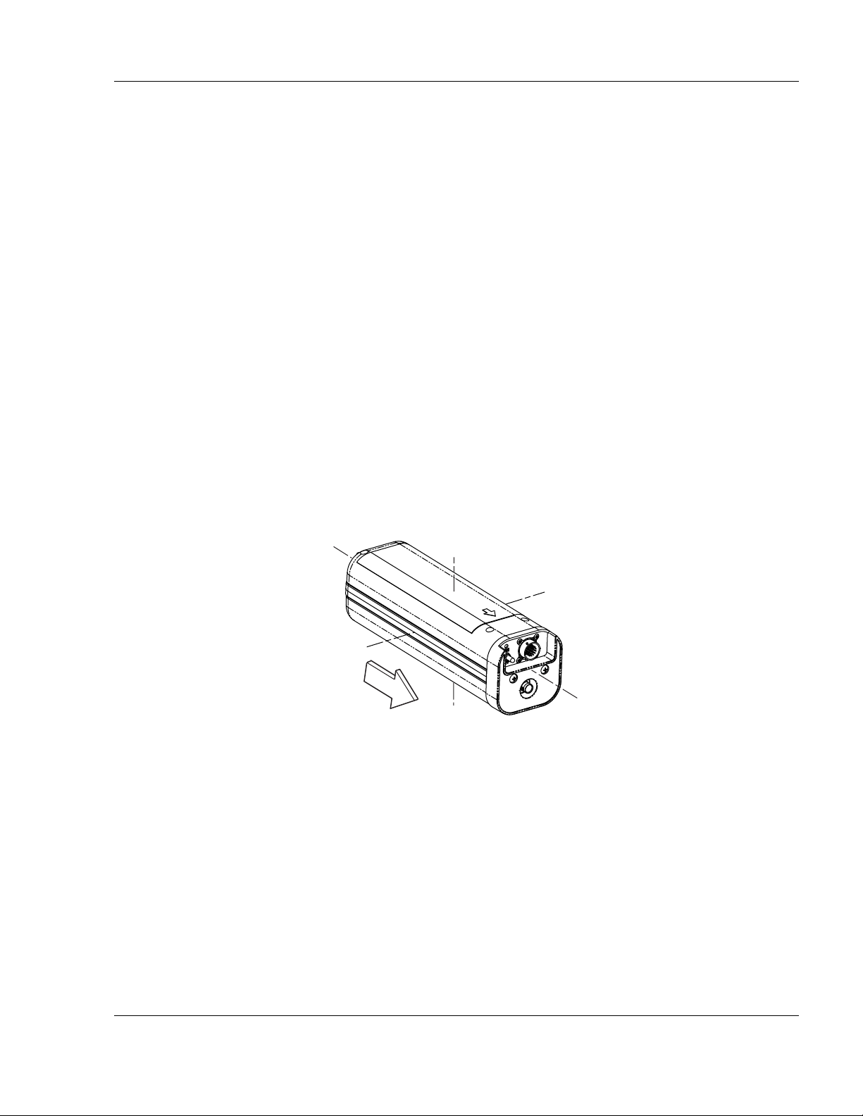
ACR ELECTRONICS, INC / ARTEX PRODUCTS
PROTECTIVE TOP
COVER ASSY
MOUNTING FRAME
CAP ASSY
ELT MAIN
ASSEMBLY
MOUNTING
TRAY ASSY
A
A
CONTROL
SWITCH
INTERFACE
CONNECTOR
ANTENNA BNC
CONNECTOR
LED
ANNUNCIATOR
DESCRIPTION, OPERATION, INSTALLATION AND MAINTENANCE MANUAL
C406-N (453-5060), C406-N HM (453-5061)
(6) After the ELT is activated and the 406 MHz signal is detected by the SAR satellite system and
a position is calculated, the 121.5/243.0 MHz transmissions are used to home in on the crash
site.
NOTE
: Effective February 1, 2009, COSPAS-SARSAT has terminated the satellite processing
of distress signals from 121.5 and 243.0 MHz beacons.
(7) Aircraft communications transceivers are not capable of receiving 406 MHz transmissions;
therefore, the only methods of monitoring the ELT are:
(a) The blinking cockpit remote switch LED,
(b) The buzzer, or
(c) 121.5/243.0 MHz transmissions, which can be monitored using the aircraft
communications transceiver or an AM radio tuned to 121.5 MHz.
SUBTASK 25-62-13-870-002
B. Components
(1) The C406-N Series ELT main assembly is housed in a high impact, fire resistant, polycarbonate
plastic case, which is enclosed in a protective mounting frame assembly made of similar
material. See "Figure 2. C406-N Series ELT and Mounting Frame Assembly".
NOTE
: The ELT main assembly and its mounting frame assembly are capable of
withstanding extremely harsh environments and have been subjected to the rigorous
environmental testing required by COSPAS-SARSAT for certification.
Figure 2. C406-N Series ELT and Mounting Frame Assembly
25-62-13
Page 30 of 109
MAR 1/13
Loading...