

Page 1

SAR AUTOMATIC IDENTIFICATION SYSTEM
User Manual
P/N 2660
Y1-03-0207
ACR Electronics, Inc.
5757 Ravenswood Road
Fort Lauderdale, Fl 33312
+1(954) 981-3333
Fax +1 (954) 983-5087
www.acrelectronics.com
Email: Info@acrelectronics.com
Page 2

=
Please read this first!
Warning:
Although ACR strives for accuracy in all its publications; this material may contain errors or
omissions, and is subject to change without prior notice. ACR shall not be made liable for any
specific, indirect, incidental or consequential damages as a result of its use. ACR components may
only be used in safety of life devices or systems, with the express written approval of ACR, as the
failure of such components could cause the failure of the ACR device or system. If these fail, it is
reasonable to assume that the safety of the user or other persons may be endangered.
User Manual I Y1-03-0207 Rev. A
Page 3

NAUTICAST Transponder
User Manual
Index Page Number
1 STARTING THE NAUTICAST..................................................................................................................................................................4
1.1 Initial Set Up of the NAUTICAST for operation...........................................................................................................................4
1.2 Entering the MMSI and IMO Numbers........................................................................................................................................5
1.3 Entering Ship Settings ................................................................................................................................................................7
1.4 Entering Voyage Related Data ...................................................................................................................................................8
1.5 Service and User Passwords....................................................................................................................................................10
2 NAUTICAST
2.1 NAUTICAST Keyboard .............................................................................................................................................................14
2.2 Explanation of the “Cursor Cross” ............................................................................................................................................14
2.3 Explanation of the Num-Locked and [NUM] Functions.............................................................................................................14
2.4 Explanation of the Soft Keys..................................................................................................................................................... 15
2.5 Safety Keys...............................................................................................................................................................................15
3 NAUTICAST
3.1 Navigation Screen ........................................................................................................................................................................16
3.1.1 Short Header....................................................................................................................................................................18
3.1.2 Other Vessel Details ........................................................................................................................................................ 19
3.2 Menu Structure ......................................................................................................................................................................... 21
3.3 Main Menu ................................................................................................................................................................................22
3.4 Sub-Menus Overview ...............................................................................................................................................................23
3.4.1 Messages.........................................................................................................................................................................23
3.4.2 AIS Status........................................................................................................................................................................23
3.4.3 Voyage Settings – (User Password Protected) ...............................................................................................................24
3.4.4 Ship Settings – (User Password Protected) ....................................................................................................................24
3.4.5 Configuration – (User Password Protected) ....................................................................................................................25
3.4.6 Service Configuration – (Service Password Protected)...................................................................................................25
3.4.7 Display Settings ............................................................................................................................................................... 26
3.4.8 Graphical Display Settings...............................................................................................................................................26
3.5 Sub-Menus Detailed ................................................................................................................................................................. 27
3.5.1 Messages.........................................................................................................................................................................27
3.5.2 AIS Status........................................................................................................................................................................41
3.5.3 Voyage Settings (User Password Protected) ..................................................................................................................46
3.5.4 Ship Settings (User Password Protected) .......................................................................................................................49
3.5.5 Transponder Configuration (User Password Protected)..................................................................................................53
3.5.6 Service Configuration (Service Password Protected).............................................................................
3.5.7 Display Settings ............................................................................................................................................................... 71
3.6 Graphical User Interface (GUI)................................................................................................................................................. 72
3.6.1 Switching between the Views ..........................................................................................................................................72
3.6.2 The Radar View ............................................................................................................................................................... 74
3.6.3 Message and Alarm Handling..........................................................................................................................................82
3.6.4 Configuration of the Graphical Display ............................................................................................................................84
AFETY FUNCTIONS............................................................................................................................................................................. 94
4 S
4.1 MOB Person over Board................................................................................................................................................................ 94
4.2 Activating the SRM Safety Related Message Button..........................................................................................................................96
5 T
ROUBLESHOOTING ...........................................................................................................................................................................101
5.1 Reading and understanding Alarms:..............................................................................................................................................101
5.2 Alarm Codes.............................................................................................................................................................................. 102
5.3 Text Messages.......................................................................................................................................................................... 103
5.4 Restarting the NAUTICAST..........................................................................................................................................................103
6 C
ONTACT AND SUPPORT INFORMATION .............................................................................................................................................. 104
7 A
PPENDIX.......................................................................................................................................................................................... 105
7.1 Explanation of commonly used Abbreviations........................................................................................................................ 105
7.2 Certificates
USER INTERFACE............................................................................................................................................................13
SCREENS .......................................................................................................................................................................16
.........................65
User Manual II Y1-03-0207 Rev. A
Page 4

History of Changes
Date
2006-09-18 1.0 A Released Release New J. Wuenschel
Version Rev. Status
Comments
Responsible
User Manual III Y1-03-0207 Rev. A
Page 5
1 Starting the NAUTICAST
1.1 Initial Set Up of the NAUTICAST for operation
ATTENTION: IMO REGULATIONS MANADATE THAT YOU ENTER THIS INFORMATION.
After installing the antennas and hardware the following User, Voyage related and Ship Settings
data needs to be entered. Upon Start-up (Applying power) enter the following information.
a) Enter MMSI Number - See paragraph 1.2 on entering information.
During the initial boot or after “factory settings” the user is asked to enter a valid MMSI
number. As long as this is not done, the system does not transmit. This appears as Alarm-ID
56 with the text “AIS: ENTER MMSI NUMBER”.
LAT: N/A SOG: N/A 00/00/00
LON: N/A COG: N/A 24:60:60
IntN/A: STOP ! 7A 1T
++++++++++++++++++++++++++++++++++++++++
Time 24:60 00/00
[!] ALARM ID:56
AIS: ENTER MMSI NUMBER
Please press OK to enter MMSI number!
Tx temporary suppressed
++++++++++++++++++++++++++++++++++++++++
b) Enter IMO Number - See paragraph 1.2 on Entering information.
c) Ship Settings Data - After initial entry of the Ship Settings Data any changes in the
information below should be edited accordingly. See Paragraph 1.3 on entering information.
• Enter Call Sign
• Enter Ships Name
• Enter Length of Ship
• Enter Beam of Ship
• Enter Internal GPS antenna Position
• Enter External GPS Antenna Position (If applicable).
• Enter Ship Type
d) Voyage related Data – After initial entry of the Voyage related Data any changes in the
information below should be edited accordingly.
See paragraph 1.4 above on entering information.
• Enter Cargo Type
• Enter Draught
• Enter Destination
• Enter ETA
• Enter Navigation Status.
e) Password – Service and User passwords see section 1.5
User Manual 4 Y1-03-0207 Rev. A
Page 6
o
1
1.2 Enterin g the MMSI and IMO Numbe r s
Select from the Main Menu “Service Configuration” Number 6. Menu is SERVICE password
protected with default password “NAUT”. Enter Service Password and use the up and down arrows
on keypad to select “Change MMSI / IMO” than press M5 “Select” or “by pressing number 3 on the
keypad.
Input your MMSI and IMO number and press Save to store data. Unit will reboot itself after pressing
Save. Continue to 4.2 after reboot.
o
N 1
19' E 0o13' |1>0.01|2>1.30|3>1.80nm
|--------------------------------- | Menu
-----| |
| +- 1. Messages
View | +- 2. AIS Status
| +- 3. Voyage Settings
-----| +- 4. Ship Settings
| +- 5. Transponder Configuration
Msg. | +- 6. Service Configuration
| +- 7. Display Settings
-----|
|
Displ|
---------------------------------------NUM| Select->| | |<-Back
Service Configuration Menu Example:
N 1o21' E 0
|--------------------------------- | 6. Service Configuration
-----| |
| +- 1. Change Service Password
View | +- 2. User Password Settings
| +- 3. Change MMSI / IMO
-----| +- 4. Restore Factory Settings
|
Msg. |
|
-----|
|
Displ|
---------------------------------------NUM| Select->| | |<-Back
4' |1>0.01|2>1.30|3>1.80nm
Note: MMSI and IMO Data input are limited to 9 characters.
User Manual 5 Y1-03-0207 Rev. A
Page 7
N 1o21' E 0o14' |1> N/A|2>0.00|3>0.10nm
********** Change MMSI / IMO ***********
MMSI :1193046
IMO No.:303174162
---------------------------------------NUM| Save | | | Back
User Manual 6 Y1-03-0207 Rev. A
Page 8
1.3 Entering Ship Settings
Select from the Main Menu “Ship Settings” Menu is USER password protected with default password
“NAUT”. Enter Password and use the up and down arrows to edit Ship Settings then press Enter or
the numeric reference on the keypad to select and edit.
Save after editing.
Main Menu Example:
N 1o23' E 0o16' |1>0.01|2>1.30|3>1.80nm
|--------------------------------- | Menu
-----| |
| +- 1. Messages
View | +- 2. AIS Status
| +- 3. Voyage Settings
-----| +- 4. Ship Settings
| +- 5. Transponder Configuration
Msg. | +- 6. Service Configuration
| +- 7. Display Settings
-----|
|
Displ|
---------------------------------------NUM| Select->| | |<-Back
Select Ship Settings and press M5 [Enter]. Enter User Password and Continue.
Ship Settings Menu Example:
o
N 1
19' E 0o12' |1>0.01|2>1.30|3>1.80nm
************ Ship Settings *************
/\ +
CallSign:D11233 / \|
ShipName:ANDREA DORIA | |
Length :220m | A
Beam :43m | x--+
RefPtExt:A200 B20 C10 D33m | | B
RefPtInt:A190 B30 C20 D23m +-C-+D-+
ShipType: Pilot vessel
--------------------------------------- | Save | | | Back
Select and enter Call Sign.
Select and enter Ship Name.
Select and enter Length of Ship.
Select and enter Beam of Ship.
Select and enter Internal and External GPS antenna positions.
Select and enter a default ShipType with the [Left] & [Right] arrows.
User Manual 7 Y1-03-0207 Rev. A
Page 9
Setting the Internal and External GPS Antenna Position.
Note: It is critical for the proper orientation of your ship to other AIS users to enter this data
accurately.
Example: Length of ship = 220m and Beam = 43m.
GPS ANTENNA location on ship (is x in above Menu example) is located 200 meters from bow (A)
and 33 Meters from Starboard side (D).
Note: You can only enter Dimension A and D. B and C are automatically calculated.
You would enter A200D33 (without spaces, no decimals and no commas).
Then Press Save.
The line then should look like the example above for External Reference point.
RefPointExt = A200 B20 C10 D33m (Position of the external GPS antenna)
A = the distance from bow (front) to the antenna.
B= the distance from the antenna to the stern (rear)
C = the distance from the port (left) side to the antenna
D = the distance from the antenna to the starboard (right) side
Enter RefPtInt (location of the internal GPS antenna) in the same way.
Save the new settings by pressing [Save].
Press [Back] return to the Main Menu Screen without saving any changes.
1.4 Entering Voyage Related Data
Select from the Main Menu “Voyage Settings” Menu is USER password protected with default
password “NAUT”. Enter Password and use the up and down arrows to edit Voyage Related data
then press Enter or the numeric reference on the keypad to select and edit.
Save after editing.
Main Menu Example:
N 1o20' E 0o13' |1> N/A|2>0.00|3>0.10nm
|--------------------------------- | Menu
-----| |
| +- 1. Messages
View | +- 2. AIS Status
| +- 3. Voyage Settings
-----| +- 4. Ship Settings
| +- 5. Transponder Configuration
Msg. | +- 6. Service Configuration
| +- 7. Display Settings
-----|
|
Displ|
---------------------------------------NUM|Select->| | |<-Back
User Manual 8 Y1-03-0207 Rev. A
Page 10
Password inquiry Example: The password query field appears. Input password and press M5 [Enter].
N 1o31' E 0o24' |1>0.01|2>1.30|3>1.80nm
----------------------------------------
++++++++++++++++++++++++++++++++++++++++
User password protected!
Please enter user password:
++++++++++++++++++++++++++++++++++++++++
--------------------------------------- | Enter | | | Exit
Scroll to the Voyage Setting Fields with up and down arrows and input your vessel data.
Select a default Cargo Type, Draught, POB (Persons on board), Destination, ETA and Navigation
Status Setting using the [Left] & [Right] arrow keys.
Save the new settings by pressing [Save], and return to the Main Menu Screen by pressing [Exit].
Press [Back] to return to the Main Menu without saving any changes.
Voyage Related Menu Example:
o
N 1
18' E 0o12' |1>0.01|2>1.30|3>1.80nm
*********** Voyage Settings ************
Cargo :<N/A or harmless>
Draught :24.8m
PoB :1
Dest. :CASABLANCA
ETA :10/13 12:31
NavStat.:Engaged in fishing
--------------------------------------- | Save | | | Back
User Manual 9 Y1-03-0207 Rev. A
Page 11
1.5 Service and User Passwords
The Transponder system is equipped with two levels of Password Protection, User and Service
Password.
1) The User Password, which is the lower security level, allows access to all menus except Menu 6:
Service Configuration which is protected by the Service Password.
2) The Service Password is required in order to enter the Service Configuration Menu. This is a
higher security level that can not be accessed with the User Password and therefore ensures that
the Service Configuration is protected, and limited to authorized service personnel.
The master of the vessel has to ensure that only authorized persons are allowed to make changes to
the Service Configuration and ensures that the newly reset password is stored very carefully, as it
can not be reset from the default “NAUT” a second time.
WARNING: a master key is not available and the unit would have to be returned to a service center
to correct for a lost Service password.
The User Password can be reset in the service configuration menu by entering the Service
Configuration menu and creating a new password.
Changing the Service Password
Select “Service Configuration” from the Main Menu with the cursor button [Up] & [Down] or press
Number 6 on the keyboard.
The password query field appears. Input default Service Password “NAUT” and press M5 [Enter].
N 1o24' E 0o17' |1>0.10|2>1.30|3>1.80nm
----------------------------------------
++++++++++++++++++++++++++++++++++++++++
Service password protected!
Please enter service password:
++++++++++++++++++++++++++++++++++++++++
--------------------------------------- | Enter | | | Exit
Select Submenu 1 “Change Service Password” with cursor button [Up] & [Down] by pressing Nr. 1
on the keyboard.
User Manual 10 Y1-03-0207 Rev. A
Page 12
Service Menu Example:
N 1o21' E 0o14' |1>0.01|2>1.30|3>1.80nm
|--------------------------------- | 6. Service Configuration
-----| |
| +- 1. Change Service Password
View | +- 2. User Password Settings
| +- 3. Change MMSI / IMO
-----| +- 4. Restore Factory Settings
|
Msg. |
|
-----|
|
Displ|
---------------------------------------NUM| Select->| | |<-Back
Service Password Menu Example:
N 1o25' E 0o18' |1>0.10|2>1.30|3>1.80nm
******* Change Service Password ********
Enter new password :
Repeat new password:
{Length: 4..8 characters}
--------------------------------------- | Save | | | Back
Enter the new Password: Then push Enter (M5).
Repeat the new Password: Then Push Enter (M5).
A minimum of 4, a maximum of 8 characters are allowed. Should the new password include
numbers, use the shift key to generate them.
Press Save to store the change.
Changing the User Password
Select Submenu 2 “User Password Settings” with cursor button [Up] & [Down] or by pressing Nr. 2
on the keyboard.
User Manual 11 Y1-03-0207 Rev. A
Page 13
o
21' E 0o14' |1>0.01|2>1.30|3>1.80nm
N 1
|--------------------------------- | 6. Service Configuration
-----| |
| +- 1. Change Service Password
View | +- 2. User Password Settings
| +- 3. Change MMSI / IMO
-----| +- 4. Restore Factory Settings
|
Msg. |
|
-----|
|
Displ|
---------------------------------------NUM| Select->| | |<-Back
Select Submenu 1 “Change User Password” with cursor button [Up] & [Down] or by pressing Nr. 1
on the keyboard.
N 1o21' E 0o14' |1>0.01|2>1.30|3>1.80nm
|--------------------------------- | 6-2. User Password Settings
-----| |
| +- 1. Change User Password
View | +- 2. Change Password Protection
|
-----|
|
Msg. |
|
-----|
|
Displ|
---------------------------------------NUM| Select->| | |<-Back
Enter the new Password:
Repeat the new Password:
A minimum of 4, a maximum of 8 characters are allowed. Should the new password include
numbers, use the shift key to generate them.
N 1o25' E 0o18' |1>0.10|2>1.30|3>1.80nm
******* Change User Password ***********
Enter new password :
Repeat new password:
{Length: 4..8 characters}
--------------------------------------- | Save | | | Back
Press Save to store the changes.
User Manual 12 Y1-03-0207 Rev. A
Page 14
_
S
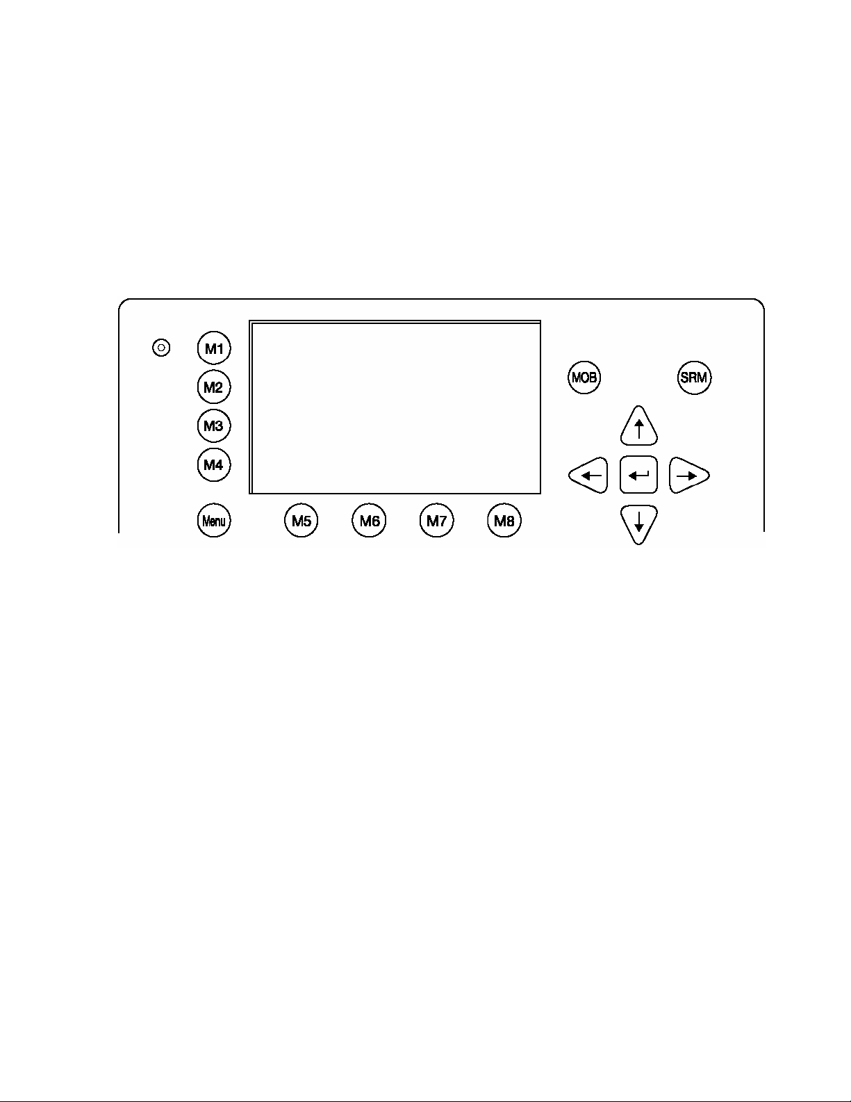
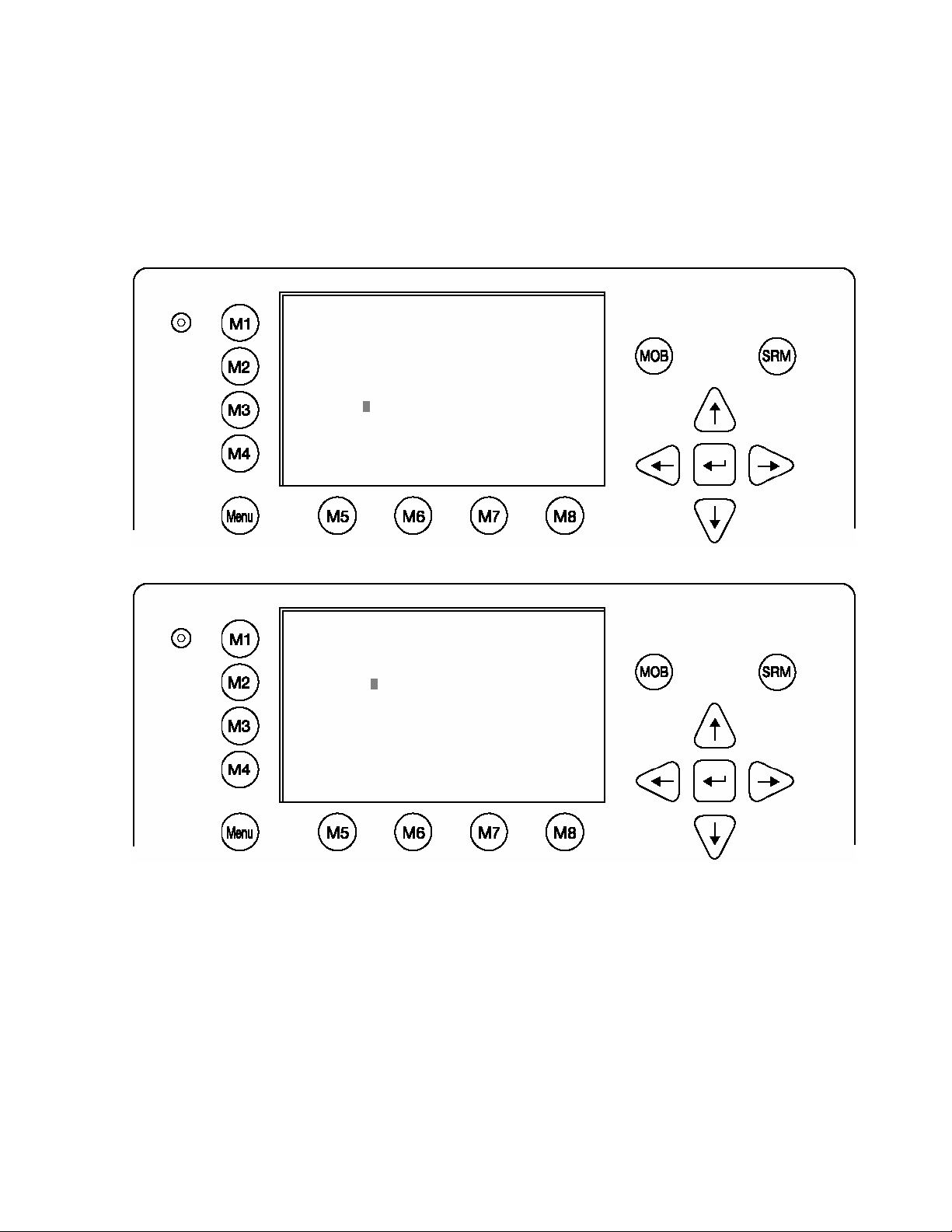
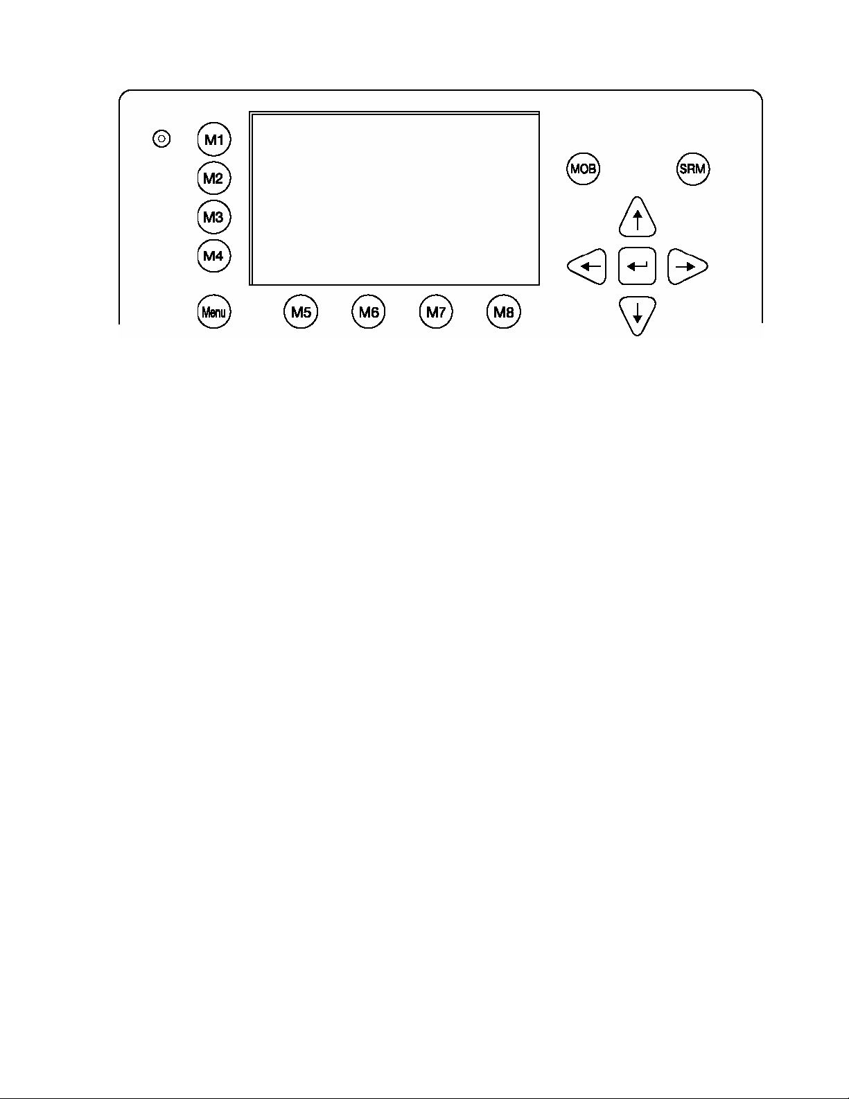
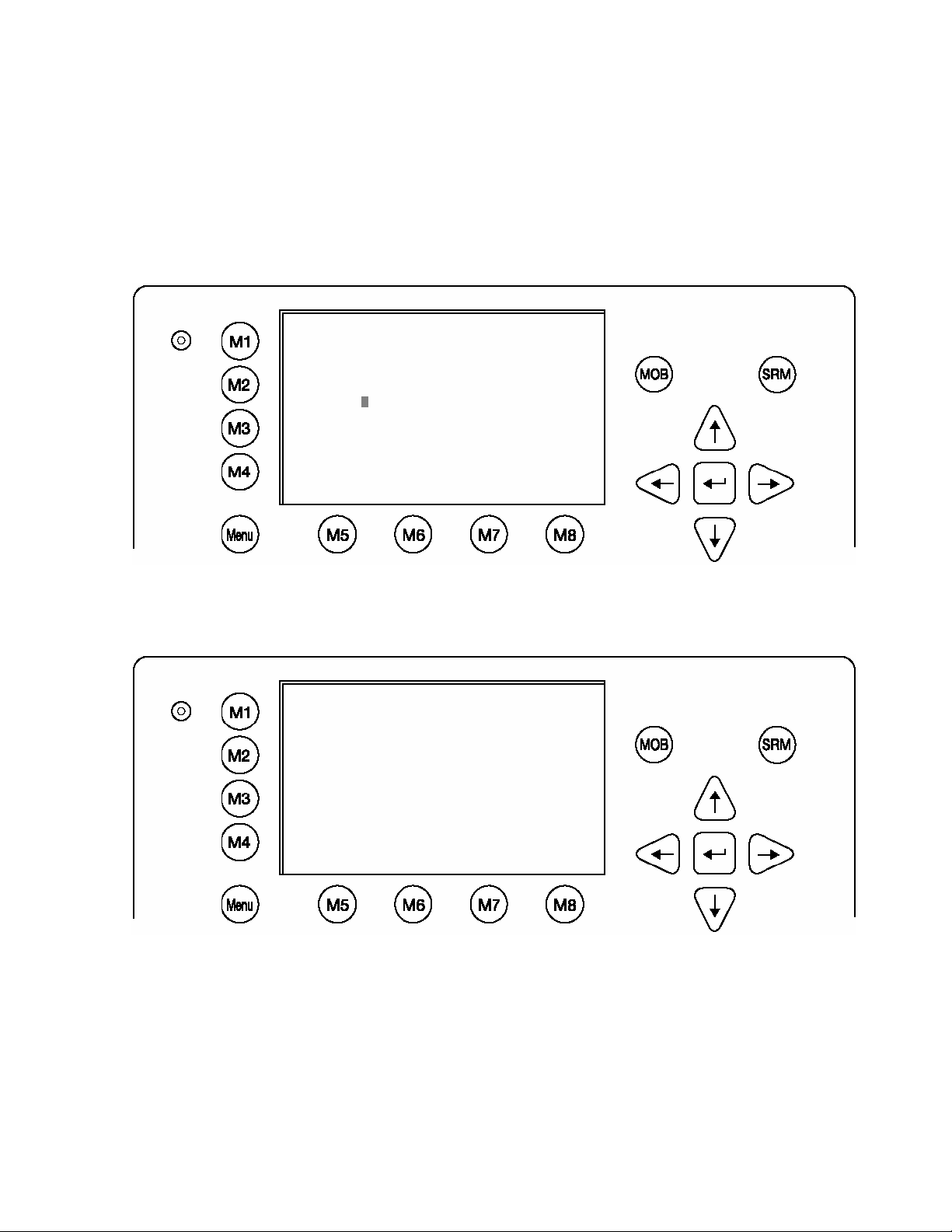
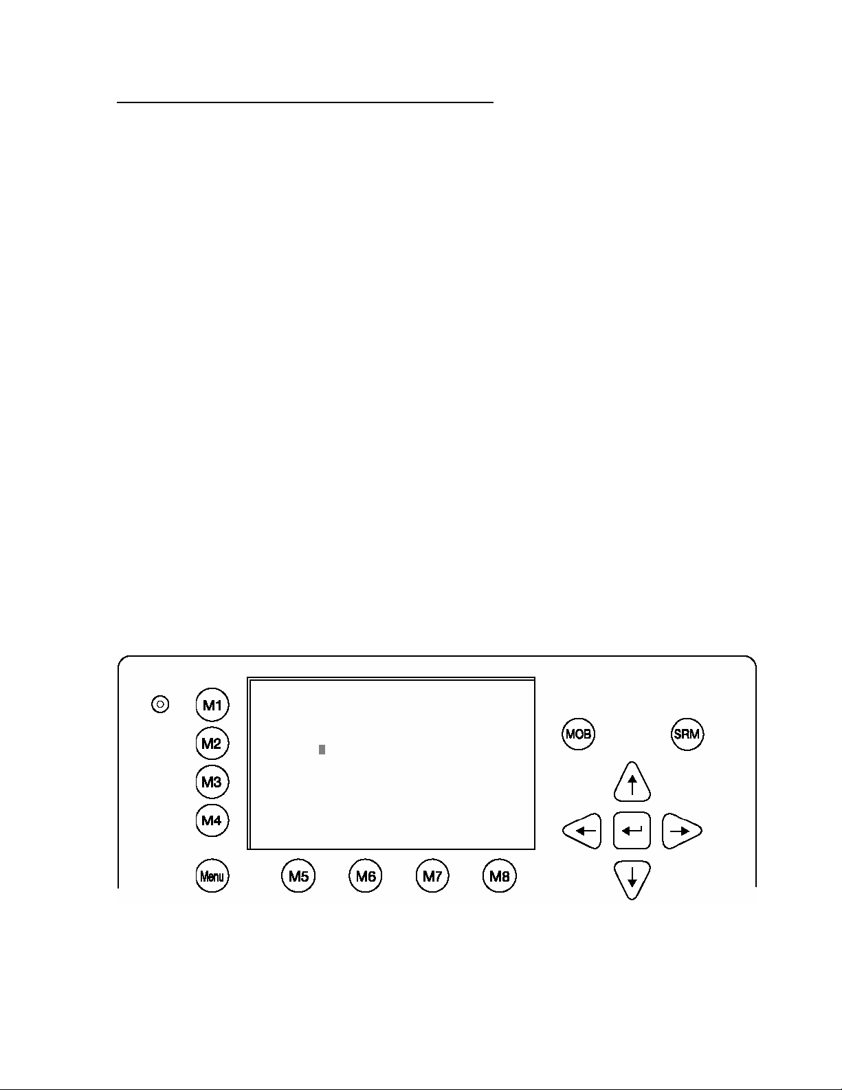
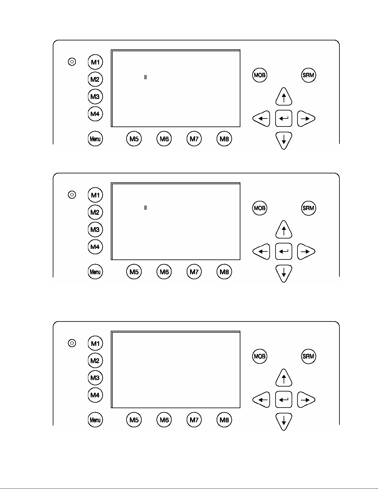
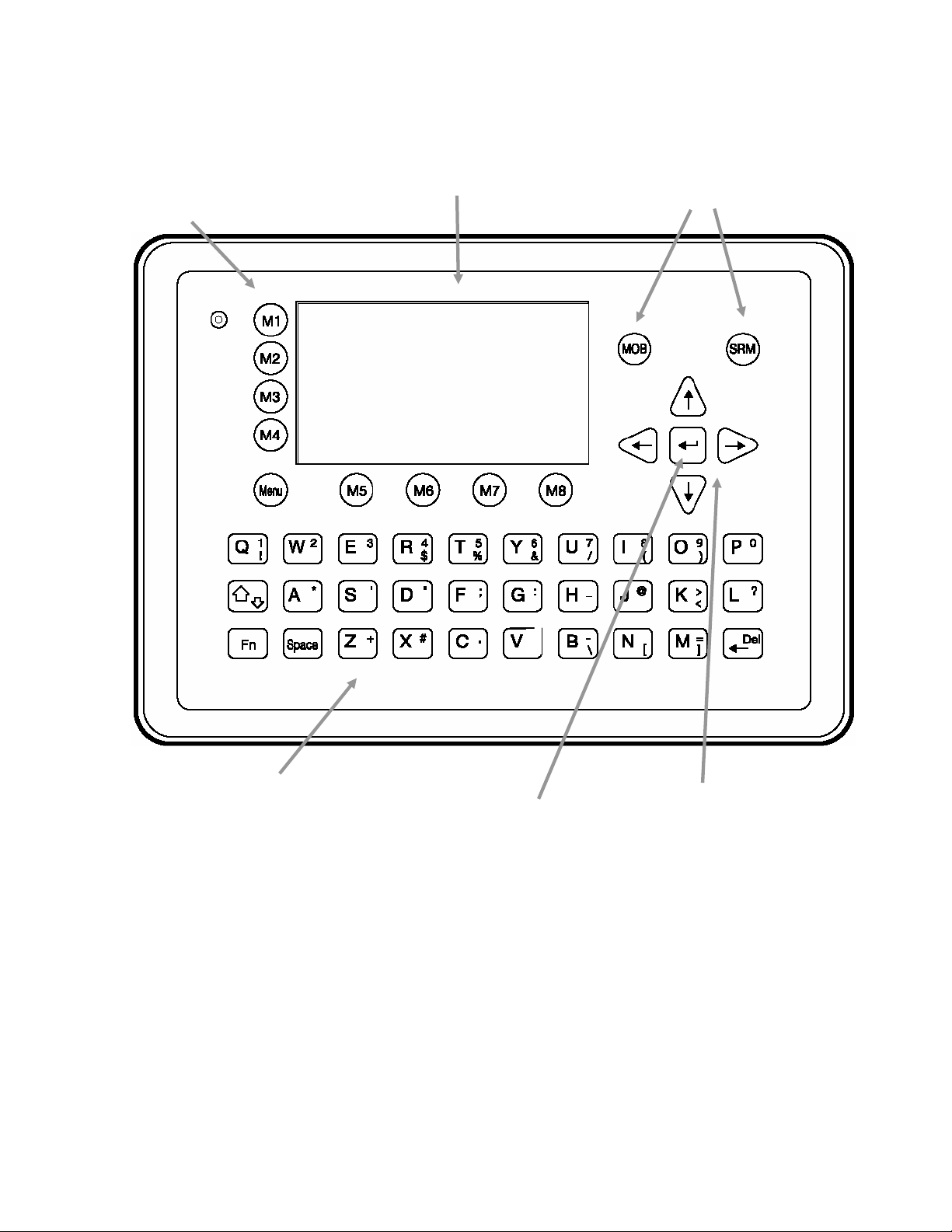
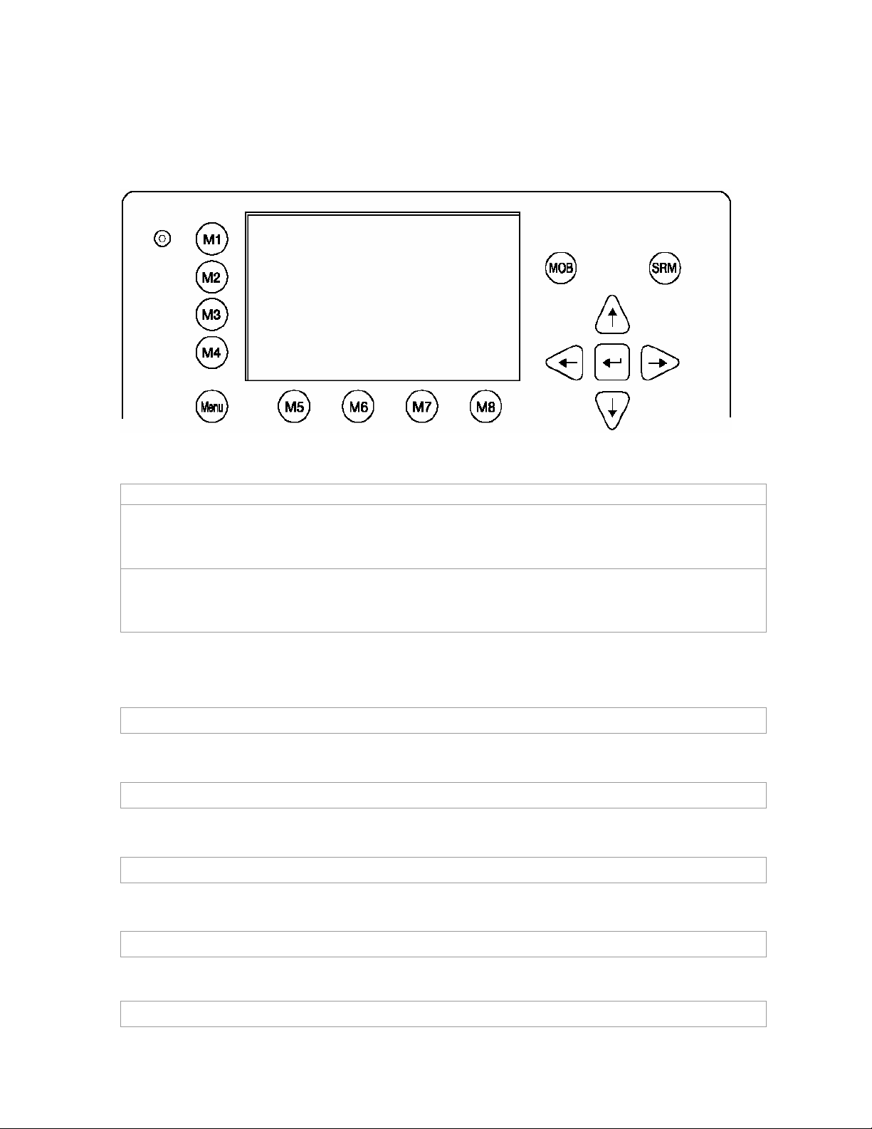
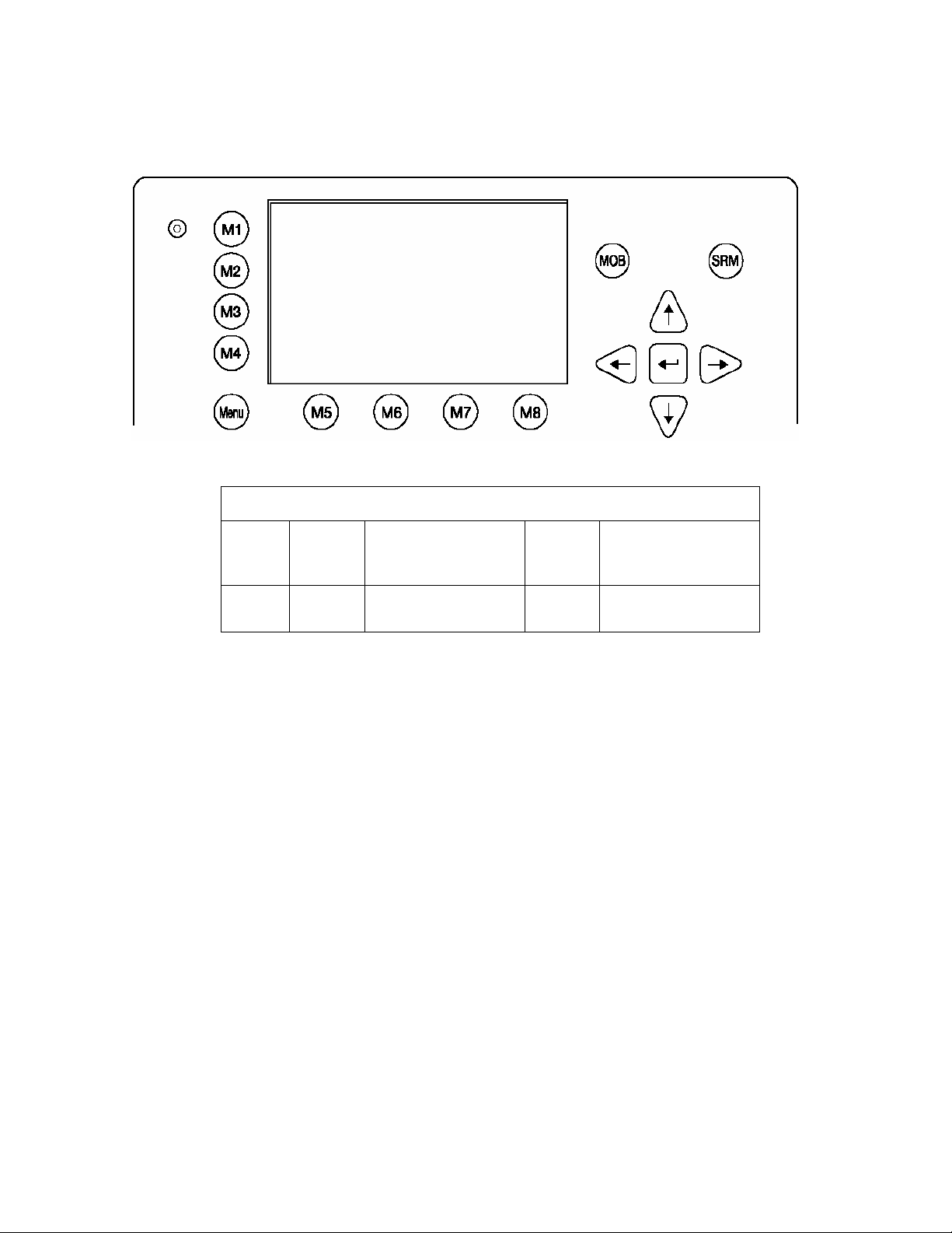
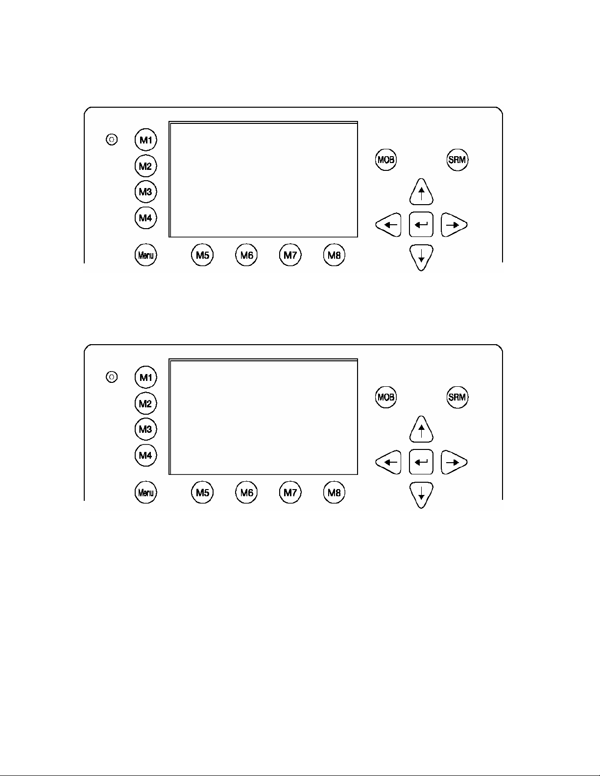
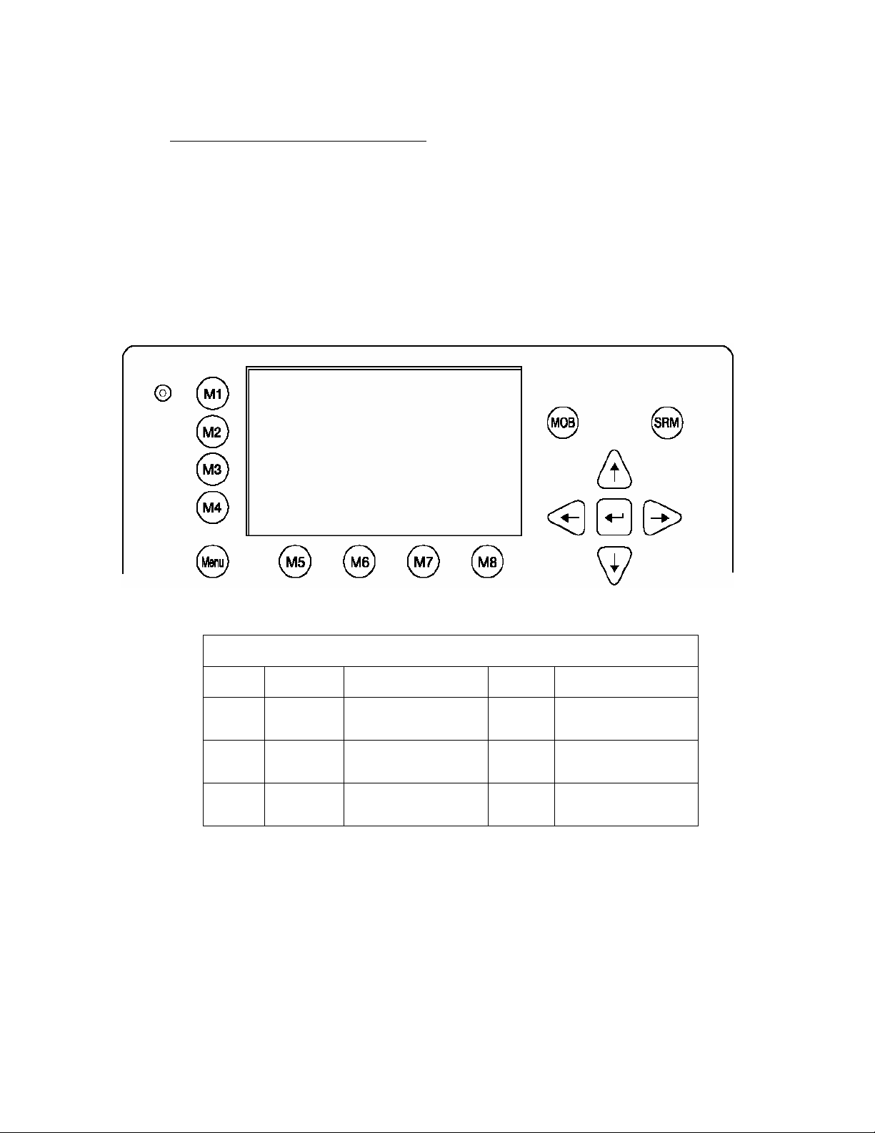
2 NAUTICAST User Interface
Soft Keys [M1] – [M8]
Navigation Screen
Header (max. 3 lines)
________________
Navigation Screen or
(Content 13 lines)
MENU
Display
tructure
Safety Keys
.
o
Keyboard
Enter Key
Curser
Cross
User Manual 13 Y1-03-0207 Rev. A
Page 15
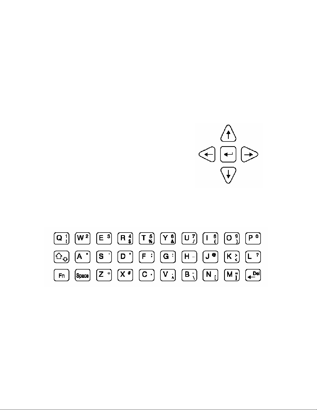
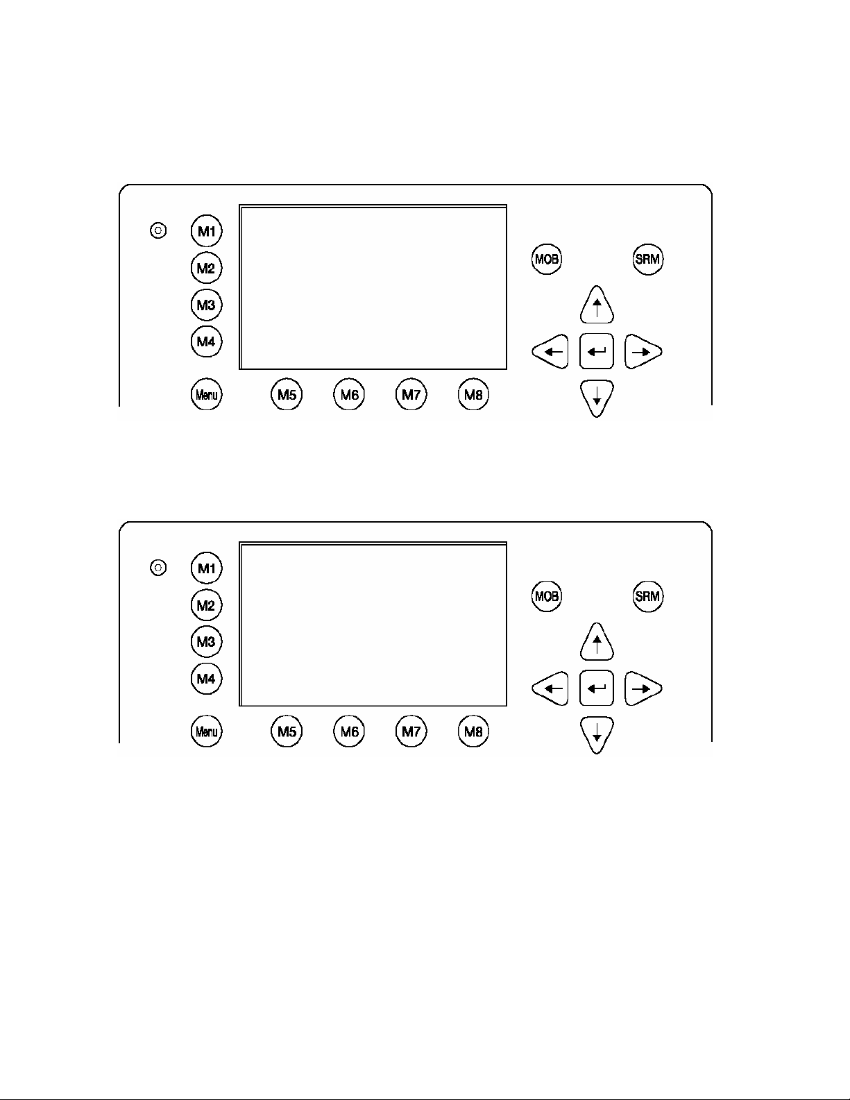
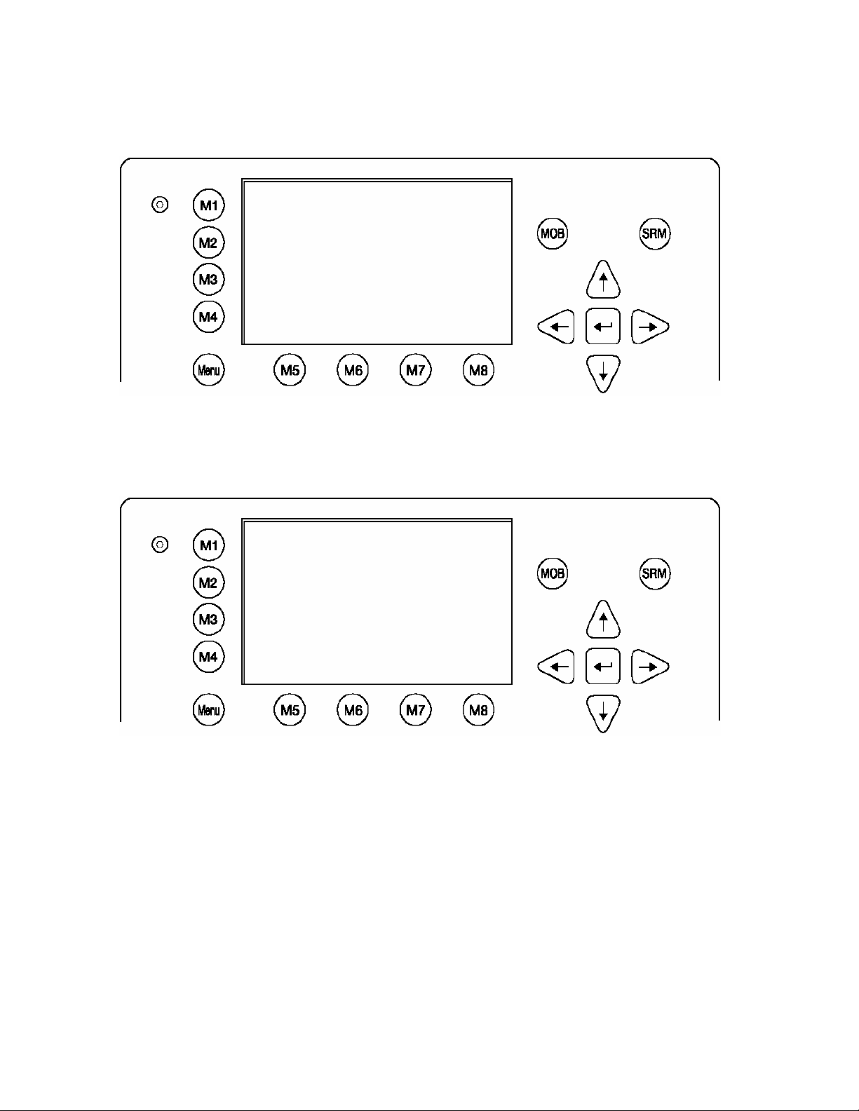
2.1 NAUTICAST Keyboard
The NAUTICAST is fitted with a full alphanumeric keyboard, with the following functions:
By pressing any key on the keyboard the letters are addressed.
Number symbols and special characters are addressed by holding down the
shift [×] key and simultaneously pressing the chosen key.
The characters ($; %; &; /; (; ); <;
o
; \ ; [; ]; ) can be reached by holding down the Function [Fn] key
and pressing the chosen key.
2.2 Explanation of the “Cursor Cross”
The Cursor Cross allows navigation within the current
screen [Up] [Down] [Left] [Right].
In addition to the actually displayed [Enter]
button, the
center of the cursor cross always has the Enter functionality.
2.3 Explanation of the Num-Locked and [NUM] Functions
The NUM-Locked function is enabled after pressing the Function [Fn] Key and the Shift [×] Key.
It is possible to disable the Num-Lock Function by pressing the Shift [×] Key.
Tip: The NAUTICAST automatically changes the keys “Q” through to “P” to numerical input when the
current application requires numbers, rather than letters to be input. This feature is enabled when
[NUM] appears on the bottom left hand side of the screen.
User Manual 14 Y1-03-0207 Rev. A
Page 16

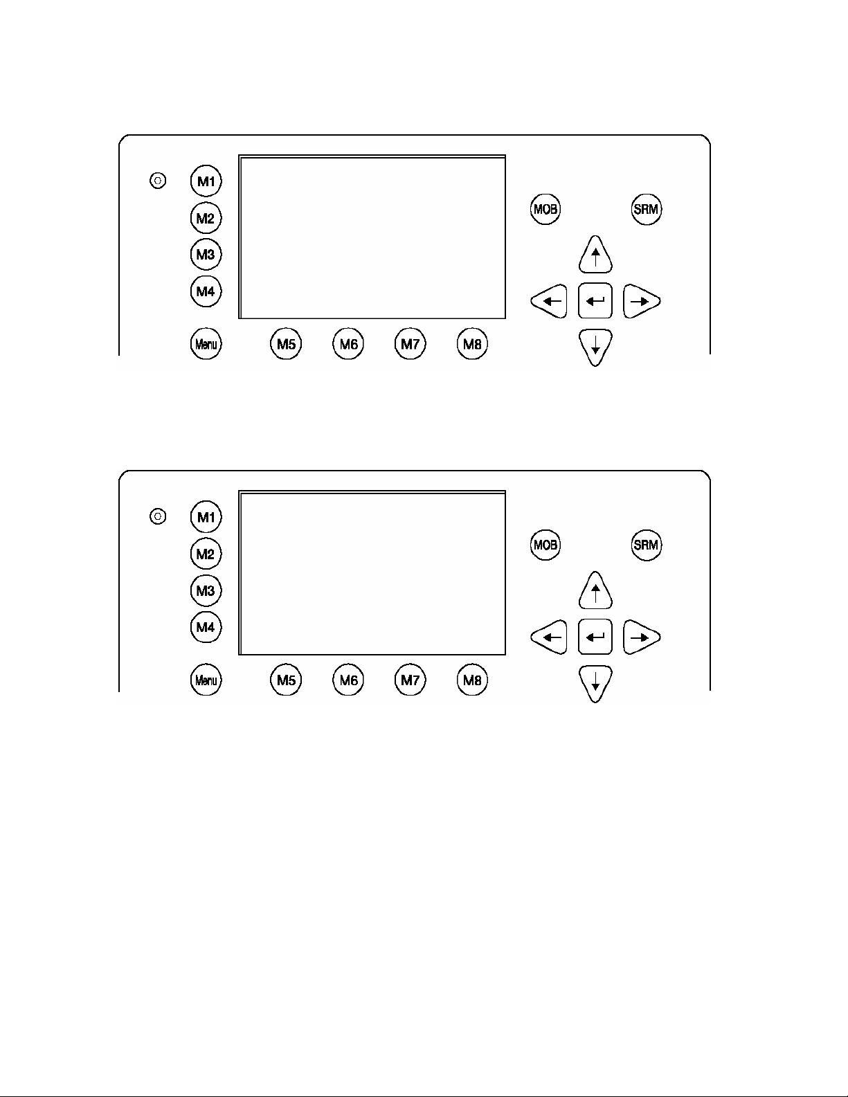
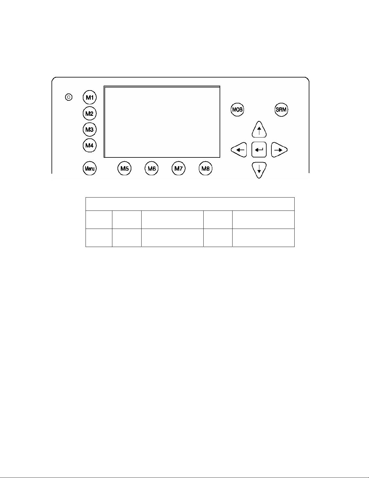
2.4 Explanation of the Soft Keys
The Soft Keys are divided into vertical static keys [M1-M4] and horizontal dynamic keys [M5-M8],
which differ in function according to the current application.
Soft Key Definition
filter option on AIS targets in graphical view
[M1]
• FA (hides received Class A targets)
• FB (hides received Class B targets)
[M2]
Display Modes
This Soft Key allows toggling between the different Display Modes.
Safety Message
[M3]:
This Soft Key allows direct Message Writing. Either broadcast or addressed messages
can be sent in this mode. Pending alarms could be accessed by this Soft Key
Display Settings - Brightness and Contrast Regulator
[M4]:
This Soft Key allows the Display Settings to be changed between Daytime,
and Nighttime Modes.
[Menu]: Go to Main Menu or return to the Navigation View Screen.
[M5] – [M8]: These Soft Keys are described in individual screens
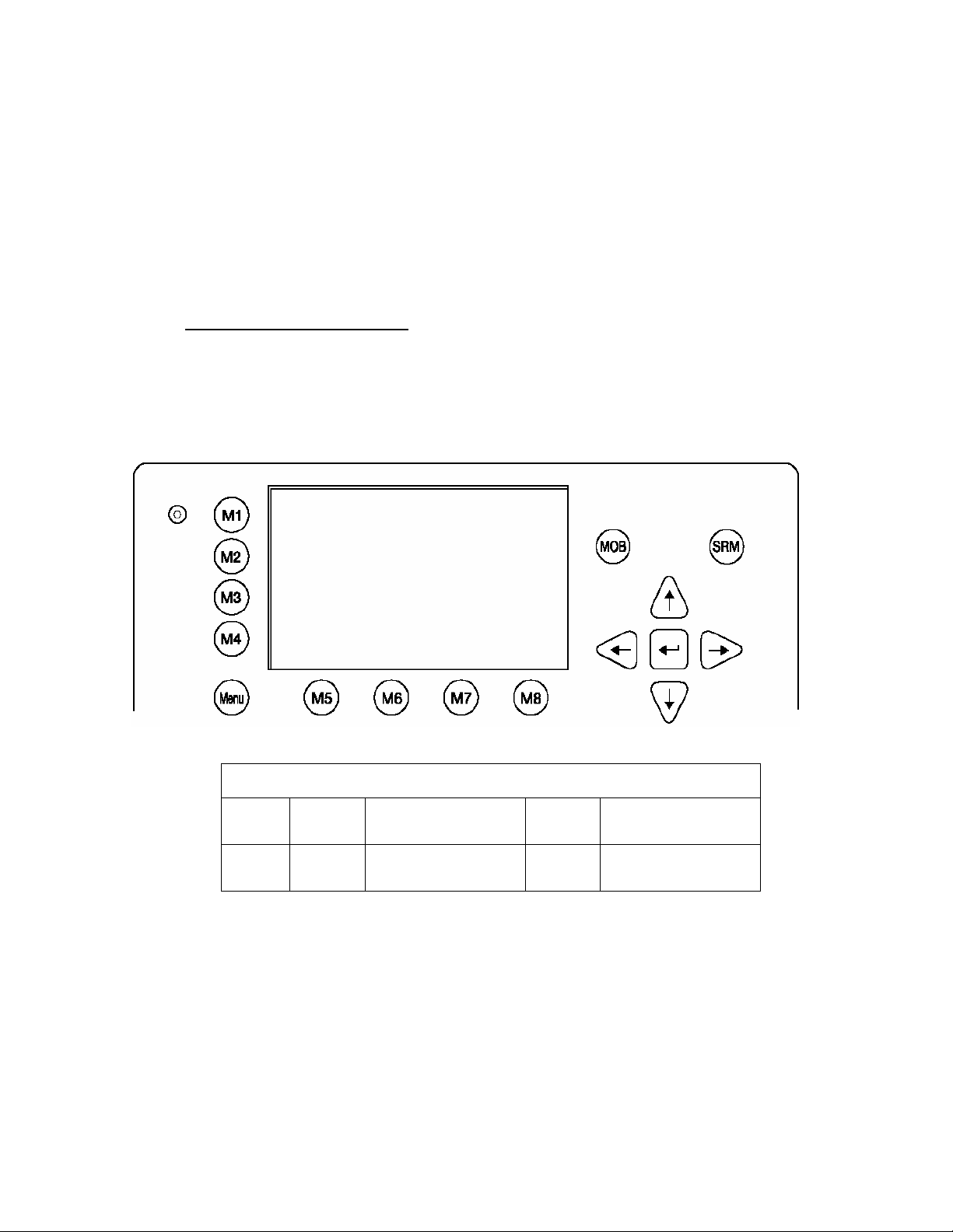
2.5 Safety Keys
The NAUTICAST is fitted with Safety Keys, which allow the user to automatically send urgent
messages without the necessity of navigating the Menus.
The MOB Button sends out precise position of an MOB incident to Addressed
[MOB]
Vessels, therefore allowing the message to be sent to a vessel closest to
accident location.
[SRM]
The SRM Button sends out emergency Broadcast Safety Related Messages to
all ships in the Vessel Listing.
Note:
For detailed description of the Safety Functions see Chapter 4.
User Manual 15 Y1-03-0207 Rev. A
Page 17
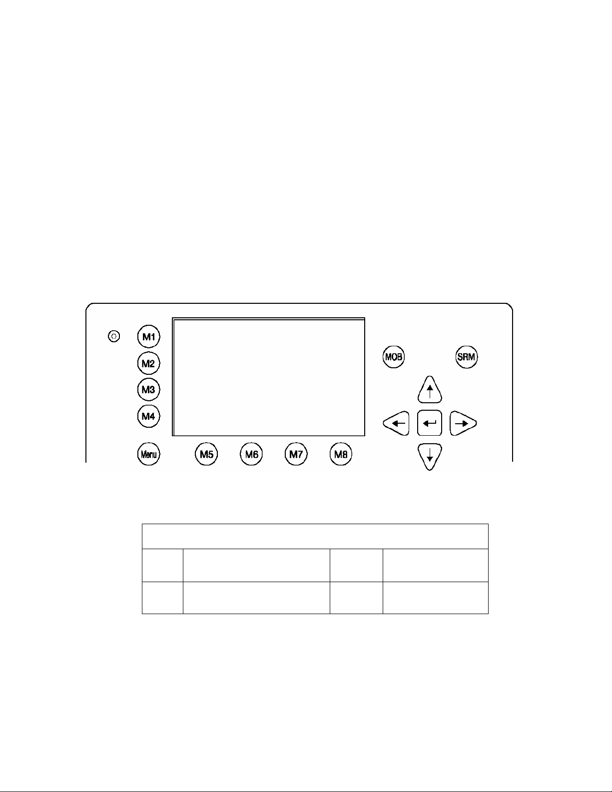
3
3 NAUTICAST Screens
The advanced version of the
Navigation Screen - Standard screen, automatically visible
Menu Structure - Visible after pressing the [Menu] Soft Key
Graphical User Interface - The Graphical User Interface is visible after pressing the [M2] Soft
3.1 Navigation Screen
This screen provides the user with Navigation Data from their own vessel and lists all other vessels
within receiving range. This screen automatically appears after a period of 60 seconds of user
inactivity on the Transponder.
NAUTICAST offers three display modes:
Key (new mode)
LAT:N 1°27.845'ExtSOG:34.6kn 05/26/06
LON:E 0°21.289'ExtCOG:173.0° 10:52:26
IntGPS: 3D A/ ExtHDT:222° Reg6 !
001/021..ShipName....RNG.BRG..SOG..COG..
DOREEN [Cl-A] N/A 120 22.2 301.5
FINE EAGLE [Cl-A] 0.00 N/A 13.1 359.9
SYLVAEPSILON [Cl-A] 0.10 23 32.1 203.2
ESSOTOKYO [Cl-A] 0.43 99 10.0 120.3
KATHARGO [Cl-B] 0.59 342 21.2 50.0
SANEI [Cl-A] 0.80 272 32.1 270.1
KATOO [Cl-A] 1.00 321 21.2 200.8
ID=002319999_[Base] 1.34 277 0.0 0.0
MINILOG [Cl-A] 1.96 201 21.7 102.2
ALIBRAHIMYA [Cl-A] 2.66 340 22.1 30.3
EWALD M [Cl-A] 2.75 121 N/A N/A
ID=231919191 [SAR ] 3.36 66 24.1 2.9>
A 2T
Dynamic Keys: Navigation Screen
[M5]
[Enter]
Select desired vessel
for Vessel Details
Select desired vessel for
Vessel Details
[Up] /
[Down]
[Left] /
[Right]
Scroll Vessel Listing
Pages
Scroll Vessel Listing
Pages
Lines 1 – 3 of the Navigation Screen represent your own vessels data (display Latitude and
Longitude, Speed Over Ground, Course Over Ground, Heading, Date and the UTC).
After line 4, all data refers to other vessels within receiving range.
User Manual 16 Y1-03-0207 Rev. A
Page 18

Own Vessel Data
LAT:N 1°27.845'ExtSOG:34.6kn 05/26/06
LON:E 0°21.289'IntCOG:173 .0 ° 10:52:26
LAT: Latitude
LON: Longitude
Date:
The actual UTC - date (MM.DD.YY) and time (hh.mm.ss) are displayed on the top
right hand corner of this view.
IntGPS: 3D A/ ExtHDT:222° Reg6
IntGPS Indicates normal or differential mode of GPS position.
2D or 3D: Indicates the precision of the GPS result.
Indicates the used position source:
intGPS. = internal GNSS receiver
extGPS = external GNSS receiver (sensors)
A/B: (A or B) Indicates the last transmitting channel in use.
ExtHDT True Heading
Reg:
Indicates the actual region of own vessel’s position. If no region number is displayed,
then the vessel is traveling on high sea and is outside a predefined region.
Message (SRM) Indication
o
LAT:N 1
27.845'ExtSOG:34.6kn *3S
Queued safety related messages, e.g. *3S are displayed in the date field (instead of the date) – in
the above example 3 Safety Related (3S) Messages are queued, and await viewing and handling
(acknowledgement or reply) in the Message Inbox History.
Alarm (ALR) and Text (TXT) Indication
IntGPS: 3D /B Reg6 ! 3A 2T
Queued alarms or messages, e.g. ! 3A 2T are displayed in the 3rd line – in the above example
3 (3A) Alarms and 2 (2T) Text Messages are in queue, and await viewing and handling
(acknowledgement and reaction).
User Manual 17 Y1-03-0207 Rev. A
Page 19

Other Vessel Data
001/021..S
001/021
HIPNAME....RNG.BRG..SOG..COG..
(E.g: Vessel 01 of 021) current or selected Vessel/ Total number of Vessels (max.
256 Vessels)
Name of the Ship and AIS – Type:
Cl-A: SOLAS Class-A Ship
ShipName:
Cl-B: Leisure Craft
Base: Base station
SAR : Search and Rescue Aircraft
Vessel Range
RNG
Note: The vessel closest to own ship, or where position data is unknown (N/A), is
listed first.
BRG Vessel True Bearing
SOG Speed Over Ground
COG Course Over Ground
A maximum of 12 vessels are displayed on the screen. If more than 12 vessels are currently being
received, the symbol [>] on the right bottom appears, indicating that there are further vessels to be
seen in the Vessel Listing. By pressing the [Right] key, it is possible to scroll to the next page for
further Vessel Listing, by pressing the [Left], the user scrolls back to the previous page.
Further details on any individual vessel can be obtained by scrolling down and selecting the desired
vessel by pressing [Enter]. A full explanation of the Vessel Details is given in the following section.
3.1.1 Short Header
A constant overview of the most important AIS navigation details, including own position and
distance of the three closest vessels is always displayed the first line. This information appears in
every Submenu and is called the “Short Header”.
o
21 E 0o14' |1>0.10|2>1.30|3>1.8 0nm
N 1
Own Vessel Position: N 1o21' E 0o14'
1> Closest vessel situated 0.10 nm away
2> Second closest vessel situated 1.30nm away
3> Third closest vessel situated 1.80nm away
User Manual 18 Y1-03-0207 Rev. A
Page 20
3.1.2 Other Vessel Details
This screen shows the Dynamic, Voyage and Vessel Related Data, which is currently being
transmitted by a previously selected vessel.
N 1o21' E 0o14' |1>0,10|2>1.30|3>1.80nm
Time 2:07 ------------------ POS:001/021
LAT : S 74-50'23 LON : W 9-34'19
Heading :77
IMO No. :90733283 MMSI:5004
ShipName:DOREEN CS:DORET6W
ShipType:Passenger ship
Length :310m Beam:73m
RefPoint:A190 B120 C10 D>=63m
Cargo :N/A or harmless
Draught :3.3m
Dest. :HAWAI
ETA :10/15 12:31
NavStat.:Moored
EPFDType:GPS
PosAcc :High<10m DTE :Available
o
ROT :-0.2o/min l
Current Time and Selected Vessel Number in Vessel Listing:
Time 2:07 ---------------- POS: 0001/0021
Time:
The period of time which has elapsed since the last update is shown in minutes and seconds.
The update rate differs according to the respective vessels speed.
POS:
Indicates the number of the selected vessel (e.g. vessel 02 of 21) from the Vessel Listing and the
total number of vessels being received.
Position of the selected vessel:
LAT :S 74-50'23" LON :W 9-34'19"
Heading and Rotation of the selected vessel:
Heading :77
o
ROT :-0.2o/min l
IMO-Number and MMSI of the selected vessel:
IMO No. : 90733283 MMSI: 5004
Name and CallSign of the selected vessel:
ShipName:DOREEN CS:DORET6W
Vessel Type
Passenger ship
User Manual 19 Y1-03-0207 Rev. A
Page 21

Length and Beam of the selected vessel:
Length:310m Beam:73m
Reference Point (in meters):
This information indicates the Reference Point of the used GPS Antenna onboard the vessel.
RefPoint:A190 B120 C10 D<63m
A: 190m
B: 120m
C: 10m
D: <63m (means more than 63m in the case of a very large vessel)
Vessels Cargo:
Indicates the type of cargo on board.
N/A or harmless
Further Vessel Details:
Draught : 3.3m
Dest : HAWAII
ETA : 10/15 12:31
NavSt : Moored
Information on the vessel’s Equipment Position Finding Device:
EPFDType: GPS
Position Accuracy and Data Terminal Equipment (DTE):
PosAcc :High <10m
DTE :Available
This information indicates that the vessels Transponder is connected with a user interface and can
show AIS Data. This function basically ensures that the current Transponder being used is fitted with
a display and can therefore send and receive messages. As the NAUTICAST is fitted with an
integrated display unit, it will always show “DTE: Available”.
User Manual 20 Y1-03-0207 Rev. A
Page 22

3.2 Menu Structure
To call up the Main Menu, press the [Menu] button once, and all Submenus are displayed. The
cursor position indicates the selected submenu.
Menu navigation is achieved by pressing the [Up] or [Down] keys to select, and then by pressing
[Enter] to confirm the desired Submenu selection.
To escape from any Submenu and returning to the Navigation Screen, press the [M2] button at any
time.
The own vessel’s current Navigation Information is continuously displayed on the first line. It
contains the own position and the first three vessels, which are located within closest range of the
own ship.
Tip: Fast Menu Selection is achieved by simply pressing the desired Submenu Number on the
keyboard.
User Manual 21 Y1-03-0207 Rev. A
Page 23
3.3 Main Menu
N 1o46' E 0o39' |1>0.10|2>1.30|3>1.80nm
|--------------------------------- | Menu
-----| |
| +- 1. Messages
View | +- 2. AIS Status
| +- 3. Voyage Settings
-----| +- 4. Ship Settings
| +- 5. Transponder Configuration
Msg. | +- 6. Service Configuration
| +- 7. Display Settings
-----| +- 8. Graphical Display Settings
|
Displ|
---------------------------------------NUM |Select->| | <-Back
Dynamic Keys: Main Menu Screen
[M5] [Select]
[M8] [Back]
Select chosen
Submenu
Return to Navigation
Screen
[Enter]
or
[Right]
[Up] /
[Down]
Confirm Submenu
Selection
Navigate Submenu
for selection
Note:
The Navigation Screen automatically appears after some seconds of user inactivity on the
Transponder, or immediately by pressing the [Menu] button in the Main Menu.
User Manual 22 Y1-03-0207 Rev. A
Page 24
3.4 Sub-Menus Overview
3.4.1 Messages
N 1o19' E 0o12' |1>0.10|2>1.30|3>1.80nm
| 1. Messages
-----| |
| +- 1. Write Addressed SRM
View | +- 2. Write Broadcast SRM
| +- 3. Inbox History
-----| +- 4. Inbox SRM
| +- 5. Inbox ALR (valid only)
Msg. | +- 6. Inbox LRI
|
-----|
|
Displ|
---------------------------------------NUM|Select->| | | <-Back
3.4.2 AIS Status
N 1o18' E 0o12' |1> N/A|2>0.00|3>0.10nm
|--------------------------------- | 2. AIS Status
-----| |
| +- 1. State / Conditions
View | +- 2. Own Ship Data
| +- 3. Own VHF Status
-----| +- 4. Alarm Status
| +- 5. TXT Status
Msg. | +- 6. Version Info
| +- 7. Security Log
-----|
|
Displ|
---------------------------------------NUM|Select->| | |<-Back
User Manual 23 Y1-03-0207 Rev. A
Page 25
3.4.3 Voyage Settings – (User Password Protected)
N 1o20' E 0o14' |1>0.10|2>1.30|3>1.80nm
*********** Voyage Settings ************
Cargo :<N/A or harmless>
Draught :24.8m
PoB :1
Dest. :CASABLANCA
ETA :10/13 12:31
NavStat.: Engaged in fishing
--------------------------------------- | Save | | | Back
3.4.4 Ship Settings – (User Password Protected)
N 1o20' E 0o14' |1>0.10|2>1.30|3>1.80nm
************ Ship Settings *************
/\ +
CallSign:D11233 / \|
ShipName:ANDREA DORIA | |
Length :220m | A
Beam :43m | x--+
RefPtExt:A200 B20 C10 D33m | | B
RefPtInt:A190 B30 C20 D23m +-C-+D-+
ShipType: Pilot vessel
--------------------------------------- | Save | | | Back
User Manual 24 Y1-03-0207 Rev. A
Page 26
o
3.4.5 Configuration – (User Password Protected)
N 1o21' E 0o14' |1>0.10|2>1.30|3>1.80nm
|--------------------------------- | 5. Transponder Configuration
-----| |
| +- 1. Change User Password
View | +- 2. Region Settings
| +- 3. Alarm Settings
-----| +- 4. Interrogation Settings
| +- 5. Sensor Settings
Msg. | +- 6. GPS Settings
|
-----|
|
Displ|
---------------------------------------NUM| Select->| | | <-Back
3.4.6 Service Configuration – (Service Password Protected)
N 1
21' E 0o14' |1>0.10|2>1.30|3>1.80nm
|--------------------------------- | 6. Service Configuration
-----| |
| +- 1. Change Service Password
View | +- 2. User Password Settings
| +- 3. Change MMSI / IMO
-----| +- 4. Restore Factory Settings
|
Msg. |
|
-----|
|
Displ|
---------------------------------------NUM| Select->| | |<-Back
User Manual 25 Y1-03-0207 Rev. A
Page 27
3.4.7 Display Settings
N 1o21' E 0o15' |1>0.10|2>1.30|3>1.80nm
*********** Display Settings ***********
Mode
|
+-[*] Day Min Max
| +---- Brightness:<9> [*********]
| +---- Contrast : 6 [****** ]
|
|
+-[ ] Night Min Max
+---- Brightness: 3 [*** ]
+---- Contrast : 2 [** ]
---------------------------------------NUM|DayNight| | | Back
3.4.8 Graphical Display Settings
N 1o46' E 0o39' |1>0.10|2>1.30|3>1.80nm
|--------------------------------- | 8 Graphical Display Settings
-----| |
| +- 1. Fairway View Scale
View | +- 2. Fairway View Symbols
| +- 3. Radar View Symbols
-----| +- 4. Other graphical Settings
|
Msg. |
|
-----|
|
Displ|
---------------------------------------NUM |Select->| | <-Back
User Manual 26 Y1-03-0207 Rev. A
Page 28
3.5 Sub-Menus Detailed
3.5.1 Messages
N 1o26' E 0o19' |1>0.10|2>1.30|3>1.80nm
|--------------------------------- | 1. Messages
-----| |
| +- 1. Write Addressed SRM
View | +- 2. Write Broadcast SRM
| +- 3. Inbox History
-----| +- 4. Inbox SRM
| +- 5. Inbox ALR (valid only)
Msg. | +- 6. Inbox LRI
|
-----|
|
Displ|
---------------------------------------NUM| Select->| | | <-Back
Dynamic Keys: Messages
[M5] [Select]
[M8] [Back]
Select chosen
Submenu
Return to Main Menu
Screen
[Enter]
[Up] /
[Down]
Confirm Message
Submenu Selection
Navigate Submenu
for Selection
Writing Messages:
This screen provides a means to write and send messages.
It is possible to select between an Addressed Message to a single selected vessel, and a Broadcast
Message, which is sent out to all vessels in the current Vessel Listing.
Message Inboxes:
The Inbox History gives an overview of all incoming messages. The Inboxes are further divided into
3 sections, allowing the user to see, and act upon specific Message Types.
1.3 Inbox History: Overview of all Messages, Alarms and LRI Interrogations
1.4 Inbox SRM: Listing all Safety Related Messages (SRM)
1.5 Inbox ALR: Listing of all valid Alarms (ALR)
1.6 Inbox LRI: Listing of all Long Range Interrogations (LRI)
User Manual 27 Y1-03-0207 Rev. A
Page 29
Message Storage Capacity:
The Inbox History has the capacity to store a total of 60 messages. The older messages are
automatically deleted, when the respective Inbox has reached its maximum storage capacity.
Message Type: Maximum Storage Capacity:
Addressed or Broadcast Messages (SRM): Latest 30 Messages stored
Alarms (ALR): Latest 20 stored
Long Range Interrogation (LRI): Latest 10 stored
a) Writing an Addressed Message
To write a Safety Related Message first select an addressee from the Vessel Listing. This is possible
by using the cursor buttons [Up] and [Down], and confirming the selection with [Enter] or [Select].
Tip: For fast Vessel Selection press the Vessel Number on the keyboard and the selected vessel is
immediately displayed.
N 1o26' E 0o20' |1>0.10|2>1.30|3>1.80nm
************ Write Message *************
..ShipName......Dist..SOG..COG..CallSign
1>DOREEN-------> N/A 22.2 301.5 DORET6W
2>FINE EAGLE--->0.00 13.1 359.9 OEX1538
3>SYLVAEPSILON->0.10 32.1 203.2 ND4RX
4>ESSOTOKYO---->0.43 10.0 120.3 ZA9A
5>OLYMPIAHIGHWA>0.59 21.2 50.0 3FSH4
6>SANEI-------->0.80 32.1 270.1 YJQX9
7>KATOO-------->1.00 21.2 200.8 A4F317
8>OLYMPIA PALAC>1.34 [BASESTAT] 4DSW
9>MINILOG------>1.96 21.7 102.2 FOR6
10>ALIBRAHIMYA->2.66 22.1 30.3 DEZ42
11>TITANIC----->2.75 N/A N/A FSG >
---------------------------------------NUM| Select | | | Back
Dynamic Keys: Messages
[M5] [Select]
[M8] [Back]
Write Message to
Selected Vessel
Return to Messages
Menu
[Enter]
Write Message to
Selected Vessel
User Manual 28 Y1-03-0207 Rev. A
Page 30
b) Using the NAUTICAST Message Editor
After selecting a vessel, the Message Editor is automatically displayed.
Messages containing a maximum of 156 characters are allowed. Longer texts require a second
message. After text input completion, transmission to the selected addressee is facilitated by
pressing the [Send] button. The [<Back] button leads to the Message Editor for writing a second
message to the same addressee. A second activation of the [<Back] button leads to the Vessel
Listing and allows selection of another addressee.
It is possible to select the desired channel by pressing the [<Channel>] buttons.
The default setting for Addressed Messages is (auto) in contrast to Broadcasted Messages, where
the default setting is set at Channels A+B (AIS1 + AIS2).
N 1o20' E 0o13' |1>0.10|2>1.30|3>1.80nm
************ Write Message *************
Addressed SRM 129
SendTo:5004 (DOREEN)
Text:TEXT INPUT IS POSSIBLE HERE
--------------------------------------- auto/ A / B /A+B
Channel: [*]/[ ]/[ ]/[ ]
--------------------------------------- | Send |<Channel |Channel> | Back
Dynamic Keys: Addressed Message Editor
[M5] [Send] Send Message [Enter] Send Message
[M6] [Channel]
[M7] [Channel]
[M8] [Back]
Select Transmission
Channel
Select Transmission
Channel
Return to Vessel
Listing
User Manual 29 Y1-03-0207 Rev. A
Page 31

o
c) Confirmation of Sent Addressed Message
The confirmation screen shows the successful message transmission and indicates which channels
(AIS1 or AIS2) were used.
Successful Message Transmission on Channel AIS1:
LAT:N 1o18.963'ExtSOG:34.6kn 05/21/2006
LON:E 0
Ships:21 /B IntGPS: 3D Region6
++++++++++++++++++++++++++++++++++++++++
Transmission Status
[+] AIS1:OK, acknowledgement received
[-] AIS2:
++++++++++++++++++++++++++++++++++++++++
--------------------------------------- | | Send To | |<-Back
o
12.408'IntCOG:173.0 09:11:08
In some cases, the recipient’s Transponder may not be able to receive the message immediately –
due to Transponder in-operation. In this case, the confirmation of the send message arrives later,
upon Transponder re-operation.
Successful Message Confirmation (late reply):
LAT:N 1
LON:E 0
Ships:21 /B IntGPS: 3D Region6
++++++++++++++++++++++++++++++++++++++++
Transmission Status
[?] AIS1:Late reception of an ack.
[ ] AIS2:
++++++++++++++++++++++++++++++++++++++++
--------------------------------------- | | Send To | |<-Back
18.992'ExtSOG:34.6kn 05/21/2006
o
12.436'IntCOG:173.0 12:55:06
User Manual 30 Y1-03-0207 Rev. A
Page 32

It is possible, that the recipient’s Transponder could not receive the message at all, and in this case
the following screen is displayed. It is then recommended to resend the message.
Unsuccessful Message Confirmation (no acknowledgement)
o
19' E 0o12' |1>0.10|2>1.30|3>1.80nm
N 1
----------------------------------------
++++++++++++++++++++++++++++++++++++++++
Transmission Status
[ ] AIS1:
[-] AIS2: Sent, but no acknowledgement
++++++++++++++++++++++++++++++++++++++++
User Manual 31 Y1-03-0207 Rev. A
Page 33

d) Writing a Broadcast Message
Upon selection of Write Broadcast SRM in the Message Menu, the Message Editor appears.
Messages containing a maximum of 161 characters are allowed. Longer texts require a second
message. When the text input has been completed, transmission to all vessels within receiving
range is possible by pressing the
[Send] button. The [<Back] button leads to the Message Editor.
It is possible to select the desired channel by pressing the [<Channel>] buttons. The default Settings
for Broadcasted Message Setting is A+B (AIS1 and AIS2).
N 1o18' E 0o12' |1>0.10|2>1.30|3>1.80nm
************ Write Message *************
Broadcast SRM 111
Text:MILITARY EXCERSISE IN AREA, KEEP AW
AY. SHIP MASTER
--------------------------------------- auto/ A / B /A+B
Channel: [ ]/[ ]/[ ]/[*]
----------------------------------------
Dynamic Keys: Broadcast Message Editor
[M5] [Send] Send Message [Enter] Send Message
[M6] /
[M7]
[Channel]
[M8] [Back]
Select Transmission
Channel (A+B is
default)
Return to Messages
Menu
User Manual 32 Y1-03-0207 Rev. A
Page 34

-
B
o
e) Confirmation of Broadcast Sent Message
This Confirmation Screen shows that the message was successfully transmitted on the Broadcast
Setting. By pressing [Back] the user automatically returns to the Message Editor for further
Messaging. The [SendTo]
returns the user to the Vessel Listing, with the option of further Message
Writing to individual vessels.
o
N 1
19' E 0o13' |1>0.10|2>1.30|3>1.80nm
---------------------------------------++++++++++++++++++++++++++++++++++++++++
Broadcast Transmission Status
[+] OK, broadcast successful
++++++++++++++++++++++++++++++++++++++++
--------------------------------------- | | Send To | | <
ack
In the case of failed transmission, the following screen appears. In this case, it is recommended to
retransmit the Broadcast Message.
19' E 0o13' |1>0.10|2>1.30|3>1.80nm
N 1
----------------------------------------
++++++++++++++++++++++++++++++++++++++++
Broadcast Transmission Status
[-] Message could not be sent
++++++++++++++++++++++++++++++++++++++++
--------------------------------------- | | Send To | |<-Back
User Manual 33 Y1-03-0207 Rev. A
Page 35

f) Long Range Interrogation
Mobile, and shore-based stations have the ability to interrogate vessels and make requests for
information over the “Long Range Interface”. The interrogated vessel can either reply in automatic,
or in manual mode. The interrogation request is displayed in both modes.
The arrival of a Long Range Interrogation Request is indicated by:
1L on the top right hand corner of the Navigation Screen. The LRI automatically arrives in the
Message Inbox LRI and can be handled from there.
LAT:N 1o20.256'ExtSOG:34.6kn * 1L
LON:E 0
IntGPS: 3D ExtHDT:222
001/021..ShipName....RNG.BRG..SOG..COG..
1>DOREEN-----------> N/A 120 22.2 301.5
2>FINE EAGLE------->0.00 N/A 13.1 359.9
3>SYLVAEPSILON----->0.10 23 32.1 203.2
4>ESSOTOKYO-------->0.43 99 10.0 120.3
5>OLYMPIAHIGHWAY FE>0.59 342 21.2 50.0
6>SANEI------------>0.80 272 32.1 270.1
7>KATOO------------>1.00 321 21.2 200.8
8>OLYMPIA PALACE--->1.34 277 [BASESTAT]
9>MINILOG---------->1.96 201 21.7 102.2
10>ALIBRAHIMYA----->2.66 340 22.1 30.3
11>TITANIC--------->2.75 121 N/A N/A
12>BWRTZ123-------->3.36 66 24.1 2.9>
o
13.700'IntCOG:173.0o 07:44:49
o
Reg6 SRM /B
Handling a Long Range Interrogation (LRI)
Default Settings for LRI Requests:
Automatic Mode: The LRI is automatically dealt with and own vessel data is sent.
Manual Mode: The LRI needs to be manually handled.
Note:
The data which may be interrogated via the Long Range Interface can be configured in Menu 5:
Configuration, Submenu 5: Interrogation Settings.
User Manual 34 Y1-03-0207 Rev. A
Page 36

An LRI has arrived;
The NAUTICAST Settings are configured to Automatic Mode:
N 1o20' E 0o13' |1>0.10|2>1.30| * 1L
************** Inbox LRI ***************
LRI *07:44 5004
07:44 11/28 ------------------ POS:01/01
LRI 5004
(automatic mode)
Please confirm with OK!
--------------------------------------- | OK | | Reply | Back >
Dynamic Keys: LRI in the Inbox History (automatic mode)
[M5] [OK]
Confirms that LRI
has been seen
[M8] [Back]
Send Addressed
[M7] [Reply]
Message to LRI
sender
Return to
Message Menu
Upon activation of the [OK] button, the user confirms that he has been notified of a current
Transponder system interrogation. This information is useful, as it prevents unknown interrogation
from taking place when the transponder is set in automatic mode.
Upon pressing the [Reply] button, user returns to the Message Editor from where it is possible to
send an addressed message to the LRI sender.
N 1o20' E 0o13' 1>0.10|2>0.00|3>0.10nm
************** Inbox LRI ***************
LRI 07:44 5004
TEXT TO LRI SENDER CAN BE INPUT HERE
07:44 11/28 ------------------ POS:01/01
LRI 5004
ACK
--------------------------------------- | | | Reply | Back
User Manual 35 Y1-03-0207 Rev. A
Page 37

An LRI has arrived; the NAUTICAST Settings are configured to Manual Mode:
The LRI therefore needs to be manually handled (accepted or rejected)
N 1o20' E 0o14' ||1>0.10|2>1.30| * 1L
************** Inbox LRI ***************
LRI *07:49 5004
LRI 07:44 5004
07:49 11/28 ------------------ POS:01/02
LRI 5004
(manual mode)
Please acknowledge with OK/Reject!
--------------------------------------- | OK | Reject | Reply | Back
Dynamic Keys: LRI in the Inbox History (manual mode)
Send Addressed
[M5] [OK]
Accept LRI’s
[M7] [Reply]
Message to LRI
Sender
[M6] [Reject]
Reject LRI’s
[M8] [Back]
Return to
Messages Menu
User Manual 36 Y1-03-0207 Rev. A
Page 38

g) Inbox History
The Inbox History provides a means to reading incoming messages and alarms. The messages are
listed in chronological sequence. The message type (SRM, ALR or LRI), Status, Time, Message
Text Preview and MMSI Number of sender are shown in this overview screen.
To select a message navigate with the cursor [Up] or [Down] – the selected message text is
displayed in the text field. The [Back] button takes the user to Messages Menu.
N 1o19' E 0o13'|1>0.10|2>1.30| *1S1A
************ Inbox History *************
ASRM 13:43 PIRATE ATTACK! 5264
ASRM*13:42 LOST COOK! 5004
ALR 13:40 external EPFS lost 25
ALR!*13:38 general failure 6
ALR! 13:39 no sensor pos in use26
13:43 11/21 ------------------ POS:01/05
AddressedSRM 5264
Text: PIRATE ATTACK!
ACK
--------------------------------------- | | | | Back
Inbox History: Overview of Received Messages and Alarms
Message Types: Description
ASRM Addressed Safety Related Message
BSRM Broadcast Safety Related Message
ALR Alarms (Details – see Alarm Types)
LRI Long Range Interrogation
Message Status:
* Marks a new, unacknowledged message or alarm
! Marks a valid alarm requiring action
[ ] Marks a revoked alarm (no longer active)
Abbreviation, which is displayed on bottom right hand corner
ACK (Acknowledged)
and signifies that selected message or alarm, has been
previously acknowledged.
User Manual 37 Y1-03-0207 Rev. A
Page 39

Inbox History: Message and Alarm Types and Status Definition:
N 1o19' E 0o13' |1>0.10|2>1.30 * 1S1A
************ Inbox History *************
ASRM 13:43 PIRATE ATTACK! 5264
ASRM*13:42 HIGH WINDS IN AREA! 5004
ALR 13:40 external EPFS lost 25
ALR!*13:38 general failure 6
ALR! 13:39 no sensor pos in use26
13:43 11/21 ------------------ POS:01/05
AddressedSRM 5264
Text: PIRATE ATTACK!
ACK
--------------------------------------- | | | | Back
ASRM 13:43 PIRATE ATTACK! 5264
Addressed Safety Related Message, acknowledged by recipient, arrived at 13:43, with text
“Pirate Attack”, from vessel with MMSI 5264
ASRM*13:42 HIGH WINDS IN AREA! 5004
Addressed Safety Related Message, unacknowledged by recipient, arrived at 13:42, with text
“High winds in area!” from vessel with MMSI number 5004
ALR 13:40 external EPFS lost 25
Alarm, no longer active (revoked) with ID Number 25 (see Alarm Types), revoked at 13:40 with
text “external EPFS lost”
ALR!*13:38 general failure 6
Alarm, new and valid with ID Number 6, not yet revoked at 13:38 with text “general failure”.
ALR! 13:39 no sensor pos in use26
Alarm, old, still valid and requiring attention, with ID Number 2, arrived at 13:39 with text “no
sensor position in use”
13:43 11/21 ------------------ POS:01/05
AddressedSRM 5264
Text: PIRATE ATTACK!
The text of the selected message (in this case Message POS 01/05) is shown in the text field.
User Manual 38 Y1-03-0207 Rev. A
Page 40

ASRM – Reading Incoming Addressed Safety Related Messages:
N 1o26' E 0o20' |1>0.10|2>1.30|3>1.80nm
************** Inbox SRM ***************
ASRM*17:39 CAPTAIN IS LOST 5004
ASRM 16:26 ROUGH SEA! 5022
17:39 11/26 ------------------ POS:01/02
AddressedSRM 5004
Text:CAPTAIN IS LOST
Channel:AIS1 ACK
--------------------------------------- | | Reply | | Back
ASRM: Information
Time 17:39
Date 11/26 (mm.dd)
POS 01/02 (Message 01 of 02)
Message Type AddressedSRM
Status * (not acknowledged)
MMSI of Sender
Channel
ACK
5004
Incoming AIS Channel
Message not yet acknowledged
User Manual 39 Y1-03-0207 Rev. A
Page 41

ALR – Reading Incoming Alarms:
N 1o27' E 0o21' |1>0.10|2>1.30|3>1.80nm
************** Inbox ALR ***************
ALR! 17:36 no valid COG information 30
17:36 11/26 ------------------ POS:01/01
[!] ALARM ID:30
no valid COG information
ACK
--------------------------------------- | | | | Back
ALR: Information
Time 17:36
Date 11/26 (mm.dd)
POS 01/1
Message Type ALARM
Alarm ID 30
Status [!] Valid alarm, requiring action
User Manual 40 Y1-03-0207 Rev. A
Page 42

3.5.2 AIS Status
The AIS Status Menu provides a variety of information concerning own vessel settings, as well as
the current AIS status of the other vessels, which are displayed in the Vessel Listing.
Version Info provides details of the actual software release currently installed. Security Log traces
the downtimes of the Transponder, to ensure those periods of down time when the transponder is
out of order or lacking electricity can be traced.
N 1o19' E 0o12' |1> N/A|2>0.00|3>0.10nm
|--------------------------------- | Menu
-----| |
| +- 1. Messages
View | +- 2. AIS Status
| +- 3. Voyage Settings
-----| +- 4. Ship Settings
| +- 5. Transponder Configuration
Msg. | +- 6. Service Configuration
| +- 7. Display Settings
-----|
|
Displ|
---------------------------------------NUM|Select->| | |<-Back
Dynamic Keys: AIS Status
[M5] [Select]
[M8] [Back]
Confirm Submenu
Selection
Return to Main
Menu
[Enter]
Confirm Submenu
Selection
User Manual 41 Y1-03-0207 Rev. A
Page 43

a) State / Conditions
This screen provides a means to viewing the current AIS status of all vessels within receiving range.
The information reported is own vessel’s last AIS contact with the other vessel in the listing (Time),
the Transponder mode (Mod.), the synchronization status (Syn.) and the total number of vessels
being received by each vessel in the listing (RXVe). The vessel’s (MMSI) number is also shown on
the right hand side of the screen.
N 1o22' E 0o15' |1>0.10|2>1.30|3>1.80nm
********** State / Conditions ***** AIS1
ShipName......Time.Mod.Syn.RXVe..MMSI...
DOREEN 2:07 AU I 1 5004
FINE EAGLE 4:51 AU I 11 5008
SYLVAEPSILON 2:54 AU I 1 5264
ESSOTOKYO 2:11 AU D 2 5776
OLYMPIAHIGHWA 6:44 ?? D 1 354503000
SANEI 5:39 AU I 6 776840000
KATOO 2:58 AU D 3 203375830
OLYMPIA PALAC 6:01 AS D 2 241455470
MINILOG 4:42 AS D 7 234712450
ALIBRAHIMYA 7:40 AS B 3 232834560
TITANIC 0:57 AS I 2 419245790>
--------------------------------------- | | | | Back
Mod.: AIS Transmission Mode
AU Autonomous
AS Assigned
IN Interrogation/Polled Mode
?? Unknown
Used Channel AIS1, AIS2
Syn.: (UTC source)
D UTC direct
I UTC indirect
B Sync to Base
A Sync to mobile with the most received stations
(Semaphore)
RXVe: Total number of all received stations by the
individual vessel.
MMSI: MMSI number of the individual vessel.
User Manual 42 Y1-03-0207 Rev. A
Page 44

b) Own Ship Data
This screen shows own Ship, and Voyage Data, which was previously input in Menu 3: Ship Settings
and Menu 4: Voyage Settings.
N 1o26' E 0o19' |1>0.10|2>1.30|3>1.80nm
Time 0:08 -----------------------------LAT :N 1
Heading :222
IMO No. :9100254 MMSI:257530700
ShipName:MYLADY CS:D11233
ShipType:Pilot vessel
Length :220m Beam:43m
RefPoint:A190 B30 C20 D23m
Cargo :N/A or harmless
Draught :24.8m
Dest. :CASABLANCA
ETA :10/13 12:31
NavStat.:Engaged in fishing
EPFDType:Integrated navigation system
PosAcc :Low >10m DTE :Available
o
18.901'LON :E 0o12.345'
o
ROT :+5.4o/min r
Own Vessel Position:
LAT :S 74-50'23" LON :W 9-34'19"
Heading and Rotation of own vessel:
Heading :77
IMO-Number and MMSI of own vessel:
IMO No. : 9100254 MMSI: 257530700
Name and CallSign of own vessel:
ShipName: MYLADY CS: D11233
Vessel Type:
Pilot vessel
Length and Beam of own vessel:
Length:310m Beam:73m
Reference Point (in meters):
This information indicates the Reference Point of the used GPS Antenna onboard the vessel.
RefPoint:A190 B120 C10 D>63m
A: 190m
B: 120m
C: 10m
D: >63m (means more than 63m in the case of a very large ship)
o
ROT :-0.2o/min l
User Manual 43 Y1-03-0207 Rev. A
Page 45

Vessels Cargo:
Indicates the type of cargo on board
N/A or harmless
Further Vessel Details:
Draught : 3.3m
Dest : HAWAII
ETA : 10/15 12:31
NavSt : Moored
Information on the vessel’s Equipment Position Finding Device:
EPFDType: GPS
Position Accuracy and Data Terminal Equipment (DTE):
PosAcc :High <10m DTE :Available
The accuracy of the position is higher than 10 m (= High <10m), the opposite would be less than
10m (= Low >10m). This information indicates that the vessels Transponder is connected with a user
interface and can show AIS Data. This function basically ensures that the current Transponder being
used is fitted with a display and can therefore send and receive messages.
As the NAUTICAST is fitted with an integrated display unit, it will always show “DTE: Available”.
User Manual 44 Y1-03-0207 Rev. A
Page 46

c) Version Info
This Screen shows the actual Software Release which is being run on the NAUTICAST.
N 1o22' E 0o16' |1>0.10|2>1.30|3>1.80nm
************* Version Info *************
## # ### ### ### ## # # ###
# # # # # # # # # ## # #
#### # ## # ### #### ##### ##
# # # # # # # # # # ## #
# # # ### # # # # # # # ### #
Hardware: AIS Transponder Class A
Software: V2.0.S105.U719R4
SW Stamp: Jul 19 2006 11:04:00
Modem HW: Issue J
Modem SW: 01010.09
----------------------------------------
d) Security Log
The Security Log is implemented to show the „switched off“ – times of the transponder.
In standard operation, this Log should not contain any entries.
N 1o27' E 0o20' |1>0.10|2>1.30|3>1.80nm
************* Security Log *************
....StartTime..........EndTime.....Cause
01/15/2001 03:11 - 01/15/2001 04:00 Pow.
----------------------------------------
User Manual 45 Y1-03-0207 Rev. A
Page 47

3.5.3 Voyage Settings (User Password Protected)
Note:
The default User Password is set at “NAUT”
It is strongly recommended to change it immediately after commencing initial transponder operation!
Before entering Voyage Related Data for initial NAUTICAST operation, it is advised to configure the
User Password in:
Menu 5: Configuration
Submenu 1: Change User Password
N 1o31' E 0o24' |1>0.10|2>1.30|3>1.80nm
----------------------------------------
++++++++++++++++++++++++++++++++++++++++
User password protected!
Please enter user password:
++++++++++++++++++++++++++++++++++++++++
--------------------------------------- | Enter | | | Exit
Dynamic Keys: Voyage Settings (User Password Protected)
[M5] [Enter]
Confirm Password
Input
[M8] [Exit]
Return to Vessel
Listing
After the Voyage Settings have been input and saved, this screen appears.
[Exit] takes the user back to the Main Menu.
N 1o30' E 0o24' |1>0.10|2>1.30|3>1.80nm
----------------------------------------
++++++++++++++++++++++++++++++++++++++++
Data saved.
++++++++++++++++++++++++++++++++++++++++
--------------------------------------- | | | | <-Exit
User Manual 46 Y1-03-0207 Rev. A
Page 48

Voyage Settings Entries
After a new User Password has been set, Voyage Settings may be input. A selection is made with
the cursor buttons [Up] or [Down] to reach the individual input fields. The categories “Cargo” and
“NavStat” are equipped with default settings, which can be selected by pressing the [Left] or [Right]
buttons.
Note: ETA is input in the following format: MMDDHHMM
The Cargo Categories are defined by the IMO (ITU-R M.1371, page 47, table 18) and correspond to
the Type of Ship chosen in the Ship Settings.
Entries, which, do not correctly correspond to the Ship Type and Cargo Category Guidelines are
over-looked by the NAUTICAST.
LAT:N 1o27.915'ExtSOG:34.6kn 05/21/2006
LON:E 0
Ships:21 A/ IntGPS: 3D Region6
*********** Voyage Settings ************
Cargo :<DG, HS or MP (category A)>
Draught :24.8m
PoB :1
Dest. :CASABLANCA
ETA :10/13 12:31
NavStat.: Engaged in Fishing
----------------------------------------
o
21.360'IntCOG:173.0 11:01:06
Dynamic Keys: Input of Voyage Related Data
[M5] [Save] Confirm Data Input [M8] [Back]
Return to Main
Menu
User Manual 47 Y1-03-0207 Rev. A
Page 49

Data Input Modes
Voyage Setting Description Input Modus
Default Setting <Selection>
N/A or harmless
Cargo Cargo Category
DG, HS or MP (category A)
DG, HS or MP (category B)
DG, HS or MP (category C)
DG, HS or MP (category D)
Draught
PoB
Maximum present static
draught
Number of persons on
board
Manual input
Manual input
Dest Destination Manual input
ETA
Estimated Time of Arrival
(ETA)
Manual input
Default Setting <Selection>
Under way using engine,
At anchor,
Not under command,
Restricted maneuverability,
NavSt Navigational Status
Constrained by her draught,
Moored,
Aground,
Engaged in fishing,
Under way sailing,
Undefined
After the Ship Settings have been input and saved, this screen appears.
[Exit] takes the user back to the Main Menu.
N 1o30' E 0o24' |1>0.10|2>1.30|3>1.80nm
----------------------------------------
++++++++++++++++++++++++++++++++++++++++
Data saved.
++++++++++++++++++++++++++++++++++++++++
--------------------------------------- | | | | <-Exit
User Manual 48 Y1-03-0207 Rev. A
Page 50

|
3.5.4 Ship Settings (User Password Protected)
After a new User Password has been set, the Ship Settings may be input. The Ship Settings are
usually only set once, upon NAUTICAST initial operation.
A selection is made with the cursor buttons [Up]
“ShipType” is equipped with default settings, which can be selected by pressing the [Left] or [Right]
buttons.
Note:
The default User Password is set at “NAUT”
It is strongly recommended to change it immediately after commencing initial transponder operation!
Before entering Ship Settings for initial NAUTICAST operation, it is advised to configure the
User Password in:
Menu 5: Configuration
Submenu 1: Change User Password
After the User Password has been set, Ship Settings may be input.
or [Down] for input field selection. The category
LAT:N 1-18'54" ExtSOG:34.6kn 05/05/2006
LON:E 0-12'21" IntCOG:173.0 09:46:36
Ships:21 A/ IntGPS: 3D Region6
************ Ship Settings *************
/\ +
CallSign:D11233 / \|
ShipName:ANDREA DORIA | |
Length :220m | A
Beam :43m | x--+
RefPtExt:A200 B20 C10 D33m | | B
RefPtInt:A190 B30 C20 D23m +-C-+D-+
ShipType: Pilot vessel
--------------------------------------- Save | | | Back
Dynamic Keys: Input of Ship Settings
[M5] [Save] Confirm Data Input [M8] [Back]
Return to Main
Menu
User Manual 49 Y1-03-0207 Rev. A
Page 51

Input Modes for Ship Settings
Ships
Setting
Description Input Modus
Call Sign Ships Call Sign Manual input
Ship Name Ships Name Manual input
Length Length of ship Manual input
Beam Ship’s Beam Manual input
RefPntExt:
Position reference points for external
positioning device (GPS antenna)
Manual input
RefPntInt: Position reference points for GPS antenna Manual input
Ship Type Ship Type according to IMO Regulations: Default Setting
<Selection>
N/A or no ship
WIG
Vessel
Vessel-Fishing
Vessel-Towing
Vessel-
Tow>200mbreadth>25m
Vessel-Dredg.underwater
op.
Vessel-Diving operations
Vessel-Military operations
Vessel-Sailing
Vessel-Pleasure craft
HSC
Special craft
Pilot vessel
Search and rescue vessel
Tug
Port tender
Anti-pollution vessel
Law enforcement vessel
Medical transport
Resolution No 18 (Mob-
83)
Passenger ship
Cargo ship
Tanker
Other
User Manual 50 Y1-03-0207 Rev. A
Page 52

After the Ship Settings have been input and saved, this screen appears.
[Exit] takes the user back to the Main Menu.
N 1o30' E 0o24' |1>0.10|2>1.30|3>1.80nm
----------------------------------------
++++++++++++++++++++++++++++++++++++++++
Data saved.
++++++++++++++++++++++++++++++++++++++++
--------------------------------------- | | | | <-Exit
GPS Antenna Mounting
It is important to input the exact mounting position of the GPS Antenna on the vessel as this
influences the accuracy of the displayed target in an ECDIS.
(RefPntExt:) = The position of any external positioning device (GPS Antenna) used as primary
position source.
(RefPntInt:) = The position of the GPS Antenna (fallback device in case primary source is disabled).
After antenna installation, the distance from the sides must be measured and input.
Either the distance from the vessel’s bow (a) or the stern (b) and starboard (d) and backboard (c) are
required.
e.g. A vessel with the following dimensions:
Length: 100m
Beam: 20m
Input: A90C5 - then press Enter or
B10D15 - then press Enter
Result:
RefPtExt: A90 B10 C5 D15m
The NAUTICAST automatically calculates the missing distances (a) or (b) and (c) or (d) - based on
the vessel’s length and beam.
Note:
When receiving position data from large vessels, it should be considered that the position refers to
the antenna mounting point upon the vessel. To ensure accurate navigation, the antenna reference
points (see Other Vessels Details) should be taken into consideration when determining the vessels
position.
User Manual 51 Y1-03-0207 Rev. A
Page 53

Also, the electronic chart display in use should be programmed to consider the antenna reference
points. Traffic images are represented in true distances only when all displayed targets, including
own vessel, are working with AIS position information, which considers Antenna reference points.
Sample:
Display:
CallSign = D11233
ShipName = M/V TUGELA
Length = 20m
Beam = 30m
RefPointExt = A170 B30 C15 D15m (location of the external GPS antenna)
RefPointInT = A170 B30 C9 D11m (location of the internal GPS antenna)
ShipType = Tug
With the up/down keys you may move from line to line and input the correct data. The last line
“ShipType:“ must be selected by actuating the left/right keys out of the pool of all possible types.
Actuate “Enter”
Special is the setting of the GPS antenna position:
The first settings which have to be entered are Length and Beam of the ship in meters.
Next step: enter 2 values more per location to specify the distance from the bow and from the side.
Distances are to be set in meters.
A = the distance from bow to the antenna
B= the distance from the antenna to the stern
C = the distance from the port side to the antenna
D = the distance from the antenna to the starboard side
Example: Length =200m, A = 160m, Beam = 30m, D = 15m
Move with Up/down keys to the Length line. Type 200, actuate “Enter”
Move one line down. Type 30, actuate “Enter”
RefPtExt and RefPtInt both show “N/A” now.
Only one of the length values A or B must be entered and one of the width values C or D.
For our example in the RefPtExt – line type as follows:
A160D15 (without spaces)
Actuate “Enter”
The full line as shown will be displayed: RefPtExt: A160 B40 C15 D15m
B and C are calculated by the AIS.
Do the same with the RefPtInt – line
Actuate soft key “Save”
Display: Data Saved
User Manual 52 Y1-03-0207 Rev. A
Page 54

3.5.5 Transponder Configuration (User Password Protected)
The Configuration Menu allows the user to alter the hardware-based parameters. User Password
Configuration is also undertaken here.
Accessing the Configuration Settings:
The Configuration Menu is User Password protected.
Note:
The default User Password is set at “NAUT”
It is strongly recommended to change it immediately after commencing initial NAUTICAST operation!
N 1o33' E 0o26' |1>01.10|2>1.30| * 1A1L
|--------------------------------- | 5. Transponder Configuration
-----| |
| +- 1. Change User Password
View | +- 2. Region Settings
| +- 3. Alarm Settings
-----| +- 4. Interrogation Settings
| +- 5. Sensor Settings
Msg. | +- 6. GPS Settings
|
-----|
|
Displ|
---------------------------------------NUM| Select->| | |<-Back
Dynamic Keys: Transponder Configuration
[M5] [Select]
Select desired
Submenu
[M8] [Back]
Return to Main
Menu
User Manual 53 Y1-03-0207 Rev. A
Page 55

Accessing the Configuration Menu with the default User Password “NAUT”
N 1o18' E 0o12' |1>0.10|2>1.30|3>1.80nm
----------------------------------------
++++++++++++++++++++++++++++++++++++++++
User password protected!
Please enter user password:
****
++++++++++++++++++++++++++++++++++++++++
----------------------------------------
| Enter | | | Exit
Dynamic Keys: Input of Default User Password to Access
Configuration
Confirm Default
[M5] [Enter]
User Password
[M8] [Exit]
Input
Incorrect User Password Input
If the incorrect User Password is input, the screen below appears.
N 1o34' E 0o27' |1>0.10|2>1.30| * 1A1L
----------------------------------------
++++++++++++++++++++++++++++++++++++++++
Access denied!
++++++++++++++++++++++++++++++++++++++++
--------------------------------------- | | | | <-Exit
Return to Vessel
Listing
Dynamic Keys: User Password Input (Access Denied)
[M8] [Exit] Return to Vessel Listing
User Manual 54 Y1-03-0207 Rev. A
Page 56

o
a) Change User Password (for initial NAUTICAST Operation)
It is strongly recommended to change the default User Password upon initial NAUTICAST operation.
The new User Password can be between 4 - 8 characters in length, and is not case sensitive.
N 1o19' E 0o12' |1>0.10|2>1.30|3>1.80nm
|--------------------------------- | 5. Configuration
-----| |
| +- 1. Change User Password
View | +- 2. Region Settings
| +- 3. Alarm Settings
-----| +- 4. Interrogation Settings
| +- 5. Sensor Settings
Msg. |
|
-----|
|
Displ|
---------------------------------------NUM|Select->| | |<-Back
N 1
33' E 0o27' |1>0.10|2>1.30| * 1A1L
********* Change User Password *********
Enter new password: *****
Repeat new password: *****
{Length: 4..8 characters}
----------------------------------------
| Enter | | | Back
Dynamic Keys: Initial User Password Setting
[M5] [Enter]
Confirm User
Password Input
[M8] [Back]
Return to Menu
Configuration
User Manual 55 Y1-03-0207 Rev. A
Page 57

This screen appears if the new User Passwords are mismatched - i.e. the New User Password and
the Repeated New User Password are not identical.
In this case, it is possible to re-input both the New and Repeated User Passwords again. [Exit] takes
the user back to the User Password Input Screen.
N 1o19' E 0o13' |1>0.10|2>1.30|3>1.80nm
----------------------------------------
++++++++++++++++++++++++++++++++++++++++
Passwords mismatched!
++++++++++++++++++++++++++++++++++++++++
--------------------------------------- | | | |<-Exit
Dynamic Keys: User Password Input (Password Mismatched)
[M8] [Exit] Return to Password Input Screen
The new User Password configuration has been saved.
N 1o33' E 0o27' |1>0.10|2>1.30| * 1A1L
----------------------------------------
++++++++++++++++++++++++++++++++++++++++
Data saved.
++++++++++++++++++++++++++++++++++++++++
--------------------------------------- | | | | <-Exit
User Manual 56 Y1-03-0207 Rev. A
Page 58

b) Region Settings
A Region is a defined area, with specific VHF parameters, which are sent out by Vessel Traffic
Service Stations (VTS), and received via Digital Selective Calling (DSC) or AIS.
The screen shows a list of Regions, and their input sources. When the vessel enters into one of the
pre-defined Regions, the NAUTICAST automatically switches to the relevant Region Setting. If a
Region Number is vacant, then the relevant Region Name Slot is currently unoccupied.
Tip: For fast Region Selection, press the Region Number on the keyboard and the selected region is
immediately displayed.
N 1o18' E 0o12' |1>0.10|2>1.30|3>1.80nm
*********** Region Settings ************
..Name....Valid...Source.......DaysOld..
1>Region 1 OK A:AddrChM 2 06:21:59
2>Region 2 OK B:BcastChM 37 09:36:14
3>Region 3
4>Region 4 OK ? N/A N/A
5>Region 5 OK M:OpManual 23 11:02:40
6>Region 6 OK C:AIS_ChAs 10 12:39:17
7>Region 7
8>Region 8 OK D:DSC_Ch70 27 05:56:34
9>Region 9 OK C:AIS_ChAs 9 17:08:46
In use:Region 6
---------------------------------------NUM| Select->| New | |<-Back
Dynamic Keys: Region Settings
[M5] [Select]
[M6] [New] Create New Region
Confirm Region
Number Selection
[M8] [Back]
Return to Menu
Configuration
Overview of Region Settings
Name Region Number Number of pre-defined Region
Valid OK Status of Region Setting - OK: Stored and Valid
Source A:AddrChM
B:BcastChM
C:AIS_ChAs
D:DSC_Ch70
M:OpManual
DaysOld
In use Region 6 Region Setting of vessel current operation
Period of time Region Setting is
stored
A: Addressed Channel Management (Msge. 22)
Source: VTS via AIS
B: Broadcast Channel Management
(Msge. 22)
Source: VTS via AIS
C: AIS Channel Assignment Sentence
Source: Manual ECDIS Input
D: Channel 70 Telecommand
Source: Digital Selective Calling
M: Operator Manual Input
Source: Via Display
Days, hours, minutes, seconds
(dd hh:mm:ss)
User Manual 57 Y1-03-0207 Rev. A
Page 59

Creating a New Region
Parameters for setting up a new Region can be entered and saved here.
N 1o19' E 0o12' |1>0.10|2>1.30|3>1.80nm
********** Create New Region ***********
NE LAT(1):N 0
NE LON(1):E 0
SW LAT(2):N 0
SW LON(2):E 0
TrZone(3): 5nm | +------+ |
ChannAIS1:2087 2----------+
BandwAIS1: Default
ChannAIS2:2088
BandwAIS2: Default
Tx/RxMode: TxA/TxB,RxA/RxB
VHF Power: High
--------------------------------------- | Save | | | Back
o
0.0000' +----------1
o
0.0000' | +------+ |
o
0.0000' | | | |
o
0.0000' >|3|< | |
Dynamic Keys: Initial User Password Setting
[M5] [Save]
Confirm Region
Data Input
[M8] [Back]
Return to Region
Listing
Inputting Region Settings: Mode of Latitude and Longitude Input:
Example: 44 Degrees, 13.1234 minutes, North
Input Format: N 44-13.1234
Input Modes for New Regions
Data Field Field Description
Input Modus
Additional Information
NE LAT(1) Latitude N/E corner Manual Input Degrees and minutes
NE LON(1) Longitude of N/E corner Manual Input Degrees and minutes
SW LAT(2) Latitude of S/W corner Manual Input Degrees and minutes
SW LON(2) Longitude of S/W corner Manual Input Degrees and minutes
TrZone(3) Transitional Zone Size <Selection> Nautical Miles
ChannAIS1 Primary AIS Channel Manual Input Channel Number
BandwAIS1
Bandwidth for Primary AIS
Channel
<Selection>
Default Setting as defined by
the channel number
ChannAIS2 Secondary AIS Channel Manual Input Channel Number
BandwAIS2
Bandwidth for Secondary AIS
Channel
<Selection>
Tx/RxMode Channel Modes <Selection>
Default Setting as defined by
the channel number
Tx : Transmitting Mode
Rx: Receiving Mode
Low = 2 Watt
VHF Power VHF Power Settings <Selection>
(Default for Ports)
High = 12,5 Watt (Default for
High Sea Regions)
User Manual 58 Y1-03-0207 Rev. A
Page 60

c) Alarm Settings
This screen allows the user to enable or disable the generation and display of Alarms. Alarms are
displayed in the Alarm Inbox (see Menu 5: Transponder Configuration, Submenu 3: Alarm Settings)
and on the ECDIS screen.
Note:
It is highly recommended to enable the Alarm Function.
N 1o19' E 0o12' |1>0.10|2>1.30|3>1.80nm
************ Alarm Settings ************
on/off
Alarm generation: [*]/[ ]
Note: This setting also affects output
on ECDIS port.
--------------------------------------- | Save | Change | | Back
Dynamic Keys: Alarm Settings
[M5] [Save] Save Alarm Settings [M8] [Back]
[M6] [Change]
Configure Alarm
Generation (on/off)
Return to Submenu
Configuration
User Manual 59 Y1-03-0207 Rev. A
Page 61

d) Interrogation Settings
This screen allows settings for modes of response to Long Range Interrogation Requests (LRI).
It is possible to set the AIS station to respond automatically or manually to LR Interrogations, and
determine which vessel data may be interrogated. It is further possible to reply to incoming LRI’s.
Long Range Interrogation Settings:
N 1o19' E 0o13' |1>0.10|2>1.30|3>1.80nm
******** Interrogation Settings ********
on/off auto/manu
LR-Interrogation: [*]/[ ] [*]/[ ]
Data for Interrogation:
Name,Call,IMO [*] Cargo [*]
Length,Beam,Type [*] Draught [*]
POS [*] PoB [*]
SOG [*] Dest,ETA [*]
COG [*] Date,Time [*]
--------------------------------------- | Save | Change | All On | Back
Dynamic Keys: LR Interrogation Settings
[M5] [Save] Save LRI Settings
Enable or Disable
[M6] [Change]
selected Field for
Interrogation
[M7] [All On]
[M8] [Back]
Configure All Data
for Interrogation
Return to Menu
Configuration
[Up] /
[Down]
[Enter]
[Left] /
[Right]
Select Data Field
for Configuration
Select Data Field
for Configuration
Enable or Disable
selected Field for
Interrogation
User Manual 60 Y1-03-0207 Rev. A
Page 62

Replying to a Long Range Interrogation Request:
The arrival of an LRI is shown in the Navigation Screen (top right hand corner:
* 1L)
The detailed LRI is automatically stored in Menu 1:Messages, Submenu: 6 Inbox LRI, where the
request can be read and replied to.
LAT:N 1o20.261'ExtSOG:34.6kn * 1L
LON:E 0
IntGPS: 3D ExtHDT:222
001/021..ShipName....RNG.BRG..SOG..COG..
1>DOREEN-----------> N/A 120 22.2 301.5
2>FINE EAGLE------->0.00 N/A 13.1 359.9
3>SYLVAEPSILON----->0.10 23 32.1 203.2
4>ESSOTOKYO-------->0.43 99 10.0 120.3
5>OLYMPIAHIGHWAY FE>0.59 342 21.2 50.0
6>SANEI------------>0.80 272 32.1 270.1
7>KATOO------------>1.00 321 21.2 200.8
8>OLYMPIA PALACE--->1.34 277 [BASESTAT]
9>MINILOG---------->1.96 201 21.7 102.2
10>ALIBRAHIMYA----->2.66 340 22.1 30.3
11>TITANIC--------->2.75 121 N/A N/A
12>BWRTZ123-------->3.36 66 24.1 2.9>
o
13.705'IntCOG:173.0o 13:37:34
o
Reg6 /B
N 1o19' E 0o13' |1>0.10|2>1.30| * 1L
************** Inbox LRI **************
LRI *19:13 5004
19:13 11/26 ------------------ POS:01/01
LRI 5004
(automatic mode)
Please confirm with OK!
----------------------------------------
| OK | | Reply | Back
Dynamic Keys: Replying to a LR Interrogation
[M5] [OK]
Notifies User of
current
interrogation
[M8] [Back]
Return to
Vessel Listing
Display
[M7] [Reply]
Message Editor
for LRI Reply
User Manual 61 Y1-03-0207 Rev. A
Page 63

Sensor Settings
The screen provides the means to switch the sensor speeds. It allows the user to change sensor
interfaces from IEC61162-1 to IEC61162-2 settings. The data input fields are fitted with default
values. The [Up], [Down] buttons are used for menu navigation, the [Left] or [Right] buttons for
default data input.
N 1o20' E 0o13' |1>0.10|2>1.30| * 1L
*********** Sensor Settings ************
BaudRate Sensor1:<4800>
BaudRate Sensor2: 4800
BaudRate Sensor3: 38400
----------------------------------------
| Save | | | Back
Dynamic Keys: Sensor Settings
[M5] [Save] Save Data Input [M8] [Back]
Return to Menu
Configuration
Sensor Software Configuration
This is new in software version 2.0.1.x. The NAUTICAST offers the following configuration options:
• Set up data speed 4800/9600/38400 baud.
• Monitor the connected sensor inputs for each sensor channel.
• Verify and edit the Sensor Configuration on the display screen.
• Analyze the information received from the connected sensor devices.
• Produce an electronic installation report.
• Configuration of various NMEA protocols.
User Manual 62 Y1-03-0207 Rev. A
Page 64

N 1o19' E 0o12' |1> N/A|2>0.00|3>0.10nm
*********** Sensor Settings ************
BaudRate Sensor1:< 4800> CRC: auto
Ignored:$HC---$-----$-----$-----
$-----$-----$-----$-----
1>Start Monitor>
BaudRate Sensor2: 4800 CRC: auto
Ignored:$HC---$-----$-----$-----
$-----$-----$-----$-----
2>Start Monitor>
BaudRate Sensor3: 38400 CRC: auto
Ignored:$HC---$-----$-----$-----
$-----$-----$-----$-----
3>Start Monitor>
--------------------------------------- | Save | Default | Analyze | Back
Dynamic Keys: Sensor Settings
[M5] [Save] Save Data Input
[M6] [Default]
[M7] [Analyce]
[M8] [Back]
Restore the
default settings
Analye you NMEA
Data streem
Return to Menu
Configuration
[Up] /
[Down]
[Enter]
[Left] /
[Right]
Select Data Field
for Configuration
Select Data Field
for Configuration
Configure Data
Use this menu to set up the data speed 4800/9600/38400 baud.
Note:
This Configuration should be done from advanced user like installation technicians only. Therefore
you will find more details in the installation manual.
During the configuration process, the NAUTICAST is not operational.
User Manual 63 Y1-03-0207 Rev. A
Page 65

g
GPS Settings
The screen provides the means to switch the position pinning function of the internal GPS receiver
on and off. For vessels operating with SOG < 0,3 knots it is recommended to switch position pinning
off. Otherwise the internal GPS receiver may deliver wrong position information.
The data input field is fitted with the recommended default value (<on>). The M6 button is used for
toggling between the two modes of position pinning; the M5 button is used for saving the settings.
Attention: The system will be restarted after saving the settings.
N 1o20' E 0o13' |1>0.10|2>1.30| * 1L
************* GPS Settings *************
on/off
Position Pinning: [x]/[ ]
Note: The system will be restarted after
saving the settings.
----------------------------------------
| Save | Chan
e | | Back
Dynamic Keys: Sensor Settings
[M5] [Save] Save Data Input [M8] [Back]
[M6] [Change]
Change the
setting
Return to Menu
Configuration
User Manual 64 Y1-03-0207 Rev. A
Page 66

3.5.6 Service Configuration (Service Password Protected)
The Service Configuration Menu allows initial configuration of the Service Password, Password
Settings (on/off), MMSI/IMO Numbers and the option of resetting the NAUTICAST to Factory
Settings.
The Service Password is required in order to enter the Service Configuration Menu. This is a higher
security level than can be reached with the User Password and therefore ensures that the Service
Configuration is protected, and limited to authorized service personnel.
Note:
The default Service Password is set at “NAUT”
It is strongly recommended to change it immediately after commencing initial NAUTICAST operation!
N 1o23' E 0o17' |1>0.10|2>1.30|3>1.80nm
|--------------------------------- | 6. Service Configuration
-----| |
| +- 1. Change Service Password
View | +- 2. User Password Settings
| +- 3. Change MMSI / IMO
-----| +- 4. Restore Factory Settings
|
Msg. |
|
-----|
|
Displ|
----------------------------------------
NUM| Select->| | |<-Back
Dynamic Keys: Service Configuration
[M5] [Select]
[M8] [Back]
Confirm Submenu
Selection
Return to Main
Menu
[Enter]
Confirm Submenu
Selection
User Manual 65 Y1-03-0207 Rev. A
Page 67

After entering the Default Service Password “NAUT”, in the password query, the Service
Configuration Menu may be accessed. In this menu it is possible to configure both the Service
Password and the User Password Settings, as well as input the MMSI/IMO Numbers and reset the
to Factory Settings.
N 1o24' E 0o17' |1>0.10|2>1.30|3>1.80nm
----------------------------------------
++++++++++++++++++++++++++++++++++++++++
Service password protected!
Please enter service password:
++++++++++++++++++++++++++++++++++++++++
----------------------------------------
| Enter | | | Exit
User Manual 66 Y1-03-0207 Rev. A
Page 68

a) Change Service Password
This screen provides a means to individually configure the Service Password. This password differs
from the User Password as it allows the user access to the Menu „Service Configuration“.
A minimum of 4, a maximum of 8 characters are allowed. The process of configuring the Service
Password is identical to that of User Password configuration (see Menu 5: Configuration, Submenu
1: Change User Password).
N 1o25' E 0o18' |1>0.10|2>1.30|3>1.80nm
******* Change Service Password ********
Enter new password :
Repeat new password:
{Length: 4..8 characters}
----------------------------------------
| Enter | | | Back
Dynamic Keys: Change Service Password
[M5] [Enter]
Confirm New Service
Password Input
[M8] [Back]
Return to Submenu
Service Configuration
N 1o27' E 0o20' |1>0.10|2>1.30|3>1.80nm
******* Change Service Password ********
Enter new password :****
Repeat new password:****
{Length: 4..8 characters}
--------------------------------------- | Save | | | Back
Dynamic Keys: Change Service Password
[M5] [Save]
Save New Service
Password
[M8] [Back]
Return to Submenu
Service Configuration
b) User Password Settings
User Manual 67 Y1-03-0207 Rev. A
Page 69

N 1o24' E 0o18' |1>0.10|2>1.30|3>1.80nm
|--------------------------------- | 6-2. User Password Settings
-----| |
| +- 1. Change User Password
View | +- 2. Change Password Protection
|
-----|
|
Msg. |
|
-----|
|
Displ|
---------------------------------------NUM| Select->| | |<-Back
Change User Password Protection:
This function allows the user to enable or disable the User Password Query Function. For security
reasons, it is highly recommended to enable User Password Protection in order to avoid
unauthorized Transponder operation.
After the settings have been input and saved, the Data Saved Screen confirms the new
configuration.
N 1o19' E 0o12' |1>0.10|2>1.30|3>1.80nm
****** Change Password Protection ******
on/off
User password protection: [*]/[ ]
Note: It is highly recommended that you
enable user password protection.
--------------------------------------- | Save | Change | | Back
Dynamic Keys: Change User Password Protection
[M5] [Save]
[M6] [Change]
Save User
Password Setting
Configure Password
Setting (on/off)
[Enter]
[Right] /
[Left]
Save User
Password Setting
Configure Password
Setting (on/off)
Return to Submenu
[M8] [Back]
User Password
Settings
User Manual 68 Y1-03-0207 Rev. A
Page 70

c) Changing the MMSI / IMO Numbers
This screen provides a means to change the MMSI and IMO Numbers; the input fields are limited to
a maximum of 9 characters.
N 1o19' E 0o13' |1>0.10|2>1.30|3>1.80nm
********** Change MMSI / IMO ***********
MMSI :1193046
IMO No.:303174162
---------------------------------------NUM| Save | | | Back
Dynamic Keys: Change MMSI / IMO
[M5] [Save]
[M8] [Back]
Save MMSI/IMO
Number Input
Return to Submenu
Service
Configuration
[Enter]
[Up] /
[Down]
Navigate Data Input
Fields (up/down)
Navigate Data Input
Fields (up/down)
User Manual 69 Y1-03-0207 Rev. A
Page 71

d) Restore Factory Settings
Warning:
By acknowledging the return to Factory Settings Command, all previous
Settings, both the User and Service Passwords and all manually input data are automatically
deleted!
N 1o20' E 0o13' |1>0.10|2>1.30|3>1.80nm
******* Restore Factory Settings *******
Really overwrite all settings?
Note: This also affects both passwords.
Please acknowledge with OK!
--------------------------------------- | OK | | |<-Back
After pressing [OK], the Data Saved Screen confirms the Restore Factory Settings command.
N 1o20' E 0o13' |1>0.10|2>1.30|3>1.80nm
----------------------------------------
++++++++++++++++++++++++++++++++++++++++
Data saved.
++++++++++++++++++++++++++++++++++++++++
--------------------------------------- | | | |<- Exit
Note:
The NAUTICAST has been restored to the Factory Settings! Now please configure your:
- Ship Settings
- Voyage Settings
- User Password
- Service Password
User Manual 70 Y1-03-0207 Rev. A
Page 72

3.5.7 Display Settings
It is possible to choose from Daylight and Nightlight Display Settings; it is further possible to adjust
the Brightness and Contrast Settings for both Display Settings.
The maximum setting for Brightness and Contrast is <9>, the minimum setting is <0>.
It is possible to automatically switch the Display Settings on the NAUTICAST to Day or Night
Settings from any Menu Screen by pressing the [M4]
[Displ] button.
N 1o20' E 0o14' |1>0.10|2>1.30|3>1.80nm
*********** Display Settings ***********
Mode
|
+-[*] Day Min Max
| +---- Brightness:<9> [*********]
| +---- Contrast : 6 [****** ]
|
|
+-[ ] Night Min Max
+---- Brightness: 3 [*** ]
+---- Contrast : 2 [** ]
---------------------------------------NUM| DayNight| | | Back
Dynamic Keys: Display Settings
Switch between
Day or Night
Settings
Navigate Input
Fields
Regulate Modes
(min/max)
[M5] [DayNight]
[M8] [Back]
Switch between Day
or Night Settings
Return to Main Menu
[Enter]
[Up] /
[Down]
[Left] /
[Right]
Tip: The Brightness and Contrast Setting can be directly changed from the keyboard by inputting the
desired value.
User Manual 71 Y1-03-0207 Rev. A
Page 73

3.6 Graphical User Interface (GUI)
The advanced version of the NAUTICAST is fitted with the new Graphical User Interface. The
intention of this interface is to enable the operator to visualize any AIS traffic, which is traveling
around the own position. Fast and direct access to AIS data is supported by display of a list
containing vessel information, which can be reached directly from the Navigation Screen and viewed
in two views (radar and fairway orientations). The NAUTICAST display is limited in resolution and
size and should therefore be used as an additional information source only. The Navigation Screen
(without the graphical information) remains the most relevant information source. The GUI is only
visible in the advanced version of the NAUTICAST (software version 2.0.1.0 or higher).
Attention:
The Automatic Identification System (AIS) provides additional information
from AIS equipped vessels only.
The intentions of the new views are to visualize this AIS data
for better and faster access
The main features of this Graphical User Interface (GUI) are the two new view options:
- Radar View
The typical way of presenting traffic information on screens
- Fairway View
This type of view is oriented to the current course over ground (COG) and supports the
operator with information related to this particular region
Remarks
- In both views it is possible to zoom in and out to get more detail or a better overview of the
visual content.
- Additionally, it is possible to change the target (own & other vessel) symbols to fit personal
requirements in both views.
- To receive further information on a specific target it can be selected by using the cursor keys.
- Messages will be displayed on the GUI. Writing answers to messages is done by
automatically transferring to the Navigation Screen structure.
- The function keys remain unchanged in the GUI.
Dynamic Keys: graphical user interface
[M1]
filter option on AIS targets in graphical view
• FA (hides received Class A targets)
• FB (hides received Class B targets)
[M2] Switch between the views from the Navigation Screen
press the button the 1
press it the 2
press it the 3
nd
time will lead you to the Fairway View
rd
time will bring you back to Navigation Screen
[M3] Show alarm windows
[M5] Acknowledge alarms or safety related messages (SRM)
[M7] Acknowledge SRM and Reply
[Menu] Selects the Main Menu
[FN] +
Changes the Zoom Level
[Up] / [Down]
[Shift]+
Scrolls the view (only in radar view available)
[Up] / [Down] /
to the ship details.
st
time will lead you to the Radar View
3.6.1 Switching between the Views
Navigation Screen
User Manual 72 Y1-03-0207 Rev. A
Page 74

LAT:N 1o27.845'ExtSOG:34.6kn 05/26/2006
LON:E 0
IntGPS: 3D ExtHDT:222
001/021..ShipName....RNG.BRG..SOG..COG..
1>DOREEN-----------> N/A 120 22.2 301.5
2>FINE EAGLE------->0.00 N/A 13.1 359.9
3>SYLVAEPSILON----->0.10 23 32.1 203.2
4>ESSOTOKYO-------->0.43 99 10.0 120.3
5>OLYMPIAHIGHWAY FE>0.59 342 21.2 50.0
6>SANEI------------>0.80 272 32.1 270.1
7>KATOO------------>1.00 321 21.2 200.8
8>OLYMPIA PALACE--->1.34 277 [BASESTAT]
9>MINILOG---------->1.96 201 21.7 102.2
10>ALIBRAHIMYA----->2.66 340 22.1 30.3
11>TITANIC--------->2.75 121 N/A N/A
o
21.289'IntCOG:173.0o 10:52:26
--------
pressing [M2] leads to Radar View
o
Reg6 A/
pressing [M2] leads to Fairway View
pressing [M2] leads you back to Navigation Screen
User Manual 73 Y1-03-0207 Rev. A
Page 75

3.6.2 The Radar View
This screen provides the user with a commonly used way of representing ship objects on an
electronic device. The Radar View is northern orientated, as indicated by the compass on the very
right top of the screen.
Other AIS targets
Own ship position
Distance rings around the own position
The Elements of the Radar View:
Own Ship:
A symbol for the own ship is displayed in the middle of the screen. This can be changed by scrolling
through the window (for detailed description see later chapter) Error! Reference source not
found..
AIS-Targets:
Other AIS-Targets received within VHF range are displayed as long as they fit in the current zoom
level. They are displayed according to their current heading.
Distance Rings:
The distance rings are marked in nautical miles according to the current zoom level.
Symbol Representation:
There is a choice of personalized symbols for the own ship, as well as symbols for the other AIStargets. (For symbol selection refer to chapter 0).
User Manual 74 Y1-03-0207 Rev. A
Page 76

Dynamic Keys: Radar View
[M1] Set filter option on AIS Targets
[M2] Switch between the views
[M3] Show alarm window
[M5] Acknowledge alarms or safety related messages (SRM)
[M7] Acknowledge SRM and reply
[Menu] Selects the Main Menu
[Up] / [Down] /
Activate the minimized radar view
[Left] / [Right]
[FN] +
Change the zoom level
[Up] / [Down]
[Shift]+
Scroll the view (only available in radar view)
[Up] / [Down] /
Zoom Levels
To adjust the Radar View following zoom levels are implemented (default is zoom level 4):
ZOOM LEVEL
Radius 1 2 3 4 5 6 7 8
Outer Ring [nm] 0,3 0,6 1,5 3 7,5 15 30 45
Middle Ring [nm] 0,2 0,4 1 2 5 10 20 30
Inner Ring [nm] 0,1 0,2 0,5 1 2,5 5 10 15
Å zoom in / zoom out Æ
The zoom level could be changed by pressing
[FN] + [Up] to zoom in (more details, less geographical coverage) and
[FN] + [Down] to zoom out (less details, more geographical coverage)
Zoom level 2 would look like this:
User Manual 75 Y1-03-0207 Rev. A
Page 77

Scrolling
Since the outer distance ring does not completely fit into the (rectangle) display, it is possible to
scroll the view from North or South. The maximum scrolling distance is limited to the radius of the
outer distance ring in the current zoom level. The view can be scrolled by 2 steps in each direction.
The view can be scrolled by pressing [Shift] + [Up] to scroll towards North and
[Shift] + [Down] to scroll towards South
This screen shows a 1 step scrolling in a northern direction.
This screen shows a 1 step scrolling in a southern direction.
This screen shows a 2 step scrolling in a southern direction.
User Manual 76 Y1-03-0207 Rev. A
Page 78

The Minimized Radar View
The minimized radar view shows a split screen. On the left hand side a Ship List is displayed, on the
right hand side a minimized view of the Radar View is visible. This view will be displayed, if one of
the cursor keys is pressed. The difference between the minimized, and the large view options are
that the minimized view shows the maximum in both North and South direction, since scrolling is
NOT possible.
Radar View Æ [Up] | [Down] | [Left] | [Right] Æ Minimized Radar View
[M4] “Message Write”
Button
Ship List
[M6] Ship List /
Minimized View
Switch
minimized
Radar View
[M8] Exit
Button
The Elements in the Minimized Radar View:
“Message Write” Button:
By pressing the [M4] button, a message can be sent to an AIS target that is currently selected in the
Ship List.
Ship List:
This list shows the same targets as shown in the Navigation Screen.
Ship List / Minimized View Switch:
This switch indicates whether targets can be selected from the Ship List or from the minimized view.
If the arrow above the [M6] points to the left, targets can be selected from the Ship List with the [Up]
and [Down] buttons. If the above arrow points to the right, targets can be selected from the
minimized view with the [Up] or [Down] or [Left] or [Right] buttons. Regardless on which side of the
screen targets are selected, both views correspond to each other.
Minimized View:
This view is the minimized representation of the normal Radar View. Zoom in/out is also possible in
the Minimized Radar View
Exit Button:
The exit button returns the user to the Radar View.
User Manual 77 Y1-03-0207 Rev. A
Page 79

Ship Details
If a target is selected by pressing [Enter], whether in the Ship List or directly in the graphical view,
the corresponding ship details are displayed instead of the minimized view.
Pressing [Up] or [Down] scrolls the ship detail list by line, [Left] or [Right] by page. [M8] returns to the
minimized view.
User Manual 78 Y1-03-0207 Rev. A
Page 80

3.6.3 The Fairway View
The Fairway View shows the course over ground (COG) orientated view of the Information screen
data.
Compass
Fairway Lines
AIS Targets
Own Ship
Horizontal Lines
The Elements in the Fairway View:
Compass:
Shows the current COG.
Fairway Lines:
The Fairway Lines are border lines of a virtual fairway oriented on the actual course over ground.
AIS-Targets:
Other AIS targets received via VHF are displayed, if their distance is within the range of the current
zoom level.
Own Ship:
A symbol for the own ship is displayed in the middle of the screen and can not be changed.
Horizontal Lines:
The horizontal lines are the equivalent to the radar views distance rings.
User Manual 79 Y1-03-0207 Rev. A
Page 81

Dynamic Keys: Fairway View
[M1] Set filter option on AIS targets
[M2] Switch between the views
[M3] Show alarm windows
[M5] Acknowledge alarms or safety related messages (SRM)
[M7] Acknowledge SRM and reply
[Menu] Select the Main Menu
[Up] / [Down] /
Activate the minimized radar view
[Left] / [Right]
[FN] +
Change the zoom level
[Up] / [Down]
Zooming
The following zoom levels are implemented for adjusting the Fairway View (default is zoom level 4):
ZOOM LEVEL
Radius 1 2 3 4 5 6 7 8
Outer Ring [nm] 0,3 0,6 1,5 3 7,5 15 30 45
Middle Ring [nm] 0,2 0,4 1 2 5 10 20 30
Inner Ring [nm] 0,1 0,2 0,5 1 2,5 5 10 15
Å zoom in / zoom out Æ
The zoom level can be changed by pressing
[FN] + [Up] to zoom in (more details, less geographical coverage) and
[FN] + [Down] to zoom out (less details, more geographical coverage)
Zoom Level 2 would look like this:
User Manual 80 Y1-03-0207 Rev. A
Page 82

The Minimized Fairway View
The minimized Fairway View shows a split screen. On the left hand side a Ship List is displayed and
on the right hand side a minimized Fairway View is seen. This view is displayed, if one of the cursor
keys is pressed.
Fairway View Æ [Up] | [Down] | [Left] | [Right] Æ Minimized Fairway View
[M4] “Message
Write” Button
Ship List
[M6] Ship List /
Minimized View
Switch
Minimized
View
[M8] Exit
Button
The Elements in the Minimized Fairway View:
“Message Write” Button:
By pressing the [M4] button, a message could be sent to that AIS-Target that is currently selected in
the Ship List.
Ship List:
This list shows the same targets as shown in the Navigation Screen.
Ship List / Minimized View Switch:
This switch indicates whether targets can be selected from the Ship List or from the minimized view.
If the arrow above the [M6] points to the left, targets can be selected from the Ship List with the [Up]
and [Down] buttons. If the arrow above points to the right, targets can be selected from the
minimized view with the [Up] or [Down] or [Left] or [Right] buttons. Regardless on which side of the
screen targets are selected, both views correspond to each other.
Minimized View:
This view is the minimized representation of the normal Radar View. Zoom in/out is also possible in
this view.
Exit button:
The exit button returns the operator to the Radar View.
Zooming is also possible in the Minimized Fairway View
User Manual 81 Y1-03-0207 Rev. A
Page 83

Ship Details
If a target is selected, whether in the Ship List or directly in the graphical view, the corresponding
ship details are displayed instead of the minimized view.
Pressing [Up] or [Down] scrolls the ship detail list by line, [Left] or [Right] by page. [M8] returns to the
minimized view.
3.6.4 Message and Alarm Handling
Alarms
If an alarm occurs, the symbol to the right of the [M3] button becomes visible.
M3
Pressing the [M3] button shows the details of the selected alert.
Alarm Icon
User Manual 82 Y1-03-0207 Rev. A
Page 84

Pressing [M5] leads to alarm acknowledgement and the closure of the window as well as the alarm
icon disappearing. An alarm could occur at every time so the alarm icon can be seen in every
view
(in the big views as well as minimized views and ship details list).
Alarms can be set to be displayed <in the foreground > or <minimized >
Æ Refer to chapter 3.6.5 Configuration of the Graphical Display for details
Safety Related Messages
If a SRM is received, it is displayed immediately.
Pressing [M5] acknowledges the SRM and closes the window. [M6] acknowledges the SRM and
leads you to the text screen for writing an answer.
By pressing [M8] in the “Broadcast Transmission Successful” screen the system returns to the
previous graphical view.
User Manual 83 Y1-03-0207 Rev. A
Page 85

o
3
o
o
2
3.6.5 Configuration of the Graphical Display
General
The configuration of the Graphical Display could be accessed over the entry point 8 of the Main
Menu.
N 1o46' E 0
|--------------------------------- | Menu
-----| |
| +- 1. Messages
View | +- 2. AIS Status
| +- 3. Voyage Settings
-----| +- 4. Ship Settings
| +- 5. Transponder Configuration
Msg. | +- 6. Service Configuration
| +- 7. Display Settings
-----| +- 8 Graphical Display Settings
|
Displ|
---------------------------------------NUM |Select->| | | <-Back
9' |1>0.10|2>1.30|3>1.80nm
Dynamic Keys: Main Menu Screen
[M5] [Select]
Select chosen
Submenu
[M8] [Back]
Return to Navigation
Screen
[Enter]
or
[Right]
[Up] /
[Down]
Confirm Submenu
Selection
Navigate Submenu
for selection
The Configuration Menu allows the user to alter the parameters of the Graphical Display.
Accessing the Configuration Settings:
The Configuration Menu is User Password protected.
N 1
31' E 0
----------------------------------------
++++++++++++++++++++++++++++++++++++++++
User password protected!
Please enter user password:
++++++++++++++++++++++++++++++++++++++++
--------------------------------------- | Enter | | | Exit
4' |1>0.10|2>1.30|3>1.80nm
User Manual 84 Y1-03-0207 Rev. A
Page 86

o
3
Inside the Graphical Display Setting you can choose out of 4 different Sub-Menus.
N 1o46' E 0
|--------------------------------- | 8 Graphical Display Settings
-----| |
| +- 1. Fairway View Scale
View | +- 2. Fairway View Symbols
| +- 3. Radar View Symbols
-----| +- 4. Other graphical Settings
|
Msg. |
|
-----|
|
Displ|
---------------------------------------NUM |Select->| | <-Back
9' |1>0.10|2>1.30|3>1.80nm
Sub-Menu Content
Fairway View Scale Settings of the Geometry and Scale of the
Fairway View
Fairway View Symbols
Symbol settings of the Fairway View (also the
minimized Fairway View)
Radar View Symbols Symbol settings of the Radar View (also the
minimized Radar View)
Other Graphical Settings
AIS-target filter settings; enabling / disabling the Auto
Zoom feature; Alarm appearance
User Manual 85 Y1-03-0207 Rev. A
Page 87

Fairway View Scale
N53°31 E10° 1 |1>0.69|2>0.77|3>1.08nm
*********** Fairwayview Scale **********
Angle(A): 178°
Dim(B):50% Dim(C):100% Dim(D):20%
\ - A - / +- B -+
+ + / \
\ . / / \
/ \ / \
| | + - - C - - + | | | . |D
+---+ +-----/ \-----+-
---------------------------------------NUM| Save | | | Back
Dynamic Keys: Fairway View Scale
Return to
[M5] [Save] Save the settings [M8] [Back]
Graphical
Display Menu
Parameter description:
Parameter Description
Angle(A) The angle α defines the visible sector.
Value range: 2° to 178°
Dim(B) The parameter Dim(B) defines the width of the fairway in percent of
the horizontal line. Please ensure that Dim(C) has to be greater or
equal to Dim(B).
Value range: 10% to 100%
Dim(C) The parameter Dim(C) defines the width of the fairway in percent of
the „Zero-line“ (the horizontal line of the own ship position). If you
want to choose a width greater than the visible “Zero-line” you have
to enter here 100%, additionally the parameter Dim(D) has to be set
to a value greater than zero.
Value range: 10% to 100%
Dim(D) The parameter Dim(D) defines the height of the horizontal guidance
lines in percent of the display resolution (pixel). If you want to
choose a width greater than the visible “Zero-line” (refer to the
horizontal guidance lines f´2) you have to enter the value 0%,
additionally the parameter Dim(C) has to be set to 100% (your
parameters will pass an internal value check while entering).
Value range: 10% to 70%
User Manual 86 Y1-03-0207 Rev. A
Page 88

NOTE:
The Fairway View is a “non linear View”.
The following drawing illustrates the parameters from the Fairway View Scale Menu and additionally
presents the transformation process from the Radar View to the Fairway View.
325°
145°
COG
f '
15 nm
10 nm
2
5 nm
Horizontal
f
2
Dim(D)
Zero-line
3
0°
N
30°
5
10
15
nm
55°
S4
100°
260° 325.0° 30°
DIM(B)
f
1
DIM(C)
S
S1
280°
260°
S
2
s
Angle(A)
°
S6
180°
S5
User Manual 87 Y1-03-0207 Rev. A
Page 89

Fairway View Symbols
Dynamic Keys: Fairway View Symb ols
N53°31 E10° 1 |1>0.69|2>0.77|3>1.08nm
*********** Fairwayview Symbols ********
Fairwayview Symbols
Own Ship :<Standard + Vectors>
Other Targets: 3D
Minimized Fairwayview Symbols
Own Ship : Solid
Other Targets: Reduced(3x3)
---------------------------------------NUM| Save | | | Back
Return to
[M5] [Save] Save the settings [M8] [Back]
Graphical
Display Menu
User Manual 88 Y1-03-0207 Rev. A
Page 90

The symbols for the own ship and for other targets could be selected individually.
Following symbols are available:
Parameter Symbol
Standard
Standard + Vectors
Standard Solid
Standard Solid + Vectors
Solid
Reduced (3x3)
3D Samples:
Note: other Symbols (i.e.: for a Base Station) are fixed
User Manual 89 Y1-03-0207 Rev. A
Page 91

Radar View Symbols
N53°31 E10° 1 |1>0.69|2>0.77|3>1.08nm
*********** Radarview Symbols **********
Radarview Symbols
Own Ship :<Standard + Vectors>
Other Targets: Standard + Vectors
Minimized Radarview Symbols
Own Ship : Solid
Other Targets: Reduced(3x3)
---------------------------------------NUM| Save | | | Back
Dynamic Keys: Radar V i ew Symbols
Return to
[M5] [Save] Save the settings [M8] [Back]
Graphical
Display Menu
User Manual 90 Y1-03-0207 Rev. A
Page 92

Parameter Symbol
Standard
Standard + Vectors
Standard Solid
Standard Solid + Vectors
Solid
Reduced (3x3)
Note: other Symbols (i.e.: for a Base Station) are fixed
User Manual 91 Y1-03-0207 Rev. A
Page 93

Other Settings
Inside this menu it is possible to adjust the graphical view to your demand. The available functions
cover the topics:
o AIS-target filter settings
o Enabling / disabling the Auto Zoom feature with max. number of ships
o Alarm appearance
N53°31 E10° 1 |1>0.69|2>0.77|3>1.08nm
******* Other Graphical Settings ********
Targets
Do not show:<------>
Max Count :20
on/off
Autom Zoom :[*]/[ ]
Show Alarms: Minimized
---------------------------------------NUM| Save | | | Back
Dynamic Keys: Other Settings
Return to
[M5] [Save] Save the settings [M8] [Back]
Graphical
Display Menu
Targets Filter
This switch [M1] provides a filter for Class A or Class B targets. Targets falling in one of these
categories will not be displayed. An icon right to the M1 button indicates which filter is active.
Pressing the [M1] button in one of the graphical views will let you toggle this filter online.
Max Count
Sets the maximum number of displayed targets. For example a max Count of 20 displays 20 closest
targets.
Auto Zoom
Is set to on, a zoom level is set automatically that the targets fit best into the display. If during Auto
Zoom the zoom level is changed manually, the Auto Zoom functionality is interrupted for 30 minutes.
Then after this time period, Auto Zoom is active again.
For Example: If you set Max Count to 20 and activate Auto Zoom, then the zoom level will be fitted
to show these 20 targets.
Show Alarms:
• Minimized
• In the foreground
User Manual 92 Y1-03-0207 Rev. A
Page 94

o
2
The Minimized option shows an icon beside the M3 button if one appears. The In the foreground
option displays the alarm immediately.
Save
On all of the described options inside the Configuration of the Graphical User Interface you could
save your settings by pressing the [M2] Button.
N 1o30' E 0
----------------------------------------
++++++++++++++++++++++++++++++++++++++++
Data saved.
++++++++++++++++++++++++++++++++++++++++
--------------------------------------- | | | | <-Exit
4' |1>0.10|2>1.30|3>1.80nm
Dynamic Keys: Other Settings
Return to
[M5] [Save] Save the settings [M8] [Back]
Graphical
Display Menu
User Manual 93 Y1-03-0207 Rev. A
Page 95

4 Safety Functions
The NAUTICAST is fitted with Safety Keys, which allow the user to automatically send urgent
messages without the necessity of navigating the Menus.
The SRM Button sends out Broadcast Safety Related Messages to all ships in the Vessel Listing.
The MOB Button sends out precise position of incident to Addressed Vessels, therefore allowing the
message to be sent to a vessel closest to accident location.
MOB-Button
SRM-Button
4.1 MOB Person over Board
By pressing the MOB button the current navigation position of own vessel and time of incident is
automatically saved. The MOB message containing the distress information “Person Over Board” is
automatically prepared for transmission as an Addressed or Broadcast Safety Related Message.
By pressing the [Broadcast] button, the MOB Message is automatically sent to all vessels within
receiving range. By activating the [Send] button, an individual vessel can be chosen as recipient of
the MOB Message.
User Manual 94 Y1-03-0207 Rev. A
Page 96

The MOB screen shows the 5 closest vessels within receiving range as in some cases it may be
helpful to send an individual message to a specific vessel, i.e. to a vessel which, is located closest to
own ship or the accident area.
The > at the end of the Vessel Listing indicates, that further Vessels are listed and can be scrolled
using the [Left] or [Right] buttons.
LAT:N 1o20.088'ExtSOG:34.6kn 05/28/2006
LON:E 0
IntGPS: 3D ExtHDT:222
-MOB----MOB----MOB----MOB----MOB----MOBMAYDAY,DE,ANDREA DORIA,D11233,1193046,PO
S:N 1
ERSON OVER BOARD AT POS:N 1
o
0
---------------------------------------1>DOREEN-----------> N/A 120 22.2 301.5
2>FINE EAGLE------->0.00 N/A 13.1 359.9
3>SYLVAEPSILON----->0.10 23 32.1 203.2
4>ESSOTOKYO-------->0.43 99 10.0 120.3
5>OLYMPIAHIGHWAY FE>0.59 342 21.2 50.0>
---------------------------------------NUM| Send |Broadcast| | Exit
o
13.532'IntCOG:173.0o 07:43:05
o
20.083'_E 0o13.528'_UTC07:43 - P
13.528'_UTC07:43
o
Reg6 SRM A/
o
20.083'_E
Dynamic Keys: Write Addressed SRM
[M5] [Send]
[M6] [Broadcast]
Send an
Addressed MOB
Message
Send a Broadcast
MOB Message
[M8] [Exit]
Return to Vessel
Listing
LAT:N 1
LON:E 0
Ships:21 /B IntGPS: 3D Region6
++++++++++++++++++++++++++++++++++++++++
Transmission Status
[+] AIS1:OK, acknowledgement received
[ ] AIS2:
++++++++++++++++++++++++++++++++++++++++
o
18.963'ExtSOG:34.6kn 05/21/2006
o
12.408'IntCOG:173.0 09:11:08
User Manual 95 Y1-03-0207 Rev. A
Page 97

-
E
4.2 Activa ting the SRM Safety Related M essage Button
The desired Distress Message Text can be selected by pressing the appropriate number on the
keyboard. By pressing the [Exit] button, it is possible to escape from this screen without sending the
SRM Message.
Note:
If no Message Subject is selected, the message is automatically sent as an undesignated distress
call.
N 1o22' E 0o15' |1>0.10 2>1.30|3>1.80nm
************ Write Message *************
-SRM----SRM----SRM----SRM----SRM----SRMBroadcast message
1. UNDESIGNATED
2. FIRE, EXPLOSION
3. FLOODING
4. COLLISION
5. GROUNDING
6. LISTING, IN DANGER OF CAPSIZING
7. SINKING
8. DISABLED AND ADRIFT
9. ABANDONING SHIP
10. PIRACY/ARMED ROBBERY ATTACK
---------------------------------------NUM| Select->| | |<
xit
Dynamic Keys: SRM Broadcast Message
[M5] [Select]
[M8] [Exit]
Confirm
Message
Selection
Return to
Vessel Listing
[Enter]
Confirm
Message
Selection
User Manual 96 Y1-03-0207 Rev. A
Page 98

Sending an SRM Message:
Upon selection of a message, this screen shows the emergency information, which will be sent and
should be checked before transmission. To confirm message transmission to all vessels within range
it is necessary to activate either the [Send] or [SRM] button. The [Back] button takes the user back to
the Message Selection Menu without sending the message.
N 1o22' E 0o16' |1>0.10|2>1.30|3>1.80nm
************ Write Message *************
-SRM----SRM----SRM----SRM----SRM----SRMBroadcast message
MAYDAY,DE,ANDREA DORIA,D11233,1193046,PO
o
S:N 1
22.658'_E 0o16.102'_UTC15:36 - F
IRE, EXPLOSION
************** Send SRM? ***************
--------------------------------------- | Send | | |<-Back
Dynamic Keys: Send SRM Message
Return to SRM
Message
Selection
[M5] [Send]
Send selected
SRM Message
[M8] [Back]
Confirmation of sent SRM:
Upon sending the SRM to all vessels the Broadcast Transmission Status is shown. The Broadcast
Transmission Status Screen shows confirmation of sent message and allows the user to return to
the Vessel Listing for further messaging to individual vessels.
N 1o19' E 0o13' |1>0,10|2>1.30|3>1.80nm
---------------------------------------++++++++++++++++++++++++++++++++++++++++
Broadcast Transmission Status
[+] OK, broadcast successful
++++++++++++++++++++++++++++++++++++++++
--------------------------------------- | | Send To | | <-Back
Dynamic Keys: Confirmation of Broadcast SRM
Return to Vessel
[M6] [SendTo]
Listing for further
[M8] [Back]
Messaging
User Manual 97 Y1-03-0207 Rev. A
Return to SRM
Message View
Page 99

After pressing [SendTo] from the previous screen, the user is taken back to the Vessel Listing for the
option of writing further addressed messages.
N 1o19' E 0o13' |1>0.10|2>1.30|3>1.80nm
************ Write Message *************
..ShipName...........RNG.BRG..SOG..COG..
1>DOREEN-----------> N/A 120 22.2 301.5
2>FINE EAGLE------->0.00 N/A 13.1 359.9
3>SYLVAEPSILON----->0.10 23 32.1 203.2
4>ESSOTOKYO-------->0.43 99 10.0 120.3
5>OLYMPIAHIGHWAY FE>0.59 342 21.2 50.0
6>SANEI------------>0.80 272 32.1 270.1
7>KATOO------------>1.00 321 21.2 200.8
8>OLYMPIA PALACE--->1.34 277 [BASESTAT]
9>MINILOG---------->1.96 201 21.7 102.2
10>ALIBRAHIMYA----->2.66 340 22.1 30.3
11>TITANIC--------->2.75 121 N/A N/A >
---------------------------------------NUM| Select | | | Back
Dynamic Keys: Send SRM to Addressed Vessel
Return to
Submenu
Messages
[M5] [Select]
Select Vessel for
Messaging
[M8] [Back]
User Manual 98 Y1-03-0207 Rev. A
Page 100

p
-
E
Note:
The SRM message transmission is automatically repeated every 180 seconds until the [Stop] button
has been pressed.
Each SRM Message that is sent out every 180 seconds contains updated navigation information of
own vessel position and actual time.
LAT:N 1
LON:E 0
IntGPS: 3D ExtHDT:222
-SRM----SRM----SRM----SRM----SRM----SRMMAYDAY,DE,ANDREA DORIA,D11233,1193046,PO
S:N 1
IRE, EXPLOSION
Repeating SRM in 180 sec...
************** Stop SRM? ***************
--------------------------------------- | Sto
o
19.008'ExtSOG:34.6kn 05/28/2006
o
12.452'IntCOG:173.0o 07:31:52
o
19.006'_E 0o12.451'_UTC07:31 - F
| Repeat | |<
o
Reg6 SRM /B
xit
Dynamic Keys: SRM Message View
Discontinue SRM
[M5] [Stop]
Message
Transmission in
[M8] [Exit]
Return to Vessel
Listing
180 secs.
Repeat SRM
[M6] [Repeat]
Message
Transmission
immediately
User Manual 99 Y1-03-0207 Rev. A
 Loading...