

Page 1

PRODUCT
SUPPORT
MANUAL
Y1-03-0146
Rev. D
MS-2000 (M)
Product No. 3990
Distress Marker Light
ACR Electronics, Inc.
5757 Ravenswood Road
Fort Lauderdale, Fl 33312
+1(954) 981-3333 • Fax +1 (954) 983-5087
www.acrelectronics.com
Email: Info@acrelectronics.com
A Chelton Group
Company
Page 2

TABLE OF CONTENTS
1. GENERAL............................................................................................................................. 3
2. PURPOSE.............................................................................................................................. 3
3. GENERAL CHARACTERISTICS..................................................................................... 3
4. OPERATING INSTRUCTIONS......................................................................................... 3
5. PERFORMANCE TESTING..............................................................................................4
6. TEST EQUIPMENT AND TOOLS....................................................................................6
7. THEORY OF OPERATION ............................................................................................... 6
8. MAINTENANCE REQUIREMENT ..................................................................................6
9. PREVENTIVE MAINTENANCE CHECKS..................................................................... 6
10. ALIGNMENT ....................................................................................................................... 7
11. PERIODIC INSPECTION REQUIREMENTS................................................................. 7
12. REPLACEMENT PARTS LIST .........................................................................................7
13. PARTS REPLACEMENT PROCEDURE......................................................................... 7
FIGURE 1.......................................................................................................................................7
FIGURE 2.......................................................................................................................................8
FIGURE 3.......................................................................................................................................9
FIGURE 4.....................................................................................................................................10
2
Y1-03-0146 Rev. D
Page 3

1. General
This publication provides maintenance and operating instructions for the MS-2000(M)
Distress Marker Light.
2. Purpose
The light is designed and intended to provide aircrew and other personnel with a highintensity visual distress marker signal for use in the event of unscheduled abandonment
of aircraft in isolated regions and other emergency and/or special operational mission
situations.
3. General Characteristics
a. The MS-2000(M) Distress Marker Light is a lightweight, compact, battery
operated, portable unit that is designed to be used as a multi-functional light
during emergency and/or clandestine special mission situations. The light is
designed to attract attention; to assist in location; and to facilitate personnel
rescue operations in both overt and covert operations.
b. The light system consists of a main body case containing the electronics, lamp,
batteries and the flashguard (FG) shield containing one Infra Red (IR) and one
blue filter. The flashguard also has raised battery polarity indicators to assist in
non-visual battery replacement. The case is fabricated of high impact, cut
resistant thermoplastic material and designed to insure watertight integrity of the
main body case. The light utilizes a xenon strobe lamp, is powered by two AA
batteries and is actuated by a magnetic reed switch. The light is designed for onehanded operation and may be operated by either hand or attached to any object.
c. The flashguard shield contains both an IR and Blue filter which are used as
safeguards in hostile territories so as to prevent possible signaling confusion (i.e.,
small arms ground fire) between the signaler and observer. The IR filter provides
omni-directional transmission of IR wavelengths. The Blue filter is used for lineof-sight (directional) light transmissions. The IR filter is designed for use during
clandestine operations.
d. Electrical power for the MS-2000(M) is provided by two 1.5V, AA, alkaline
batteries located in the base of the main body case. A retained battery door is
provided with an "O" ring seal to insure its watertight integrity. Additionally,
electrical power is controlled by a magnetic reed switch located on the side of the
main body case. This switch also insures waterproof integrity of the main body
case.
4. Operating Instructions
a. Turn "ON". Slide switch up until it stops. The strobe should begin flashing
within a few seconds.
3
Y1-03-0146 Rev. D
Page 4

b. Turn "OFF". Slide switch down until it stops. The unit will stop operating.
c. White Light. With the flashguard shield in the retracted (stored) position, slightly
raise the IR filter and rotate it either left/right 90°, push filter in to lock into place.
(Figure 2)
d. IR Light. With the flashguard shield in the retracted (stored) position, insure that
the IR filter is resting on the top (vertical) end of the light over the clear lens, then
push filter down to lock into place. (Figure 3)
e. Blue Light. With the flashguard shield in the retracted (stored) position, slightly
raise the IR filter and rotate it either left/right 90°. Then snap it in toward the side
of the light to lock it into position. While 'Holding the main body case with either
hand, grasp the flashguard shield with the other hand and pull it up until it stops
or a slight locking sound is detected, then release. This is an indication that the
Blue filter has been released and fully engaged to its proper operating position.
(Figure 4)
5. Performance Testing
a. Light Leakage Test
With the IR filter in its operation position (Figure 3), turn the switch ON and
observe that no light is transmitted through the sides of the case or the flashguard
shield. Turn switch OFF. No light leakage is allowed in the IR mode. If
necessary, replace the flashguard shield assembly and repeat the test. If a new
flashguard shield fails to remedy the problem, the light is to be condemned and
discarded in accordance with local procedures.
b. Flash Rate Test.
(1) Initial. A ten minute MANUAL flash rate test is a one-time requirement for
all new MS-2000(M) lights received from supply stock. This test is required for
initial acceptance of the light and is conducted to insure that the light is capable of
sustained operations. Select the White Light function (Figure 2), turn the switch
to ON and observe that the strobe lamp flashes. Allow the light to flash for nine
(9) minutes, and then manually count the flash rate of the strobe during the final
one minute of the test. This rate should be 50 ± 10 flashes. It is not necessary to
directly observe the light flashes during this evaluation. This inspection should
be performed in a dark room or enclosure. If any light fails to meet the 50 ± 10
flash rate requirements, check the batteries and, if necessary, replace both
batteries and repeat the test. Additionally, the battery contacts in the battery well
should be checked and, if necessary, cleaned with a small brush. Hold vertical
while using brush so that any debris falls out of the light. Repeat the test again.
If battery replacements or cleaning contacts fail to correct the problem, discard
the light in accordance with local procedures.
(2) Periodic. Normally this test is accomplished in conjunction with other life
support survival kit / vest test requirements and/or as required by specific
MAJCOM directives. This test may be accomplished MANUALLY or
4
Y1-03-0146 Rev. D
Page 5

AUTOMATICALLY by using the TS-23/A Strobe Light Tester. If the test is to
be conducted MANUALLY, follow the test procedures as outlined in paragraph
(1) above, except limit the test duration to two (2) minutes. Again, a flash rate of
50 ± 10 flashes per minute is the acceptable test rate. If using the TS23/A Strobe
Light Tester for this inspection, the light can be tested in the TS-23/A with the IR
filter in place, by placing the lens/filter over the inspection window on the TS-23
face label and then pressing the trap door down to turn the TS-23 "ON", or by
removing the flashguard shield and inserting it into the tester. This is
accomplished by separating the main body of the light from its flashguard shield.
This separation is performed by holding the main body of the light with one hand
while grasping the flashguard shield with the other and pulling in opposite
directions. After separation, insert the top of the light into the trap door on the top
of the TS-23/A, insuring that the xenon lamp is fully inserted into the tester. Turn
the light switch ON and note the numerical reading recorded on the digital
readout of the tester. An acceptable reading between 100-150 is required and
equates to a flash rate of 50 ± 10 flashes per minute. If a reading of less than 100
is noted, replace both batteries and, if necessary, clean the battery contacts in the
light, then repeat the test. Should any light continue to fail this test, discard the
light in accordance with local procedures. Upon completion of this test, the light
is to be reassembled by inserting the top of the light (lamp) into the bottom of the
flashguard and pushing upward until it stops.
Note: Standard ambient temperature for performing flash rate test is 70°
Fahrenheit. Lower temperature may perhaps result in somewhat lower flash
rates.
c. BA-3058/U battery ("AA" Alkaline) or equivalent. Currently only a commercial
test fixture exists to test the BA-3058 Radio Shack part number 910-2135 Type
22-096 or equivalent. Therefore, batteries surpassing their
lifecycle/manufacturing duration's or batteries that are found to be defective will
be discarded in accordance with local disposition instructions/guidelines.
5
Y1-03-0146 Rev. D
Page 6

6. Test Equipment and Tools
No special test equipment other than the TS-23/A Strobe Light Tester is required to test
the MS-2000(M) strobe light. If this tester is not available or functionally inoperative,
flash rate testing can be accomplished MANUALLY in accordance with procedures
outlined in paragraph 5.b.(1) except limit the test to two (2) minutes, counting the rate in
the last minute. Test equipment for the BA-3058/U battery is commercially available.
7. Theory of Operation
All electrical circuitry comprising the MS-2000(M) strobe light is enclosed within its
main body case assembly. Briefly, these circuits operate to step up the battery voltage to
a level sufficient to fire the xenon flash tube. This stepped-up voltage is so timed that the
flash tube will fire between 40-60 flashes per minute.
8. Maintenance Requirement
Since all electronic circuitry of the MS-2000(M) strobe is enclosed within its main body
case assembly and cannot be disassembled without destroying its integrity, preventive
maintenance requirements are limited to initial and periodic flash rate testing and visual
inspections. Battery preventive maintenance visual checks will be performed during
initial and periodic inspections of the light.
9. Preventive Maintenance Checks
DO NOT PERFORM PREVENTIVE MAINTENANCE IN FLAMMABLE ATMOSPHERE
OR NEAR OPEN FLAME.
a. MS-2000(M)/ Distress Marker Light
(1) Check that the xenon flash tube lens is not cracked or discolored.
(2) Check both the main body and flashguard shield cases for cracks or
excessive abrasions.
(3) Check for full and free operations of both the IR and Blue light filters.
(4) Check that the IR and Blue filters are not cracked and discolored.
(5) Check that the light switch moves up and down freely.
(6) Check that the battery wells are free of dust and are clean.
b. BA-3058/U Battery (or equivalent) 1.5V, AA, Alkaline.
(1) Check the battery case for cracks, swelling or leakage. Replace as
necessary.
(2) Do not mix different battery brands.
(3) Do not mix old and new batteries.
6
Y1-03-0146 Rev. D
Page 7

(4) Replace batteries if device is used on a mission or annually.
10. Alignment
No alignment procedures or special inspection requirements must be performed on the
MS-2000(M).
11. Periodic Inspection Requirements
Normally the MS-2000(M) and associated batteries will be inspected concurrently with
other equipment installed in aircraft/ejection seat survival kits, aircrew survival vest or
other special requirements. Such inspection intervals will be as specified by respective
MAJCOM/agency life support directives. Periodic inspections will include both flash
rate and preventative maintenance checks.
See paragraphs 5 and 9 for details. Record inspection dates per MAJCOM/agency
procedures and directives.
12. Replacement Parts List
a. Flashguard shield assembly A3-06-1920
b. Battery door assembly A3-06-1921-3
c. IR Filter A1-18-1322
Item a. comes complete with blue filter, IR filter and labels.
Item b. comes complete with retention cable, battery cover screw, door and o-ring.
13. Parts Replacement Procedure
To replace flashguard, remove the old flashguard by grasping the flashguard with one
hand and the light body and lanyard in the other. Pull them sharply away from each
other. Then slide the new flashguard in place until it clicks into the locked position.
To replace the battery door, just unscrew the wire cable from the insert in the battery
compartment. To install new battery door, screw the cable end through the insert in the
battery compartment. The cable is held in place after the threaded cable-end goes all the
way through the insert.
To replace the IR filter, remove the old filter by locking it in the IR position, then slide a
7 level screwdriver between the flashguard case and the IR filter attachment leg twist the
screwdriver or pry upward and the leg will pop off of the retainer. Put the replacement
filter into place then press with thumb to seat legs over retainers.
7
Y1-03-0146 Rev. D
Page 8
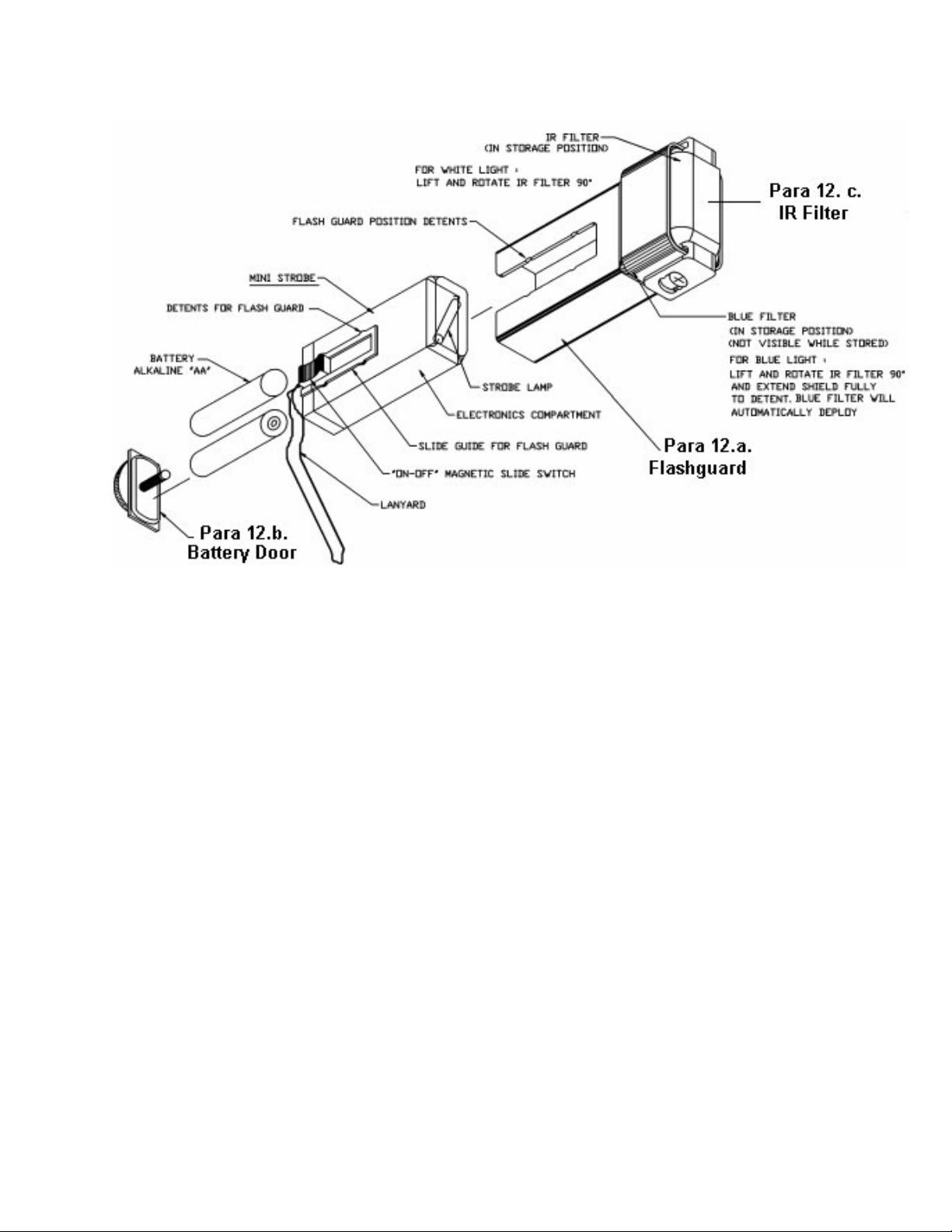
FIGURE 1
8
Y1-03-0146 Rev. D
Page 9

FIGURE 2
9
Y1-03-0146 Rev. D
Page 10

FIGURE 3
10
Y1-03-0146 Rev. D
Page 11

FIGURE 4
11
Y1-03-0146 Rev. D
 Loading...