

Page 1

Installation Manual
Version 1.0
GlobalWatch
™
AIS
Y1-03-0183-1 Rev. A
2
Y1-03-0183-1 Rev. A
Page 2

Y1-03-0183-1 Rev. A
Please read this first!
Warning:
Although ACR strives for accuracy in all its publications; this material may contain errors or
omissions, and is subject to change without prior notice. ACR shall not be made liable for any
specific, indirect, incidental or consequential damages as a result of its use. ACR
components may only be used in safety of life devices or systems, with the express written
approval of ACR, as the failure of such components could cause the failure of the ACR
device or system. If these fail, it is reasonable to assume that the safety of the user or other
persons may be endangered.
Copying of this document, and giving it to others and the use or communication of the contents
thereof, are forbidden without express authority. Offenders are liable to the payment of damages.
Weitergabe sowie Vervielfältigung dieser Unterlage, Verwertung und Mitteilung ihres Inhaltes
nicht gestattet, soweit nicht ausdrücklich zugestanden. Zuwiderhandlungen verpflichten zu
Schadenersatz.
Toute communication ou reproduction de ce document, toute exploitation ou communication
de son contenu sont interdites, sauf autorisation expresse. Tout manquement à cette règle
est illicite et expose son auteur au versement de dommages et intérêts.
Sin nuestra expresa autorización, queda terminantemente prohibida la reproducción total o
parcial de este documento, así como su uso indebido y/o su exhibición o comunicación a
terceros. De los infractores se exigirá el correspondiente resarcimiento de daños y perjuicios.
GlobalWatch
TM
AIS Installation Manual I Version 1.0
2
Page 3

GlobalWatch
Y1-03-0183-1 Rev. A
TM
AIS Installation Manual
2
Index Page Number
1 GENERAL INTRODUCTION ................................................................................ 1
1.1 Description of AIS........................................................................................... 1
2 GLOBALWATCH
TM
AIS....................................................................................... 2
2
2.1 System Overview ........................................................................................... 2
3 INSTALLATION .................................................................................................... 3
3.1 Installation Requirements............................................................................... 3
3.2 Installation Overview ...................................................................................... 3
3.3 Installation of VHF / GPS Antennas ............................................................... 6
4 STARTING THE GLOBALWATCH
TM
AIS............................................................ 8
2
4.1 MMSI Number: ............................................................................................... 8
4.2 Service and User Passwords: ........................................................................ 9
4.3 Changing the MMSI / IMO Numbers ............................................................ 13
4.4 Inputing Voyage Related Data – (User Password Protected)....................... 15
4.5 Setting Ship Related Data – (User Password Protected) ............................. 16
5 TROUBLESHOOTING........................................................................................ 18
5.1 Reading and understanding Alarms: ............................................................ 18
5.2 Alarm Codes ................................................................................................ 19
5.3 Text Messages............................................................................................ 20
6 ACCESSORIES.................................................................................................. 21
7 CONTACT AND SUPPORT INFORMATION...................................................... 21
8 TECHNICAL INFORMATION ............................................................................. 22
8.1 ANNEX......................................................................................................... 23
(1) MMSI Form
(2) Dimensional Drawings
(3) Connection Drawings
(4) Quick Replacement Guide
(5) Transponder Installation checklist
GlobalWatch
TM
AIS Installation Manual II Version 1.0
2
Page 4

History of Changes
Y1-03-0183-1 Rev. A
Date
2004-09-01 1.0.0 Released Team
Version Status
Comments
Responsible
GlobalWatch
TM
AIS Installation Manual III Version 1.0
2
Page 5

1 General Introduction
Y1-03-0183-1 Rev. A
1.1 Description of AIS
What does the abbreviation AIS stand for?
AIS stands for: “Automatic Identification System”
What is AIS?
According to IALA regulations, AIS is defined as follows:
Very simply, the AIS is a broadcast Transponder system, operating in the VHF maritime
mobile Band. It is capable of sending ship information such as identification, position
course, speed and more, to other ships and to shore. It can handle multiple reports at
rapid update rates and uses Self-Organizing Time Division Multiple Access (SOTDMA)
technology to meet these high broadcast rates and ensure reliable and robust ship to ship
operation.
What are the performance standards of AIS?
The IMO defines the performance standards as follows:
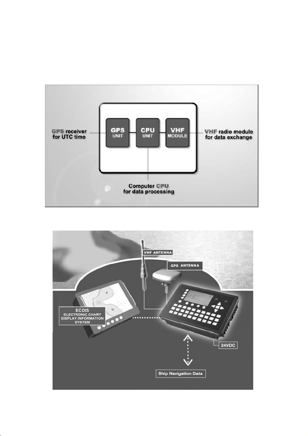
Which modules make up an AIS-Transponder?
The Modules:
Appropriate application software connects the individual modules.
In which modes does AIS function?
AIS is required to function flawlessly in a variety of modes. The relevant regulations require:
The system shall be capable of
- Ship to Ship working
- Ship to Shore working, including Long Range Application
- Automatic and continuous operation
- Provision of information messaging
- Utilization of maritime VHF channels
- GPS receiver
- VHF Radio
- Antenna
- Computer (CPU)
- Power Supply
- An "autonomous and continuous" mode for operation in all areas. This mode
shall be capable of being switched to/from one of the following alternate modes by
a competent authority;
- An "assigned" mode for operation in an area subject to a competent authority
responsible for traffic monitoring such that the data transmission interval and/or
time slots may be set remotely by that authority;
- A "polling or controlled" mode, where the data transfer occurs in response to
interrogation from a ship or competent authority.
GlobalWatch
TM
AIS Installation Manual 1 Version 1.0
2
Page 6
2 GlobalWatch
Y1-03-0183-1 Rev. A
TM
2
AIS
2.1 System Overview
Unlike other AIS devices, the
cabinet. Additionally, the
GlobalWatch
GlobalWatch
features (easy mounting & installation, environmental protection, smallest dimensions).
TM
AIS combines all required functions into one
2
TM
AIS gives the operator a number of additional
2
GlobalWatch
TM
AIS Installation Manual 2 Version 1.0
2
Page 7

3 Installation
Y1-03-0183-1 Rev. A
3.1 Installation Requirements
General Requirements
Please note that international conventions, regulations, instructions and guidelines have to be
adhered to when installing the
GlobalWatch
TM
2
AIS.
The following points must be observed before installation can commence:
- Permission by the local authority to install such a device must be granted.
- Trained service personnel must undertake the installation.
- The
GlobalWatch
TM
AIS must be fitted in a suitable place on the bridge.
2
- The VHF and GPS Antennas must be installed in a suitable position, where excellent
reception conditions apply
(refer to Chapter 3.4 Installation of VHF antenna – page 6)
- All available interfaces must be installed.
- The vessels power supply must suffice, and the GMDSS power supply has to be
used.
3.2 Installation Overview
Survey
AIS is considered part of the ship’s radio station and is surveyed together with radio
installation. Surveys on SOLAS Convention ships should be carried out in accordance with
the rules laid down in IMO Res. A 746(18) "Survey Guidelines under the harmonised system
of survey and certification" (R) 8, and "Protocol of 1988 relating to the International
Convention for the Safety of Life at Sea, 1974."
The
GlobalWatch
Step-by-Step Installation Procedure:
TM
AIS consists of one unit, which integrates all necessary modules.
2
• Mount the
GlobalWatch
TM
AIS close to ships operator workstation for traffic
2
surveillance and maneuvering.
• Use the VHF adapter cable to connect the VHF and GPS antenna cables as well as
the antennas.
• The sensor ECDIS can be connected to the
GlobalWatch
TM
AIS cabinet by the AIS
2
cable.
The device is driven by a 24V DC 7A supply, which is connected to the power terminal
at the connection box. The AIS should be connected to an emergency power source.
A battery capacity calculation together with GMDSS-equipment is needed!
• After performing these steps, the
• The
GlobalWatch
TM
AIS has a ground terminal which has to be connected to ship
2
GlobalWatch
TM
AIS automatically starts operation.
2
ground.
• Now configure the required initial system parameters according to Chapter 4 “Starting
the
GlobalWatch
TM
AIS” on page 8.
2
GlobalWatch
TM
AIS Installation Manual 3 Version 1.0
2
Page 8

Y1-03-0183-1 Rev. A
GlobalWatch
TM
AIS Connection Diagram
2
Note: The ACR connection box includes a fuse of 6,3A. If it is not used, then the unit has to
be protected against high current by an external slow blow fuse of 6,3A.
GlobalWatch
TM
AIS Installation Manual 4 Version 1.0
2
Page 9

Components and Interfaces
Y1-03-0183-1 Rev. A
The diagram below illustrates which devices can be connected to the
GlobalWatch
TM
2
AIS.
Interface Designation Speed Direction
ECDIS CH 4 38400bps Input/Output
GlobalWatch
TM
AIS Installation Manual 5 Version 1.0
2
Page 10

Y1-03-0183-1 Rev. A
3.3 Installation of VHF / GPS Antennas
Interference to the Ship’s VHF Radiotelephone
The AIS ship borne equipment, like any other ship borne transceiver operating in the VHF
maritime band, may cause interference to a ship’s VHF radiotelephone. Because AIS is a
digital system, this interference may occur as a periodic (e.g. every 20 seconds) soft clicking
sound on the ship’s radiotelephone. This affect may become more noticeable if the VHF
radiotelephone antenna is located close to the AIS VHF antenna, and when the
radiotelephone is operating on channels near the AIS operating channels (e.g. channels 27,
28 and 86).
Attention should be paid to the location and installation of the various antennas, in order to
support the antenna characteristics in the best possible way.
VHF Antenna Installation
Antenna Location
Location of the mandatory AIS VHF-antenna should be carefully considered. Digital
communication is more sensitive than analogue/voice communication to interference created
by reflections caused by obstructions such as masts and booms. It may be necessary to
relocate the VHF radiotelephone antenna to minimize interference effects.
To minimise interference effects, the following guidelines apply:
• The AIS VHF antenna should have omni directional vertical polarisation providing 3 to 5
dB gain.
• The AIS VHF antenna should be placed in an elevated position, as free standing as
possible, with a minimum of 2 metres in horizontal direction from constructions made of
conductive materials. The antenna should not be installed close to any large vertical
obstruction. The AIS VHF antenna should have a visible sky of 360°.
• The AIS VHF antenna should be installed at least 3 meters away from interfering highpower energy sources such as radar and other transmitting radio antennas, and out of the
way of the transmitting beam.
• There should not be more than one antenna on each level. The AIS VHF antenna should
be mounted directly above or below the ship’s primary VHF radiotelephone antenna, with
no horizontal separation and a minimum of 2 metres vertical separation. If it is located on
the same level as other antennas, the distance apart should measure at least 10 metres.
See also sample for antenna layout in the Appendix.
Cabling
The cable should be kept as short as possible to minimise attenuation of the signal. Double
shielded coaxial cables equal to or better than RG214 are recommended.
RG214 at VHF attenuation per meter of app. 0,07 dB/m (45m = 3,15db)
VHF AIS frequency app. 162MHz
All outdoor connectors on the coaxial cables should be fitted with preventive isolation, such
as shrink-stocking with silicone to protect the antenna cable against water penetration.
GlobalWatch
TM
AIS Installation Manual 6 Version 1.0
2
Page 11

Coaxial cables should be installed in separate signal cable channels/tubes, and at least 10
Y1-03-0183-1 Rev. A
cm away from any power supply cables. Crossing of cables should take place at right angles
(90°). Coaxial cables should not be exposed to sharp bends, which may lead to changes to
the characteristic impedance of the cable. The minimum bend radius should be 5 times the
cables outside diameter.
Grounding
Coaxial down-leads must be used for all receiving antennas, and the coaxial screen should
be connected to the ground at one end.
GNSS Antenna installation
A Class A AIS must be connected to a GNSS antenna.
Location
The GNSS antenna must be installed where it has a clear view of the sky, so that it accesses
the horizon freely through 360°, with a vertical observation of 5 to 90 degrees above the
horizon. Small diameter obstructions, such as masts and booms, do not seriously impair
signal reception, but such objects must not eclipse more than a few degrees of any given
bearing.
The antenna must be located at least three meters away from, and out of the transmitting
beam of high-power transmitters (S-Band Radar and/or Inmarsat systems). This includes the
ship’s own AIS VHF antenna, if it is designed and installed separately.
Cabling
To achieve optimum performance, the gain of the antenna pre-amplifier should match the
cable attenuation. The resulting installation gain (pre-amplifier gain - cable attenuation)
should be within 0 to 10 dB.
RG214 at GPS attenuation per meter of app. 0,35 dB/m (45m = 15,75dB)
GPS frequency app. 1,2GHz
The coaxial cable between the antenna and the AIS ship borne station connector should be
routed directly, in order to reduce electromagnetic interference. The cable should not be
installed close to high-power lines, such as radar or radio-transmitter lines, or near the AIS
VHF antenna cable. A space of one meter or more is recommended in order to avoid
degradation due to RF-coupling. Crossing of antenna cables should take place at 90 degrees,
to minimise magnetic field coupling.
Antenna Layout
The position of the VHF und GNSS – antennas must be added to the existing antenna layout
of the vessel.
GlobalWatch
TM
AIS Installation Manual 7 Version 1.0
2
Page 12

4 Starting the GlobalWatch
Y1-03-0183-1 Rev. A
After completing the hardware, antennas and external equipment installation, the initial
system start-up can commence. To start the system, connect the
power supply.
The next step is to enter the configuration like password and the MMSI number
L
BoatU.S is an organization for advancing the interests of boaters. The “BoatU.S. MMSI
Program” has been certified by both the Federal Communications Commission and the U.S.
Coast Guard to assign MMSI numbers to vessels with DSC capable radios that are not
required by law to carry a radio, and do not make international voyages or communications.
Please use the printer friendly MMSI# Assignment Form from Annex 1. You may printout this
form, fulfil it and return it to BoatU.S. via fax (number mentioned below). Please proceed in
the following steps:
1. Complete the MMSI Assignment Form from Annex 1.
2. The fields marked with an asterisk (*) should be completed in order to receive an MMSI
number.
3. Refer to the Ship Classification table when completing the Ship Classification question.
4. Return the Assignment Form (see Annex 1) to:
BoatU.S. MMSI Program
880 S. Pickett St.
Alexandria, VA 22304.
Fax to: 703-461-2840
MMSI Info Line: 800-563-1536
You can also fulfil the form directly on the website: www.boatus.com/mmsi.
4.1 MMSI Number:
TM
2
AIS
GlobalWatch
TM
AIS with the
2
.
GlobalWatch
TM
AIS Installation Manual 8 Version 1.0
2
Page 13

4.2 Service and User Passwords:
Y1-03-0183-1 Rev. A
The Transponder system is equipped with two separate Passwords.
1) The User Password, which is the lower security level allows access to all menus except
Menu 6: Service Configuration - please refer to the User Manual for further details on
password protection.
2) The Service Password is required in order to enter the Service Configuration Menu. This is
a higher security level than can be accessed with the User Password and therefore ensures
that the Service Configuration is protected, and limited to authorized service personnel.
The master of the vessel has to ensure that only authorised persons are allowed to make
changes to the Service Configuration and ensures that the newly reset password is stored
very carefully, as it can not be reset from the default “NAUT” a second time.
A master key is not available.
Changing the Service Password
Select “Service Configuration” from the Main Menu with the cursor button [Up] & [Down] or
press Nr. 6 on the keyboard.
N 1^19' E 0^13' |1>0.01|2>1.30|3>1.80nm
|--------------------------------- | Menu
-----| |
| +- 1. Messages
View | +- 2. AIS Status
| +- 3. Voyage Settings
-----| +- 4. Ship Settings
| +- 5. Transponder Configuration
Msg. | +- 6. Service Configuration
| +- 7. Display Settings
-----|
|
Displ|
---------------------------------------NUM| Select->| | |<-Back
Note:
The User and Service Passwords are set to “NAUT” – please reconfigure them immediately
after Transponder initial operation. Store the new passwords very carefully.
The password query field appears. Input new Service Password and press [Enter].
GlobalWatch
TM
AIS Installation Manual 9 Version 1.0
2
Page 14

N 1^24' E 0^17' |1>0.10|2>1.30|3>1.80nm
Y1-03-0183-1 Rev. A
----------------------------------------
++++++++++++++++++++++++++++++++++++++++
Service password protected!
Please enter service password:
++++++++++++++++++++++++++++++++++++++++
--------------------------------------- | Enter | | | Exit
Select Submenu 1 “Change Service Password” with cursor button [Up] & [Down] by pressing
Nr. 1 on the keyboard.
N 1^21' E 0^14' |1>0.01|2>1.30|3>1.80nm
|--------------------------------- | 6. Service Configuration
-----| |
| +- 1. Change Service Password
View | +- 2. User Password Settings
| +- 3. Change MMSI / IMO
-----| +- 4. Restore Factory Settings
|
Msg. |
|
-----|
|
Displ|
---------------------------------------NUM| Select->| | |<-Back
GlobalWatch
TM
AIS Installation Manual 10 Version 1.0
2
Page 15

Y1-03-0183-1 Rev. A
Enter the new Password:
Repeat the new Password:
A minimum of 4, a maximum of 8 characters are allowed. Should the new password include
numbers, use the shift key to generate them.
N 1^25' E 0^18' |1>0.10|2>1.30|3>1.80nm
******* Change Service Password ********
Enter new password :
Repeat new password:
{Length: 4..8 characters}
--------------------------------------- | Save | | | Back
Press Save to store the change.
Changing the User Password
Select Submenu 2 “User Password Settings” with cursor button [Up] & [Down] by pressing Nr.
2 on the keyboard.
N 1^21' E 0^14' |1>0.01|2>1.30|3>1.80nm
|--------------------------------- | 6. Service Configuration
-----| |
| +- 1. Change Service Password
View | +- 2. User Password Settings
| +- 3. Change MMSI / IMO
-----| +- 4. Restore Factory Settings
|
Msg. |
|
-----|
|
Displ|
---------------------------------------NUM| Select->| | |<-Back
GlobalWatch
TM
AIS Installation Manual 11 Version 1.0
2
Page 16

Select Submenu 1 “Change User Password” with cursor button [Up] & [Down] by pressing Nr.
Y1-03-0183-1 Rev. A
1 on the keyboard.
N 1^21' E 0^14' |1>0.01|2>1.30|3>1.80nm
|--------------------------------- | 6-2. User Password Settings
-----| |
| +- 1. Change User Password
View | +- 2. Change Password Protection
|
-----|
|
Msg. |
|
-----|
|
Displ|
---------------------------------------NUM| Select->| | |<-Back
Enter the new Password:
Repeat the new Password:
A minimum of 4, a maximum of 8 characters are allowed. Should the new password include
numbers, use the shift key to generate them.
N 1^25' E 0^18' |1>0.10|2>1.30|3>1.80nm
******* Change User Password ***********
Enter new password :
Repeat new password:
{Length: 4..8 characters}
--------------------------------------- | Save | | | Back
Press Save to store the changes.
GlobalWatch
TM
AIS Installation Manual 12 Version 1.0
2
Page 17

Y1-03-0183-1 Rev. A
4.3 Changing the MMSI / IMO Numbers
Select “Service Configuration” from the Main Menu with the cursor button [Up] & [Down] or
press Nr. 6 on the keyboard.
N 1^19' E 0^13' |1>0.01|2>1.30|3>1.80nm
|--------------------------------- | Menu
-----| |
| +- 1. Messages
View | +- 2. AIS Status
| +- 3. Voyage Settings
-----| +- 4. Ship Settings
| +- 5. Transponder Configuration
Msg. | +- 6. Service Configuration
| +- 7. Display Settings
-----|
|
Displ|
---------------------------------------NUM| Select->| | |<-Back
Input Service Password and press [Enter].
N 1^23' E 0^16' |1>0.01|2>1.30|3>1.80nm
----------------------------------------
++++++++++++++++++++++++++++++++++++++++
Service password protected!
Please enter service password:
++++++++++++++++++++++++++++++++++++++++
--------------------------------------- | Enter | | | Exit
GlobalWatch
TM
AIS Installation Manual 13 Version 1.0
2
Page 18

Y1-03-0183-1 Rev. A
Select Submenu 3 “Change MMSI/IMO” with cursor button [Up] & [Down] by pressing Nr. 3
on the keyboard.
N 1^21' E 0^14' |1>0.01|2>1.30|3>1.80nm
|--------------------------------- | 6. Service Configuration
-----| |
| +- 1. Change Service Password
View | +- 2. User Password Settings
| +- 3. Change MMSI / IMO
-----| +- 4. Restore Factory Settings
|
Msg. |
|
-----|
|
Displ|
---------------------------------------NUM| Select->| | |<-Back
Input new MMSI / IMO Numbers and press [Save] to store input data. Press [Back] to return
to the Submenu without saving.
Note:
The IMO number 303174162 has to be deleted. If the ship has no IMO registration, then use
number 0 or number 1. It is very important that a number with one digit has to be used!
N 1^21' E 0^14' |1> N/A|2>0.00|3>0.10nm
********** Change MMSI / IMO ***********
MMSI :1193046
IMO No.:303174162
---------------------------------------NUM| Save | | | Back
GlobalWatch
TM
AIS Installation Manual 14 Version 1.0
2
Page 19

Y1-03-0183-1 Rev. A
4.4 Inputing Voyage Related Data – (User Password Protected)
Select “Voyage Settings” from the Main Menu with the cursor button [Up] & [Down]
or press Nr. 3 on the keyboard
Note:
The default User Password is set to “NAUT” – please reconfigure it immediately after
Transponder initial operation
N 1^20' E 0^13' |1> N/A|2>0.00|3>0.10nm
|--------------------------------- | Menu
-----| |
| +- 1. Messages
View | +- 2. AIS Status
| +- 3. Voyage Settings
-----| +- 4. Ship Settings
| +- 5. Transponder Configuration
Msg. | +- 6. Service Configuration
| +- 7. Display Settings
-----|
|
Displ|
---------------------------------------NUM|Select->| | |<-Back
The password query field appears. Input new User Password and press [Enter].
N 1^31' E 0^24' |1>0.01|2>1.30|3>1.80nm
----------------------------------------
++++++++++++++++++++++++++++++++++++++++
User password protected!
Please enter user password:
++++++++++++++++++++++++++++++++++++++++
--------------------------------------- | Enter | | | Exit
GlobalWatch
TM
AIS Installation Manual 15 Version 1.0
2
Page 20

Y1-03-0183-1 Rev. A
Scroll the Voyage Data Fields with [Enter] and input own vessel data. Select a default Cargo
Type and NavStat Setting with the cursor buttons [Left] & [Right].
Save the new settings by pressing [Save], and return to the Main Menu Screen by pressing
[Exit]. Press [Back] to return to the Main Menu without saving any changes.
N 1^18' E 0^12' |1>0.01|2>1.30|3>1.80nm
*********** Voyage Settings ************
Cargo :<N/A or harmless>
Draught :24.8m
PoB :1
Dest. :CASABLANCA
ETA :10/13 12:31
NavStat.:Engaged in fishing
--------------------------------------- | Save | | | Back
4.5 Setting Ship Related Data – (User Password Protected)
Select “Ship Settings” with cursor button [Up] & [Down]
or press Nr. 4 on the keyboard.
Note:
The default User Password is set to “NAUT” – please reconfigure it immediately after
Transponder initial operation
N 1^23' E 0^16' |1>0.01|2>1.30|3>1.80nm
|--------------------------------- | Menu
-----| |
| +- 1. Messages
View | +- 2. AIS Status
| +- 3. Voyage Settings
-----| +- 4. Ship Settings
| +- 5. Transponder Configuration
Msg. | +- 6. Service Configuration
| +- 7. Display Settings
-----|
|
Displ|
---------------------------------------NUM| Select->| | |<-Back
Input new User Password and press [Enter].
GlobalWatch
TM
AIS Installation Manual 16 Version 1.0
2
Page 21

N 1^23' E 0^16' |1>0.01|2>1.30|3>1.80nm
Y1-03-0183-1 Rev. A
----------------------------------------
++++++++++++++++++++++++++++++++++++++++
User password protected!
Please enter user password:
++++++++++++++++++++++++++++++++++++++++
--------------------------------------- | Enter | | | Exit
Scroll the Ship Settings Fields with [Enter] and input own vessel data.
Example: Length = 220m, A = 200m, Beam = 43m, D = 33m
RefPointExt = A200 B20 C10 D33m (location of the external GPS antenna)
A = the distance from bow to the antenna
B= the distance from the antenna to the stern
C = the distance from the port side to the antenna
D = the distance from the antenna to the starboard side
Enter A200D33 (without spaces, no decimals, no commas)
The full line as shown will be displayed: RefPtExt: A200 B20 C10 D33m
B and C are calculated by the AIS.
Enter RetPtInt (location of the internal GPS antenna) in the same way.
Select a default ShipType with the cursor button [Left] & [Right].
Save the new settings by pressing [Save]. Press [Back] return to the Main Menu Screen
without saving any changes.
GlobalWatch
N 1^19' E 0^12' |1>0.01|2>1.30|3>1.80nm
************ Ship Settings *************
/\ +
CallSign:D11233 / \|
ShipName:ANDREA DORIA | |
Length :220m | A
Beam :43m | x--+
RefPtExt:A200 B20 C10 D33m | | B
RefPtInt:A190 B30 C20 D23m +-C-+D-+
ShipType: Pilot vessel
--------------------------------------- | Save | | | Back
TM
AIS Installation Manual 17 Version 1.0
2
Page 22

5 Troubleshooting
Y1-03-0183-1 Rev. A
5.1 Reading and understanding Alarms:
The
GlobalWatch
the user about major system malfunctions and failings in the connected sensors.
The Alarm Status informs the user about all active Alarms. The Alarm will be disabled and
deleted from the Alarm Status, as soon as the displayed problem has been rectified.
The TXT status displays additional sensor information and the UTC clock status.
See tables (page 19) for Alarm and TXT Messages.
Select “AIS Status” with cursor button [Up] & [Down]
or press Nr. 2 on the keyboard.
TM
AIS differentiates between Alarm and TXT messages. An Alarm informs
2
N 1^19' E 0^12' |1> N/A|2>0.00|3>0.10nm
|--------------------------------- | Menu
-----| |
| +- 1. Messages
View | +- 2. AIS Status
| +- 3. Voyage Settings
-----| +- 4. Ship Settings
| +- 5. Transponder Configuration
Msg. | +- 6. Service Configuration
| +- 7. Display Settings
-----|
|
Displ|
---------------------------------------NUM|Select->| | |<-Back
Select “Alarm Status” or “TXT Status” with cursor button [Up] & [Down]
or press Nr. 4 or 5 on the keyboard.
N 1^21' E 0^14' |1> N/A|2>0.00|3>0.10nm
|--------------------------------- | 2. AIS Status
-----| |
| +- 1. State / Conditions
View | +- 2. Own Ship Data
| +- 3. Own VHF Status
-----| +- 4. Alarm Status
| +- 5. TXT Status
Msg. | +- 6. Version Info
| +- 7. Security Log
-----|
|
Displ|
---------------------------------------NUM|Select->| | |<-Back
GlobalWatch
TM
AIS Installation Manual 18 Version 1.0
2
Page 23

Y1-03-0183-1 Rev. A
5.2 Alarm Codes
ID
Description Text
Cause/Source
System Reaction / Remedy
01
AIS: Tx malfunction
AIS: Antenna VSWR
02
exceeds limit
(VSWR - Voltage
Standing Wave Ratio)
AIS: Rx channel 1
03
malfunction
AIS; Rx channel 2
04
malfunction
AIS: Rx channel 70
05
malfunction
06
AIS: General failure
AIS; External EPFS lost
25 (*)
(EPFS = electronic
Position Fixing System
such as GPS)
AIS: No sensor position in
26
use
29
AIS: No valid SOG
information
30
AIS: No valid COG
Information
AIS: Heading lost/invalid
32 (*)
AIS: No valid ROT
35 (*)
Information
VHF Antenna,
cabling
VHF antenna,
installation
Internal error
Internal error
No valid data on
Ch1, Ch2 or Ch3 is
available
No valid position
from internal GPS
or external
position sensor
No valid data from
external speed
sensor or internal
GPS
No valid data from
external sensor or
internal GPS
No valid data from
external sensor
(Gyrocompass)
No ROT indicator is
used.
No valid data from
external sensor
Reaction: The transponder unit stops transmission. If Alarm ID 01
and ID 02 are simultaneously displayed, then a major antenna
problem has arisen.
Remedy:
Check if the antenna is AIS compatible (156-162 MHz) and if the
antenna cabling has a short circuit or is missing any contacts at the
connectors.
If the ID 01 is displayed as a stand alone message, then the unit
requires replacing.
Reaction: The transponder unit continues transmission.
Remedy:
Check the antenna and the antenna cabling (RG214 / 50 Ohm cable
required).
Reaction: The transponder unit stops transmission on the affected
channel,
Remedy;
If this alarm reoccurs regularly, then the transponder unit requires
replacing.
Reaction: The transponder unit stops transmission.
Remedy;
The transponder unit requires replacing.
Reaction: The transponder unit continues operation using the
position data of the internal GPS. If there is no valid position data
available from the internal GPS, error 026 is additionally displayed.
Remedy:
Id 25 indicates that the sentences GLL, GNS, GGA, RMC cannot be
received. Check the sensor and the cabling; check if the system
that delivers the data is working. Check the baud rate settings of the
sensor inputs. AIS requires the protocol NMEA 0183 V3.0!
Reaction: The transponder unit continues operation.
Remedy:
Check the sensor cabling and the antenna of the internal GPS
sensor.
Reaction: The transponder unit continues operation and displays
SOG: N/A
Remedy;
The sentences VBW, VTG, RMC cannot be received. Check the
sensor and the cabling; check if the system that delivers the data is
working. Check the baud rate settings of the sensor inputs. AIS
requires the protocol NMEA 0183 V3.0!
Reaction: The transponder unit continues operation and displays
COG: N/A
Remedy:
The sentences VBW, VTG, RMC cannot be received. Check the
sensor and the cabling, check if the system that delivers the data is
working. Check the baud rate settings of the sensor inputs. AIS
requires the protocol NMEA 0183 V3.0!
Reaction: The transponder unit continues operation
Remedy:
The sentence for HDT cannot be received. Check the sensor and
the cabling, check if the system that delivers the data is working.
Check the baud rate settings of the sensor inputs. Mention AIS
accepts true heading only (no magnetic).
Reaction: The transponder unit continues operation
Remedy:
The sentence for ROT cannot be received. If a Rate Of Turn
indicator is not in use, then it suffices to just acknowledge the
alarm. The Alarm Status will store the information that no ROT
sensor is available. Otherwise, check the sensor and the cabling.
Check if the system that delivers the data is working. Check the
baud rate settings of the sensor inputs. AIS requires the protocol
NMEA 0183 V3.0!
NOTE: Alarm – Messages marked with asterisk (*) will appear on standard workboat
installations due to missing sensor input devices
GlobalWatch
TM
AIS Installation Manual 19 Version 1.0
2
Page 24

Y1-03-0183-1 Rev. A
5.3 Text Messages
ID
Description Text
Cause/Source
Reaction of the System / Remedy
07
AIS: UTC clock lost
AIS: external DGNSS in
21
use
AIS: external GNSS in
22
use
AIS: internal DGNSS in
23
use (beacon) 023
AIS: internal DGNSS in
24
use (message 17)
25
AIS: internal GNSS in
use
27
AIS: external SOG/COG
in use
AIS: internal SOG/COG
28
in use
AIS: Heading valid
31
Internal GPS
Information
Information
Information
Information
additional to Alarm
ID 25
Information
Information
additional to Alarm
ID 29 or ID 30
Information
Reaction: the transponder unit continues operation using indirect or
semaphore synchronisation
Remedy:
Check GPS Antenna for AIS.
Reaction: Positioning is fully operational
Remedy: no action required
Reaction: The transponder unit continues operation using the position
data from a GNSS receiver
Remedy: no action required
Reaction: The transponder unit uses position data from the internal
source. The internal GNSS receiver is capable of processing DGNSS
corrections.
Remedy: no action required
Reaction: The transponder unit continues operation using the position
data from the internal GPS.
Remedy
Check the sensor and the cabling; Check if the system that delivers the
data is working; Check the baud rate settings of the sensor input
Reaction: COG/SOG is in full operation
Remedy: no action required
Reaction: The transponder unit continues operation using the data
from the internal GPS.
Remedy
Check the sensor and the cabling; Check if the system that delivers the
data is working; Check the baud rate settings of the sensor inputs
Reaction: Heading is in full operation
Remedy: no action required
AIS: Rate of Turn
33
Indicator in use
AIS: Other ROT source
34
in use
Information
Information
Reaction: A Rate Of Turn indicator is connected and in full operation
Remedy: no action required
Reaction: The transponder unit is operating with ROT data rather than
with TIROT data - therefore the AIS only differs between + 127 (turning
right at 720 degrees per minute or higher) and – 127 ( turning
left at 720 degrees per minute or higher)
GlobalWatch
TM
AIS Installation Manual 20 Version 1.0
2
Page 25

Y1-03-0183-1 Rev. A
6 Accessories
The Standard Set for the
GlobalWatch
TM
AIS consists of the following products:
2
Category
Description
GlobalWatch
2
TM
AIS
Basic Kit
Mounting:
Antennas:
Cables and Interfaces
1 GlobalWatch
Installation and user manual,
3 caps of plug
1 cable clamp (M5 thread)
3 angles + 3 mounting screws (screw bolt + square nut)
Kit bracket-mounting + 2 wing bolts + 4 screws
GPS Antenna GPS4 (Procom) + mounting
Glomex VHF antenna RA 109 sls + mounting kit
GPS / VHF extender
AIS cable with all interface to ECDIS
TM
AIS Transponder
2
7 Contact and Support Information
ACR Electronics
Customer Service
5757 Ravenswood Road
Drawing
Number
NAU-A271
NAU-D503
NAU-B602+NAU-X6022
NAU-B610
NAU-B550/NAU-B555
NAU-B508
Fort Lauderdale, FL 33312
U.S.A.
Tel.: +1 (954) 981-3333
Fax: +1 (954) 983-5087
info@acrelectronics.com
www.acrelectronics.com
GlobalWatch
TM
AIS Installation Manual 21 Version 1.0
2
Page 26

Y1-03-0183-1 Rev. A
8 Technical Information
PHYSICAL
Size in mm / inch (w) 201,26mm / 7,92inch
Size in mm / inch (h) 60mm / 2,36inch
Size in mm / inch (d) 281,26mm / 11,07inch
Weight 2490g / 5,50pound
Operating Temperature -15°C to +55°C / 5°F to 131°F
POWER SUPPLY
Supply Voltage (galvanic isolated) 24 V DC (-10% +30%)
Input Current min.7 A (24V)
INTERFACES
CH4 ECDIS Port (In- / Output)
in/ out 38400 bps
AIS targets, AIS messages
BUILT IN GPS
Receiver Architecture 12 channel differential
Tracking Capability 12 satellites sim.
Accuracy Horizontal 10m / 2drms *
Accuracy Vertical 15m / 2drms *
GPS Antenna Connector TNC
DGPS Accuracy < 5m / 2drms
*) depends on SA
BIIT – Alarm System
Relay breaking capacity
30V DC 8A
250V AC 8A
KEYBOARD
Integrated alphanumerical
SPECIFIED STANDARDS
IMO MSC.74(69) Annex 3
ITU-R M.1371 (Class A)
IALA Techn.Clar. of ITU-R M.1371-1
(Ed.1.3)
IEC 61993-2 (2002)
IEC 61162-1 (2000) NMEA 0183-3
IEC 61162-2 (1998) NMEA 0183-3
IEC 61162-3 NMEA 2000
ITU-R M.823-2
IEC 61108-1 (1996)
IEC 60 945 (1996)
ITU-R M.825-3
ITU-R M.1084-3
VHF
Frequency Range 156 MHz - 162MHz
Channel Spacing 12.5 or 25kHz
Number of RF Channels 3 Receiv. / 1 Transm.
Number of AIS Receivers 2
Number of DSC Receivers 1
Frequency Error
VHF TRANSMITTER
Output Power
Receive to Transmit Switching Time < 1ms
Transmit release time < 1ms
Automatic shutdown 1 sec.
Channel switching time < 25ms
Attack Time < 1ms
VHF RECEIVER
Max. Useable Sensitivity < -110dBm
Co-channel Rejection > -8dB (25kHz);
> -12dBm (12.5kHz)
Adjacent Channel Selectivity > 70dB (25kHz);
> 60dB (12.5kHz)
Inter-modulation Rejection > 65dB
Spurious Response Rejection > 70dB
Blocking > 84dB
VHF MODEM
Bitrate GMSK 9600 bps
RF Baud Rate (DSC) 1200bps
Modulation GMSK / FSK
SOFTWARE
GlobalWatch
- installed and ready for use
- implemented configuration Software
- User friendly Interface
to System and AIS Information
- additional Interface to System
Configuration
(Windows 2000
HARDWARE
GlobalWatch
DISPLAY
Integrated graphical 240 x 128
2 Watt to 12.5 Watt
TM
AIS Version 2.0.x
2
®
)
TM
AIS Version 1.0.x
2
adjustable brightness
+/- 2.5ppm
(adjustable)
and contrast
GlobalWatch
TM
AIS Installation Manual 22 Version 1.0
2
Page 27

Y1-03-0183-1 Rev. A
8.1 ANNEX
These documents are included on the following pages:
(1) MMSI Form
(2) Dimensional Drawings
(3) Connection Drawings
(4) Quick Replacement Guide
(5) Transponder Installation Checklist
GlobalWatch
TM
AIS Installation Manual 23 Version 1.0
2
Page 28

The BoatU.S. MMSI Program has been certified by both the Federal Communications Commission and the
U.S. Coast Guard to assign MMSI numbers to vessels with DSC capable radios that are not required
by law to carry a radio, and do not make international voyages or communications.
Following is a printer friendly MMSI# Assignment Form.
You may download this form and return it to BoatU.S. via mail or fax.
IMPORTANT NOTE
Depending on the manufacturer of your DSC radio, your MMSI# may only be able to be entered twice during
the initial set up process. If you try to program your radio more than twice with the assigned MMSI#, the radio
may have to be sent back to the manufacturer. Please be careful when initially entering your newly assigned
MMSI number.
INSTRUCTIONS
1. Complete the MMSI Assignment Form on the next page.
2. Note the required fields as indicated by an(*).
These fields must be completed in order to receive an MMSI number.
3. Refer to the Ship Classification table when completing the Ship Classification question.
4. Return the Assignment Form (next page) to:
Fax to:
BoatU.S. MMSI Program BoatU.S. MMSI Program
880 S. Pickett St. OR 703-461-2840
Alexandria, VA 22304. MMSI Info Line: (800) 563-1536
The MMSI ASSIGNMENT FORM may be found on the next page (scroll down to view on the web browser).
Y1-03-0183-1 Rev. A
Page 29

MMSI ASSIGNMENT FORM
* Denotes a required field. These fields must be completed in order to receive an MMSI#.
*OWNER‘S FIRST NAME:
* OWNER‘S LAST NAME:
OR COMPANY NAME:
* STREET ADDRESS:
* CITY: * STATE:
* ZIP CODE: PROVINCE, MAIL CODE, COUNTRY:
*OWNER‘S HOME PHONE:
OWNER‘S WORK PHONE: EMAIL ADDRESS:
*PRIMARY EMERGENCY CONTACT ASHORE:
*PRIMARY CONTACT HOME PHONE:
PRIMARY CONTACT WORK PHONE:
ALTERNATE CONTACT ASHORE:
ALTERNATE CONTACT HOME PHONE:
ALTERNATE CONTACT WORK PHONE:
VESSEL NAME: RADIO CALL SIGN:
VESSEL WIRELESS PHONE 1: WIRELESS 2:
VESSEL WIRELESS PHONE 3: WIRELESS 4:
VESSEL FLAG STATE:
*SHIP CLASSIFICATION (SEE TABLE BELOW):
EX-SHIP NAME (IF KNOWN):
EX-CALL SIGN (IF KNOWN): EPIRB ID CODE:
*VESSEL REGISTRATION/DOCUMENTATION NUMBER:
*VESSEL HOME PORT:
PORT CITY: PORT STATE:
ALTERNATE VESSEL HOME PORT:
*CAPACITY (# OF PERSONS EXPECTED TO BE ON BOARD):
SHIP‘S RADIO INSTALLATION (VHF, DSC, MF/HF WITH DSC, MF/HF W/O DSC,
AIS TRANSPONDER, CELLULAR PHONE #, ETC.):
REMARKS (BOAT LENGTH, COLOR, TYPE, ETC.):
*The SHIP CLASSIFICATION TABLE may be found on the next page (scroll down to view on the web browser).
Y1-03-0183-1 Rev. A
Page 30

SHIP CLASSIFICATION TABLE
RECREATIONAL VESSELS
DUN - KETCH
MTB - MOTOR BOAT
SLO - SLOOP
YAT - YACHT
GOL - SCHOONER
VLR - SAILING SHIP
COMMERCIAL VESSELS & SHIPS OF WAR
ACV - AIR CUSHION VEHICLE
AVI - DISPATCH VESSEL
BAR - LIGHTER
BLN - WHALER
BLS - BUOY SHIP
CA - CARGO SHIP
CAB - COASTER
CGT - COAST GUARD
CHA - BARGE
CIM - CEMENT CARRIER
CIT - TANKER
CON - CONTAINER SHIP
COR - CORVETTE
DES - DESTROYER
DIV - USED BY DIVERS
DOU - CUSTOMS LAUNCH
DRG - DREDGER
ECO - TRAINING SHIP
EXP - RESEARCH SHIP
FPS - FAST PATROL SHIP
INS - INSPECTION SHIP
FRG - REEFER
LAN - LOBSTER SHIP
FRM - WEATHER SHIP
AUX - AUXILIARY SHIP
FRT - FRIGATE
BLK - BULK CARRIER
FRU - FRUIT CARRIER
BTA - FACTORY SHIP
GEN - GENERAL CARGO
CBL - CABLE SHIP
GRC - GRAIN CARRIER
CHR - TRAWLER
GRF - FLOATING CRANE
COA - COLLIER
GS - WARSHIP
CRO - CRUISER
HOP - HOSPITAL SHIP
DMN - MINESWEEPER
HYD - HYDROGRAPHIC
DRY - DRY CARGO
ICE - ICE BREAKER
FBT - FERRY
ICN - WASTE INCINERATOR
LOU - LUGGER
PH - FISHING VESSEL
MOR - BANKER
PHA - LIGHTSHIP
MOU - MINE LAYER
PHR - LIGHTHOUSE TENDER
NET - POLLUTION CLEARANCE
PHS - FISHING GUARD
NVP - NAVIPLANE
PLE - PLATFORM
OBO - ORE,BULK OIL
PLT - PILOT TENDER
OIL - OIL TANKER
PMP - FIREFLOAT
OSC - OCEANOGRAPHIC
PMX - CARGO/PASSENGER
OSV - OCEAN STATION
PON - PONTOON
PA - PASSENGER SHIP
PTA - AIRCRAFT CARRIER
PAQ - LINER
PTH - HELICPOTER CARRIER
PBE - LIVESTOCK SHIP
RAM - SALVAGE SHIP
PCH - BARGE CARRIER
RAV - SUPPLY SHIP
ROU - RORO SHIP
TPT - TRANSPORT
SAE - RESCUE VESSEL
TPW - FOREST PROD. CARRIER
SEC - STANDBY SAFETY VSL
TRA - TRAMP
SMN - SUBMARINE
TUG - PUSHER TUG
SRV - PATROL SHIP
TVH - VEHICLE CARRIER
THO - TUNNY SHIP
VDO - LAUNCH
TPG - LIQUID GAS CARRIER
VDT - HYDROFOIL
TPO - ORE CARRIER
XXX - UNSPECIFIED
TPS - SOLVENT CARRIER
ROC - ROCK BREAKER
PER - DRILLING UNIT
CTR - CUTTER
ESC - ESCORT SHIP
Y1-03-0183-1 Rev. A
Page 31

Y1-03-0183-1 Rev. A
Page 32

Y1-03-0183-1 Rev. A
Page 33

Y1-03-0183-1 Rev. A
Page 34

Y1-03-0183-1 Rev. A
Page 35

Y1-03-0183-1 Rev. A
Page 36

Y1-03-0183-1 Rev. A
Page 37

1,5m ± 10mm
4
5
6,7
1)
3) 5)
50±5
1,2
3
3) 4)
1
16,17,33
48,49,32
21
22
20
18
19
+
-
4
3
5
2
1
1)
2)
Paar verdrillt
1 2 3 4 5 6 7 8
Y1-03-0183-1 Rev. A
A3
A
A
1
B
B
Masse:
6
C
D
Blatt
1
Bl.
1
C
D
sonders fur den Fall der Patenterteilung oder GM-Eintragung.
pflichten zu Schadenersatz. Alle Rechte vorbehalten, insbe-
nicht ausdrucklich zugestanden. Zuwiederhandlungen ver-
wertung und Mitteilung ihres Inhaltes nicht gestattet, soweit
Weitergabe sowie Vervielfaltigung dieser Unterlage, Ver-
E
6)
1) aufgeqetscht
2) Schirm auf Schale Pos 1 gelötet
3) Beschriftung unverwischbar aufgebracht
(Siebdruck oder Klebeschild)
4) Beschriftung: "NAU-B508"
Schiftgröße min. 2mm
5) Beschriftung: "CH4"
"ext. Display"
6) Pos. 4, 5 auf Pos. 1, 6 gelötet
F
1 2 3 4
6)
CH 4
ext. Display
in +
in in gnd
out +
out -
ANLIEFERFORM: Zu Ring gebunden, verpackt in PE-Beutel
NAUTICAST
02
Änderung
01 12.11.2002 W50
PDM-Neuausgabe
51 W50
Mitteilung
14.09.2004
27.05.2002
NAU
DatumZust.
Name
Toleranz
ISO 2768-mK
Datum
27.05.2002
Bearb.
W50 MAT
Gepr.
W50 HL
System AutoCad 2002
Maßstab:
1:1
---
AIS Cable with assembled plugs / Workboat
NAU-B508-*-06
File:
Page 38

10m ±10mm
1,2
3
2) 3)
5
4
7
6
1)
1)
1)
1)
A1
A2
VHF-Stecker
TNC
A3
6
7
1 2 3 4 5 6 7 8
Y1-03-0183-1 Rev. A
A
B
C
1
A
B
C
D
sonders fur den Fall der Patenterteilung oder GM-Eintragung.
pflichten zu Schadenersatz. Alle Rechte vorbehalten, insbe-
nicht ausdrucklich zugestanden. Zuwiederhandlungen ver-
wertung und Mitteilung ihres Inhaltes nicht gestattet, soweit
Weitergabe sowie Vervielfaltigung dieser Unterlage, Ver-
D
A3
1) Pos 4 auf Stecker 1, 6, 7 anschlagen
(gecrimpt bzw. gelötet)
E
F
1 2 3 4
2) Beschriftung unverwischbar aufgebracht
(Siebdruck oder Klebeschild)
3) Beschriftung "NAU-B555"
Schriftgröße min. 2mm
Hinweis:
Pos 1 bis 3 und 5 bis 7 erfüllen nicht die nach EN60945 definierten
Umweltanforderungen wie
-Schutzart IP67
-Salzsprühnebeltest
-Korrosionsbeständigkeit
ANLIEFERFORM: Zu Ring gebunden, verpackt in PE-Beutel, beschriftet
Datum
Bearb.
Gepr.
System AutoCad 2002
NAU
Name
Toleranz
ISO 2768-mK
27.05.2002
W50 MAT
W50 HL
NAUTICAST
02
Änderung
01 29.11.2002 W50
PDM-Neuausgabe
51 W50
Mitteilung
14.09.2004
27.05.2002
DatumZust.
Maßstab:
1:1
Masse:
---
GPS/VHF Workboat cable (TNC plug + PL plug)
NAU-B555-*-06
File:
Blatt
1
Bl.
1
Page 39

Y1-03-0183-1 Rev. A
Source, Draw.-No. 46-EX-D-X00001-C, coyright Raytheon Marine GmbH, Kiel, Germany
Page 40

Quick Replacement Guide
X-Pack DS
1. Prepare the following tools:
Screwdrivers, spanners
User Password: your personal password
(factory default setting is ‘NAUT’)
2. Read out your Transponder conguration
Steps to do this:
Press
Menu
Press
2
2.AIS Status
Press
2
2.Own Ship Data
Write down the current conguration settings here:
IMO No. : Dest :
ShipName : EAT :
ShipType : MMSI :
Length : CS :
Cargo : Beam :
Draught :
Press
Menu
Press
4
4.Ship Settings
Password
[UserPassword] [Enter
]
Write down the current conguration settings here:
RefPtExt: A B C D RefPtInt: A B C D
Press
Menu
Press
5
5.Transponder Conguration
Password
[UserPassword] [Enter
]
Press
5
5.Sensor Settings
Write down the current conguration settings here:
BaudRate Sensor1:
BaudRate Sensor2:
BaudRate Sensor3:
Press
M8
Back
3. Detach the device
3.1. Bracket Mounting
3.2. Frame Mounting
4. Disconnect cables
4.1. AIS-Cable to unscrew
4.2. VHF/GPS Cable to unscrew
5. Unpack the new Transponder
Y1-03-0183-1 Rev. A
Page 41

6. Connect cables
6.1. AIS-Cable to screw on
6.2. VHF/GPS Cable to screw on
7. Mount the replacement unit
7.1. Bracket Mounting
7.2. Frame Mounting
8. Key in the conguration settings from above:
Following steps to key in the Conguration
Press
Menu
Press
6
6.Service Conguration
Password
NAUT [Enter
]
(Default Factory Password)
Press
3
3.Change MMSI / IMO
Key in the conguration data from your list: (see page 1)
MMSI: IMO No:
Press
M5
Save
Press
Menu
Press
4
4.Ship Settings
Password
NAUT [Enter
]
(Default Factory Password)
Key in the conguration data from your list: (see page 1)
CallSign: ShipName: Length: Beam:
RefPtExt:
AxxCxx*
RefPtInt:
AxxCxx*
ShipType:
*(B and D are calculated by the AIS)
Press
Menu
Press
5
5.Transponder Conguration
Password
NAUT [Enter
]
(Default Factory Password)
Press
5
5.Sensor Settings
Key in the conguration data from your list: (see page 1)
BaudRate Sensor1: BaudRate Sensor2: BaudRate Sensor3:
Press
M5
Save
9. Check the functionality
Press
M2
You should see correct values for LAT, LON, SOG, COG, and Time
Press
M2
You should see your Own Ship Data as noted down before.
9.1. Change your User Password
Press
Menu
Press
6
6.Service Conguration
Password
NAUT [Enter
]
(Default Factory Password)
Press
2
2.User Password Settings
Press
1
1.Change User Password
Enter
[new password]
Repeat
[new password]
Press
M5
Save
Y1-03-0183-1 Rev. A
Page 42

Y1-03-0183-1 Rev. A
Page 1 of 2
Transponder Installation Checklist
Please fill out your contact and vessel details below:
Vessel Location
(Port and country)
Ship Name
Company Name Installer
Company Name Reseller
Contact Name
Contact Telephone number
Contact Email
Please fill out the Transponder details below:
You will find the serial Number on the back side under the barcode.
Product
Serial Number
Software Version
Installation Date
Please list which peripheral equipment is connected– state equipment manufacturer and
type specification:
Power Supply
Antenna Type GNSS
Antenna Type VHF
Cable type
Cable length
Antenna Position
GNSS Antenna position
Please describe your antenna position below or add an antenna layout to this
document. If possible, include antenna evaluation.
VHS Antenna position
Connection Box
(optional)
Which sensors have been connected? (Please state manufacturer and type specification).
YES NO
N:\Technik\TechnicalSupport\Prozess_Doku\InstallationChecklist_V02us.doc
Page 43

Y1-03-0183-1 Rev. A
Page 2 of 2
Sensor CH1 (optional)
Sensor CH2 (optional)
Sensor CH3 (optional)
Channel 4
Channel 5 (optional)
Channel 8 (optional)
Channel 9 (optional)
Converter Type
Transponder Configuration:
IMO No (if available)
MMSI
ShipName CS
ShipType Length
Beam Draught
Cargo Destination
RefPtExt: A B C D RefPtInt: A B C D
BaudRate Sensor1:
BaudRate Sensor2:
BaudRate Sensor3:
Functionality Check:
Now check your Transponder functionality - the correct values for LAT, LON, SOG, COG, and
Time should appear.
Reading out the Alarm Status, the Installation Manual includes a Tabel for reaction of system and
remedy.
Please list the invoked Alarms:
Alarm type: Yes No Alarm type Yes No
ID 01 Tx-Malfunction ID 02 VSWR limit
ID 03 Rx ch1 Malfunction ID 04 Rx ch2 Malfunction
ID 05 Rx ch70 Malfunction ID 06 General failure
ID 25 External EPFS lost *) ID 26 No Sensor
ID 29 No valid SOG info ID 30 No valid COG info
ID 32 Heading lost/invalid *) ID 35 No valid ROT info *)
*) will appear at workboat installation
Please return this form by Email after Transponder installation to Nauticast Technical
Support Department to info@ais-shop.com
If Email is not available, please fax this form to: 866-XPACKUS (866-972 2587)
Erstellt: C. Moore
Geprüft: B. Werner
Freigegeben: A. Lesch
Gültig ab: 20.09.2004
N:\Technik\TechnicalSupport\Prozess_Doku\InstallationChecklist_V02us.doc
 Loading...