

Page 1

PRODUCT
SUPPORT
MANUAL
Y1-03-0164
Rev. A
FPR-10™
Product No. 2784
Field Programmer Reader
ACR Electronics, Inc.
5757 Ravenswood Road
Fort Lauderdale, Fl 33312
+1(954) 981-3333 • Fax +1 (954) 983-5087
www.acrelectronics.com
Email: Info@acrelectronics.com
A Chelton Group company
Page 2

1
TABLE OF CONTENTS
1.0 OVERVIEW ........................................................................................................2
2.0 WARNINGS ........................................................................................................ 2
3.0 BEFORE YOU RUN SETUP..............................................................................3
3.1 FPR-10 COMPONENTS.................................................................................3
3.2 CHECK THE HARDWARE AND SYSTEM REQUIREMENTS................................. 3
4.0 INSTALLING THE FPR-100/10 SOFTWARE ................................................. 3
4.1 ADDING A PRINTER.....................................................................................4
5.0 USING THE FPR-10........................................................................................... 4
5.1 PROGRAMMING THE MESSAGE ....................................................................4
5.2 PRINTING HEXADECIMAL LABELS................................................................7
5.3 READING THE MESSAGE..............................................................................8
Figure 1 – Product Selection Menu.................................................................................... 9
Figure 2 – Option Selection Menu...................................................................................10
Figure 3 – Protocol Selection Menu................................................................................. 11
Figure 4 – Memory Read Display....................................................................................11
Figure 5 – PC / FPR-100 Cable Connections .................................................................. 13
Figure 6 – Programming Head Positioning ..................................................................... 13
Figure 7 – FPR-10 Hardware........................................................................................... 14
Y1-03-0164 Rev. A
Page 3

2
1.0 OVERVIEW
The FPR-10 (Field Programmer Reader – 10) is designed to be both a reprogramming and verification tool for the ACR Satellite 406 RLB-32, RapidFix
406 RLB-33, GlobalFix 406 RLB-35 and GyPSI 406 PLB-100.
Programming the beacons specified above is accomplished with a programming
head. Each beacon type has a unique programming head. The GlobalFix 406
RLB-35 programming head is integrated into the FPR-10. In order to program
different types of beacons, only the programming heads have to be changed. When
a user wants to re-program a beacon, he/she is guided through a series of questions
to determine the information that will be entered into the beacon.
Verification of the beacon’s message is accomplished by the Memory Read
function. This mode allows the user to read the beacon’s memory containing the
UIN (Unique Identifier Number) also referred to as Hexidecimal Identification
Label. When a user selects the Memory Read option, the nonvolatile memory
contents are sent to the PC. The PC then displays the message and date that the
beacon was programmed.
The order in which the screens appear on the PC are the same regardless of the
product chosen. After seeing the opening screen with the ACR logo and other
information, the user will choose FPR-10 or FPR-100 depending on the type of
FPR hardware being used. Next, the user will see the Product Selection Menu.
After choosing the product, there will be a Model Selection screen if there is more
than one model of the desired beacon. The user will then be guided to the Option
Selection Menu where he or she may choose the action to be performed. If a
mistake is made, the user can return to the previous screen by choosing the Back
button on each form. The user can exit the program at any time using the Exit
button and return to the operating system. Refer to figures 1 – 4 for explanation of
the different menus.
In order for all screens of the FPR-10 to be seen in their entirety, the screen
resolution must be 800 x 600. When the FPR-10 is started the resolution is
automatically changed to 800 x 600. If the program is exited through the Exit
button the screen resolution will return to its original values. If the program is
exited improperly (i.e. Run time error), the resolution will remain at 800 x 600.
The resolution can be changed through the display option of the Control Panel in
your Windows™ operating system.
2.0 WARNINGS
To test whether an EPIRB or PLB operates satisfactorily, always perform a self-test
as described in the beacon’s operating manual or contact the beacon manufacturer
for instructions as to how to perform a self-test.
Y1-03-0164 Rev. A
Page 4

3
3.0 BEFORE YOU RUN SETUP
Before you run the FPR-100/10 software, please make sure that your computer
meets the minimum requirements in section 3.2.
3.1 FPR-10 Components
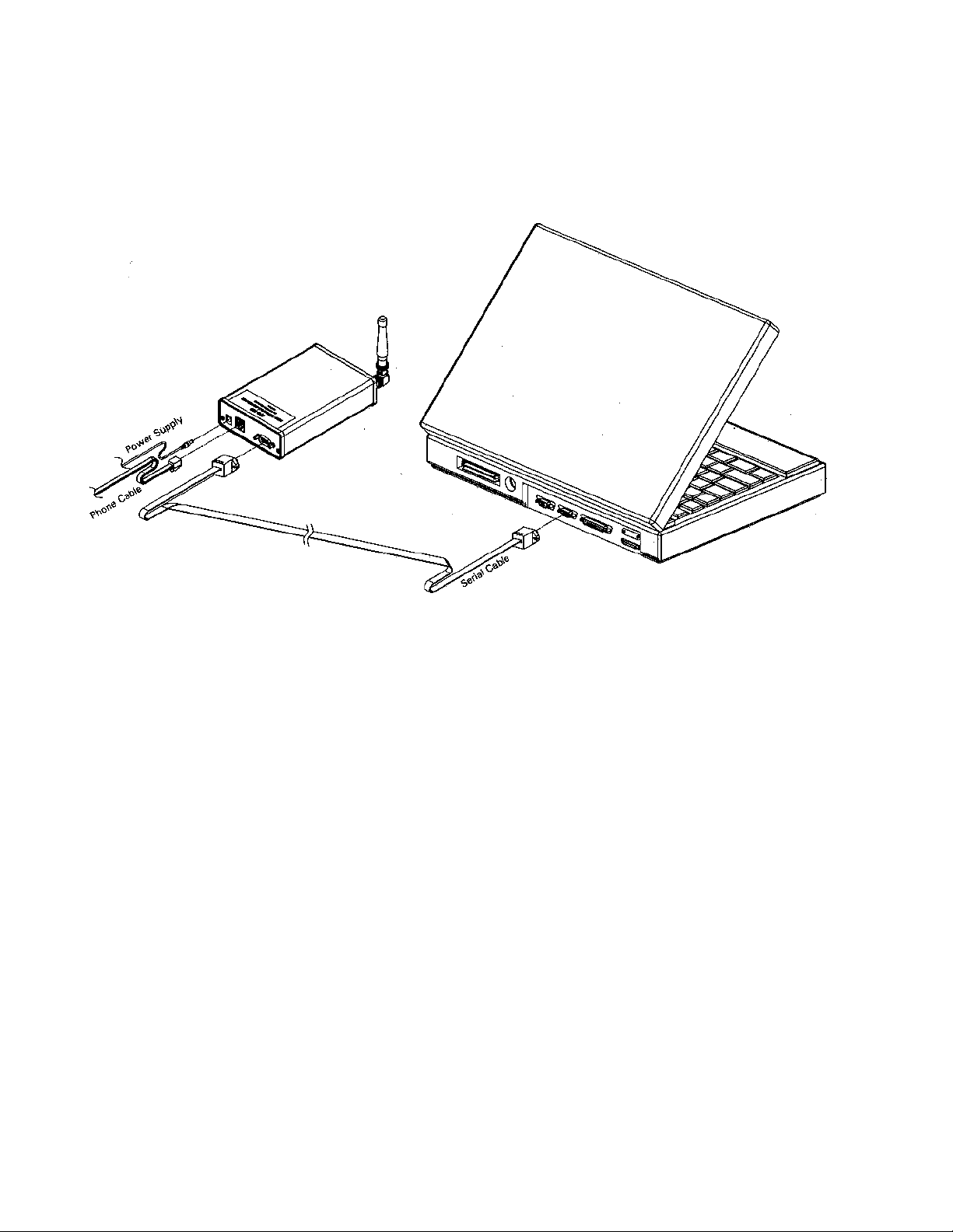
See Figure 5 for a visual representation of each component listed below.
• FPR-10 Interface Unit (Module Assembly) A3-06-2260
• Programming Head, PLB A3-06-2117
• Programming Head, RLB-32/33 A3-06-2119
• Serial Cable Assembly A3-06-2129
• 6 Conductor Cable with RJ11 plug (phone) A2-07-0137
• 240 VAC / 12v DC, 800 mA Euro Compatible A3-03-0263
Power supply
3.2 Check the Hardware and System Requirements
To run the FPR-10, you must have certain hardware and software installed on your
computer. The requirements include:
• Microsoft Windows 95 / 98 /, NT4.0, 2000 or ME.
• Pentium 75 MHz microprocessor (minimum).
• A hard disk with at least 10 megabytes of available storage.
• VGA or higher-resolution screen supported by Microsoft Windows.
• 16 megabytes of RAM.
• A mouse or other pointing device.
• 1 available serial port.
• Printer (optional)
4.0 INSTALLING THE FPR-100/10 SOFTWARE
The FPR-100/10 software may be downloaded from the web at
http://www.acrelectronics.com/download.html. The software is installed using the
setup program included on disk 1. The setup program will install all of the needed
files to your hard disk automatically. The software must be installed in the
C:\FPR100 directory to work correctly. This directory is the default directory in
the setup program.
1. Place the disk marked 1 of 4 into the floppy drive of your computer.
2. Click the START button on the bottom of your Windows operating system.
3. Type a:\setup.exe and press ENTER.
Y1-03-0164 Rev. A
Page 5

4
4. Choose the RUN option from the menu.
5. Follow the installation directions on the screen. The FPR-100/10 must be
installed in the “C:\Fpr100\” directory. This directory is already set when you
run the setup program.
6. Please refer to section 4.1 to set up your printer for use with the system.
4.1 Adding a Printer
1. Click the START button on the bottom of your Windows operating system.
2. Click the Settings option on the pop up menu.
3. Click the Printers option on the Settings menu.
4. From the Printers box that appears, click Add Printer and follow the
instructions. If you are using a computer purchased from ACR Electronics and
you are asked for the Windows disk, do the following:
A. When you get the message “Please insert the disk labeled ‘Windows 95
CD-ROM’ and then click OK” click the OK button.
B. There will then be an input box with the title Copying Files… In the space
provided under the Copy files from: type the following:
C:\Windows\Options\cabs then press ENTER.
C. If this does not work or if the computer cannot identify your printer, contact
the printer manufacturer for more information.
5. The printer, set up as your default printer, will be used by the FPR-10 for
printing labels and reports.
5.0 USING THE FPR-10
5.1 Programming the Message
The FPR-10 can program the Satellite2 406 RLB-32, RapidFix 406 RLB-33,
GlobalFix 406 RLB-35 and the GyPSI 406 PLB-100. Programming is
accomplished by generating the message in the computer with information based
on the unit and protocol selected. Data is then sent to the FPR-10 interface unit and
the interface unit handles all further communications with the beacons via infrared
light.
To program an RLB-32, RLB-33 or PLB, connect 6 Conductor Cable with RJ11
(phone) between the front panel of the FPR-10 and the appropriate programming
head. Perform the following steps:
1. From the Product Selection Menu, click the button for the product you wish to
program.
Y1-03-0164 Rev. A
Page 6

5
2. Click the model of the product you want to program, e.g. 2774 or 2775 for a
Satellite2 406. (you can find this information on the product label)
3. From the Option Selection Menu, click the Generate New Hex ID button.
4. Choose the Country you wish to program into the beacon by either typing the
name of the Country or scrolling to the Country. Once you have selected the
Country, press Enter or double click the mouse on the desired Country.
5. From the Protocol Selection Menu, click on the appropriate protocol. See
notes below for clarification of the different protocols.
6. When prompted, enter the value corresponding to the protocol chosen, e.g. if
serial protocol is chosen enter the appropriate serial number.
Note 1: MMSI is defined as the 9 digit ship identification number. It is the
country code followed by the ship's unique numeric identifier. If less than six
digits are entered, the FPR-10 automatically enters zeros in the beginning of the
value. For example, if the unique identifier is 123456 and you enter 12345, the
MMSI will be saved as 012345. There will be a warning from the PC if this
occurs before it is automatically saved.
Note 2: When programming a Maritime Call sign, the ranges of allowable call
sign prefixes are shown on the call sign entry page. These values are updated
periodically as different ranges are added. If you enter a value that is not in the
allowable range, there will be a warning displayed. If you are sure that the call
sign is valid for the beacon you are programming, just press the YES button
when asked if you want to continue.
Note 3: In some areas, the only change necessary to the GyPSI 406 PLB is
changing the serial number. There are 2 ways to recover the existing serial
number of the unit. The first way is on the hexadecimal identification label.
After the Unique Identifier Number (UIN) there is a dash and then a serial
number. This number is the present serial number in the unit.
If the label is defaced in any way there is a second way to recover the serial
number. Perform a Memory Read as described in section 5.3. The POS Message
Data that appears on the screen will indicate the existing serial number. This
number can then be used as the serial number for the PLB you are
programming. The ACR Message Data represents the initial serial number of
the beacon at the time of manufacture.
The above ways of recovering the existing serial number are only useful if there
are no rules for serialization for the country that the GyPSI 406 PLB will be
used. Check with your national authorities for any regulations governing the
serial numbers that can be encoded into the GyPSI 406 PLB and any other
beacon.
Y1-03-0164 Rev. A
Page 7

6
7. If MMSI, Maritime Call sign, or Radio Call sign are chosen, you will be
prompted to enter the EPIRB number after entering the protocol and its value.
For example, if the EPIRB being programmed is the only one, press ENTER.
This will be coded as beacon 1 of 1. However, if there are 3 beacons on the
ship and you are programming the second beacon, enter a 2 in the box
provided. Click OK after entering the value.
8. The message will be generated and the program will return to the Option
Selection Menu. All of the information entered and used to make the message
can be seen at the top of the screen.
9. Make sure the FPR-10 interface unit is connected to the PC with the serial cable
and properly powered up (see Figure 5). Also, make sure the programming
head is connected to the interface unit.
10. On the Option Selection Menu there is a button on the bottom right corner for
changing the serial port to which the FPR-10 is connected. The default is
COM1, which is normally a 9-pin connection. If you have connected the FPR10 interface unit to a different serial port, be sure to change it by clicking the
button and entering the new value.
11. From the Option Selection Menu, click the Program New Hex ID Into Unit
button.
12. A box will appear with the message to be sent to the beacon and the
communications port it will use for programming. If all of this information is
correct, click OK, or click CANCEL.
13. Once the PC has sent the information to the FPR-10 interface unit, the green
LED on the programming head will turn on and stay on for approximately 15
seconds.
14. Make sure the programming head is properly located on the Satellite2 406
beacon. See Figure 4 for positioning the programming head. The side of the
programming head with the LED should be directly over the LEDs on the
EPIRB.
15. Pull the test switch 1 time on the beacon.
16. There will be 2 short audible beeps from the EPIRB to indicate proper
programming. A message will also appear on the screen indicating the FPR-10
interface unit has sent the data through the programming head to the beacon.
To program an RLB-35, remove the connector from the front panel phone jack.
Note 4: An interlock prevents operation of the RLB-35 interface when the phone
jack is connected.
1. From the Product Selection Menu, click the GlobalFix 406 RLB-35.
2. Click the button of the model of the product you want to program, e.g. 2742 or
2744.
3. From the Option Selection Menu, Click the Generate New Hex ID button.
Y1-03-0164 Rev. A
Page 8

7
4. Choose the Country you wish to program into the beacon by either typing the
name of the Country or scrolling to the Country. Once you have selected the
Country, press Enter or double click the mouse on the desired Country.
5. From the Protocol Selection Menu, click on the appropriate protocol.
6. When prompted, enter the value corresponding to the protocol chosen, e.g. if
Serial protocol is chosen, enter the appropriate serial number.
7. The message will be generated and the program will return to the Option
Selection Menu. All of the information entered and used to make the message
can be seen at the top of the screen.
8. Make sure the FPR-10 interface unit is connected and properly powered up.
Also, make sure the beacon programming window is pointed in the direction of
the front of the interface unit and within 2 feet (60cm) of the interface unit. See
Figure 4.
9. From the Option Selection Menu, click the Program New Hex ID Into Unit
button.
10. There will be a box that will show the message to be sent to the beacon and the
communications port it will use for programming. If all of this information is
correct, click OK, or click CANCEL.
11. Once the PC has sent the information to the FPR-10 interface unit, the green
LED on the FPR-10 will turn on for approximately 15 seconds.
12. Make sure the beacon programming window is pointed toward the front panel
of the FPR-10.
13. Pull the test switch on the beacon once.
14. There will be two short audible beeps from the EPIRB to indicate proper
programming. A message will appear on the screen indicating the FPR-10
interface unit has sent the data.
If there are any problems with the communications between the FPR-10 interface
unit and the PC there will be a message that appears on the screen giving
information on the problem.
5.2 Printing Hexadecimal labels (UIN)
1. Program a new Hex ID into the beacon as described in section 5.1
2. On the Option Selection Menu click the Print Labels button.
3. Click the appropriate button for the top 4 or bottom 4 labels to be printed.
4. If the vessel name is known for the beacon, click the Enter Name of Vessel
button and enter the appropriate text.
5. Click the Click Here to Print Label button to print. The program uses the
printer that is set up as your default Windows printer.
Y1-03-0164 Rev. A
Page 9

8
5.3 Reading the Message
1. Make sure the FPR-10 interface unit is properly connected to the PC and
powered up (see Figure 5).
2. From the Product Selection Menu, click the GlobalFix 406 RLB-35.
3. From the Option Selection Menu, choose the Memory Read button.
4. A small message box appears with the instruction to Press OK, then put unit
into test mode. Click the OK button.
5. When performing a Memory Read for the Satellite2 406 RLB-32, RapidFix 406
RLB-33 or the GyPSI 406 PLB-100, a box appears with green text, Memory
Read Requested! Place programming head on beacon and pull test switch. At
this point, put the unit into test mode according to the manufacturer’s
directions. When performing a Memory Read for the GlobalFix 406 RLB-35,
the message displayed in green text shows Memory Read Requested! Point
beacon at the programming head and pull test switch. At this point, put the unit
into test mode according to the manufacturer’s directions.
6. Once the message has been sent back to the PC, the PC screen will display the
two beacon memory locations. See Figure 4. The first ACR message was
programmed at the factory and cannot be reprogrammed. The POS Message
Data is the message that will be transmitted by the beacon and may be modified
by following the Programming the Message procedure. If there is an ACR
message only, then that is the message that will be transmitted by the beacon.
When done viewing the message, click the OK button.
7. If the test is not performed in approximately fifteen seconds, the test will time
out. If this happens, go back to step 3 of this section and continue forward.
Y1-03-0164 Rev. A
Page 10

9
Figure 1 – Product Selection Menu
Y1-03-0164 Rev. A
Page 11

10
Figure 2 – Option Selection Menu
Y1-03-0164 Rev. A
Page 12

11
Figure 3 – Protocol Selection Menu
Figure 4 – Memory Read Display
Y1-03-0164 Rev. A
Page 13
12
Figure 5 – PC / FPR-100 Cable Connections
Y1-03-0164 Rev. A
Page 14

13
Figure 6 – Programming Head Positioning
Y1-03-0164 Rev. A
Page 15

14
Figure 7 – FPR-10 Hardware
Y1-03-0164 Rev. A
 Loading...