

Page 1

Technical Users Guide
Float Free 406
S-VDR Memory Capsule
Product No. 2515 Cat. 1
RLB-35MC
Y1-03-0202
Rev. E
FCC Type Accepted
Patent Pending
ACR Electronics, Inc.
5757 Ravenswood Road
Fort Lauderdale, FL 33312
Tel : +1 (954) 981-3333
Fax: +1 (954) 983-5087
www.acrartex.com
Email: info@acrartex.com
OWNER_____________________________
VESSEL_____________________________
RADIO CALL SIGN_____________________
Page 2

This page intentionally left blank
Y1-03-0202 Rev. E
Page 3

i
Table of Contents
1. Introduction ............................................................................................................................... 1
2. Specifications ............................................................................................................................. 1
3. Power-Over-Ethernet ............................................................................................................... 2
4. Connecting for Evaluation ....................................................................................................... 3
5. Evaluation Software Program ................................................................................................. 4
5.1. Purpose ................................................................................................................................. 4
5.2. Version Compatibility .......................................................................................................... 4
5.3. Setup .................................................................................................................................... 4
5.4. Test ....................................................................................................................................... 5
5.5. Data Upload Mode ............................................................................................................... 6
5.6. Data Download Mode .......................................................................................................... 7
5.7. Ship Configuration ............................................................................................................... 9
5.8. IP Address and Subnet Mask ............................................................................................. 10
6. Communications Command Structure ................................................................................. 11
6.1. Byte Definitions ................................................................................................................. 11
6.2. Header ................................................................................................................................ 12
6.3. Operation Command .......................................................................................................... 12
6.4. Operation Subcommand ..................................................................................................... 12
6.5. Reset Write Pointer ............................................................................................................ 13
6.6. CFC Size ............................................................................................................................ 13
6.7. CFC Magnitude .................................................................................................................. 13
6.8. Read Offset ........................................................................................................................ 13
6.9. Error Flags ......................................................................................................................... 13
6.10. Software Version ............................................................................................................. 14
7. Valid Commands ..................................................................................................................... 14
7.1. Write Port 7000: ................................................................................................................. 14
7.2. Read Port 7100:.................................................................................................................. 14
7.3. Status Port 7200: ................................................................................................................ 15
8. TCP/IP Communications Data Flow ..................................................................................... 16
9. TCP/IP Communications Data Write Example ................................................................... 17
10. TCP/IP Communications Data Read Examples................................................................. 18
10.1. Data Read All with Read Offset Example ....................................................................... 18
10.2. Data Read All without Read Offset Example .................................................................. 20
10.3. Data Read Example .......................................................................................................... 21
10.4. Read Status Memory Example ......................................................................................... 22
11. Ship Configuration................................................................................................................ 23
11.1. Data .................................................................................................................................. 23
11.2. Partition Size .................................................................................................................... 23
11.3. Write Ship Configuration Example ................................................................................. 24
11.4. Read Ship Configuration Example .................................................................................. 25
12. Data Integrity Flags .............................................................................................................. 26
12.1. Bit Definitions .................................................................................................................. 26
12.2. Status Request for Error Flag Word Example ................................................................. 27
12.3. Test Request for Error Flags, CFC Size, and Software Version Example ...................... 28
Y1-03-0202 Rev. E
Page 4

13. Change IP Address and Subnet Mask Command Structure ............................................ 29
13.1. Header .............................................................................................................................. 29
13.2. Operation Command ........................................................................................................ 29
13.3. Operation Subcommand................................................................................................... 29
13.4. New IP Address ............................................................................................................... 29
13.5. New Subnet Mask ............................................................................................................ 30
13.6. Setting a New IP Address and Subnet Mask Example .................................................... 31
© 2007 ACR Electronics, Inc. All rights reserved.
The copyright of this document is the property of ACR Electronics, Inc. This document is supplied
on the express terms that it is to be treated as confidential. No part of this document may be
reproduced or transmitted in any form or by any means, electronic or mechanical for any
purpose. The information in this document is subject to change.
ii Y1-03-0202 Rev. E
Page 5
1
S-VDR Computer RLB-35MC Capsule
10/100 Base-T Ethernet
Memory Card
4GB FLASH
8GB FLASH
Main Memory Storage
4,095 MBytes
8,190 MBytes
Ship Configuration Storage
1.0 MBytes
1.0 MBytes
IP Address
192.168.2.100 (Factory Default)
Port Numbers used
7000, 7100 and 7200
PoE Voltage
48 VDC
TCP/IP Data Rate
100Mbps
Ethernet Interface
Full Duplex
Power Requirement
8 Watts Max
Max CAT5 Cable Length
50 meters
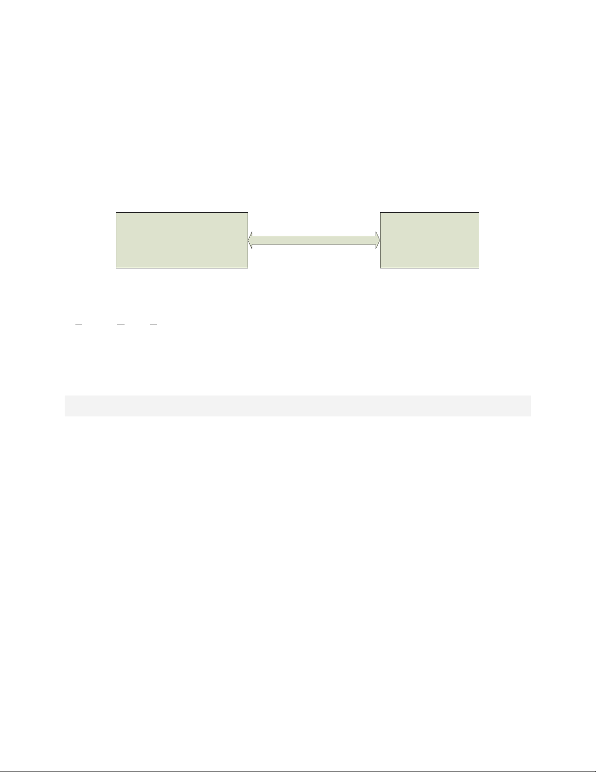
1. Introduction
The ACR Electronics RLB-35MC is an EPIRB containing a module with non-
volatile memory (FLASH) intended to store ship parameters from an S-VDR
in real time. The storage memory will continually store the last 12 hours or
more of received data. The interface between the S-VDR (Simplified Voyage
Data Recorder) and the memory capsule is with standard CAT-5 Ethernet
cable. Protocol is the standard TCP over IP or TCP/IP.
Power for the capsule is provided over the same Ethernet cable using PoE
(Power over Ethernet). This feature has the advantage in that a separate
power cable is not required.
2. Specifications
Y1-03-0202 Rev. E
Page 6
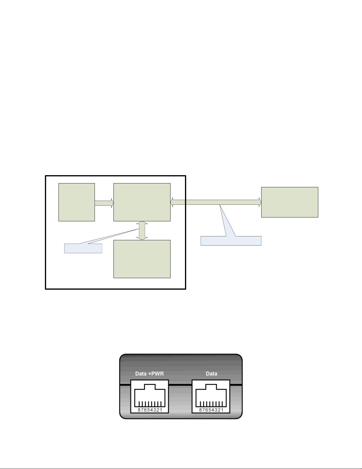
RLB-35MC Capsule
POE Power Injector
S-VDR Computer
+24 VDC
Power Supply
S-VDR System
Ethernet Data
Ethernet Data + Power
3. Power-Over-Ethernet
PoE technology brings power, as well as data transfer, to the RLB-35MC via
a standard twisted-pair Ethernet cable. In effect, PoE provides a new
standards-based way for a computer to provide power to a wide variety of
remote equipment in areas where it is physically or financially prohibitive to
offer normal power. The cost savings and reliability improvements involved
in not having to install and maintain power wiring in addition to Ethernet
cabling is especially a key factor onboard ships during an S-VDR installation.
The industry has standardized on the use of 48 VDC as the Injected PoE
voltage. The use of this higher voltage reduces the current flowing through
the CAT5 cable and therefore increases the load capability and increases the
CAT5 cable length limitations.
For evaluation and development, the RLB-35MC kit contains a power supply
which operates from AC power mains 100 – 250 VAC 50/60 cycle. Also
supplied are two CAT-5 cables for connecting between the power supply and
the RLB-35MC proto assembly. The other RJ-45 cable will connect to the
computer running the evaluation software.
2 Y1-03-0202 Rev. E
Page 7
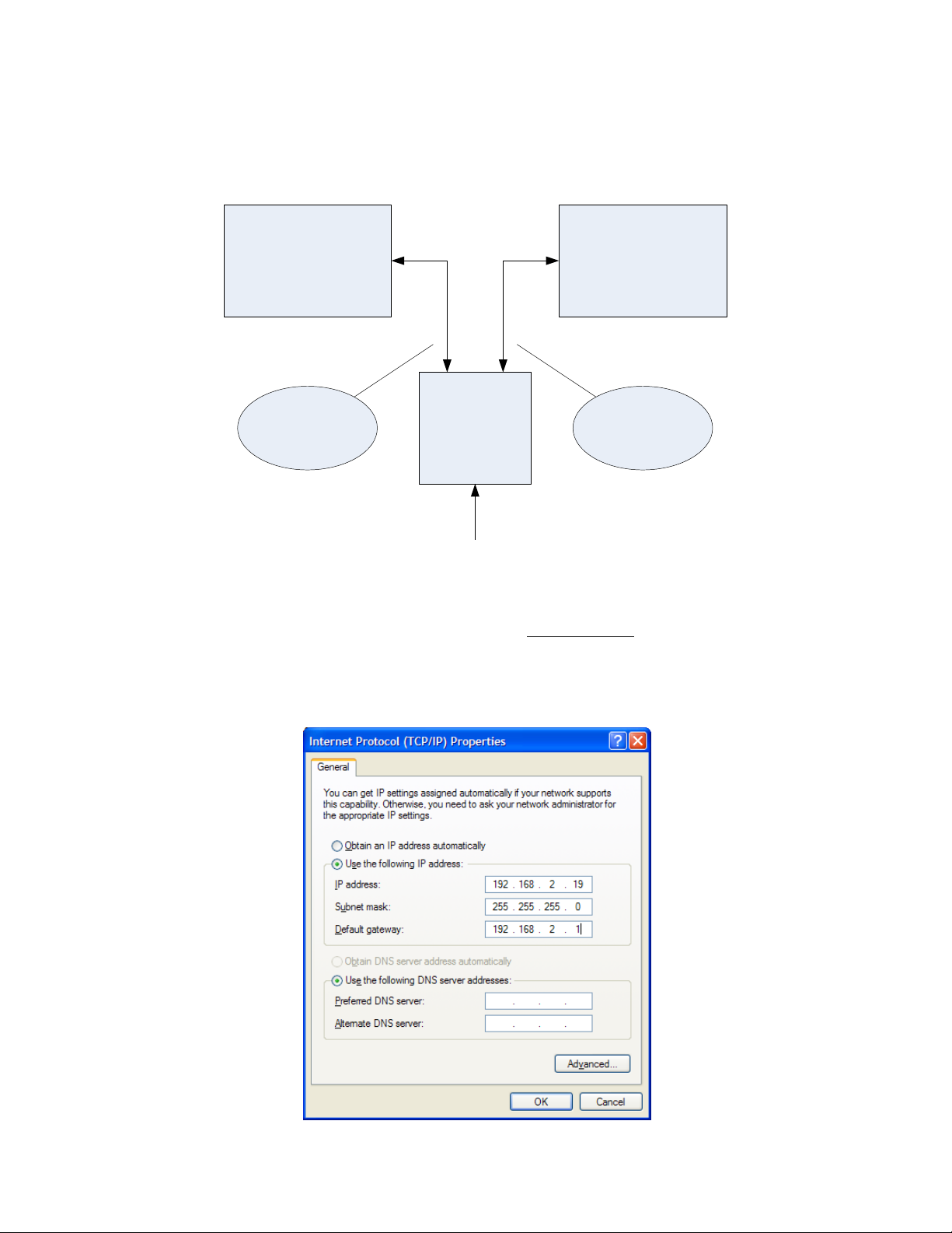
PC Testing Computer RLB-35MC
Power Supply
100-250 VAC 50/60 Cycle
DATA + PWRDATA
4. Connecting for Evaluation
Connect the RLB-35MC to a PC using the following illustration:
Either the cable between the PC and power supply or the RLB-35MC and
power supply will need to be a CAT-5 “cross-over” cable. The supplied
“green” cable included in the kit is a cross-over cable which can be used.
On the test PC, set the NIC TCP/IP address to 192.168.2.19.
3 Y1-03-0202 Rev. E
Page 8
5. Evaluation Software Program
5.1. Purpose
The RLB-35MC demo software is for evaluating the RLB-35MC only and
is not meant for use in actual VDR or S-VDR systems.
5.2. Version Compatibility
TCP_REC demo software versions 1.20 and higher have an option to
reset the capsule IP address and/or subnet mask; only RLB-35MC
Memory Board Software Version B and higher have this ability. The
demo software can still be used with the previous capsule software
version, but the capsule IP address and subnet mask can not be reset.
5.3. Setup
To load the RLB-35MC evaluation software on the testing PC, insert the
software CD and follow the installation instructions. This software uses
4 Y1-03-0202 Rev. E
Page 9
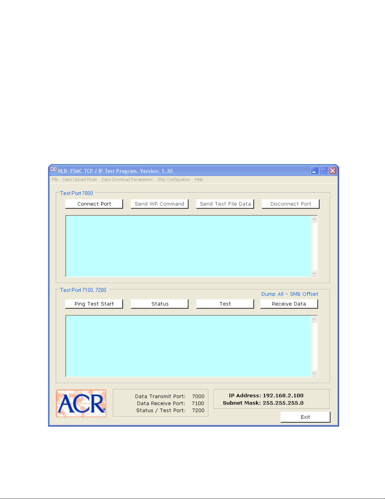
5.4. Test
the Microsoft .NET Framework so it may be necessary to download this
software from the Microsoft website if the test PC does not already
have the Framework software installed. Please note that our demo
software has not been tested on Windows Vista.
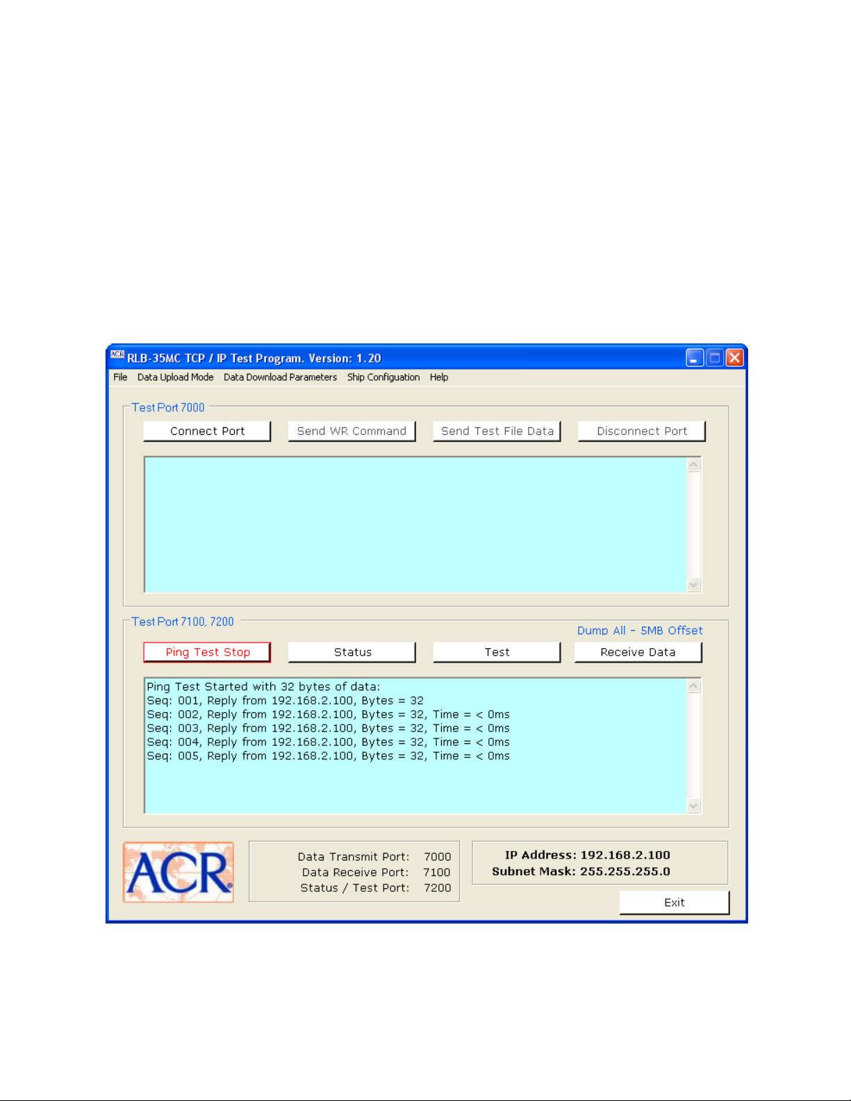
To begin, click the “Ping Test Start” button and confirm a successful
ping test in the Logging window. If the ping results display a fail
message, communications between the testing PC and the RLB-35MC
has not been established.
Once Ping is working correctly, click the Ping button again to stop the
ping test.
5 Y1-03-0202 Rev. E
Page 10
Next continue with the ‘Test’ and the ‘Status’ buttons and note the
results displayed in the logging text box where the ping results were
listed.
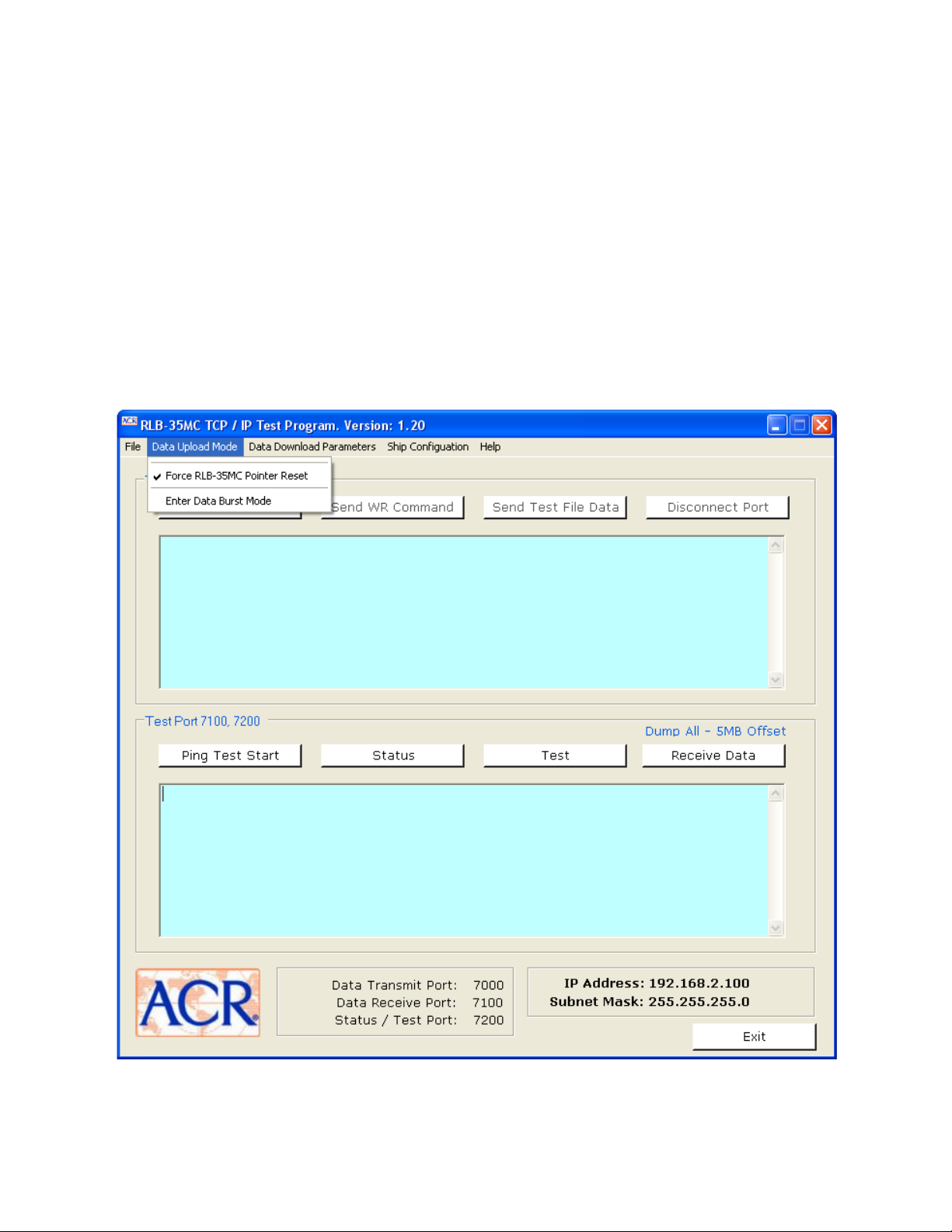
5.5. Data Upload Mode
Two options are available on the demonstration software for writing to
the Main Memory area. Select an upload option before connecting to
the port and writing a file into memory.
Select menu item “Data Upload Mode” and note the two options. When
selected a check mark appears to the left of the option.
6 Y1-03-0202 Rev. E
Page 11

Force RLB-35MC Pointer Reset.
This option will reset the current write location to the beginning of
Main Memory.
Note: To read back the data just written, choose the ‘Download from
beginning of memory to current write location’ option from the ‘RLB35MC Data Receive Setup’ window, then click the ‘Receive Data’
button. See the Demo Data Download Mode Section below.
Enter Data Burst Mode
This mode writes a file to the Main Memory area starting at the current
write location. Choose the ‘Enter Data Burst Mode’ from the ‘Data
Upload Mode’ pull-down menu.
Writing a File
After the upload mode is selected, click the ‘Send WR Command’. The
‘Send Test File Data’ can be selected repeatedly to write data to the
Main Memory. Each time this option is selected the user will be
prompted for the name of the file to write to memory. The current
write pointer is advanced each time data is written.
Disconnecting Port 7000
Clicking the ‘Disconnect Port’ button will disconnect the port.
5.6. Data Download Mode
Four options are available on the demonstration software for reading
data from the Main Memory area. Select the download mode before
reading data from memory.
Select menu item “Data Download Parameters” and note the four
options. When selected a dot appears in the circle to the left of the
option.
Download ALL capsule data
This option will read all of the Main Memory area starting at an address
that is the specified number megabytes ahead of the current write
location. Enter the desired number of megabytes for the offset.
Download Megabytes
This option will read a specified number of megabytes of Main Memory.
Enter the number of megabytes to read. The current write address
will be the last address to be read.
7 Y1-03-0202 Rev. E
Page 12
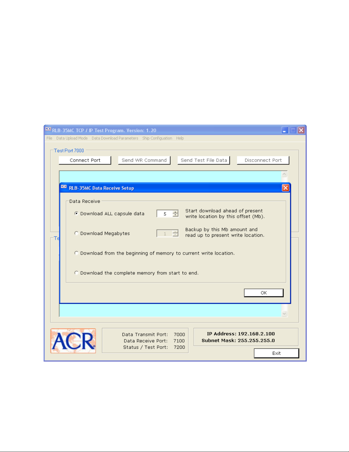
Download from the beginning of memory to current write location
This option reads the Main Memory area starting at the first address in
the partition and ending at the current write location. This can be
used to read back a compete file when used in conjunction with the
data upload option ‘Force RLB-35MC Pointer Reset’.
Download the complete memory from start to end
This option also reads all of the Main Memory area but starts at the
first address in the partition and ends at the last address.
Reading a File
After the download mode is selected, click the ‘Receive Data’ button.
Each time this option is selected the user will be prompted for the
name of a file to save the data to.
8 Y1-03-0202 Rev. E
Page 13
Disconnecting Port 7100
The port is automatically closed by the RLB-35MC after a read.
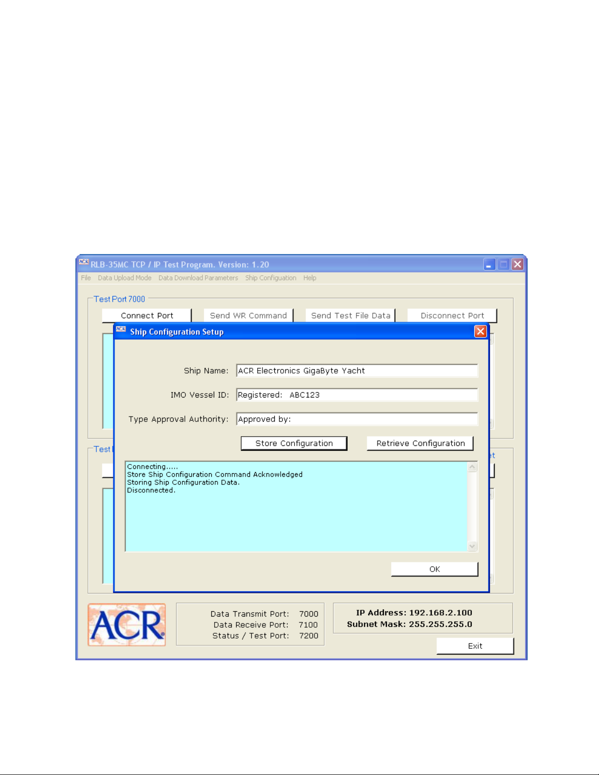
5.7. Ship Configuration
For evaluation, only a small amount of data is stored in the
Configuration Memory area. To access this area, click menu item ‘Ship
Configuration’ to open the following dialog window. To store the three
items, click on the ‘Store Configuration’ button. The data in the
windows can be modified if desired.
Click the ‘Retrieve Configuration’ button to read back what was
written.
9 Y1-03-0202 Rev. E
Page 14

5.8. IP Address and Subnet Mask
Setting a New IP Address and Subnet Mask
To change the IP address or subnet mask, click menu item ‘File’ then
click ‘Configure Capsule IP Address and Subnet Mask’ to open the
following dialog window.
Change the IP address and/or subnet mask and click the ‘Save’ button.
The IP address and subnet mask displayed in the lower right corner of
the demo software screen will display the new values. Cycle the
power to the RLB-35MC Memory Board for the new values to take
effect.
10 Y1-03-0202 Rev. E
Page 15
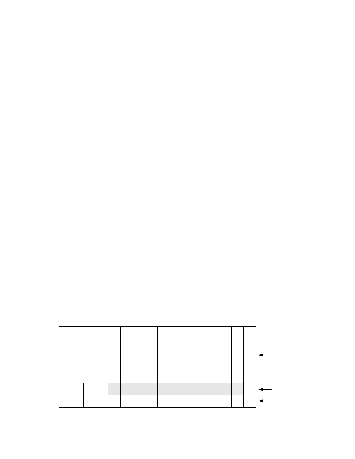
AC 53 CA 35 00
Fixed Command Header
Operation Command
Operation Subcommand
Reset Write Pointer
CFC Size MSB
CFC Size LSB
CFC Size Magnitude
Read Offset MSB
Read Offset LSB
Status Flags MSB
Status Flags LSB
Software Version
Termination
0 1 2 3 4 5 6 7 8 9 10 11 12 13 14 15
byte
value
command
Forcing the IP Address and Subnet Mask Back to the Default Values
To force the RLB-35MC Memory Board back to its default state with no
user set values in effect and with the default IP address of
192.168.2.100 and subnet mask of 255.255.255.0 reinstated, do the
following:
1. Remove power from the Memory Board.
2. Remove the CFC from its holder.
3. Apply power to the Memory Board with the CFC still removed.
4. Wait 10 seconds.
5. Remove power from the Memory Board.
6. Re-engage the CFC in its holder.
7. Re-apply power to the Memory Board. The default values are now
in effect.
8. On the PC edit the IP Address and IP Subnet Mask in the RLB-35MC
TCP_REC registry back to the default values. To get to the registry
editor select ‘Run’ on the windows startup menu, then type in
regedit and click ok. Next select the RLB-35MC TCP_REC program
from the list on the left-hand side of the Registry Editor window;
the list of RLB-35MC TCP_REC registers available will come up on
the right-hand side of the Registry Editor window.
6. Communications Command Structure
6.1. Byte Definitions
The RLB-35MC is configured as an iterative server with the PC as a
client. The RLB-35MC server will be looking for a command string
defining the requested operation as received from the client. The
command string is sixteen (16) bytes in length with fixed byte
positions defining various functions as seen below:
11 Y1-03-0202 Rev. E
Page 16

ASCII
Character
Hex
Value
Command
R
0x52
If main memory, read the read offset specified number MB of data, else
read & return all the data from the specified memory partition.
W
0x57
Write into the specified memory partition
D
0x44
Read all of main memory starting at the specified read offset from the
current write address and ending at the address just before the stating
address
P
0x50
Read main memory from the partition’s beginning address to the current
write address
F
0x46
Read all of main memory starting at the partition’s beginning address to
the ending address
S
0x53
Request the memory board status
E
0x45
Request the memory board status, CFC size, & software version
ASCII
Character
Hex
Value
Definition
0
0x30
Test status request
1
0x31
Main memory partition
2
0x32
Configuration memory partition
3
0x33
Status memory partition
Bytes 0 – 6, 10, and 11 are part of the command string sent by the
user to the RLB-35MC Memory Board. Bytes 7 – 9 and 12 – 14 are
returned by the RLB-35MC Memory Board with the echoed command
string in response to a ‘Test’ command (‘E’ command and ‘0’
subcommand); only bytes 12 and 13 are returned with the command
string in response to a ‘Status’ command (‘S’ command).
6.2. Header
The first four (4) bytes are a fixed value header with hexadecimal
values of AC, 53, CA, 35.
6.3. Operation Command
Byte 4 is the Operation Command and is in ACSII format:
6.4. Operation Subcommand
Byte 5 is the Operation Subcommand, and is in ASCII format. It
defines which partition of memory each read or write command will
operate on.
12 Y1-03-0202 Rev. E
Page 17

Decimal
Number
Hex
Value
Definition
0
0x00
Do not reset the current write address pointer of the specified memory
partition.
1
0x01
Reset the current write address pointer of the specified memory partition to
the first address in the partition.
ASCII
Character
Hex
Value
Definition
G
0x47
Gigabytes
M
0x4D
Megabytes
Command
Subcommand
Read Offset Definition
‘R’
‘1’
The read offset gives the number of MB behind the current write
address to start reading.
‘D’
‘1’
The read offset gives the number MB ahead of the current write
address to start reading.
15 14 13 12 11 10 9 8 7 6 5 4 3 2 1 0
FRAM
Spare
Spare
Spare
Spare
CFC Data
CFC Communications
FRAM
CFC Missing
SDRAM
SRAM
CPU
byte
bit
error flag
Spare
Spare
Spare
Spare
12 13
6.5. Reset Write Pointer
6.6. CFC Size
Bytes 7 and 8 indicate the CFC size in gigabytes or megabytes as a
decimal number.
6.7. CFC Magnitude
Byte 9 is in ASCII format and indicates either gigabytes or megabytes:
6.8. Read Offset
Bytes 10 and 11 are the read offset in number of megabytes as a
decimal number; the read offset is defined for the following
command/subcommand combinations:
6.9. Error Flags
Bytes 12 and 13 are the error flags, the bits are defined below:
Note that all the Error Flags are 0 = PASS and 1 = FAIL except for bit 3, the CFC Missing flag,
where 0 = card present and 1 = card missing.
13 Y1-03-0202 Rev. E
Page 18

W 1 xx200100100100100100100
1
Operation Command
Operation Subcommand
Reset Write Pointer
CFC Size MSB
CFC Size LSB
CFC Size Magnitude
Read Offset MSB
Read Offset LSB
Status Flags MSB
Status Flags LSB
W 2 00100100100100100100100
1
Write received data into main memory starting at the current write address
Write received data into configuration memory starting at the current write address
Definition
1)
2)
0x00 = leave the current write address as is; 0x01 = reset the current write address to the first address in the memory partition
Don’t Cares
00
1
Software Version
00
1
R 1 001001001001xx2xx200100
1
Operation Command
Operation Subcommand
Reset Write Pointer
CFC Size MSB
CFC Size LSB
CFC Size Magnitude
Read Offset MSB
Read Offset LSB
Status Flags MSB
Status Flags LSB
R 2 00100100100100100100100
1
R 3 00100100100100100100100
1
D 1 001001001001xx3xx300100
1
P 1 00100100100100100100100
1
F 1 00100100100100100100100
1
1)
2)
3)
Read main memory starting at the address that is the number of offset MBs behind the current
write address and ending at the last address written at the time the command was received.
Read configuration memory starting at the first address and ending at the last address written at
the time the command was received.
Read status memory starting at the first address and ending at the last address written at the time
the command was received.
Read all of main memory starting at the address the number of offset MBs ahead of the current
write address and ending at the address one less than the read starting address.
Read all of main memory starting at the first address in the partition and ending at the last address
written at the time the command was received.
Read all of main memory starting at the first address in the partition and ending at the last valid
address in the partition.
Definition
Number of MBs offset ahead of the current write position to start reading all of main memory
Number of MBs of main memory to read behind the current write position
Don’t Cares
00
1
Software Version
00
1
00
1
00
1
00
1
00
1
6.10. Software Version
Byte 14 is in ASCII format and indicates the RLB-35MC Memory
Board’s software version.
7. Valid Commands
The possible valid combinations during normal VDR operations are as
follows:
7.1. Write Port 7000:
RLB-35MC Write Commands
7.2. Read Port 7100:
14 Y1-03-0202 Rev. E
RLB-35MC Read Commands
Page 19

Command
Sub-Command
Offset Megabytes
“D”
“1”
0007
Command
Sub-Command
Offset Megabytes
“R”
“1”
000E
S 00100100100100100100100100
1
Operation Command
Operation Subcommand
Reset Write Pointer
CFC Size MSB
CFC Size LSB
CFC Size Magnitude
Read Offset MSB
Read Offset LSB
Status Flags MSB
Status Flags LSB
E 30200100100100100100100100
1
1)
Request the memory board status
Request the memory board status, CFC size, and software version
Definition
Don’t Cares
2)
Must be ASCII zero, 0x30
00
1
Software Version
00
1
When reading (dumping) all of Main Memory data out of the RLB-35MC
two commands are available. The ‘D’ command with a 16-bit offset
value represents the number of megabytes ahead of the current
writing position to start reading. For example, if the read offset is 7 MB
and the current write address is 0x2110, the data dump would begin
at 0x2117. All of Main Memory’s data would be read ending with the
last read at address 0x2116. If the ‘F’ command is used the data will
be read back from the first address in the Main Memory partition to the
last address in the partition.
RLB-35MC Dump with OFFSET
When reading Main Memory data out of the RLB-35MC, an offset value
is made available so that only a portion of the data can be retrieved.
The offset value in this case is the number of megabytes to read. The
read starts at a location the specified number of megabytes behind the
current write position and ends at the write location at the time the
command was received. For example, a download of data that was
stored 14 megabytes ago would be:
A read command to the Configuration Memory reads back the entire
Configuration Memory that was written. A read command to the
Status Memory reads back the data stored in the Status Memory area.
7.3. Status Port 7200:
15 Y1-03-0202 Rev. E
RLB-35MC Read with OFFSET
RLB-35MC Status Requests
Page 20

Client RLB-35MC
Client request a data store in main and sends command
AC,53,CA,35,57,31,00,00,00,00,00,00,00,00,00,00
Client receives the write command back and confirms it
with it’s original request. If confirmed, client starts
sending data to the RLB-35MC.
RLB-35MC receives the write request. Identifies it as a
valid command and re-sends the command back
AC,53,CA,35,57,31,00,00,00,00,00,00,00,00,00,00
RLB-35MC receives the clients data stream and stores
all data in the main partition.
Time .
When requesting the RLB-35MC Memory Board status, two commands
are available; both the ‘S’ and ‘E’’0’ command return the command
with the error flags set as necessary, additionally the ‘E’’0’ command
returns the CFC size and software version.
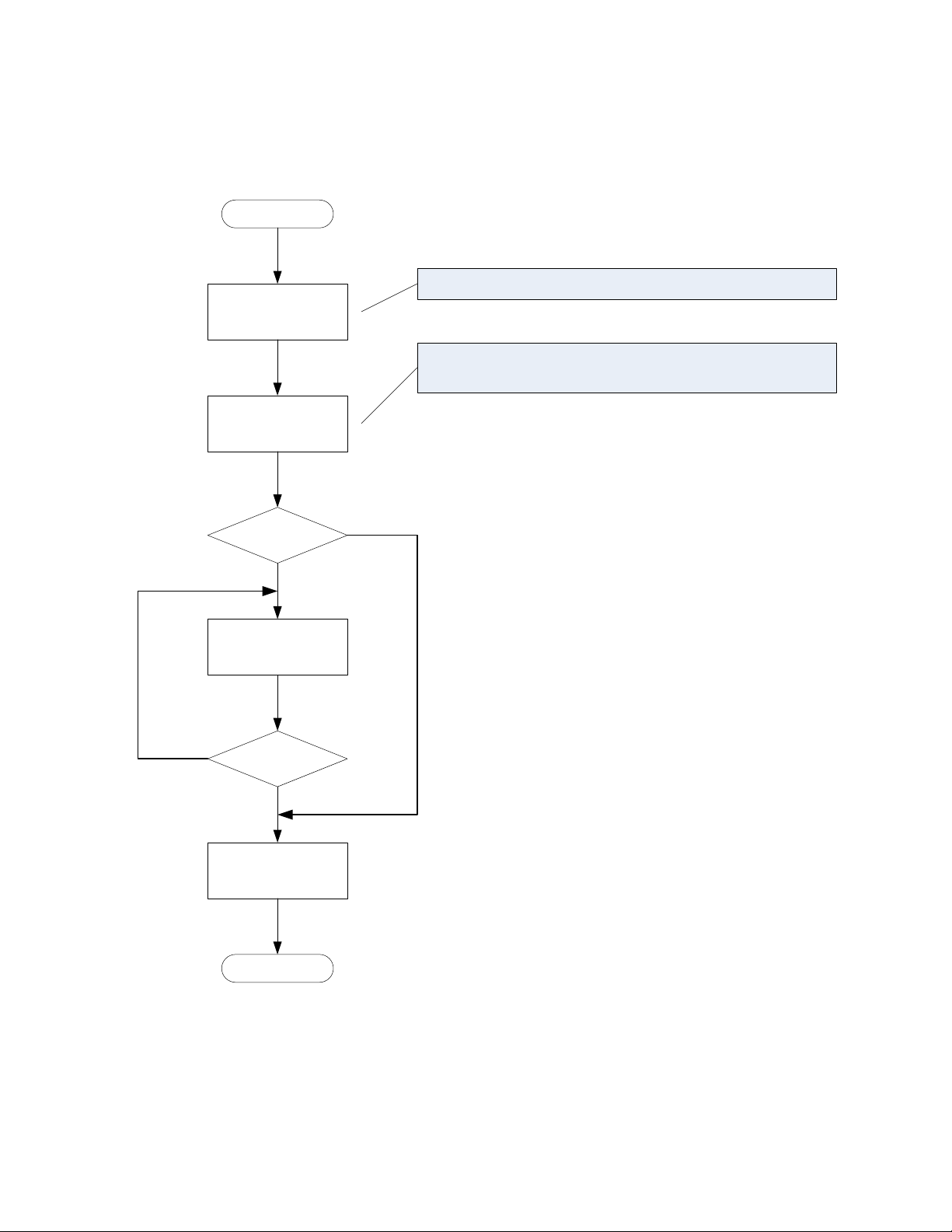
8. TCP/IP Communications Data Flow
Once the command is sent to the RLB-35MC, confirmation will be returned
back to the client as an “echo” of the initial 16 byte command. This will
insure that both the server and the client are in agreement as to what the
command is and the correct follow-through of that command. For example,
if we send a command to write data into the main data partition:
16 Y1-03-0202 Rev. E
Page 21

Send write command
to RLB-35MC
Start
Command echoed
back?
Send data packet to
RLB-35MC
End of data?
Close socket
connection
End
Yes
No
No
Yes
Open socket
Connection on Port
7000
Write data into main data partition.
AC,53,CA,35,57,31,00,00,00,00,00,00,00,00,00,00
All write commands are on port 7000.
9. TCP/IP Communications Data Write Example
See section 5.3 for how to execute this sequence using our demo software.
17 Y1-03-0202 Rev. E
Page 22

Send command
to RLB-35MC
Start
Command echoed
back?
Read data packet from
RLB-35MC
RLB-35MC closed
socket?
Close socket
connection
End
Yes
No
No
Yes
Open socket
Connection on Port
7100
Read ALL data from main data partition with a read offset
AC,53,CA,35,44,31,00,00,00,00,00,05,00,00,00,00
All read commands are on port 7100.
10. TCP/IP Communications Data Read Examples
10.1. Data Read All with Read Offset Example
Note that this is the ‘Download ALL capsule data’ option in the ‘RLB35MC Data Receive Setup’ window, with 5 MB entered as the read
offset.
18 Y1-03-0202 Rev. E
Page 23
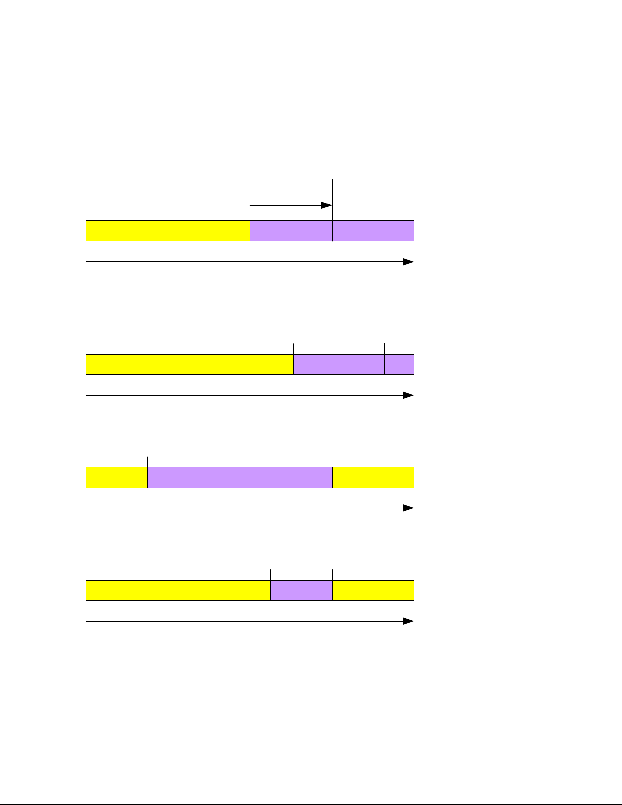
New Data Old Data
Write
Pointer
Read
Pointer
Pointer Advancement
5Mb Offset
Snapshot of the Read
Pointer Address is captured.
New Data Old Data
Write
Pointer
Read
Pointer
Pointer Advancement
Pointers advanced during a
read and write condition.
New Data Old Data
Write
Pointer
Read
Pointer
Pointer Advancement
Pointers “wrap around” when
reaching top of memory..
New Data
New Data Old Data
Write
Pointer
Read
Pointer
Pointer Advancement
Read pointer is equal to the
snapshot address at the
begin of read. Read exits and
disconnects the port.
New Data
Data read all download with offset example (continued)
19 Y1-03-0202 Rev. E
Page 24

Send command
to RLB-35MC
Start
Command echoed
back?
Read data packet from
RLB-35MC
RLB-35MC closed
socket?
Close socket
connection
End
Yes
No
No
Yes
Open socket
Connection on Port
7100
Read ALL data from main data partition from begin to end.
AC,53,CA,35,46,31,00,00,00,00,00,00,00,00,00,00
All read commands are on port 7100.
10.2. Data Read All without Read Offset Example
Note that this is the ‘Download the complete memory from start to
end’ option in the ‘RLB-35MC Data Receive Setup’ window.
20 Y1-03-0202 Rev. E
Page 25

Send command
to RLB-35MC
Start
Command echoed
back?
Read data packet from
RLB-35MC
Socket closed?
Close socket
connection
End
Yes
No
No
Yes
Open socket
Connection on Port
7100
Read back 330MB of data from main data partition.
AC,53,CA,35,53,31,00,00,00,00,01,4A,00,00,00,00
Note: 330 = 0x14A
All read commands are on port 7100.
10.3. Data Read Example
Note that this is the ‘Download Megabytes’ option in the RLB-35MC
Data Receive Setup window, with 330 MB entered as the number of
megabytes to read.
21 Y1-03-0202 Rev. E
Page 26

Send command to
RLB-35MC
Start
Command echoed
back?
Read data packet from
RLB-35MC
Socket closed?
Close socket
connection
End
Yes
No
No
Yes
Open socket
Connection on Port
7100
Read Status Memory.
AC,53,CA,35,52,33,00,00,00,00,00,00,00,00,00,00
All read commands are on port 7100
10.4. Read Status Memory Example
Note that our demo software does not demonstrate this option.
22 Y1-03-0202 Rev. E
Page 27

11. Ship Configuration
11.1. Data
An area of data defining the configuration of the S-VDR and the
sensors is written into the final recording medium during
commissioning of the S-VDR. This configuration data is permanently
retained in the final recording and protected from modification other
than by a duly authorized person. Changes to the configuration data
block does not affect the normal recording of the mandatory items.
IEC-61996-2 defines the following system configuration information
and data source which shall be included in this data block:
a) Type approval authority and reference.
b) IMO vessel identification number.
c) Software version(s) used.
d) Microphone locations and recording port allocation.
e) VHF communications – which VHF channel(s) are being recorded.
f) Date and time – from which source obtained.
g) Ship’s position – from which EPFS obtained and position on the vessel.
h) Other data inputs – Identifying other inputs.
i) Automatic insertion of date and time of last amendment.
11.2. Partition Size
The RLB-35MC reserves 1MB of protected memory for storing the ship
configuration.
23 Y1-03-0202 Rev. E
Page 28
Send write command
to RLB-35MC
Start
Command echoed
back?
Send data packet to
RLB-35MC
End of data?
Close socket
connection
End
Yes
No
No
Yes
Open socket
Connection on Port
7000
Write data into ship configuration partition.
AC,53,CA,35,57,32,00,00,00,00,00,00,00,00,00,00
All write commands are on port 7000.
11.3. Write Ship Configuration Example
Note that this is the ‘Store Configuration’ option on our demo
software’s ‘Ship Configuration Setup’ menu.
24 Y1-03-0202 Rev. E
Page 29

Send command to
RLB-35MC
Start
Command echoed
back?
Read data packet from
RLB-35MC
Socket closed?
Close socket
connection
End
Yes
No
No
Yes
Open socket
Connection on Port
7100
Read Ship Configuration Memory.
AC,53,CA,35,52,32,00,00,00,00,00,00,00,00,00,00
All read commands are on port 7100
11.4. Read Ship Configuration Example
Note that this is the ‘Retrieve Configuration’ option on our demo
software’s ‘Ship Configuration Setup’ menu.
25 Y1-03-0202 Rev. E
Page 30

AC 53 CA 35 00
Fixed Command Header
(HEX)
Operation Command
Operational Sub Command
Reset Write Pointer
CFC Size MSB
Null Termination 0x00
CFC Size LSB
CFC Size Magnitude
Offset MSB
Offset LSB
Status Flag MSB
Status Flag LSB
00
Software Version
Termination
RLB-35MC Command Structure
0 1 2 3 4 5 6 7 8 9 10 11 12 13 14 15 Offset
Status Flag word (LSB)
Status Flag word (MSB)
0 = Normal Status
53 00
Bit Position
Error Flag Definition Bytes 12 & 13
0
CPU Test
1
Internal Static RAM
2
External Dynamic RAM
3
Compact Flash Card Missing
4
Ferrite RAM (NVRAM)
5
Compact Flash Card Communications
6
Compact Flash Card Data Bad
7 - 15
Not Assigned
12. Data Integrity Flags
12.1. Bit Definitions
Bytes within the command string at offset location 12 and 13 make up
a 16 bit status flag. This 16 bit word can be monitored to determine if
there are any failures or data integrity problems within the RLB-35MC
capsule. If the flag word is at 0x0000, no fail reports have been
detected. A non-zero flag word would mean a failure has been
detected.
During normal operation port 7200 can be opened to request the
beacon’s error status at any time. When the command word is echoed
back, check for a non-zero flag word to detect any errors.
The error flags are returned in response to both the ‘S’ command and
the ‘E’ command with a ‘0’ subcommand. The CFC size and software
version are also returned for the ‘E’ command with a ‘0’ subcommand.
26 Y1-03-0202 Rev. E
Page 31

Send Status Request
command
to RLB-35MC
Start
Command echoed
back?
Read data packet from
RLB-35MC
Flag Word = 0?
Close socket
connection
End
Yes
No
No
Yes
Open socket
Connection on Port
7200
Read Error Flag Word only.
AC,53,CA,35,53,00,00,00,00,00,00,00,00,00,00,00
Status request is on port 7200
RLB-35MC Fail
12.2. Status Request for Error Flag Word Example
Note that the ‘Status’ button of the demo software demonstrates this
command. The error flags are returned in response to this command.
27 Y1-03-0202 Rev. E
Page 32

Send Test Request
command
to RLB-35MC
Start
Command echoed
back?
Read data packet from
RLB-35MC
Flag Word = 0?
Close socket
connection
End
Yes
No
No
Yes
Open socket
Connection on Port
7200
Read Error Flag Word, CFC Size, and Software Version.
AC,53,CA,35,45,30,00,00,00,00,00,00,00,00,00,00
Test request is on port 7200
RLB-35MC Fail
12.3. Test Request for Error Flags, CFC Size, and Software Version Example
Note that the ‘Test’ button of the demo software demonstrates this
command. The error flags, CFC size, and software version are returned in
response to this command.
28 Y1-03-0202 Rev. E
Page 33

yy2yy2yy2yy
2
AC 53 CA 35 xx1xx
1
Fixed Command Header
(HEX)
Operation Command
Operational Sub Command
New IP Address MSB
New IP Address 3
rd
Byte
Null Termination 0x00
xx1xx
1
New IP Address 2
nd
Byte
New IP Address LSB
Subnet Mask MSB
Subnet Mask 3
rd
Byte
Subnet Mask 2
nd
Byte
Subnet Mask LSB
00 00
Null
Termination
RLB-35MC Command Structure
0 1 2 3 4 5 6 7 8 9 10 11 12 13 14 15
Byte
49 50
1)
2)
The new subnet mask with the MSB of the 4-byte mask in byte 10 and the LSB in byte 13
The new IP address with the MSB of the 4-byte address in byte 6 and the LSB in byte 9
Byte
Position
Decimal Notation
Hex Notation
6
192
0xC0
7
168
0xA8
8 2 0x02 9 75
0x4B
13. Change IP Address and Subnet Mask Command Structure
The RLB-35MC’s IP address and subnet mask can be changed from the
factory set default values of 192.168.2.100 and 255.255.255.0, respectively,
in RLB-35MC Memory Board Software Version B and higher. The command
string is sixteen (16) bytes in length and has the same fixed command
header as the communications command string. The bytes are defined as
seen below:
13.1. Header
The first four (4) bytes are a fixed value header with hexadecimal
values of AC, 53, CA, 35.
13.2. Operation Command
Byte 4 is the Operation Command of ‘I’ in ACSII format.
13.3. Operation Subcommand
Byte 5 is the Operation Subcommand of ‘P’ in ASCII format.
13.4. New IP Address
Bytes 6 – 9 are the new IP address arranged so the MSB of the 4-byte
IP address is in byte 6 and the LSB is in byte 9. Below is an example
of a new IP address of 192.168.2.75:
29 Y1-03-0202 Rev. E
Page 34

Byte
Position
Decimal Notation
Hex Notation
10
255
0xFF
11
255
0xFF
12
255
0xFF
13
252
0xFC
13.5. New Subnet Mask
Bytes 10 – 13 are the new subnet mask arranged so the MSB of the 4byte subnet mask is in byte 10 and the LSB is in byte 13. Below is an
example of a new subnet mask of 255.255.255.252:
Note that the subnet mask should be sent with the IP address even if
only the IP address is being changed.
30 Y1-03-0202 Rev. E
Page 35

Send Set IP Address &
Subnet Mask request
to RLB-35MC
Start
Command echoed
back?
Setting IP Address &
Subnet Mask Failed
Close socket
connection
End
No
Yes
Open socket
Connection on Port
7200
Set IP Address & Subnet Mask.
AC,53,CA,35,49,50,C0,A8,02,4B,FF,FF,FF,00,00,00
Set IP Address & Subnet Mask request is on port 7200
Setting IP Address &
Subnet Mask was
Successful
The above example is for an IP Address of 192.168.2.75
and a Subnet Mask of 255.255.255.0.
13.6. Setting a New IP Address and Subnet Mask Example
Note that this is the ‘Configure Capsule IP Address and Subnet Mask’ option
in our demo software. To make the new settings take effect, cycle power to
the RLB-35MC capsule.
31 Y1-03-0202 Rev. E
 Loading...