

Page 1
0
OWNER_____________________________
VESSEL_____________________________
RADIO CALL SIGN_____________________
Page 2
ii
CAUTION: Before proceeding to install, test or use your new ACR Electronics’ product, please
read this Product Support Manual in its entirety.
If you have questions regarding the contents of the manual, please contact our Technical Service
Department at ACR Electronics, Inc., Telephone +1 (954) 983- 3333. Please be ready to provide the
technician with the page number you wish to discuss. If you have a question that is not covered in the
manual, please visit our website and access the Frequently Asked Questions (FAQs) section for further
information or call our Technical Services Department. The website address is
www.acrelectronics.com. If in the future you lose this manual, you may access and print a replacement
on the ACR website.
Page 3

ii
PLEASE READ ALL WARNINGS, CAUTIONS AND
NOTES CAREFULLY
FOREWORD
Congratulations and thank you for purchasing the ACR Memory capsule. The combination of superior design, high
quality raw materials and quality controlled manufacturing produce a product that will perform for years to come. The
test facility at ACR can reproduce some of the harshest environmental conditions known to man. This assures that the
products we produce can stand up to the rigors found in a marine environment. With proper care and maintenance,
your MEMORY CAPSULE will be in service for years to come.
ACR is proud to be certified to the ISO 9001:2000, the International Organization for Standardization.
This manual provides installation, operation and maintenance instructions for the Float Free 406 Memory Capsule,
hereinafter referred to as the memory capsule. This manual also describes the characteristics and details of the
Memory capsule System. S-VDR carriage requirements are contained in IMO regulations.
TABLE OF CONTENTS
SECTION 1 - REGISTRATION OF 406 MHZ MEMORY CAPSULES ............................................................................. 1
1.1 Why is registration important? ......................................................................................................................... 1
1.2 What country should I register in? ................................................................................................................... 2
1.3 How do I register? .............................................................................................................................................. 2
1.4 Do I need a radio license? ................................................................................................................................. 2
1.5 Change of Ownership or Contact Information ................................................................................................ 3
1.6 Commercial Vessels Worldwide ....................................................................................................................... 3
1.7 Lost or Stolen Memory Capsules ..................................................................................................................... 3
SECTION 2 – PRODUCT FEATURES ............................................................................................................................. 3
2.1 Memory Storage System.................................................................................................................................... 3
SECTION 3 - FALSE ALARMS ........................................................................................................................................ 6
3.1 Prevention of False Alarms ............................................................................................................................... 6
3.2 Reporting of False Alarms ................................................................................................................................. 6
SECTION 4 - INSTALLATION / ASSEMBLY ................................................................................................................... 6
4.1 Mounting Location ............................................................................................................................................. 6
4.2 Assembling your Float Free Memory Capsule ................................................................................................ 8
4.3 Visual Inspection .............................................................................................................................................. 12
4.4 Important Expiration Dates.............................................................................................................................. 12
SECTION 5 - OPERATION ............................................................................................................................................. 13
5.1 General .............................................................................................................................................................. 13
5.2 Automatic Deployment and Activation .......................................................................................................... 13
5.3 Manual Deployment and Activation ................................................................................................................ 14
5.4 Deactivation ...................................................................................................................................................... 14
5.5 Full Functional Self Test .................................................................................................................................. 14
5.6 Internal GPS Test .............................................................................................................................................. 15
SECTION 6 - CARE AND MAINTENANCE .................................................................................................................... 16
SECTION 7 - THE SEARCH AND RESCUE SYSTEM .................................................................................................. 17
7.1 General Overview ............................................................................................................................................. 17
7.2 Satellite Detection ............................................................................................................................................ 17
7.3 Global Positioning System (GPS) ................................................................................................................... 17
SECTION 8 - AUTHORIZATIONS .................................................................................................................................. 19
8.1 Approvals .......................................................................................................................................................... 19
8.2 Characteristics .................................................................................................................................................. 19
8.3 Technical Data - memory capsule .................................................................................................................. 19
8.4 Specifications ................................................................................................................................................... 19
8.5 Accessories ...................................................................................................................................................... 20
SECTION 9- WARRANTY .............................................................................................................................................. 21
9.1 Limited Warranty .............................................................................................................................................. 21
9.2 Useful Life Policy .............................................................................................................................................. 21
9.3 Notices ............................................................................................................................................................... 21
Page 4
1
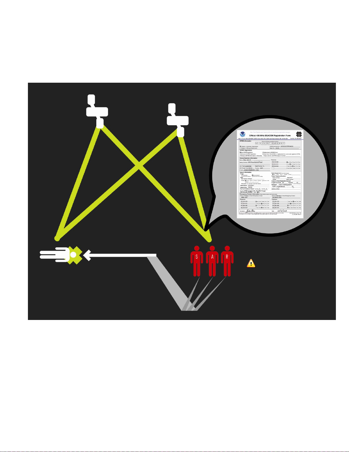
YOUR RESCUE WILL
BE DELAYED IF YOUR
BEACON ISN’T PROPERLY
REGISTERED!
Your personalized ID code programmed inside
each EPIRB is transmitted to Search and Rescue
(SAR).
SAR forces use this code to pull up your
registration to find out valuable information about
who needs help.
SECTION 1 - REGISTRATION OF 406 MHZ MEMORY CAPSULES
1.1 Why is registration important?
As the owner of this 406 MHz beacon, it is mandatory that you register it with the EPIRB national authority of
your country: It is the law.
every two years by the owner.
Please note that all 406 MHz beacons are required to have their registration updated
HOW REGISTRATION WORKS:
All 406 MHz beacons transmit a Unique Identifier Number (UIN) when activated. This UIN is programmed into the
beacon based on the country in which the beacon is registered, thus authorities are able to determine which country’s
database will have your registration information. SAR forces will have information as to who you are as the owner of
the beacon, the name and type of vessel that you have, your homeport, and who to contact that might know of your
current situation - but only if your beacon has been properly registered. Valuable search and rescue resources are
wasted every year responding to false alarms, and registering your beacon helps to resolve false alarms quickly.
Page 5

1.2 What country should I register in?
Register your beacon with the EPIRB national authority of the country for which the beacon was programmed, typically
the country where purchased, regardless of where you do your boating.
The beacon must be reprogrammed if you, as the owner, move or the boat sails under a different country than the one
for which the beacon was previously programmed. To verify the country for which a beacon is programmed, see the
label with the UIN (Unique Identification Number) on the back of the unit. Units that do not have a country specified on
the UIN label are programmed for the United States.
1.3 How do I register?
Registration in the United States
The national authority that accepts registrations in the United States is the National Oceanic and Atmospheric
Administration (NOAA).
Here are three ways to register:
1. The fastest and easiest way to register is online at www.beaconregistration.noaa.gov/.
2. Faxing a registration is also acceptable. Fax the registration form to the fax number on the top of the
registration form.
NOTE: Do not confuse the registration form with the ACR Electronics warranty card.
3. If online or fax registration is not available, mail the registration form with the pre-addressed, postage paid
envelope to:
NOAA SARSAT Capsule Registration
NSOF, E/SP3
4231 Suitland Road
Suitland, MD 20746
All registration forms will be entered in the 406 MHz beacon registration database within 48 hours of receipt. The
information you provide on the registration form is used for rescue purposes only.
A confirmation letter, a copy of the actual registration and a proof-of-registration decal will be mailed to you within two
weeks. When you receive these documents, please check the information carefully, then affix the decal to your
beacon in the area marked ―BEACON DECAL HERE.‖ If you do not receive confirmation back from NOAA in the
expected timeframe, call toll free (888) 212-7283 for assistance.
Registration outside of the United States
In countries other than the United States, 406 MHz beacons are registered with that country’s national authority at the
time of purchase. The sales agent should have assisted you in filling out the forms and sending them to the country’s
national authority. Alternatively, many countries allow online registration in the International 406 MHz Beacon
Registration Database (IBRD) at www.406registration.com.
To verify that the unit is properly programmed for your country, view the UIN label on the back of the unit. In the event
that the beacon is not programmed for your country, the sales agent (if properly equipped) can reprogram the unit for
the correct country.
1.4 Do I need a radio license?
In the United States, you may or may not need to obtain or update a radio station license. Check the FCC’s website at
http://wireless.fcc.gov/services/index.htm?job=licensing&id=ship_stations or call toll-free (888) 225-5322 (CALLFCC)
for the latest information.
Outside of the United States, contact your local authority for the requirements.
Y1-03-0199 Rev. C 2
Page 6

1.5 Change of Ownership or Contact Information
It is the owner’s responsibility to advise the national authority of any change in the information on the registration form.
If the current owner is transferring the memory capsule to a new owner, the current owner is required to inform the
National Authority by letter, fax or telephone, of the name and address of the new owner. The new owner of the
memory capsule is required to provide the National Authority with all of the information requested on the registration
form. This obligation transfers to all subsequent owners. Registration forms are available from NOAA. Call (888) 2127283 or visit our website at www.acrelectronics.com.
1.6 Commercial Vessels Worldwide
406 MHz memory capsules that are carried on commercial vessels worldwide, should be registered with the country
where the vessel is flagged regardless of where the vessel operates. When a commercial vessel acquires a 406 MHz
memory capsule from outside of its home country, the memory capsule should be reprogrammed for the home country
and registered there.
1.7 Lost or Stolen Memory Capsules
Inform NOAA immediately at 1-888-212-SAVE (7283), or your national authority, that your memory capsule has been
lost. They will update your memory capsule registration with the appropriate information.
Things that you need to do:
• Report to your local authorities that the memory capsule has been lost or stolen.
• Contact NOAA at 1-888-212-SAVE (7283), or your national authority, with the following information so
your EPIRB registration information can be updated with the appropriate remarks:
- Police Department Name
- Police Phone Number
- Police Case Number
If your memory capsule were to activate, the information you provide will be forwarded to the appropriate search and
rescue authorities who will ensure that your memory capsule gets back to you.
If someone attempts to register a memory capsule reported as lost or stolen, NOAA or your national authority will notify
the appropriate police department.
Visit the Cospas-Sarsat website for more detailed information: www.cospas-sarsat.org
SECTION 2 – PRODUCT FEATURES
2.1 Memory Storage System
The float-free memory capsule contains non-volatile memory (FLASH), intended to store ship parameters in real time.
The storage memory will continually store the last 12 hours (minimum) of received data. The interface between the SVDR (Simplified Voyage Data Recorder) and the memory capsule is a standard 10/100 Base-T Ethernet connection
using TCP/IP standard protocol.
Power for the capsule is provided over the same Ethernet cable using PoE (Power Over Ethernet). This feature has
the advantage in that a separate power cable is not required.
Much like a black box on an airplane, in an emergency your float free 406 memory capsule will store the last twelve
hours of the ship’s critical and navigational data to be retrieved and reviewed to assist in explaining the cause of the
accident.
If the ship should sink, the hydrostatic release unit will sense the water pressure and release the memory capsule out
of the bracket and into the water. This happens when the hydrostatic release essentially releases the spring located
behind the memory capsule. This spring will trigger the flex data cable cutting mechanism to activate and slice the flex
data cable disconnecting the memory capsule from the bracket while the spring also pushes the memory capsule into
the open water. Once in the water the memory capsule will be activated by built in water sensor and upon reaching the
water surface will begin transmitting a 406 MHz signal to the Cospas-Sarsat satellite system. The built in GPS receiver
will search to acquire the latitude and longitude positions and upon acquiring this data will include this information into
the distress message. The memory capsule will continue to operate for a minimum of 7 days.
Y1-03-0199 Rev. C 3
Page 7
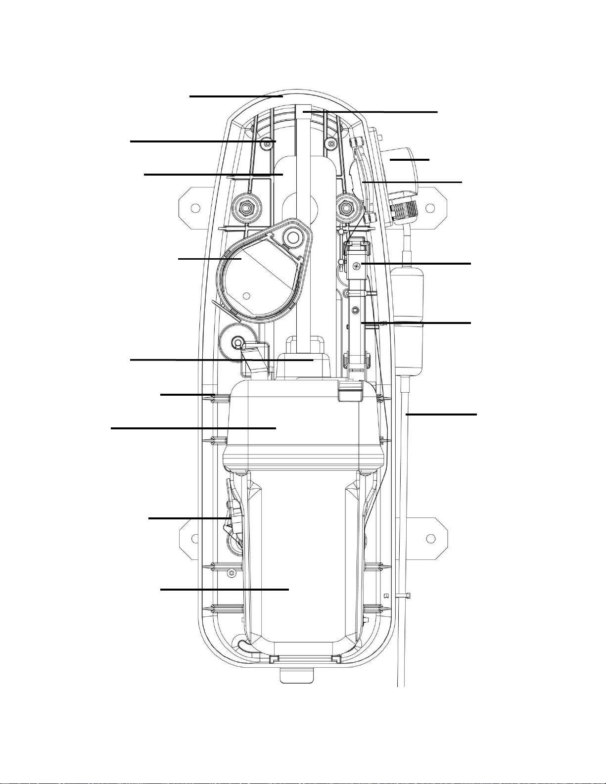
Hydrostatic Release Unit
Data Transfer Cable
Cutter Mechanism
(Activation Trigger)
Memory Capsule Antenna
Warning Plate
(not shown)
Cat 5 Cable
(Located behind
bracket shield)
Strobe Light
Battery Compartment
Data Transfer into
Memory Capsule
Memory Capsule
Ejector Spring
Data Transfer Junction Box
Cutter Mechanism
(Cable Slot)
Float Free Memory Capsule Components
Front view
Figure 1
Water Sensor
Deactivation Magnet
SeaShelter2™ Bracket
Electronic
Housing
Y1-03-0199 Rev. C 4
Page 8
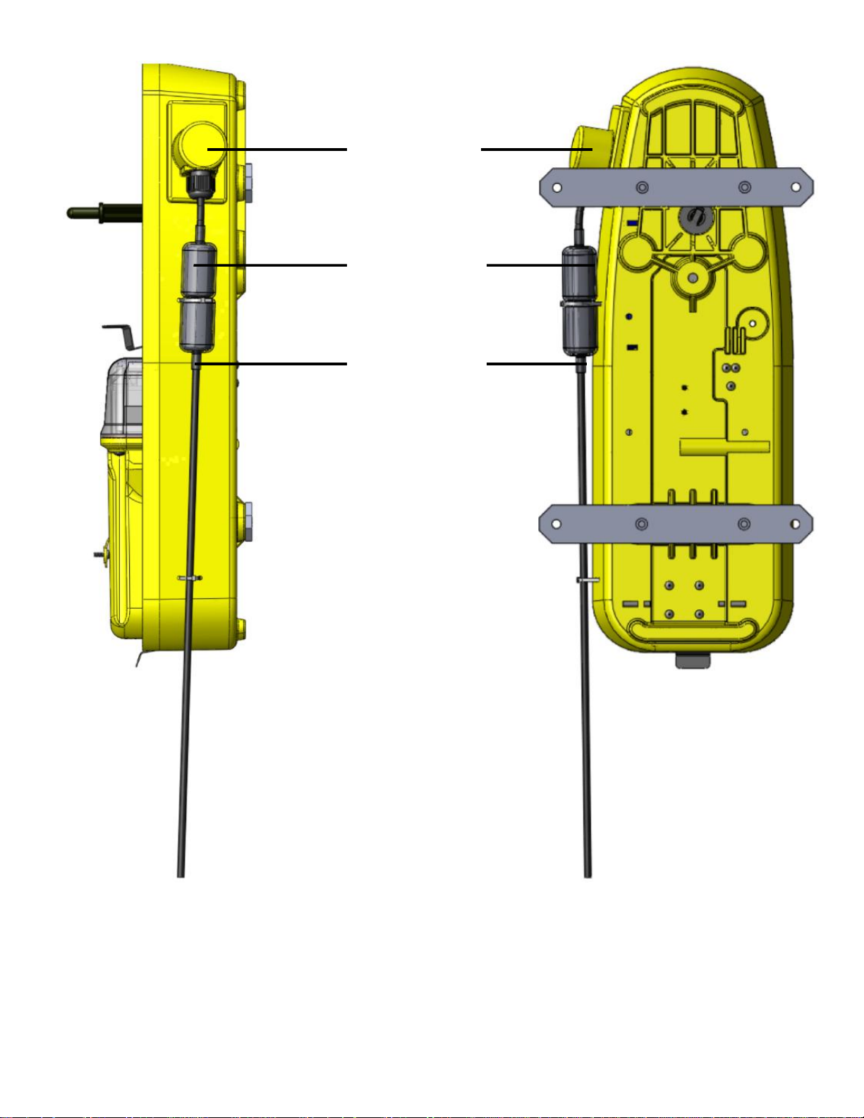
Side and Back view of Float
Free Memory Capsule
Figure 2
Data Transfer
Junction Box
RJ-45 Waterproof
Connection
PoE Cat 5
Ethernet cable
from S-VDR
Main Unit
Y1-03-0199 Rev. C 5
Page 9

SECTION 3 - FALSE ALARMS
3.1 Prevention of False Alarms
Your memory capsule can be activated by two different methods.
1. When the memory capsule is out of its bracket and in the water, the unit is transmitting.
2. When the switch is moved to the ON position, in or out of the bracket, the unit is transmitting.
There are a few precautions that should be taken to prevent false alarms.
Do not transport memory capsule within 1 meter (3.3ft) of a magnetic source.
Do not mount memory capsule within 1 meter (3.3ft) of a magnetic source.
Do not store memory capsule outside of its bracket if it can get wet.
Do not clean memory capsule with a water hose and brush.
Do not mount memory capsule backwards in bracket.
3.2 Reporting of False Alarms
Should there be, for any reason, an inadvertent activation or false alarm, it must be reported to the nearest SAR
(search and rescue) authorities. The information that should be reported includes the memory capsule Unique
Identifier Number (UIN), Date, Time, duration and cause of activation, as well as location of memory capsule at the
time of activation.
To Report False Alarms in the United States Contact any of the Following:
Atlantic Ocean / Gulf of Mexico
USCG Atlantic Area Command Center
Tel: (757) 398-6390
Pacific Ocean Area
Tel: (510) 437-3700
From Any Location
USCG HQ Command Center
Tel (800) 323-7233
To Report False Alarms Worldwide Contact your National Authority.
SECTION 4 - INSTALLATION / ASSEMBLY
4.1 Mounting Location
The location selected must be sufficiently rigid to support the weight (approximately 9 lbs) of the total installation and at
the same time consider vibration, exposure to the elements, exposure to surrounding hazards, such as equipment
movement, doors being opened, accidental covering, personnel traffic, etc. The memory capsule must be located
no further than 50 meters (164 ft) from the S-VDR main unit.
Also to be considered in selecting a location for installation is the harmful effect that certain corrosive vapors might
have on the memory capsule. Under no circumstances should a location be selected for installation where the memory
capsule would be jeopardized by any foreign articles that emit corrosive vapors being temporarily or permanently
positioned during ―at sea‖ or ―in port‖ activities.
Location aboard a vessel must be chosen to allow the memory capsule to float free of sinking craft and as high as
possible especially on smaller vessels. This will help ensure operation of the hydrostatic release unit in the event the
vessel capsizes without sinking.
Do not mount the memory capsule in the vicinity (3.3 ft.) of strong magnetic (such as loud speakers) or electrical (such
as radar or high power radio transmitter) fields. The memory capsule should not be mounted closer than (3.3 ft) to a
navigation compass.
Y1-03-0199 Rev. C 6
Page 10

Note: The Sea Shelter has two mounting brackets
for attachment to a flat surface (see Figure 3)
Mounting hole locations
Figure 3
The memory capsule should be mounted securely to a vertical
or horizontal flat surface where there are no overhead
obstructions.
The use of #10 stainless steel hardware is recommended.
There is no need to open the Sea Shelter or remove the SVDR during mounting.
Y1-03-0199 Rev. C 7
Page 11
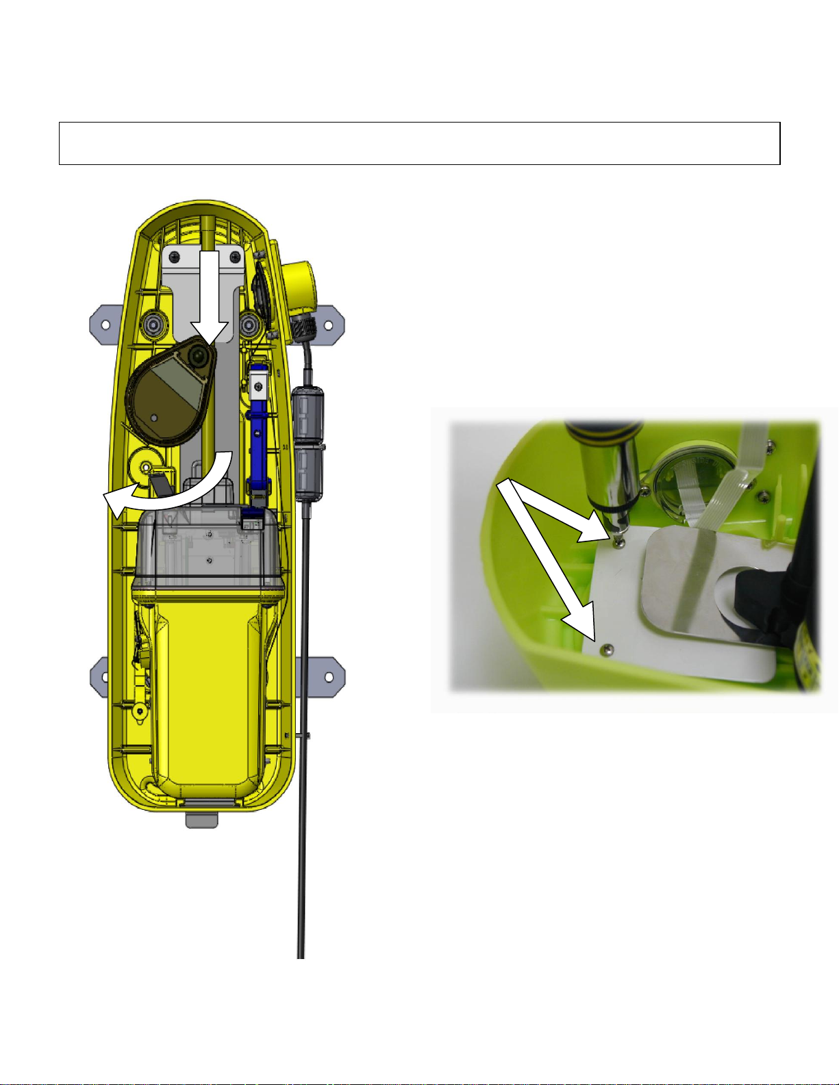
4.2 Assembling your Float Free Memory Capsule
A) Push the release spring back against the bracket
aligning the holes on the spring with the holes in the
back of the bracket. Take the HRU and place the washer
end of the HRU through the larger top whole and slide
down into the smaller slot.
Turn the HRU to the left side of the bracket. This will
lock the HRU and spring into place. Carefully release
the HRU and make sure it is securely in place.
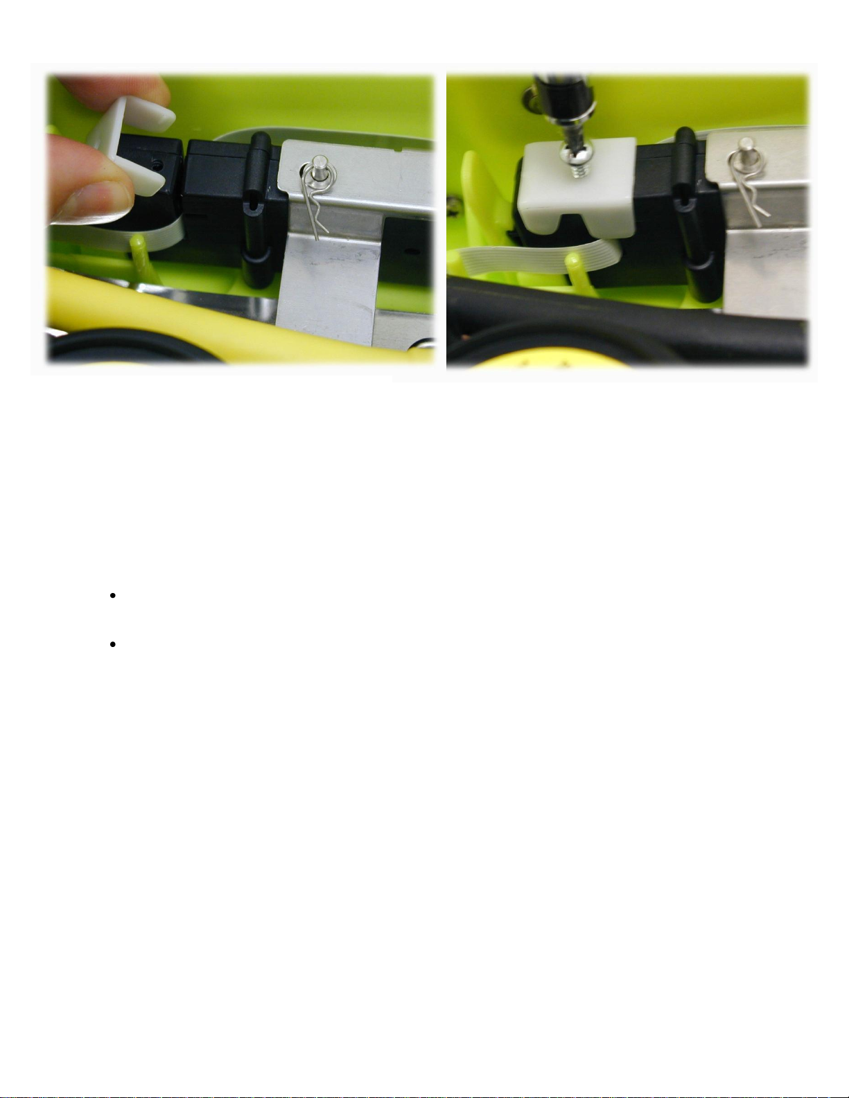
B) Insert the metal warning plate behind the spring so
that the bottom of the plate butts up against the HRU.
With the screws provided, secure the warning plate in
place as shown.
HRU Installation
Figure 4
Warning Plate Installation
Figure 5
NOTE: HRU and cutter assembly replacement can be performed more easily by removing the Sea Shelter from the
bulkhead first. This can be done by removing the screws holding the mounting brackets to the bulkhead.
(To remove all components, reverse these directions at step 5).
1. HRU and warning plate installation
Y1-03-0199 Rev. C 8
Page 12

2. Cutter Mechanism Installation
Release Arm
Flex Cable Slot
Release Pin
Release Arm
Flex Cable Slot
Cutter Mechanism Installation (Figure 6)
A) Insert the flex cable cutter mechanism into place.
B) Position the cutter with the release arm extending across the ejector spring and the slot for the flex cable
positioned at the top.
C) Simply push the cutter into the slot until the teeth connect and lock the mechanism into place. Try to pull it back out
to make sure the device is locked in securely.
Use extreme caution when installing the Float Free Memory Capsule cutter mechanism. By releasing the pin located
on the top of the mechanism, the cutter blade will be activated. Once this device has been activated it must be
replaced by a new cutter mechanism (P/N 2520).
To remove the flex cable cutter mechanism from the bracket first remove the flex cable from the cutter (if already
installed). Next, simultaneously push the two plastic bracket teeth in opposite directions. While the two teeth are
pushed back pull the cutting mechanism out of the bracket.
Y1-03-0199 Rev. C 9
Page 13

3. ZIF Connection and Data Transfer Cable Installation
Step 1 Step 2 Step 3
ZIF Connection Install
Figure 7
TOP
BOTTOM
Data is stored in the memory capsule using the data transfer cable which connects to the junction box on the
bracket, runs thru the cutter mechanism and attaches to the left side of the memory capsule. This cable is
connected to both the junction box and the memory capsule using ZIF (Zero Insertion Force) connectors.
NOTE: ZIF connectors are fragile. To avoid breaking the connectors, touch them carefully. Do not
apply too much pressure to the movable part of the connector when opening or closing it.
To connect the data transfer cable to a ZIF connector, follow these steps:
1. Using your thumb and index finder, pull down on the movable part of the ZIF connector open.
2. Orient the end of the cable with the ZIF connector, and insert the blank side (or printed side) of the cable into
the connector.
3. While holding the cable firmly in place, close the ZIF connector. To ensure a firm connection, make sure the
ZIF connector is completely closed.
To disconnect the data transfer cable from a ZIF connector, follow these steps:
1. Using your thumb and index finder, pull down on the movable part of the ZIF connector open.
2. Pull up gently on the movable part of the connector until the cable is released.
3. Grasp the cable and pull it out of the connector.
4. Data Transfer Cable Window Installation
After the flex data cable is connected to bracket and memory capsule, the protective window must be installed.
The protective window caps come with pre-lubricated O-ring assembled on the window cap ensures a tight,
waterproof fit.
Y1-03-0199 Rev. C 10
Page 14

Align the side window cap holes with the memory capsule or bracket and using a phillips head screwdriver,
Window Cap
Installation
Figure 8
Data Transfer Cable Alignment
Figure 9
fasten the window cap in place with the provided screws.
4.2.5 Data Transfer Cable Alignment
The data transfer cable connects the memory capsule to the
bracket which in turn connects to the PoE and S-VDR. The
flex data cable comes with two flex connectors on either end
accompanied by protective window caps.
To remove the memory capsule from the bracket you must
unscrew the window cap and unplug the flex connector from
the memory capsule.
To remove the flex cable from the cutter mechanism you
must remove the top screw from the cutter slot door and
open the door. Then simply slide the cable out of the slot.
Y1-03-0199 Rev. C 11
Page 15
Data Transfer Cable in Cutter
Figure 10
The installation step is placing the data transfer cable inside the cutter mechanism. Remove the top screw from the
flex cable slot and open the white door (see Figure 10). Slide the data transfer cable along the side of the cutter
mechanism and into the slot as shown above. Close the flex cable slot door and secure shut with by replacing the top
screw.
Final Installation Steps:
Now the memory capsule is armed and ready for service.
Place the protective top cover on the memory capsule, placing the bottom clamp through the top cover
opening on the bottom and the secure the top closed by placing the cotter pin thru the hydrostatic release
rod.
Connect the Cat. 5 cable to your S-VDR unit and ensure that the S-VDR unit is communicating properly
with your float free 406 memory capsule. Consult your technical user’s guide for proper installation to your
S-VDR.
4.3 Visual Inspection
Visually inspect the area surrounding the installation site for hidden hazards, obstacles, etc., that may have been
overlooked during selection. If there is any doubt as to the ready accessibility to the memory capsule at all times or if
any condition may appear to be questionable, make a complete and thorough investigation before making final
approval of the installation.
4.4 Important Expiration Dates
The label on the hydrostatic release mechanism inside of the bracket and the replacement date label on the outside of
the bracket MUST be marked with the date of expiration at time of installation according to coastal marine authority
regulations.
To record the expiration date on the hydrostatic release mechanism, with a permanent indelible marker mark off the
dates to indicate the month and year two years from date of installation. Write the date of expiration with an indelible
marker on the label appearing on the outside cover.
Y1-03-0199 Rev. C 12
Page 16

Expiration Date Labels
Figure 11
Cutter Mechanism
HRU
Memory Capsule
SECTION 5 - OPERATION
5.1 General
The memory capsule is designed to be automatically deployed and activated. The memory capsule is designed to
operate best while floating in water. Hand held operation should be avoided when possible. Do not operate inside a life
raft or under any similar cover or canopy.
Changes in the laws governing memory capsules have mandated that the memory capsule be armed at all times. If
certain criteria are met, the memory capsule will begin transmitting.
The memory capsule is equipped with sensors to detect when it is no longer in its bracket (a deployment condition)
and other sensors to determine if it is in water.
Two conditions must be satisfied for the memory capsule to automatically activate:
1) It must be out of its bracket,
2) It must be in the water,
Note: Either condition by itself will not automatically activate the memory capsule.
The memory capsule is designed to allow the user to perform periodic testing while the memory capsule is in the
release bracket to assure a functioning memory capsule.
5.2 Automatic Deployment and Activation
Automatic deployment and activation occurs when the vessel sinks and a hydrostatic release device frees the memory
capsule from the bracket allowing it to float to the surface. Built-in sensors detect that the memory capsule is no longer
in its bracket and is in water. This condition will automatically activate the memory capsule.
Note: Transmissions of the 121.5 MHz and 406 MHz signal will not occur until 100 seconds after activation.
Y1-03-0199 Rev. C 13
Page 17

5.3 Manual Deployment and Activation
Memory Capsule Instruction Label
Figure 12
The memory capsule can be manually activated by lifting the thumb switch to a vertical position, sliding it towards the
antenna and pushing back down to the opposite side of the memory capsule. Activating the memory capsule in this
manner breaks off the ―Activation Indicator Plastic Pin‖ and allows the switch to properly seat, show the ―I‖ symbol
(ON).
5.4 Deactivation
The memory capsule can be deactivated by:
If manually activated:
1) Returning the thumb switch to the ―OFF‖ position.
If automatically activated:
1) Removing the memory capsule from the water. The memory capsule normally takes up to 12 seconds to
deactivate, or
2) Placing the memory capsule back into the release bracket.
If the memory capsule continues to operate after it has been deactivated, remove the four screws holding the unit
together and unplug the battery to disable the unit. Return it to a service center for repair.
5.5 Full Functional Self Test
Please read all instructions before performing any of the tests. Be prepared to record data from the test.
Self-test is initiated by momentarily lifting the thumb switch to a vertical position and holding it in this position for at
least two seconds and at most 4 seconds. A beep and the simultaneous lighting of the red LED indicate the initiation of
the test. The buzzer will beep an additional four times as the red LED lights simultaneously. The green LED will then
light, followed by a flash of the strobe, indicating a successful test. During self-test, an actual satellite message is
transmitted while certain key performance parameters are measured and recorded. The self-test message is modified
to prevent the satellite from forwarding an alert message during self-test.
Y1-03-0199 Rev. C 14
Page 18

The memory capsule can be tested in or out of the release bracket.
The sequence of tests is:
1. Check Data Integrity ........................................ Beep and lights up red LED if passed
............................................................................. Stop if failed
2. Check 406 MHz Synthesizer ........................... Beep and lights up red LED if passed
............................................................................. Stop if failed
3. Check RF Power/Battery ................................. Beep and lights up red LED if passed
............................................................................. Stop if failed
4. Check internal GPS ......................................... Beep and lights up red LED if passed
............................................................................. Stop if failed
5. Turn on green LED to indicate Successful Test.
6. Flash Strobe Light to test Strobe.
If all of the above occurs, the test has been successful.
NOTE: The homing memory capsule at 121.5 MHz is inhibited during self test.
It is strongly recommended to perform the full functional self test on the memory capsule on a monthly basis.
If the thumb switch is accidentally or inadvertently put in the vertical or test position (not in the OFF or ON position), the
memory capsule would still be turned ON and would drain the battery. The chance of this happening accidentally or
inadvertently is very unlikely. However, if this should occur, the memory capsule will sound a beep once per second
and will alternately flash the red and green LED’s at a rate of one per second until the memory capsule is turned OFF.
It is important that the memory capsule be turned OFF immediately (lowering the thumb switch to the OFF position,
thumb switch at rest in the front position) if this alert is ever obtained.
5.6 Internal GPS Test
Warning: The following test should never be performed more than once during the five-year life of the battery
pack! Return the unit if this test needs to be repeated (see Page 1 for return information).
The memory capsule is fitted with an internal Global Positioning System (GPS) receiver that will determine the
navigational coordinates, latitude and longitude, of its position on the globe to be transmitted to the emergency system.
When the memory capsule is turned ON, the GPS is immediately turned ON and it immediately begins acquiring data.
Initially the red Light Emitting Diode (LED), flashes once per second to indicate the memory capsule is turned ON and
operating. As soon as the GPS receiver acquires good navigational data the red LED stops blinking and the green
LED flashes once per second to indicate that the internal GPS receiver has acquired good navigational data. Once
good navigational data has been obtained the GPS receiver waits for 20 minutes before looking for new navigational
data again. If for any reason a time period of 4 hours passes without the GPS receiver being able to update the last
good set of navigational data, the message transmitted by the memory capsule will revert back to default data. At this
point the green LED will stop blinking and the red LED will flash once per second. If at any time after this, good
navigational data is obtained, this data will be transmitted, the red LED will stop blinking and the green LED will flash
once per second.
Performing the Internal GPS test
To perform the internal GPS test, make sure that you perform the test outside with a clear view of the sky. This will
help the GPS locate a satellite and reduce the amount of time the GPS engine remains on, saving valuable battery life.
If the thumb switch is held in the vertical position after the full functional self-test has finished, the buzzer will beep and
the red LED will light simultaneously. This beep and simultaneous red LED indicates that the GPS has been turned ON
and a live test of the internal GPS has begun. At this point the thumb switch should be allowed to return to its normal
OFF position. The GPS will remain ON until good navigation data has been obtained or until 10 minutes has elapsed.
If good navigation data has been obtained, the GPS will be turned OFF and the green LED will light for at least 3
seconds and the strobe will flash once. This navigation data is not saved for use when the memory capsule is turned
ON. A green LED and strobe flash indication is proof that the GPS is functioning properly and that the memory capsule
is in a location or environment where it can receive the necessary signals from satellites. If the GPS does not acquire
good navigation data, the GPS will turn OFF after 10 minutes and there will be no successful green LED indication.
This test should never be performed more than once during the five-year life of the battery pack to prevent excessive
current drain! The memory capsule must remain under observation to witness the results of the test.
Y1-03-0199 Rev. C 15
Page 19

SECTION 6 - CARE AND MAINTENANCE
At least every ninety days, the mounting bracket and float free memory capsule should be inspected for deterioration
and/or buildup that may affect the function of the memory capsule or automatic release.
Also carefully inspect the memory capsule case for any visible cracks. Cracks may admit moisture, which could falsely
activate the memory capsule or otherwise cause a malfunction. Any cracking observed should be immediately returned
for repairs (See returning product information on page 1).
Clean the memory capsule and the mounting bracket to remove residue buildups. It is recommended that the mounting
bracket be wiped with a damp cloth.
The hydrostatic release unit (HRU) must be replaced by the date indicated on the float free mounting bracket. The
hydrostatic release can be replaced by removing the memory capsule from the bracket, then sliding the hydrostatic
release assembly out of the keyed opening on the spring and mounting bracket. Insert the new hydrostatic release
assembly, in place by engaging it to the opening of the ejection spring and case. When servicing the HRU, it is
required that you replace the entire hydrostatic assembly, including hydrostatic release, release rod and all hardware
(P/N 9490 Universal kit). Failure to replace the entire assembly can cause the bracket to malfunction. Always use
original ACR replacement parts. Use of unauthorized replacement parts will void your warranty and may cause the
bracket to malfunction. Place memory capsule into the mounting bracket, and replace cover, securing in place with
hitch pin going through the hydrostatic release rod.
Check antenna for tightness.
The battery (P/N 1078) must be replaced by the date indicated on the memory capsule. At each inspection, check the
time remaining until replacement is required. Battery should be replaced if the memory capsule has been activated for
any use other than the self test.
NOTE: There are no user serviceable items inside the memory capsule. DO NOT OPEN THE MEMORY
CAPSULE EXCEPT TO DISABLE IN CASE OF FAULTY ACTIVATION.
Self contained long life batteries with a five-year recommended replacement cycle provide power. See factory
authorized service center for replacement.
Battery replacement includes servicing the memory capsule by replacing the lithium batteries, o-rings, testing the water
seal and the electrical properties.
Always refer all long life battery replacement and other memory capsule service to a factory authorized service center.
For battery replacement information, please refer to Section 10.
The memory capsule contains lithium batteries which meet the requirements of the DOT Hazardous Materials
Regulations. They also meet the United Nations Classification of Lithium Batteries for Shipment as "Non – Dangerous
Goods".
Data transfer cable cutting mechanism
Like the HRU, the data transfer cable and cutting mechanism (ACR P/N 2518) should be replaced every two years.
Y1-03-0199 Rev. C 16
Page 20

SECTION 7 - THE SEARCH AND RESCUE SYSTEM
7.1 General Overview
Memory capsule's provides distress alerting via radio transmission on 406 MHz to satellites of the Cospas-Sarsat
network. ACR's Float Free 406 Memory Capsule can also transmit a distress alert to the GEOSAR network that
includes GPS latitude and longitude coordinates that are inputted through an I/R Interface that connects to the data
output of a GPS Receiver.
The message transmitted is unique for each beacon, which provides identification of the transmitter through computer
access of registration files maintained by the National Oceanic and Atmospheric Administration or other National
Authority. Remember, if your beacon is not registered, Search and Rescue (SAR) Authorities do not know who you
are, or how to contact anyone who might know anything about your situation (Refer to section 1).
Once the signal (406 MHz) is relayed through the LEOSAR and/or GEOSAR network, SAR forces determine who is
closest, and then track the signal using the 121.5 MHz homing frequency for intermediate and short-range location.
7.2 Satellite Detection
Memory capsule's transmits to the satellite portion of the Cospas-Sarsat System. Cospas-Sarsat is an international
system that uses Russian Federation and United States low altitude, near-polar orbiting satellites (LEOSAR) that
assist in detecting and locating activated 121.5/243 MHz beacons and 406 MHz Satellite beacons.
COSPAS and SARSAT satellites receive distress signals from memory capsule transmitting on the frequency of 406
MHz. The Cospas-Sarsat 406 MHz beacon signal consists of a transmission of non-modulated carriers followed by a
digital message format that provides identification data. The 406 MHz system uses Satellite-borne equipment to
measure and store the Doppler-shifted frequency along with the beacons digital data message and time of
measurement. This information is transmitted in real time to an earth station called the Local User Terminal (LUT),
which may be within the view of the satellite, as well as being stored for later transmission to other LUTs.
The LUT processes the Doppler-shifted signal from the LEOSAR and determines the location of the beacon; then the
LUT relays the position of the distress to a Mission Control Center (MCC) where the distress alert and location
information is immediately forwarded to an appropriate Rescue Coordination Center (RCC). The RCC dispatches
Search and Rescue (SAR) forces.
The addition of the GEOSAR Satellite system greatly improves the reaction time for a SAR event. This satellite system
has no Doppler capabilities at 406 MHz, but will relay the distress alert to any of the LUT stations. When there is GPS
data included in the distress message, SAR authorities instantly know your location to within 110 yards. This speeds
up the reaction time by not having to wait for one of the LEOSAR satellite to pass overhead. Because most of the
search and rescue forces presently are not equipped to home in on the 406 MHz Satellite beacons signal, homing
must be accomplished at 121.5 MHz.
7.3 Global Positioning System (GPS)
The GPS system is a satellite group that enables a GPS receiver to determine its exact position to within 30m
anywhere on Earth. With a minimum of 24 GPS satellites orbiting the Earth at an altitude of approximately 11,000
miles they provide users with accurate information on position, velocity, and time anywhere in the world and in all
weather conditions. The memory capsule stores this data into its distress transmission allowing search and rescue
forces to narrow the search into a very small area and thus minimize the resources required and dramatically
increases the effectiveness of the overall operation.
Y1-03-0199 Rev. C 17
Page 21

Figure 13- Satellite coverage
Figure 15- GPS satellite orbits
Figure 14- GEOSAR satellite orbits
Y1-03-0199 Rev. C 18
Page 22

SECTION 8 - AUTHORIZATIONS
Prod. No.
Model No.
Cat. I
Memory
2515.4
RLB-35MC X 4 GB Flash Memory
2515.8
RLB-35MC X 8 GB Flash Memory
406 MHz Transmitter
Frequency
406 MHz
Frequency Stability
±2 parts per billion/100ms
Output Power
5 watts
Digital Message Format
Serialized1
Duration
520 ms
Rate
400 bps
Encoding
Biphase L
Modulation
±1.1 radians peak
1
Leaves ACR with Serialized U.S. code but can be reprogrammed at a service center to Maritime or other
coded format including nationality of registration.
121.5 MHz Transmitter
Frequency
121.5 MHz
Frequency Tolerance
±50 ppm
Output Power
25 mW PEP
Modulation
Type
AM (3K20A3X)
Sweep Range
400 to 1200 Hz
Sweep Rate
3 Hz
Duty Cycle
37.5%
8.1 Approvals
The memory capsule meets the requirements of Federal Communications Commission (FCC) Part 80; and GMDSS.
Applicable Documents:
RTCM Standard for 406 MHz Satellite EPIRBs
Cospas-Sarsat Document C/S T.001 Oct. 04, C/S T.007, Oct. 04
FCC Part 80.1101(C) (s): EPIRB
Part 80, subpart W: GMDSS
For complete type approval information, please refer to our website at www.acrelectronics.com.
8.2 Characteristics
The memory capsule is a floatable, battery operated unit. The memory capsule case, with its external antenna, is
waterproof. The semiconductor circuits are mounted within the case assembly that also contains the battery power
supply. A ―Test/On‖ switch is installed on top of the memory capsule, along with a strobe light. The memory capsule
must be stored in its special mount, free of obstructions aboard a vessel for automatic float-off. The unit is self-buoyant
and no external flotation devices are required.
8.3 Technical Data - memory capsule
The memory capsule is available in two combinations. The following product codes define the options available to
meet specific operational requirements:
8.4 Specifications
Y1-03-0199 Rev. C 19
Page 23

Antenna
Frequency
406 & 121.500 MHz
Polarization
Vertical
VSWR
Less than 1.5/1
GPS Antenna
12 Channel Parallel Receiver
Xenon Strobe
Light Color
White
Output Power
0.75 effective candela
Flash Rate
20—30 per minute
General/Environmental
Battery Life
Operating
48 hours minimum
Replacement Interval
5 years or after use in an emergency
Operating Temperature Range
CLASS 1 -40°C to +55°C
Storage Temperature Range
CLASS 1 -50°C TO +70°C
Size (EPIRB less Antenna)
7.0 x 4.25 x 3.62 in. (17.8 x 10.8 x 9.2 cm)
Antenna Height
7.5" (19.05 cm)
EPIRB Material
High impact and UV resistant plastic
Color
ACR-treuse™ (High-Vis Yellow)
Weight (complete assembly)
Approximately 9 lbs
Waterproof
Exceeds RTCM Standards - Factory Tested to 10
meters at room temperature
8.5 Accessories
Mounting Case
Construction ACR-treuse™ high visibility yellow, high Impact and UV resistant HDPE
Size 6.5" x 17.1" (16.51 cm x 43.4 cm)
Release System Hydrostatic with manual override
Hydrostatic Release Kits
ACR P/N 9490
Hydro and data cable cutter kit
ACR P/N 2517
Complete Flex data cable/cutter assembly
ACR P/N 2518
Replacement Data Transfer Cable (only Cable)
ACR P/N 2519
Replacement Data Transfer Cable Cutting Mechanism (only flex cable cutting mechanism)
ACR P/N 2520
Battery Replacement Kit
ACR P/N 1078 (ACR Battery Replacement Service Center only)
Y1-03-0199 Rev. C 20
Page 24

SECTION 9- WARRANTY
9.1 Limited Warranty
This product is warranted against factory defects in material and workmanship for a period of 1 (one) year* from date
of purchase or receipt as a gift. During the warranty period ACR Electronics, Inc. will repair or, at its option, replace the
unit at no cost to you for labor, materials and return transportation from ACR. For further assistance, please contact
our Technical Service Department at ACR Electronics, Inc., 5757 Ravenswood Road, Fort Lauderdale, FL 33312-
6645. Email: service@acrelectronics.com, Fax: +1 (954) 983-5087, Telephone: +1 (954) 981- 3333.
This warranty does not apply if the product has been damaged by accident or misuse, or as a result of service or
modification performed by an unauthorized factory. Except as otherwise expressly stated in the previous paragraph,
THE COMPANY MAKES NO REPRESENTATION OR WARRANTY OF ANY KIND, EXPRESS OR IMPLIED, AS TO
MERCHANTABILITY, FITNESS FOR A PARTICULAR PURPOSE, OR ANY OTHER MATTER WITH RESPECT TO
THIS PRODUCT. The Company shall not be liable for consequential or special damages.
To place the warranty in effect, register online at www.acrelectronics.com or return the attached card within 10 days.
*Five years for the following products: EPIRB, PLB, S-VDR, SSAS.
9.2 Useful Life Policy
The typical service life of a properly maintained Product is limited to 12 years from date of manufacture. Products that
are 12 years and 1 month or older from date of manufacture will not be serviced by ACR or our Battery Replacement
Centers. A Product that is 12 or less years old from date of manufacture will be serviced as long as the unit appears fit
to be placed back into its final operational cycle. Service includes the replacement of those items that must be
replaced at service intervals and the verification that the device appears to be in good mechanical and electrical
working condition by an ACR authorized service technician.
9.3 Notices
ACR Electronics diligently works to provide a high quality Product Support Manual, however, despite best efforts,
information is subject to change without notice, and omissions and inaccuracies are possible. ACR cannot accept
liability for manual contents. To ensure that you have the most recent version of the Product Support Manual, please
visit the ACR website at www.acrelectronics.com.
©2008 by ACR Electronics, Inc., part of Cobham plc. All rights reserved. Reproduction in whole or in part is permitted
only with permission of ACR Electronics, Inc. Ongoing product improvements may change product specifications
without notice.
Trademarks or registered trademarks are the property of their respective owners.
Y1-03-0199 Rev. C 21
Page 25

EC DECLARATION OF CONFORMITY
0735
yy
ACR Electronics, Inc. hereby declares that the following product is in conformity with Council Directive
96/98/EC of 20 December 1996 on Marine Equipment (MED) as amended by Commission Directive
2002/75/EC of 2 September 2002, and has been type examined as described in this Declaration. In
accordance with the Directive, the product will be marked with the MED Mark of Conformity as follows:
yy = Last two digits of the year in which the mark is affixed
Product: 406 MHz (COSPAS_SARSAT) Emergency Position-Indicating Radio Beacon (EPIRB) with
Simplified Voyage Data Recorder (S-VDR) Float-Free Memory Capsule
MED Item A.1/5.6
Trade Name: Float Free 406 Memory Capsule
Model: RLB-35MC
Notified Body: Bundesamt fϋr Seeschifffahrt und Hydrographie (BSH)
Notified Body No. 0735
Bernhard-Nocht-Str. 78
20359 Hamburg, Germany
EC Type Examination (Module B) Certificate No. BSH/4612/5060372/06
EC Quality System (Module D) Certificate No. BSH/4613/05101/0555/07
Regulations and IMO Resolution A.694(17) ETSI EN 300 066 V1.3.1 (2001-01)
Standards: IMO Resolution A.810(19) IEC 60945 (2002-08)
IMO Resolution MSC.56(66) IEC 61097-2 (2002-09)
IMO Resolution MSC.120(74) IEC 61996-2 (2006-03)
IMO MSC/Circ.862
Manufacturer: ACR Electronics Inc. European ACR Electronics Inc.
5757 Ravenswood Road Representative: (European Office)
Fort Lauderdale, FL 33312 1 Rose Cottages, Pitmore Lane,
USA Sway, Lymington, Hampshire SO41
6BX UK
Signed on behalf of ACR Electronics Inc.
Signed: ___________________________________________
Name: Kerry Greer Date: November 6, 2008
Title: VP Engineering
Document RLB-35MC-001 This Declaration complies with
ISO/IEC 17050-1:2004
ACR Electronics, Inc. is registered by UL to ISO 9001:2000
Y1-03-0199 Rev. C 22
Page 26

INTERNATIONAL MARITIME ORGANIZATION
SHORE BASED MAINTENANCE
The Maritime Safety Committee approved guidelines for shore-based maintenance (SBM) of
satellite EPIRBs, for the purpose of establishing standardized procedures and minimum levels of
service for the testing and maintenance of satellite EPIRBs to ensure maximum reliability whilst
minimizing the risk of false distress alerts. (IMO MSC/Circ.1039)
Products: 406 MHz (COSPAS-SARSAT) Emergency Position-Indicating Radio Beacons (EPIRBs):
ACR Satellite 406™ RLB-27/28 (Cat. I & Cat. II)
ACR Satellite2 406™ RLB-32 (Cat. I & Cat. II)
ACR RapidFix™ RLB-33 (Cat. I & Cat. II)
ACR GlobalFix™ RLB-35 (Cat. I & Cat. II)
ACR GlobalFix™ iPRO RLB-36 (Cat. I & Cat. II)
ACR Float Free 406 Memory Capsule RLB-35MC (Cat. I)
Maintenance 406 MHz satellite EPIRBs should be inspected and tested annually in accordance with
Service Interval: MSC/Circ.1040. Shore-based maintenance of all satellite EPIRBs should be carried out at
intervals not exceeding 5 years. It is recommended that maintenance be performed at the time
when the battery is to be changed.
All ACR 406 MHz EPIRBs shall have their first shore-based maintenance performed on the
same dates as their battery replacement.
SBM Providers: ACR only authorizes battery replacements and shore based maintenance to be performed by
certified ACR service providers.
Manufacturer: ACR Electronics Inc. European ACR Electronics Inc.
5757 Ravenswood Road Representative: (European Office)
Fort Lauderdale, FL 33312 1 Rose Cottages, Pitmore Lane,
USA Sway, Lymington, Hampshire SO41
6BX UK
Signed on behalf of ACR Electronics Inc.
Signed: ____________________________________________________
Name: Kerry Greer Date: September 23, 2008
Title: VP Engineering
ACR Electronics, Inc. is registered by UL to ISO 9001:2000
Y1-03-0199 Rev. C 23
 Loading...