

Page 1

DGL-1 (Dongle)
Programming
Adapter
Description, Operation, Installation and Maintenance Manual
This manual includes data for the equipment that follows:
Component Part No. Model No.
Emergency Locator Transmitter 453-6603 DGL-1
ACR ELECTRONICS, INC / ARTEX
5757 Ravenswood Rd, Ft. Lauderdale, FL
25-69-01
PRODUCTS
33312
JUN
18560
27/12
Cage Code:
Page1of44
570-4010 Rev. D
Initial Issue JUN 30/2005
Page 2

ARTEX PRODUCTS / ACR ELECTRONICS, INC
DESCRIPTION, OPERATION, INSTALLATION AND MAINTENANCE MANUAL
DGL-1, DONGLE (453-4010)
PROPRIETARY INFORMATION
This document contains proprietary information and such information may not be disclosed to others for any
purpose, nor used for manufacturing purposes without written permission from ACR Electronics.
Information in this manual is subject to change without notice. ACR Electronics makes no warranty, expressed
or implied, with regard to this manual, including but not limited to any implied warranties of merchantability,
fitness for a particular purpose, and non-infringement. In addition, ACR Electronics makes no warranty with
regard to the documentation or data contained herein. ACR Electronics is not liable in the event of incidentals,
special, consequential, or any other damages in connection with or arising from furnishing, performance, or
use of this manual.
Reproduction of this publication or any portion thereof by any means is prohibited. for further information contact Sales, ACR Electronics, 5757 Ravenswood Rd, Fort Lauderdale, FL 33312. Telephone (954) 981-3333
AIRWORTHINESS LIMITATIONS
The Airworthiness limitations section is FAA approved and specifies inspections and other maintenance
required under 14 CFR§ 43.16 and 91.403, unless an alternative program has been approved.
IMPORTANT NOTICE
ACR Electronics will be responsible for full distribution and revisions of ICA’s (Instructions for Continued
Airworthiness) For inquiries regarding the content and currency of this manual, contact ACR Electronics,
5757 Ravenswood Rd, Fort Lauderdale, FL 33312. Telephone (954) 981-3333
25-69-01
Page 2 of 44
JUN 27/12
Page 3
ARTEX PRODUCTS / ACR ELECTRONICS, INC
DESCRIPTION, OPERATION, INSTALLATION AND MAINTENANCE MANUAL
DGL-1, DONGLE (453-4010)
RECORD OF REVISIONS
REVISION CHANGE DATE REVISION CHANGE DATE
- RELEASE Nov 06/2002
- DCN 2124 Dec 18/2002
- DCN 2147 Feb 17/2003
- DCN 2188 Apr 21/2003
- DCN 2369 Apr 21/2004
A DCN 3144 Dec 11/2007
B DCA W9612 MMM DD/YYYY
C ECO 14756 Jul 28/2011
D ECO 15119 Jun 27/2012
25-69-01
Page 3 of 44
JUN 27/12
Page 4

ARTEX PRODUCTS / ACR ELECTRONICS, INC
DESCRIPTION, OPERATION, INSTALLATION AND MAINTENANCE MANUAL
DGL-1, DONGLE (453-4010)
THIS IS A BLANK PAGE
25-69-01
Page 4 of 44
JUN 27/12
Page 5
ARTEX PRODUCTS / ACR ELECTRONICS, INC
DESCRIPTION, OPERATION, INSTALLATION AND MAINTENANCE MANUAL
DGL-1, DONGLE (453-4010)
SERVICE BULLETIN LIST
SERVICE
BULLETIN NO
ISSUE
DATE
SUBJECT
MANUAL
REV NO
MANUAL
REV DATE
25-69-01
Page 5 of 44
JUN 27/12
Page 6

ARTEX PRODUCTS / ACR ELECTRONICS, INC
DESCRIPTION, OPERATION, INSTALLATION AND MAINTENANCE MANUAL
DGL-1, DONGLE (453-4010)
THIS IS A BLANK PAGE
25-69-01
Page 6 of 44
JUN 27/12
Page 7

ARTEX PRODUCTS / ACR ELECTRONICS, INC
DESCRIPTION, OPERATION, INSTALLATION AND MAINTENANCE MANUAL
DGL-1, DONGLE (453-4010)
LIST OF EFFECTIVE PAGES
SUBJECT PAGE DATE SUBJECT PAGE DATE
Title Page 1 Jun 27/12 Installation (cont.) 30 Jun 27/12
Notices 2 Jun 27/12 31 Jun 27/12
Record of Revisions 3 Jun 27/12 32 Jun 27/12
4 BLANK 33 Jun 27/12
Service Bulletin List 5 Jun 27/12 34 BLANK
6 BLANK 35 Jun 27/12
List of Effective Pages 7 Jun 27/12 36 Jun 27/12
8 BLANK 37 Jun 27/12
Table of Contents 9 Jun 27/12 38 Jun 27/12
10 Jun 27/12 Illustrated Parts List 39 Jun 27/12
List of Figures 11 Jun 27/12 40 Jun 27/12
12 BLANK 41 Jun 27/12
Introduction 13 Jun 27/12 42 Jun 27/12
14 BLANK 43 Jun 27/12
15 Jun 27/12 44 Jun 27/12
16 Jun 27/12
17 Jun 27/12
18 BLANK
Description and Operation 19 Jun 27/12
20 Jun 27/12
21 Jun 27/12
22 Jun 27/12
Test and Fault Isolation 23 Jun 27/12
24 Jun 27/12
25 Jun 27/12
26 Jun 27/12
Removal 27 Jun 27/12
28 Jun 27/12
Installation 29 Jun 27/12
25-69-01
Page 7 of 44
JUN 27/12
Page 8

ARTEX PRODUCTS / ACR ELECTRONICS, INC
DESCRIPTION, OPERATION, INSTALLATION AND MAINTENANCE MANUAL
DGL-1, DONGLE (453-4010)
THIS IS A BLANK PAGE
25-69-01
Page 8 of 44
JUN 27/12
Page 9

ARTEX PRODUCTS / ACR ELECTRONICS, INC
DESCRIPTION, OPERATION, INSTALLATION AND MAINTENANCE MANUAL
DGL-1, DONGLE (453-4010)
TABLE OF CONTENTS
RECORD OF REVISIONS . . . . . . . . . . . . . . . . . . . . . . . . . . . . . . . . . . . . . . . . . . . . . . . . . . . . . . . . . . . . 3
SERVICE BULLETIN LIST . . . . . . . . . . . . . . . . . . . . . . . . . . . . . . . . . . . . . . . . . . . . . . . . . . . . . . . . . . . 3
LIST OF EFFECTIVE PAGES . . . . . . . . . . . . . . . . . . . . . . . . . . . . . . . . . . . . . . . . . . . . . . . . . . . . . . . . . 5
TABLE OF CONTENTS . . . . . . . . . . . . . . . . . . . . . . . . . . . . . . . . . . . . . . . . . . . . . . . . . . . . . . . . . . . . . 9
LIST OF FIGURES . . . . . . . . . . . . . . . . . . . . . . . . . . . . . . . . . . . . . . . . . . . . . . . . . . . . . . . . . . . . . . . 11
INTRODUCTION
1. Manual Usage . . . . . . . . . . . . . . . . . . . . . . . . . . . . . . . . . . . . . . . . . . . . . . . . . . . . . . . . . . . 13
A. General . . . . . . . . . . . . . . . . . . . . . . . . . . . . . . . . . . . . . . . . . . . . . . . . . . . . . . . . . . . . . 13
B. Application . . . . . . . . . . . . . . . . . . . . . . . . . . . . . . . . . . . . . . . . . . . . . . . . . . . . . . . . . . . 13
2. Model Descriptions . . . . . . . . . . . . . . . . . . . . . . . . . . . . . . . . . . . . . . . . . . . . . . . . . . . . . . . . 14
A. Dongle DGL-1 Programming Adapter . . . . . . . . . . . . . . . . . . . . . . . . . . . . . . . . . . . . . . . . 14
3. Approvals . . . . . . . . . . . . . . . . . . . . . . . . . . . . . . . . . . . . . . . . . . . . . . . . . . . . . . . . . . . . . . 14
A. Dongle DGL-1 . . . . . . . . . . . . . . . . . . . . . . . . . . . . . . . . . . . . . . . . . . . . . . . . . . . . . . . . 14
4. List of Acronyms, Abbreviations, and Definitions . . . . . . . . . . . . . . . . . . . . . . . . . . . . . . . . . . . 15
5. References . . . . . . . . . . . . . . . . . . . . . . . . . . . . . . . . . . . . . . . . . . . . . . . . . . . . . . . . . . . . . . 17
A. Regulatory Documents . . . . . . . . . . . . . . . . . . . . . . . . . . . . . . . . . . . . . . . . . . . . . . . . . . 17
B. Other Documents . . . . . . . . . . . . . . . . . . . . . . . . . . . . . . . . . . . . . . . . . . . . . . . . . . . . . . 17
DESCRIPTION AND OPERATION . . . . . . . . . . . . . . . . . . . . . . . . . . . . . . . . . . . . . . . . . . . . . . . . . . . . . 19
1. Description . . . . . . . . . . . . . . . . . . . . . . . . . . . . . . . . . . . . . . . . . . . . . . . . . . . . . . . . . . . . . 19
A. Functional Overview . . . . . . . . . . . . . . . . . . . . . . . . . . . . . . . . . . . . . . . . . . . . . . . . . . . . 19
B. Components . . . . . . . . . . . . . . . . . . . . . . . . . . . . . . . . . . . . . . . . . . . . . . . . . . . . . . . . . . 19
C. 24-Bit Address Reprogramming Functionality . . . . . . . . . . . . . . . . . . . . . . . . . . . . . . . . . . . 20
2. Operation . . . . . . . . . . . . . . . . . . . . . . . . . . . . . . . . . . . . . . . . . . . . . . . . . . . . . . . . . . . . . . 21
A. Operational Overview . . . . . . . . . . . . . . . . . . . . . . . . . . . . . . . . . . . . . . . . . . . . . . . . . . . 21
3. Specifications . . . . . . . . . . . . . . . . . . . . . . . . . . . . . . . . . . . . . . . . . . . . . . . . . . . . . . . . . . . . 22
A. Electrical . . . . . . . . . . . . . . . . . . . . . . . . . . . . . . . . . . . . . . . . . . . . . . . . . . . . . . . . . . . . 22
Table 1. Electrical Specifications . . . . . . . . . . . . . . . . . . . . . . . . . . . . . . . . . . . . . . . . . . . 22
B. Physical . . . . . . . . . . . . . . . . . . . . . . . . . . . . . . . . . . . . . . . . . . . . . . . . . . . . . . . . . . . . . 22
Table 2. Physical Specifications . . . . . . . . . . . . . . . . . . . . . . . . . . . . . . . . . . . . . . . . . . . 22
TEST AND FAULT ISOLATION
1. General . . . . . . . . . . . . . . . . . . . . . . . . . . . . . . . . . . . . . . . . . . . . . . . . . . . . . . . . . . . . . . . . 23
A. Applicability . . . . . . . . . . . . . . . . . . . . . . . . . . . . . . . . . . . . . . . . . . . . . . . . . . . . . . . . . . 23
B. Regulatory Requirements . . . . . . . . . . . . . . . . . . . . . . . . . . . . . . . . . . . . . . . . . . . . . . . . 23
2. Inspection . . . . . . . . . . . . . . . . . . . . . . . . . . . . . . . . . . . . . . . . . . . . . . . . . . . . . . . . . . . . . . 23
A. Periodic Inspection . . . . . . . . . . . . . . . . . . . . . . . . . . . . . . . . . . . . . . . . . . . . . . . . . . . . . 23
25-69-01
Page 9 of 44
JUN 27/12
Page 10

ARTEX PRODUCTS / ACR ELECTRONICS, INC
DESCRIPTION, OPERATION, INSTALLATION AND MAINTENANCE MANUAL
DGL-1, DONGLE (453-4010)
3. Test Procedures . . . . . . . . . . . . . . . . . . . . . . . . . . . . . . . . . . . . . . . . . . . . . . . . . . . . . . . . . . 24
A. General . . . . . . . . . . . . . . . . . . . . . . . . . . . . . . . . . . . . . . . . . . . . . . . . . . . . . . . . . . . . . 24
B. 24-Bit Address Reprogramming Verification Test . . . . . . . . . . . . . . . . . . . . . . . . . . . . . . . . 24
C. 15-Digit Hex ID Verification . . . . . . . . . . . . . . . . . . . . . . . . . . . . . . . . . . . . . . . . . . . . . . . 25
4. Fault Isolation . . . . . . . . . . . . . . . . . . . . . . . . . . . . . . . . . . . . . . . . . . . . . . . . . . . . . . . . . . . 26
A. Troubleshooting Guidelines . . . . . . . . . . . . . . . . . . . . . . . . . . . . . . . . . . . . . . . . . . . . . . . 26
Table 3. Troubleshooting Guide . . . . . . . . . . . . . . . . . . . . . . . . . . . . . . . . . . . . . . . . . . . . . . . 26
REMOVAL
1. DGL-1 Programming Adapter . . . . . . . . . . . . . . . . . . . . . . . . . . . . . . . . . . . . . . . . . . . . . . . . . 27
A. Dongle Removal . . . . . . . . . . . . . . . . . . . . . . . . . . . . . . . . . . . . . . . . . . . . . . . . . . . . . . . 27
2. Material or Equipment Return . . . . . . . . . . . . . . . . . . . . . . . . . . . . . . . . . . . . . . . . . . . . . . . . 28
A. Shipment Information . . . . . . . . . . . . . . . . . . . . . . . . . . . . . . . . . . . . . . . . . . . . . . . . . . . 28
B. Return Material Authorization . . . . . . . . . . . . . . . . . . . . . . . . . . . . . . . . . . . . . . . . . . . . . 28
INSTALLATION
1. Regulatory Requirements and Guidelines . . . . . . . . . . . . . . . . . . . . . . . . . . . . . . . . . . . . . . . . 29
A. Applicability . . . . . . . . . . . . . . . . . . . . . . . . . . . . . . . . . . . . . . . . . . . . . . . . . . . . . . . . . . 29
B. TSO C126, Paragraph D . . . . . . . . . . . . . . . . . . . . . . . . . . . . . . . . . . . . . . . . . . . . . . . . . 29
C. FAA . . . . . . . . . . . . . . . . . . . . . . . . . . . . . . . . . . . . . . . . . . . . . . . . . . . . . . . . . . . . . . . . 29
D. Canada . . . . . . . . . . . . . . . . . . . . . . . . . . . . . . . . . . . . . . . . . . . . . . . . . . . . . . . . . . . . . 29
E. Other Countries . . . . . . . . . . . . . . . . . . . . . . . . . . . . . . . . . . . . . . . . . . . . . . . . . . . . . . . 29
F. RTCA . . . . . . . . . . . . . . . . . . . . . . . . . . . . . . . . . . . . . . . . . . . . . . . . . . . . . . . . . . . . . . 30
2. Mechanical . . . . . . . . . . . . . . . . . . . . . . . . . . . . . . . . . . . . . . . . . . . . . . . . . . . . . . . . . . . . . 31
A. Dongle Location . . . . . . . . . . . . . . . . . . . . . . . . . . . . . . . . . . . . . . . . . . . . . . . . . . . . . . . 31
B. Dongle Installation . . . . . . . . . . . . . . . . . . . . . . . . . . . . . . . . . . . . . . . . . . . . . . . . . . . . . 31
3. Wiring . . . . . . . . . . . . . . . . . . . . . . . . . . . . . . . . . . . . . . . . . . . . . . . . . . . . . . . . . . . . . . . . . 32
A. General Considerations and Recommendations . . . . . . . . . . . . . . . . . . . . . . . . . . . . . . . . . 32
B. Dongle Wiring . . . . . . . . . . . . . . . . . . . . . . . . . . . . . . . . . . . . . . . . . . . . . . . . . . . . . . . . 33
C. 24-Bit Address Reprogramming . . . . . . . . . . . . . . . . . . . . . . . . . . . . . . . . . . . . . . . . . . . . 37
ILLUSTRATED PARTS LIST
1. Introduction . . . . . . . . . . . . . . . . . . . . . . . . . . . . . . . . . . . . . . . . . . . . . . . . . . . . . . . . . . . . 39
A. Purpose . . . . . . . . . . . . . . . . . . . . . . . . . . . . . . . . . . . . . . . . . . . . . . . . . . . . . . . . . . . . . 39
B. IPL Usage Guide . . . . . . . . . . . . . . . . . . . . . . . . . . . . . . . . . . . . . . . . . . . . . . . . . . . . . . 39
2. Manufacturer Name and Address . . . . . . . . . . . . . . . . . . . . . . . . . . . . . . . . . . . . . . . . . . . . . . 40
A. Ordering Information . . . . . . . . . . . . . . . . . . . . . . . . . . . . . . . . . . . . . . . . . . . . . . . . . . . 40
3. Explanation of Detailed Parts List Entries . . . . . . . . . . . . . . . . . . . . . . . . . . . . . . . . . . . . . . . . 41
A. Fig # & Item Column . . . . . . . . . . . . . . . . . . . . . . . . . . . . . . . . . . . . . . . . . . . . . . . . . . . 41
B. Part # Column . . . . . . . . . . . . . . . . . . . . . . . . . . . . . . . . . . . . . . . . . . . . . . . . . . . . . . . . 41
C. Nomenclature Column . . . . . . . . . . . . . . . . . . . . . . . . . . . . . . . . . . . . . . . . . . . . . . . . . . 41
D. UPA (Units Per Assembly) Column . . . . . . . . . . . . . . . . . . . . . . . . . . . . . . . . . . . . . . . . . . 42
4. Detailed Parts List . . . . . . . . . . . . . . . . . . . . . . . . . . . . . . . . . . . . . . . . . . . . . . . . . . . . . . . . 43
25-69-01
Page 10 of 44
JUN 27/12
Page 11

ARTEX PRODUCTS / ACR ELECTRONICS, INC
DESCRIPTION, OPERATION, INSTALLATION AND MAINTENANCE MANUAL
DGL-1, DONGLE (453-4010)
LIST OF FIGURES
Figure 1. DGL-1 (Dongle) Programming Adapter with ELT Cover . . . . . . . . . . . . . . . . . . . . . . . . . . . . 14
Figure 2. DGL-1 (Dongle) Programming Adapter Assembly . . . . . . . . . . . . . . . . . . . . . . . . . . . . . . . . 19
Figure 3. Dongle Removal Sequence . . . . . . . . . . . . . . . . . . . . . . . . . . . . . . . . . . . . . . . . . . . . . . . 27
Figure 4. Dongle Outline and Dimensions . . . . . . . . . . . . . . . . . . . . . . . . . . . . . . . . . . . . . . . . . . . . 31
Figure 5. Dongle Wiring Harness Arrangement . . . . . . . . . . . . . . . . . . . . . . . . . . . . . . . . . . . . . . . . 33
Figure 6. Molex 12-Pin Connector Harness Arrangement . . . . . . . . . . . . . . . . . . . . . . . . . . . . . . . . . 34
Figure 7. Molex Power and Ground Wires . . . . . . . . . . . . . . . . . . . . . . . . . . . . . . . . . . . . . . . . . . . . 35
Figure 8. Dongle Wiring Diagram . . . . . . . . . . . . . . . . . . . . . . . . . . . . . . . . . . . . . . . . . . . . . . . . . . 36
Figure 9. Octal/Hexadecimal to Binary Conversion . . . . . . . . . . . . . . . . . . . . . . . . . . . . . . . . . . . . . . 37
Figure 10. 24-Bit Address Switch Block . . . . . . . . . . . . . . . . . . . . . . . . . . . . . . . . . . . . . . . . . . . . . . . 38
Illustrated Parts List
Figure 11. DGL-1 (Dongle) Programming Adapter Assembly . . . . . . . . . . . . . . . . . . . . . . . . . . . . . . . . 43
Figure 12. Wire Harness . . . . . . . . . . . . . . . . . . . . . . . . . . . . . . . . . . . . . . . . . . . . . . . . . . . . . . . . . 44
25-69-01
Page 11 of 44
JUN 27/12
Page 12

ARTEX PRODUCTS / ACR ELECTRONICS, INC
DESCRIPTION, OPERATION, INSTALLATION AND MAINTENANCE MANUAL
DGL-1, DONGLE (453-4010)
25-69-01
Page 12 of 44
JUN 27/12
Page 13

ARTEX PRODUCTS / ACR ELECTRONICS, INC
DESCRIPTION, OPERATION, INSTALLATION AND MAINTENANCE MANUAL
TASK 25-62-30-870-801
1. Manual Usage
SUBTASK 25-62-30-990-001
A. General
(1) This manual describes the operation, installation, and maintenance of the DGL-1 (Dongle)
Programming Adapter. This information is provided to ensure initial and continued
airworthiness. Information presented in this manual is accurate at time of printing, but is
subject to change. Refer to the Artex products web site at www.acrartex.com for the latest
information and any updates to this manual.
(2) Web links provided in this manual were accurate at time of printing, but may be subject to
change.
DGL-1, DONGLE (453-4010)
INTRODUCTION
(3) Regulatory references contained herein are generally confined to United States and Canadian
requirements and, in any case, should not be considered all encompassing. Consult your
national aviation authority for applicable requirements.
SUBTASK 25-62-30-990-002
B. Application
(1) This manual constitutes supporting data/documentation for the Dongle, including:
(a) Description and Operation
(b) Test and Fault Isolation (includes inspection criteria)
(c) Removal
(d) Installation
(e) Registration
(f) Illustrated Parts List
(2) In the United States, a 406 MHz ELT must be installed and maintained in accordance with the
requirements herein and 14 CFR, FAR Parts 43, and 91; and other airworthiness requirements,
as applicable.
(3) 406 MHz ELT installation and maintenance in all other countries must comply with the
requirements herein and applicable national airworthiness requirements.
(4) The accessories (i.e., remote switch) addressed in this manual are the accessories most
commonly associated with a 406 MHz ELT. Other options, such as a different remote switch
25-69-01
Page 13 of 44
JUN 27/12
Page 14
ARTEX PRODUCTS / ACR ELECTRONICS, INC
DESCRIPTION, OPERATION, INSTALLATION AND MAINTENANCE MANUAL
DGL-1, DONGLE (453-4010)
configuration or a navigation interface, should be installed and maintained in accordance with
the written instructions specific to the accessory.
NOTE
: Contact ACR Electronics, Inc., for optional accessories approved for use with a
ME406 Series ELT.
(5) To ensure proper operation, only parts listed in the Illustrated Parts List of this manual or
those recommended by ACR Electronics, Inc., may be used as replacement parts for the
Dongle.
TASK 25-62-30-990-801
2. Model Descriptions
SUBTASK 25-62-30-990-001
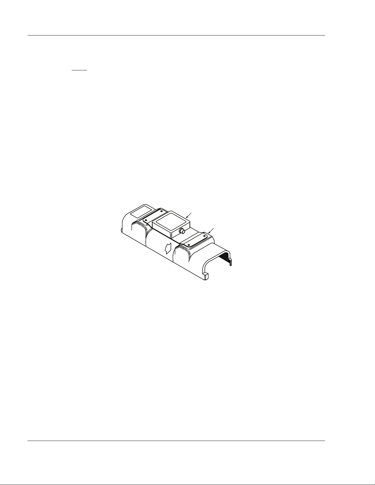
A. Dongle DGL-1 Programming Adapter
(1) The Dongle is a 24-bit address programming adapter with two rows of DIP switches.
(2) The Dongle is an optional auxiliary device attached to an ELT top cover that remains with an
aircraft to allow fleet operators to transfer ELTs between aircraft.
Figure 1. DGL-1 (Dongle) Programming Adapter with ELT Cover
TASK 25-62-30-990-803
3. Approvals
SUBTASK 25-62-30-990-001
A. Dongle DGL-1
(1) FAA TSO-C126 - System Component
(2) ETSO 2C126 - System Component
DGL-1 DONGLE
PROTECTIVE COVER
25-69-01
Page 14 of 44
JUN 27/12
Page 15

ARTEX PRODUCTS / ACR ELECTRONICS, INC
DESCRIPTION, OPERATION, INSTALLATION AND MAINTENANCE MANUAL
DGL-1, DONGLE (453-4010)
TASK 25-62-30-990-805
4. List of Acronyms, Abbreviations, and Definitions
SUBTASK 25-62-30-990-001
Term
AC Advisory Circular – A Federal Aviation Administration (USA) bulletin
CFR Code of Federal Regulations – The general and permanent rules pub-
COSPAS-SARSAT The international search and rescue consortium that governs the
DIP SWITCH A set of manual electric switches packaged in a group in a standard
DRIP LOOP Extra wire length used to form a U-shaped bend in a wire or cable.
ELT Emergency Locator Transmitter – ELTs are installed on aircraft and
Definition
with special information. For the purposes of this document, the acronym AC does not refer to electrical alternating current.
lished in the Federal Register by the executive departments and
agencies of the Federal Government. Title 14, “Aeronautics and
Space” contains the FARs.
international satellite-based search and rescue distress alert detection
and information distribution system. For a complete description go to
the official web site for the International COSPAS-SARSAT Program.
dual in-line package (DIP).
Water or other fluids will flow down to the botton of the lop and drip
off. Electrical connections are made at the top of the loop.
used to send emergency signals to the SAR satellite system. The
word “Beacon” is associated with these devices.
FAA Federal Aviation Administration – The United States government
agency for aircraft safety and regulation.
FAR Federal Aviation Regulations – The rules and regulations governing
the manufacture, certification, operation, maintenance, repair, and
alteration of aircraft in the United States.
FORM 337 FAA Form 337 is required anytime a major repair and/or major altera-
tion is performed on an aircraft. Refer to FAR, Part 43, Appendix A
and the definitions of Major Repair/Alteration contained in FAR, Part 1
for guidance.
ID Identification
MIL The three-letter acronym that stands for “Military” and proceeds mili-
tary specifications and standards numbers (e.g., MIL-W-XXXX would
25-69-01
Page 15 of 44
JUN 27/12
Page 16

ARTEX PRODUCTS / ACR ELECTRONICS, INC
DESCRIPTION, OPERATION, INSTALLATION AND MAINTENANCE MANUAL
DGL-1, DONGLE (453-4010)
indicate a wire specification and MIL-STD-XXXX would indicate a
standard).
MSB Most Significant Bit - The bit position in a binary number having the
greatest value.
P/N Part Number – Refers to an ACR part number, unless otherwise
noted. Part numbers are also indicated with parentheses (e.g., XXXXXXX).
PLUG The term “Plug”, within the context of this document, refers to the
male half of an electrical connector.
RECEPTACLE The term “Plug,” within the context of this document, refers to the
male half of an electrical connector.
RTV A rubbery silicon-based adhesive typically used to prevent vibration
problems and water intrusion.
SAR Search and Rescue
TSO Technical Standard Order – A TSO is a minimum performance stan-
dard issued by the FAA for specified materials, parts, processes, and
appliances used on civil aircraft.
VHF Very High Frequency – The 30 MHz to 300 MHz radio frequency band.
25-69-01
Page 16 of 44
JUN 27/12
Page 17

ARTEX PRODUCTS / ACR ELECTRONICS, INC
DESCRIPTION, OPERATION, INSTALLATION AND MAINTENANCE MANUAL
TASK 25-62-30-990-806
5. References
SUBTASK 25-62-30-990-001
A. Regulatory Documents
(1) The following regulatory documents are referred to herein. When referring to such
documents, it is the manual user’s responsibility to ensure they are using the latest revision or
release of such documents. To that end, the revision designator of specific document numbers
has not been included, with the exception of the RTCA document listing, which reflects the
revision level of the documents at the time of TSO testing and certification.
(2) Except in the case of a printed manual, reference documents available on-line or source
locations are linked to applicable web sites.
(3) United States
(a) AC 43-210, “Standardized Procedures for Requesting Field Approval of Data, Major
Alterations, and Repairs”
DGL-1, DONGLE (453-4010)
(b) AC 43.9-1, “Instructions for Completion of FAA Form 337”
(c) AC 43-13-1, “Acceptable Methods, Techniques, and Practices – Aircraft Inspection and
Repair”
(d) AC 43.13-2, “Acceptable Methods, Techniques, and Practices - Aircraft Alterations”
(4) COSPAS-SARSAT
(a) C/S G.005, “Cospas-Sarsat Guidelines on 406 MHz Beacon Coding, Registration and
Type Approval”
(b) C/S S.007, “Handbook of Beacon Regulations”
SUBTASK 25-62-30-990-002
B. Other Documents
(1) The following documents are available on-line at the Artex products web site at
www.acrartex.com, or from ACR Electronics upon request.
(a) 570-1000, “ELT Test Set (ETS) Operation Manual”
25-69-01
Page 17 of 44
JUN 27/12
Page 18

ARTEX PRODUCTS / ACR ELECTRONICS, INC
DESCRIPTION, OPERATION, INSTALLATION AND MAINTENANCE MANUAL
DGL-1, DONGLE (453-4010)
THIS IS A BLANK PAGE
25-69-01
Page 18 of 44
JUN 27/12
Page 19

ARTEX PRODUCTS / ACR ELECTRONICS, INC
DESCRIPTION, OPERATION, INSTALLATION AND MAINTENANCE MANUAL
TASK 25-62-30-870-801
1. Description
SUBTASK 25-69-01-870-001
A. Functional Overview
(1) The Dongle is connected to an ELT to allow the operator to easily program aircraft 24-bit
address (Standard Location Protocol) into a compatible ELT.
(2) When power is applied, the Dongle verifies the 24-bit address set locally on its DIP switches
matches the 24-bit address stored in the memory of the ELT when power is applied. If the
Dongle address matches the ELT address, the Dongle will shut down. If the ELT address does
not match, the Dongle will program the ELT with its locally set address, and then shut down.
SUBTASK 25-69-01-870-002
DGL-1, DONGLE (453-4010)
DESCRIPTION AND OPERATION
B. Components
(1) The Dongle is designed to mount to a protective top cover on the ELT with four screws. See
"Figure 2. DGL-1 (Dongle) Programming Adapter Assembly".
DONGLE
SCREW
(TYP. OF 8)
GASKET
COVER
COVER ASSEMBLY
Figure 2. DGL-1 (Dongle) Programming Adapter Assembly
(2) The Dongle can be mounted directly to the airframe within the proximity of the ELT to utilize
the prefabricated cable assembly (P/N 611-4010).
Page 19 of 44
25-69-01
JUN 27/12
Page 20

ARTEX PRODUCTS / ACR ELECTRONICS, INC
DESCRIPTION, OPERATION, INSTALLATION AND MAINTENANCE MANUAL
DGL-1, DONGLE (453-4010)
SUBTASK 25-69-01-870-003
C. 24-Bit Address Reprogramming Functionality
CAUTION
(1) The Dongle provides the means to reprogram ELTs with 24-bit address location protocol
(2) This capability facilitates swapping ELTs from one aircraft to another when performing routine
(3) If the ELT is not programmed with a 24-bit address location protocol, the Dongle will not
: THE PROGRAMMING AND LABELING OF THE ELT MUST MATCH THE AIRCRAFT IN
WHICH IT IS INSTALLED. REMARK THE ELT PRODUCT LABEL AS NECESSARY TO
REFLECT NEW PROGRAMMING AND/OR COUNTRY OR REGISTRY. CONTACT THE
LOCAL REGULATORY AUTHORITIES RESPONSIBLE FOR ELT REGISTRATION AND
REFER TO THE APPLICABLE ELT ABBREVIATED COMPONENT MAINTENANCE MANUAL
FOR ELT REGISTRATION REQUIREMENTS.
programming.
maintenance, etc., without losing a significant amount of time reprogramming ELTs.
reprogram the ELT.
25-69-01
Page 20 of 44
JUN 27/12
Page 21

ARTEX PRODUCTS / ACR ELECTRONICS, INC
DESCRIPTION, OPERATION, INSTALLATION AND MAINTENANCE MANUAL
TASK 25-69-01-870-802
2. Operation
SUBTASK 25-69-01-870-001
A. Operational Overview
(1) Operation of the Dongle is automatic and requires no operator interface other than activating
the +28 VDC power source and verifying no failure mode is present. See “Fault Isolation” on
page 26.
(2) The following conditions must be true for the Dongle to function:
(a) +28 VDC aircraft power must be applied to the unit (i.e., the power source must be
switched on).
(b) The Cobham Artex ELT must be programmed with a 24-bit address long message
(Standard Location Protocol).
NOTE
: The Dongle is designed for use only with Cobham Artex ELTs. No other use of
the Dongle is certified or approved by Cobham.
DGL-1, DONGLE (453-4010)
(c) The ELT software version must be V133M, V134B, or V135C (displayed on the ELT
product label).
(3) Once the Dongle verifies or updates the ELT address, it shuts down.
25-69-01
Page 21 of 44
JUN 27/12
Page 22

ARTEX PRODUCTS / ACR ELECTRONICS, INC
DESCRIPTION, OPERATION, INSTALLATION AND MAINTENANCE MANUAL
TASK 25-69-01-870-803
3. Specifications
SUBTASK 25-69-01-870-001
A. Electrical
(1) Table 1 lists the electrical specifications of the Dongle.
CRITERIA PARAMETER CHARACTERISTIC
Pin 1 RX Input TTL
Pin 2 TX Output TTL
Pin 3 5.6 VDC Output 5.6 VDC ±0.3 VDC
DGL-1, DONGLE (453-4010)
Table 1. Electrical Specifications
Pin 4 Power Input +28 VDC ±10 VDC
Pin 5 ELT Ground ELT Pin 11
Pin 6 DGL-1 Ground Aircraft Ground
Cobham ELT
Software Compatibility
SUBTASK 25-69-01-870-002
B. Physical
(1) lists the physical specifications of the Dongle.
CRITERIA PARAMETER CHARACTERISTIC
Weight
V133M, V134B, V135C
Table 2. Physical Specifications
DGL-1 4.8 ox (90 g)
Protective Top Cover 6.7 oz (190 g)
DGL-1 Harness 1 oz (28 g)
Dimensions (L x H x W) Dongle mounted on ELT Top Cover
25-69-01
10.95 x 2.42 x 3.36 in.
(278 x 61 x 85 mm)
Page 22 of 44
JUN 27/12
Page 23

ARTEX PRODUCTS / ACR ELECTRONICS, INC
DESCRIPTION, OPERATION, INSTALLATION AND MAINTENANCE MANUAL
TASK 25-69-01-750-801
1. General
SUBTASK 25-69-01-990-001
A. Applicability
(1) This section only covers inspection, testing, and fault isolation procedures specific to the
Dongle.
(2) Refer to the applicable ELT abbreviated component maintenance manual associated with the
ELT to coordinate the requirements herein with the requirements for inspection, test, and fault
isolation of the ELT system as a whole.
SUBTASK 25-69-01-990-002
DGL-1, DONGLE (453-4010)
TEST AND FAULT ISOLATION
B. Regulatory Requirements
(1) The Dongle is considered an integral part to the ELT system, and as such is subject to the
periodic inspection and testing required by the regulatory authorities governing the
installation, operation, and maintenance of ELT systems.
(2) Refer to the application ELT abbreviated component maintenance manual associated with the
ELT for references to the regulatory requirements.
(3) Inspection and testing of the Dongle must be accomplished in conjunction with and on the
same schedule as the ELT and other system components.
TASK 25-69-01-750-802
2. Inspection
SUBTASK 25-69-01-990-001
A. Periodic Inspection
(1) Remove the Dongle in accordance with “Removal” on page 27.
(2) Perform a visual inspection of the physical integrity of the case, gasket, and DIP switches,
checking for:
(a) Damage to the finish,
(b) Corrosion,
(c) Excessive wear of the mounting holes, and
(d) Cracks in the mounting flanges.
25-69-01
Page 23 of 44
JUN 27/12
Page 24

ARTEX PRODUCTS / ACR ELECTRONICS, INC
DESCRIPTION, OPERATION, INSTALLATION AND MAINTENANCE MANUAL
TASK 25-69-01-750-801
3. Test Procedures
SUBTASK 25-69-01-990-001
A. General
DGL-1, DONGLE (453-4010)
CAUTION
(1) This task consists of two subtask testing requirements:
SUBTASK 25-69-01-750-002
B. 24-Bit Address Reprogramming Verification Test
(1) This is a recommended periodic test.
: ANY ELT RUNNING V133 SOFTWARE (SEE PRODUCT LABEL) MUST BE TESTED IN AN
RF CONTAINER, SCREEN ROOM, OR CONNECTED TO A DUMMY LOAD VIA THE
ANTENNA COAX CONNECTION, BECAUSE THE V133 SOFTWARE TRANSMITS A FIXED
TEST MESSAGE AT ELT RESET, NECESSITATING A “LIVE” BROADCAST TO READ THE
ACTUAL MESSAGE. ANY ELT RUNNING V134 OR V135 SOFTWARE TRANSMITS THE
ACTUAL 406 MHZ MESSAGE AT RESET AND MAY BE TESTED IN SITU.
(a) 24-bit address programming test, which verifies ELT/Dongle 24-bit address
reprogramming functionality by initiating reprogramming and checking for the address
change or an error indication.
(b) 15-digit hex ID determination, which reads the programmed hex ID, country, and
country code broadcast in the 406 MHz message and provides instructions for relabeling
and re-registering the ELT, as applicable.
NOTE
: This test procedure verifies the ELT/Dongle has updated the aircraft 24-bit address
ID in the ELT programming.
(2) The following test procedure incorporates the steps necessary to confirm operation of the
Dongle into the “Installed Transmitter Test” procedure defined in the applicable ELT
abbreivated component maintenance manual.
(3) Remove the Dongle in accordance with “Removal” on page 27.
(4) Change the position of the most significant bit (MSB) DIP switch, refer to "Figure 10. 24-Bit
Address Switch Block", on page 38.
(5) Reconnect the Dongle in accordance with “Installation” on page 29.
(6) Apply power to the ELT/Dongle, while the ELT remains off (i.e, inactive). Reprogramming
takes place within 30 seconds of power up.
(7) Monitor the ELT for the next 2 minutes. Refer to the troubleshooting guidelines of the
applicable ELT abbriviated component maintenance manual.
(a) The LEDs on the ELT and remote switch will begin to flash rapidly if reprogramming was
NOT successful.
(b) If the LEDs remain off after two minutes, the ELT has been reprogrammed.
25-69-01
Page 24 of 44
JUN 27/12
Page 25

ARTEX PRODUCTS / ACR ELECTRONICS, INC
DESCRIPTION, OPERATION, INSTALLATION AND MAINTENANCE MANUAL
(8) Verify the 24-bit address has changed as a result of changing the position of the MSB DIP
switch.
(9) Repeat Steps 3 through 8 to return and verify the original configuration of the Dongle.
SUBTASK 25-69-01-750-001
C. 15-Digit Hex ID Verification
(1) 15-digit hex ID verification should be performed any time a Dongle is installed in an aircraft to
verify the ELT is properly labeled and registered.
(2) Perform the following procedure within the first 5 minutes after the hour (UTC), as required by
AC 43.13-1, Chapter 12, § 12-22, Note 3.
(a) Notify any nearby control tower of your intentions.
(b) Verify the ELT/Dongle is powered up and has at least 30 seconds to initialize.
(c) Set the 453-1000 ELT Test Set (ETS) beacon reader to receive and decode the ELT
digital message. Refer to the ETS operating manual (570-1000) for ETS operating
instructions and additional details.
DGL-1, DONGLE (453-4010)
NOTE
: A beacon reader equivalent to the ETS may be used, provided it is capable of
receiving and decoding the 406 MHz digital message.
(d) Place the ETS within 30 feet of the aircraft 406 MHz antenna.
(e) Activate the ELT by placing the control switch or remote switch in the “ON” position.
(f) Allow the ELT to transmit for approximately 5 seconds.
(g) Deactivate the ELT and read the test message broadcast at “turn-off”.
NOTE
: The ELT LED will flash 5 times to indicate a navigation data failure if a Cobham
Nav Interface Unit is not installed with the ELT. The Dongle does not support
the position data function of the ELT. If the ELT flashes other failure codes,
refer to the applicable ELT manual to troubleshoot the problem.
(3) The 15 digit hex ID (i.e., Beacon ID) displayed by the ETS is compared to the hex ID on the
ELT. If identical, no further action is necessary. If different:
(a) Enter the new hex ID on label P/N 591-0999 and affix it to the ELT over the existing hex
ID on the product label.
(b) If country and country code have changed, enter the new information on label (P/N 591-
0429-01) and affix it to the ELT over the existing information on the product label.
(c) Re-register the ELT. Refer to the applicable ELT abbreviated component maintenance
manual for specific ELT registration information and instructions.
25-69-01
Page 25 of 44
JUN 27/12
Page 26

ARTEX PRODUCTS / ACR ELECTRONICS, INC
DESCRIPTION, OPERATION, INSTALLATION AND MAINTENANCE MANUAL
TASK 25-69-01-810-801
4. Fault Isolation
SUBTASK 25-69-01-810-801
A. Troubleshooting Guidelines
(1) "Table 3. Troubleshooting Guide" provides the Dongle troubleshooting guidelines for
installation and operational issues.
SYMPTOM PROBABLE CAUSE POSSIBLE SOLUTION
DGL-1, DONGLE (453-4010)
Table 3. Troubleshooting Guide
ELT and Remote Switch flash
continuously
Dongly is unable to synchronize
with the ELT
Open or short in wiring
Check the ELT protocol is
programmed with a 24-bit
address protocol
Check continuity between pin 1 of
circular connector and pin 12
Check continuity between pin 2 of
circular connector and pin 9 of the
rectangular connector
Check wiring and connections
continuity and security for short
other pins
25-69-01
Page 26 of 44
JUN 27/12
Page 27

ARTEX PRODUCTS / ACR ELECTRONICS, INC
DESCRIPTION, OPERATION, INSTALLATION AND MAINTENANCE MANUAL
TASK 25-69-01-010-801
1. DGL-1 Programming Adapter
SUBTASK 25-69-01-010-001
A. Dongle Removal
(1) See "Figure 3. Dongle Removal Sequence".
SCREW
(TYP. OF 8)
DGL-1, DONGLE (453-4010)
REMOVAL
DONGLE
GASKET
COVER
COVER ASSEMBLY
Figure 3. Dongle Removal Sequence
(2) Remove black circular connector from the Dongle.
(3) Remove the screws attaching the mounting plate to the top cover assembly.
(4) Remove the screws attaching the Dongle to the mounting plate.
25-69-01
Page 27 of 44
JUN 27/12
Page 28

ARTEX PRODUCTS / ACR ELECTRONICS, INC
DESCRIPTION, OPERATION, INSTALLATION AND MAINTENANCE MANUAL
DGL-1, DONGLE (453-4010)
TASK 25-69-01-500-801
2. Material or Equipment Return
SUBTASK 25-69-01-510-001
A. Shipment Information
(1) If any material or equipment is to be returned to the factory, under warranty or otherwise,
ACR Electronics must be notified prior to shipment with the following information:
• Model and serial number of equipment being returned,
• Date purchased,
• Date placed in service,
• Number of hours in service,
• Nature and cause of failure, and
• Remarks, if any.
SUBTASK 25-69-01-580-001
B. Return Material Authorization
(1) Upon receipt of such notice, ACR Electronics, Inc. will issue a Return Material Authorization
(RMA) number which then authorizes return of the material or equipment to the following
address:
(a) Failure to obtain a RMA number and provide the details listed in SUBTASK 25-69-01-510-
001, on page 28 may cause unnecessary delay and/or rejection of the returned material
or equipment.
(b) All material or equipment returned to the factory must be freight prepaid.
Repair and Overhaul
Artex Products / ACR Electronics, Inc.
5757 Ravenswood Road
Fort Lauderdale, FL 33312 USA
Phone: (954) 981-3333
Fax: (954) 983-5087
(c) Acceptable methods of shipment for international return are Airborne, Burlington Air,
DHL, Emery, Federal Express, UPS International, and World Wide only.
NOTE
: Do not use “International Commercial Airlines”, such carriers may cause a loss
of returned material or equipment.
25-69-01
Page 28 of 44
JUN 27/12
Page 29

ARTEX PRODUCTS / ACR ELECTRONICS, INC
DESCRIPTION, OPERATION, INSTALLATION AND MAINTENANCE MANUAL
DGL-1, DONGLE (453-4010)
INSTALLATION
TASK 25-69-01-450-801
1. Regulatory Requirements and Guidelines
SUBTASK 25-69-01-990-001
A. Applicability
(1) The regulatory requirements and guidelines for ELT installations discussed in the following
subtasks are applicable to installation of the DGL-1 Dongle Programming Adapter and must be
applied to the DGL-1 Dongle Programming Adapter. Where the word “ELT” is used in the
following subtasks, read “DGL-1 Dongle Programming Adapter”.
SUBTASK 25-69-01-990-002
B. TSO C126, Paragraph D
(1) TSO approval of the ELT does not constitute installation approval. All installations are subject
to field approval for a given airframe by either an approved FAA DER or FAA FSDO. For
installations outside the US, contact your local civil aviation regulatory agency for details.
SUBTASK 25-69-01-990-003
C. FAA
(1) This manual constitutes supporting data, as described in AC43.9-1, Paragraph 6.h.(2) and AC
43-210, Chapter 2, Paragraph 201(a)(6), and as such may be used as support for FAA field
approval of the ELT/NAV Interface installation.
(2) In addition to the procedures outlined herein and in accordance with FAR Part 43, the installer
must adhere to the aircraft manufacturer’s instructions and recommendations and the
guidelines provided by FAA Advisory Circular AC 43.13-2 “Acceptable Methods, Techniques,
and Practices - Aircraft Alterations”, specifically Chapters 1 through 3, 11, and 13.
(3) By signing the aircraft logbook, and FAA Form 337, the installer is stating the installation has
been performed in accordance with current FAR requirements and the procedures outlined
herein. The completed Form 337 is provided to the FAA and also becomes a permanent part of
the aircraft maintenance records in accordance with AC43-9, Paragraph 17.
SUBTASK 25-69-01-990-004
D. Canada
(1) All installations must be performed in accordance with Canadian Aviation Regulations (CAR)
Part V, Subparts 37, 51, and 71.
SUBTASK 25-69-01-990-005
E. Other Countries
(1) Installations in aircraft outside of the United States and Canada, must be performed in
accordance with applicable regulatory authority rules and regulations.
25-69-01
Page 29 of 44
JUN 27/12
Page 30

ARTEX PRODUCTS / ACR ELECTRONICS, INC
DESCRIPTION, OPERATION, INSTALLATION AND MAINTENANCE MANUAL
SUBTASK 25-69-01-990-006
F. RTCA
(1) DO-204, § 3.1.8 guidelines for mounting a ELT:
(a) The ELT shall be mounted to primary aircraft load carrying structures, such as trusses,
bulkheads, longerons, spars, or floor beams.
(b) The mounts shall have a maximum static local deflection no greater than 0.1 inches (2.5
mm) when a force of 100 lbs (450 newtons) is applied to the mount in the most flexible
direction. Deflection measurements shall be made with reference to another part of the
aircraft not less than 1 foot (0.3 meters) nor more than 3 feet (1.0 meters) from the
mounting location.
(2) DO-182, § 6.2.2.b recommends that:
(a) To maximize the probability of the ELT transmitting a detectable signal after a crash, all
ELT system components, which must survive a crash intact, e.g., transmitter and
external antenna, should be attached to the airframe in such a manner that the
attachment system can support a 100
100, etc.) applied through the center of gravity of the component (ELT, antenna, etc.) in
the plus and minus directions of the three principal axes of the aircraft.
DGL-1, DONGLE (453-4010)
g
load, (ELT weight x 100, ELT antenna weight x
(b) Post-crash critical components of the ELT system, e.g., transmitter and external
antenna, should be mounted as close to each other as possible.
25-69-01
Page 30 of 44
JUN 27/12
Page 31

ARTEX PRODUCTS / ACR ELECTRONICS, INC
DESCRIPTION, OPERATION, INSTALLATION AND MAINTENANCE MANUAL
TASK 25-69-01-410-802
2. Mechanical
SUBTASK 25-69-01-450-001
A. Dongle Location
DGL-1, DONGLE (453-4010)
CAUTION
: AVOID LOCATION THE DONGLE WHERE IT MAY BE SUBJECTED TO UNPROTECTED
EXPOSURE TO HARSH CHEMICAL FLUIDS, SUCH AS DEICING COMPONDS. THESE
TYPES OF CHECMICALS MAY CAUSE DAMAGE TO FASTENERS AND ELECTRICAL
COMPONENTS, AS WELL AS ELECTRICAL CONNECTOR CORROSION.
(1) Mount the Dongle withing 2 feet (610 mm) of the ELT, such that the interface harness does
not exceed 3 feet (914 mm) including strain relief.
(2) The Dongle chassis and ELT are mounted to the same support structure in most installations.
SUBTASK 25-69-01-410-001
B. Dongle Installation
(1) Coordinate the Dongle installation with the ELT installation whenever possible. If the Dongle is
an add-on to an existing ELT installation, extend/modify the existing ELT support structure to
accommodate the Donge.
(2) See "Figure 4. Dongle Outline and Dimensions".
3.36
(85)
2.93
(74)
0.46
(12)
1.92
(49)
2.42
(61)
453-4010
10.95
7.34
4.51
(115)
(186)
(278)
DGL-1
MOUNTING FRAME
PROTECTIVE COVER
Dimensions in inches (mm)
Figure 4. Dongle Outline and Dimensions
(3) Mount the Dongle on the protective top cover on the ELT with four screws (P/N 201-6324-01)
(4) Test the ELT installation in accordance with“Test and Fault Isolation” on page 23.
Page 31 of 44
25-69-01
JUN 27/12
Page 32

ARTEX PRODUCTS / ACR ELECTRONICS, INC
DESCRIPTION, OPERATION, INSTALLATION AND MAINTENANCE MANUAL
DGL-1, DONGLE (453-4010)
TASK 25-69-01-450-805
3. Wiring
SUBTASK 25-69-01-990-001
A. General Considerations and Recommendations
CAUTION
CAUTION
(1) The following wiring and grounding considerations and recommendations are applicable:
(2) Minimum 24 AWG wire size for 24-bit address reprogramming ground wires.
(3) The Dongle is provided with a preassembled wiring harness (P/N 611-4010).
: IF GROUND OR OTHER CONNECTIONS ARE BROKEN OR OTHERWISE DAMAGED, THE
ELT IS STILL CAPABLE OF AUTOMATIC ACTIVATION; HOWEVER, THE COCKPIT
REMOTE SWITCH MAY BE INCAPABLE OF RESETTING THE ELT AND OPERATION MAY
NOT BE INDICATED ON THE REMOTE SWITCH LED.
: INCORRECT TERMINATION OF THE WIRING IN THE CONNECTORS MAY DAMAGE THE
DONGLE. VERIFY THE WIRING AGAINST THE WIRING DIAGRAM AND PERFORM A
CONTINUITY CHECK TO CONFIRM GOOD CONNECTIONS AND PROPER PIN
LOCATIONS.
(a) Minimum 22 AWG wire size.
(b) Shielding is recommended to help prevent EMI and RF interference.
(c) Use high quality conductor meeting MIL-W-16878, M22759, M27500, or a commercial
equivalent acceptable for use in aircraft applications.
(d) Provide a “Drip Loop” at the Dongle and the ELT receptable to divert moisture from the
connections. See “List of Acronyms, Abbreviations, and Definitions” on page 15.
(e) All grounds must be common to aircraft ground.
(4) If the Dongle is being installed with the ELT, refer to the ELT installation and operation
manual and coordinate the wiring installation.
(5) Refer to applicable ELT abbreviated component maintenance manual for Metal or composite
airframe installations.
25-69-01
Page 32 of 44
JUN 27/12
Page 33

ARTEX PRODUCTS / ACR ELECTRONICS, INC
DESCRIPTION, OPERATION, INSTALLATION AND MAINTENANCE MANUAL
SUBTASK 25-69-01-450-002
B. Dongle Wiring
(1) Refer to "Figure 8. Dongle Wiring Diagram", on page 36.
(2) Refer to the applicable ELT abbriviated component maintenance manual for pin configuation
and additional wiring infromation.
DGL-1, DONGLE (453-4010)
TO ANTENNA
(TYP.)
Figure 5. Dongle Wiring Harness Arrangement
(3) A preassembled wire harness (P/N 611-4010) is provided with the Dongle.
NOTE
: Disassembly of the 12 position rectangular connector is required when installing a
Dongle on an aircraft previously equipped with an ARTEX ELT to integrate the wire
harness. Refer to "Figure 6. Molex 12-Pin Connector Harness Arrangement", on
page 34. Use Molex extraction tool (Molex P/N 11-03-0002), or an equivalent tool for
0.062 in. terminal pins.
TO REMOTE
SWITCH
25-69-01
Page 33 of 44
JUN 27/12
Page 34

ARTEX PRODUCTS / ACR ELECTRONICS, INC
DESCRIPTION, OPERATION, INSTALLATION AND MAINTENANCE MANUAL
DGL-1, DONGLE (453-4010)
3
6
2
9
5
1
Figure 6. Molex 12-Pin Connector Harness Arrangement
(4) Assemble the wire harness with the Dongle wire harness (P/N 611-4010). See "Figure 8.
Dongle Wiring Diagram", on page 36.
NOTE
: Remote switch pin numbers are for an ARTEX standard remote switch (P/N 345-
6196-04).
12
8
11
4
7
10
(5) Terminate wires from the horn and remote switch with the male terminal pins provided (P/N
151-6627).
(a) Strip approximately 0.15 in. (3 mm) of insulation from ELT receptacle end of the wires
from the horn and remote switch.
(b) Dress and tin the bare wire ends to prevent the strands from fraying during terminal
crimping operations.
(c) Install the terminal pins with a Molex crimp tool (Molex Tool P/N 63811-330), or
equivalent.
(6) Insert the terminated wires into the applicable locations in the rectangular 12 position
connector.
(7) Fabricate a power wire of sufficient length to reach from the red, un-terminated wire on the
preassembled wire harness to a suitable aircraft +28VDC, switchable power source. See
"Figure 7. Molex Power and Ground Wires", on page 35.
CAUTION
: DO NOT WIRE DONGLE DIRECTLY TO THE AIRCRAFT BATTERY. THE 28 VOLT
DC POWER SOURCE SHOULD BE PROTECTED WITH A .5A FUSE, OR CIRCUIT
BREAKER, AND ON A SWITCH BUS.
(a) A Raychem solder sleeve splice (Raychem P/N D-1744-01) is provided for this
connection.
NOTE
: Refer to Raychem for specific instructions on the splice use. Alternate splices
may be used if installed in accordance with FAA AC 43.13.1A, Section 445,
Splices in Electrical Wire.
(8) Connect the +28VDC power source to the red wire.
25-69-01
Page 34 of 44
JUN 27/12
Page 35

ARTEX PRODUCTS / ACR ELECTRONICS, INC
DESCRIPTION, OPERATION, INSTALLATION AND MAINTENANCE MANUAL
DGL-1, DONGLE (453-4010)
RED
TO 28 VDC
BLACK
TO GROUND
Figure 7. Molex Power and Ground Wires
(9) Connect the ground to the black, un-terminated wire.
NOTE
: Refer to Raychem for specific instructions on the splice use. Alternate splices may be
used if installed in accordance with FAA AC 43.13.1A, Section 445, Splices in
Electrical Wire.
(a) A Raychem solder sleeve splice (Raychem P/N D-1744-01) is provided for this
connection.
(b) For installations of a ELT/Dongle, splice the black wire to an aircraft ground point near
the ELT. See "Figure 8. Dongle Wiring Diagram".
NOTE
: Pin 11 will not be available for remote switch grounding with the Dongle/ELT
installation. Slice a ground for the remote switch .
(c) For Dongle installations on previously installed ELT, ground the un-terminated ground
wire from the remote switch as described above.
(10) Feed the black circular connector through the rectangular hole in the ELT end cap.
(11) Connect the black circular connector to the plug on the Dongle.
25-69-01
Page 35 of 44
JUN 27/12
Page 36

ARTEX PRODUCTS / ACR ELECTRONICS, INC
DESCRIPTION, OPERATION, INSTALLATION AND MAINTENANCE MANUAL
DGL-1, DONGLE (453-4010)
ELT
5.6 V
GND
HRN +
HRN –
G-SWT LOOP
G-SWT LOOP
LED
RST-1
RST-2
EXT ON
1
2
3
5
TX
RX
5.6 V
GND
HRN +
HRN –
LED
RST-1
RST-2
EXT ON
DONGLE
HORN
REMOTE
SWITCH
12
TX
RX
9
10
11
2
4
5
8
1
3
6
7
28 V
GND
GND
4
0.5 A
6
Figure 8. Dongle Wiring Diagram
25-69-01
Page 36 of 44
JUN 27/12
Page 37

ARTEX PRODUCTS / ACR ELECTRONICS, INC
DESCRIPTION, OPERATION, INSTALLATION AND MAINTENANCE MANUAL
SUBTASK 25-69-01-450-002
C. 24-Bit Address Reprogramming
(1) The 24-bit address is composed of binary “1s” and “0s”, with a “1” electrically grounded to the
airframe and “0” electrically open.
(2) Encoding is accomplished by using a 24-bit address switch block which internally grounds
selected addresses.
(3) Remove the Dongle in accordance with “Dongle Removal” on page 27.
(4) Determine the appropriate binary 24-bit address based on the octal or hexadecimal ID code
assigned to the aircraft. See "Figure 9. Octal/Hexadecimal to Binary Conversion".
Example No. 1: Converting ICAO address 50134057 (octal) to
binary 24-bit address
101000001011100000101111
DGL-1, DONGLE (453-4010)
ICAO Octal Address to 24-Bit Binary
40575013
MSB
ADDRESS 1
Example No. 2: Converting ICAO address A0B82F (hexadecimal) to
binary 24-bit address
ICAO Hex Address to 24-Bit Binary
A0B82F
101000001011100000101111
MSB
ADDRESS 1
OCTAL/BINARY
EQUIVALENTS
Octal Binary
00 0 0
10 0 1
20 1 0
30 1 1
41 0 0
51 0 1
61 1 0
71 1 1
HEXADECIMAL/BINARY
EQUIVALENTS
Hex
Binary
0 0 0 0
0
0 0 0 1
1
0 0 1 0
2
0 0 1 1
3
0 1 0 0
4
0 1 0 1
5
0 1 1 0
6
0 1 1 1
7
Hex Binary
1 0 0 0
8
1 0 0 1
9
1 0 1 0
A
1 0 1 1
B
1 1 0 0
C
1 1 0 1
D
1 1 1 0
E
1 1 1 1
F
LSB
ADDRESS 24
LSB
ADDRESS 24
Figure 9. Octal/Hexadecimal to Binary Conversion
(5) Set the 24-bit address switch block switches as appropriate for the 24-bit address binary code
determined in the previous step. See "Figure 10. 24-Bit Address Switch Block", on page 38.
(6) Install the Dongle in accordance with “Dongle Installation” on page 31.
25-69-01
Page 37 of 44
JUN 27/12
Page 38

ARTEX PRODUCTS / ACR ELECTRONICS, INC
DESCRIPTION, OPERATION, INSTALLATION AND MAINTENANCE MANUAL
DGL-1, DONGLE (453-4010)
1
0
MSB
LSB
Figure 10. 24-Bit Address Switch Block
(7) Test the installation in accordance with “24-Bit Address Reprogramming Verification Test” on
page 24.
25-69-01
Page 38 of 44
JUN 27/12
Page 39

ARTEX PRODUCTS / ACR ELECTRONICS, INC
DESCRIPTION, OPERATION, INSTALLATION AND MAINTENANCE MANUAL
TASK 25-69-01-990-801
1. Introduction
SUBTASK 25-69-01-990-001
A. Purpose
(1) This illustrated parts list (IPL) illustrates and lists the spare parts, with attaching hardware,
applicable to the ME406 Series ELT.
(2) Parts and components not listed herein, are not field replaceable and ELT repairs requiring
parts outside the scope of this manual must be accomplished by the manufacturer.
SUBTASK 25-69-01-990-002
B. IPL Usage Guide
DGL-1, DONGLE (453-4010)
ILLUSTRATED PARTS LIST
(1) If the part number is not known:
(a) Find the part in the IPL Figure illustration.
(b) Note the item number assigned to the part.
(c) Refer to the associated parts list and find the item number in the “Fig # & Item” column.
(2) If the part number is known:
(a) Refer to the parts list and find the part in the “Part #” column.
(b) Note the figure number and item number assigned to the part.
(c) Refer to the illustration in the applicable IPL figure to find attaching hardware and
related assembly parts.
(3) In cases where multiple item numbers are shown on an illustration for the same item, there is
more than one part number option associated with that item.
25-69-01
Page 39 of 44
JUN 27/12
Page 40

ARTEX PRODUCTS / ACR ELECTRONICS, INC
DESCRIPTION, OPERATION, INSTALLATION AND MAINTENANCE MANUAL
DGL-1, DONGLE (453-4010)
TASK 25-69-01-990-802
2. Manufacturer Name and Address
SUBTASK 25-69-01-990-001
A. Ordering Information
(1) Approved parts may be ordered from ACR Electronics, Inc. or any authorized dealer.
CONTACT INFORMATION
Sales, Artex Products / ACR Electronics, Inc
Fort Lauderdale, FL 33312-6645, USA
Phone: (954) 981-3333
5757 Ravenswood Rd
Fax: (954) 983-5087
25-69-01
Page 40 of 44
JUN 27/12
Page 41

ARTEX PRODUCTS / ACR ELECTRONICS, INC
DESCRIPTION, OPERATION, INSTALLATION AND MAINTENANCE MANUAL
DGL-1, DONGLE (453-4010)
TASK 25-69-01-990-803
3. Explanation of Detailed Parts List Entries
SUBTASK 25-69-01-990-001
A. Fig # & Item Column
(1) The first number at the top of the column is the figure number of the corresponding
illustration.
(2) The right hand number is the item number in the associated figure.
(3) A dash (–) in front of an item means the part is not illustrated.
(4) Alpha-variants A through Z (except I and O) are assigned to item numbers, when necessary to
identify added parts, alternate parts, and service bulletin modified parts.
SUBTASK 25-69-01-990-002
B. Part # Column
(1) This column contains the manufacturer’s part number for each part.
SUBTASK 25-69-01-990-003
C. Nomenclature Column
(1) This column contains descriptive nomenclature for each part, service bulletin numbers
affecting the part, and obsolete part numbers.
(2) The indenture system used in the “Nomenclature” column indicates the relationship of one
part to another, as follows:
1 2 3
End Item or Major Assembly
ATTACHING PARTS
Attaching Parts for End Item or Major Assembly
***
. Detail Parts for End Item or Major Assembly
. Subassemblies
ATTACHING PARTS
. Attaching Parts for Subassemblies
***
. . Detail Parts for Subassemblies
ATTACHING PARTS
. . Attaching Parts for Detail Parts
***
25-69-01
Page 41 of 44
JUN 27/12
Page 42

ARTEX PRODUCTS / ACR ELECTRONICS, INC
DESCRIPTION, OPERATION, INSTALLATION AND MAINTENANCE MANUAL
DGL-1, DONGLE (453-4010)
(3) Assemblies, subassemblies, and detail parts subject to modification, deletion, addition, or
replacement by an issued service bulletin, are annotated to indicate both pre- and postservice bulletin configurations. The term (PRE SB XXXX) in the “Nomenclature” column
designates the original configuration, and the term (POST SB XXXX) identifies assemblies and
parts after the modification has been completed.
(4) The terms defined below are used when applicable to indicate the interchangeability of parts.
TERM ABBREVIATION DEFINITION
The listed part is alternate to, and interchangeable
Alternate ALT
with, other parts within the same item number
variant group or other item numbers if
designated.
Superceded By SUPSD BY
Supersedes SUPSDS
Replaced By REPLD BY
Replaces REPLS
SUBTASK 25-69-01-990-004
D. UPA (Units Per Assembly) Column
(1) The quantity shown in this column represents the units required for one next higher assembly
or, when referring to attaching parts, the quantity to attach one such item.
(2) The abbreviation RF (reference) indicates the end item assembly is listed for reference
purposes.
The part is replaced by and is not interchangeable
with the item number designated in the notation.
The part replaces and is not interchangeable with
the item number designated in the notation.
The part is replaced by and is interchangeable
with the item number designated in the notation.
The part replaces and is interchangeable with the
item number designated in the notation.
25-69-01
Page 42 of 44
JUN 27/12
Page 43

DESCRIPTION, OPERATION, INSTALLATION AND MAINTENANCE MANUAL
TASK 25-69-01-990-804
4. Detailed Parts List
Figure 11. DGL-1 (Dongle) Programming Adapter Assembly
ARTEX PRODUCTS / ACR ELECTRONICS, INC
DGL-1, DONGLE (453-4010)
02
03
04
05
01
FIG # ITEM PART # 1234 NOMENCLATURE UPA
11 01 453-6603 Progamming Adapter Assembly, DGL-1, Dongle 1
02 453-6604 DGL-1 Dongle Main Assembly 1
ATTACHING PARTS
03 183-0050 . Plate, Mounting, ELT 1
04 201-6324-01 . Screw, 6-32x5/16, PHIL, TRUSS, S/S 6
05 452-3052-03 . Cover, Top, Protective 1
25-69-01
Page 43 of 44
JUN 27/12
Page 44

ARTEX PRODUCTS / ACR ELECTRONICS, INC
DESCRIPTION, OPERATION, INSTALLATION AND MAINTENANCE MANUAL
DGL-1, DONGLE (453-4010)
Figure 12. Wire Harness
01
FIG # ITEM PART # 1234 NOMENCLATURE UPA
12 01 345-6196-04 Harness, DGL-1, Dongle 1
ATTACHING PARTS
– 455-4010-01 Install Kit, DGL-1 1
– 151-6627 Terminal, Crimp Male .062” Dia. 6
– 591-0999 Label, Hex Code 1
– 591-0429-01 Label, Country and Country Code 1
– 5610-1744-01 Soldersleeve Wire Splice .10 in. 2
25-69-01
Page 44 of 44
JUN 27/12
 Loading...