

Page 1

Aspire Z5600/Z5610 Series
Service Guide
Service guide files and updates are available
on the ACER/CSD web; for more information,
please refer to http://csd.acer.com.tw
PRINTED IN TAIWAN
Page 2

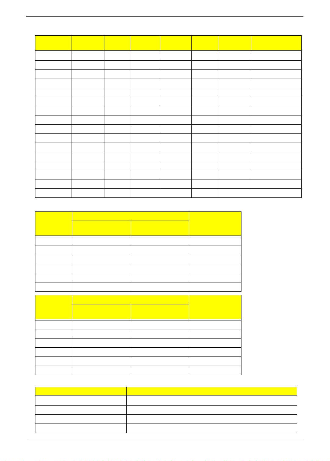
Revision History
Please refer to the table below for the updates made on Aspire Z5600/Z5610 Series service guide.
Date Chapter Updates
II
Page 3

Copyright
Copyright © 2009 by Acer Incorporated. All rights reserved. No part of this publication may be reproduced,
transmitted, transcribed, stored in a retrieval system, or translated into any language or computer language, in
any form or by any means, electronic, mechanical, magnetic, optical, chemical, manual or otherwise, without
the prior written permission of Acer Incorporated.
Disclaimer
The information in this guide is subject to change without notice.
Acer Incorporated makes no representations or warranties, either expressed or implied, with respect to the
contents hereof and specifically disclaims any warranties of merchantability or fitness for any particular
purpose. Any Acer Incorporated software described in this manual is sold or licensed "as is". Should the
programs prove defective following their purchase, the buyer (and not Acer Incorporated, its distributor, or its
dealer) assumes the entire cost of all necessary servicing, repair, and any incidental or consequential
damages resulting from any defect in the software.
Acer is a registered trademark of Acer Corporation.
Intel is a registered trademark of Intel Corporation.
Pentium and Pentium II/III are trademarks of Intel Corporation.
Other brand and product names are trademarks and/or registered trademarks of their respective holders.
III
Page 4

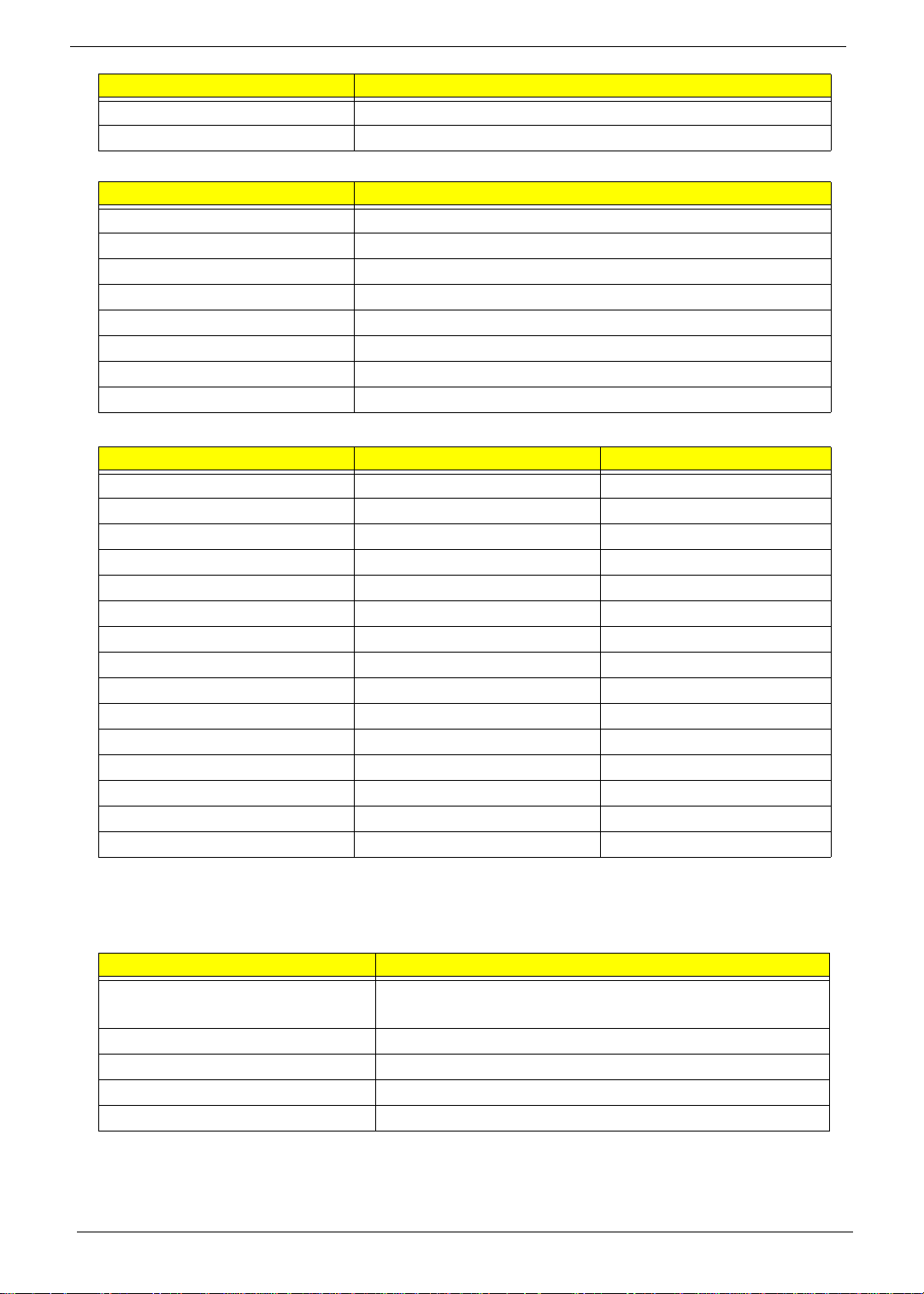
Conventions
The following conventions are used in this manual:
SCREEN MESSAGES Denotes actual messages that appear
on screen.
NOTE Gives bits and pieces of additional
information related to the current
topic.
WARNING Alerts you to any damage that might
result from doing or not doing specific
actions.
CAUTION Gives precautionary measures to
avoid possible hardware or software
problems.
IMPORTANT Reminds you to do specific actions
relevant to the accomplishment of
procedures.
IV
Page 5

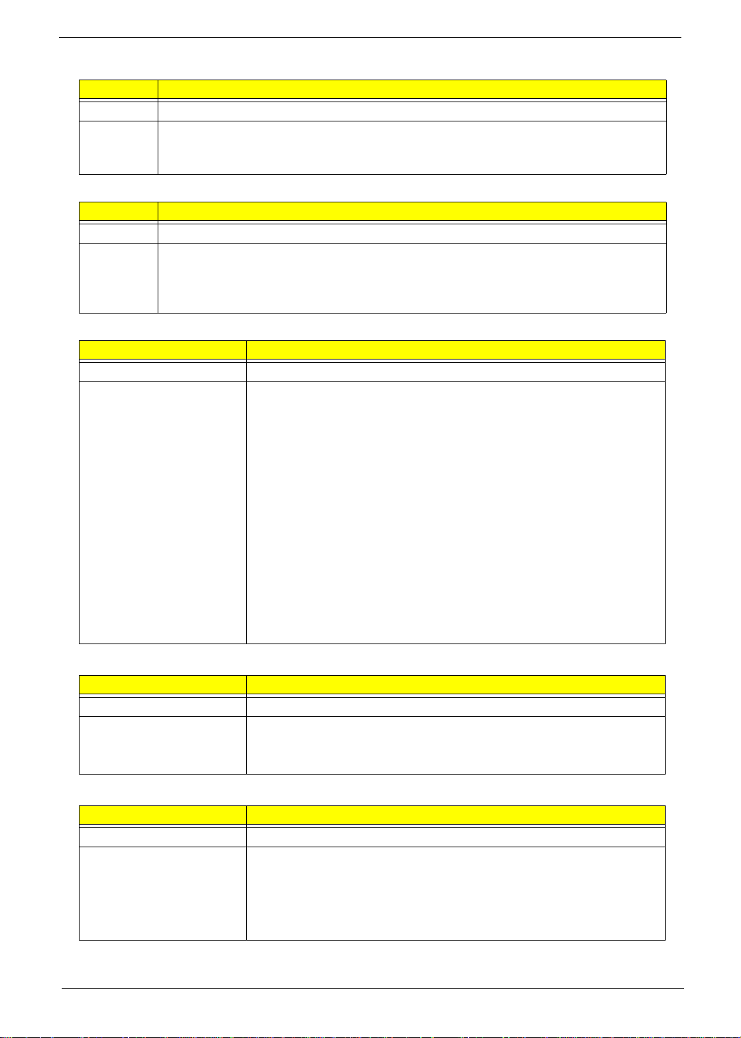
Preface
Before using this information and the product it supports, please read the following general information.
1. This Service Guide provides you with all technical information relating to the BASIC CONFIGURATION
decided for Acer's "global" product offering. To better fit local market requirements and enhance product
competitiveness, your regional office MAY have decided to extend the functionality of a machine (e.g.
add-on card, modem, or extra memory capability). These LOCALIZED FEATURES will NOT be covered
in this generic service guide. In such cases, please contact your regional offices or the responsible
personnel/channel to provide you with further technical details.
2. Please note WHEN ORDERING FRU PARTS, that you should check the most up-to-date information
available on your regional web or channel. If, for whatever reason, a part number change is made, it will
not be noted in the printed Service Guide. For ACER-AUTHORIZED SERVICE PROVIDERS, your Acer
office may have a DIFFERENT part number code to those given in the FRU list of this printed Service
Guide. You MUST use the list provided by your regional Acer office to order FRU parts for repair and
service of customer machines.
V
Page 6

VI
Page 7

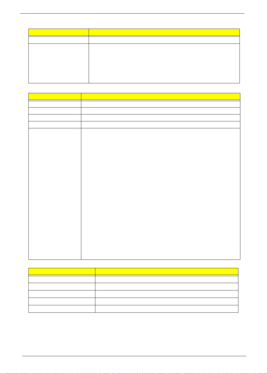
Table of Contents
System Specifications 1
Features . . . . . . . . . . . . . . . . . . . . . . . . . . . . . . . . . . . . . . . . . . . . . . . . . . . . . . . . . . . .1
System Block Diagram . . . . . . . . . . . . . . . . . . . . . . . . . . . . . . . . . . . . . . . . . . . . . . . . .3
Your Acer Computer tour . . . . . . . . . . . . . . . . . . . . . . . . . . . . . . . . . . . . . . . . . . . . . . .4
Front View . . . . . . . . . . . . . . . . . . . . . . . . . . . . . . . . . . . . . . . . . . . . . . . . . . . . . . .4
Right View . . . . . . . . . . . . . . . . . . . . . . . . . . . . . . . . . . . . . . . . . . . . . . . . . . . . . . .5
Left View . . . . . . . . . . . . . . . . . . . . . . . . . . . . . . . . . . . . . . . . . . . . . . . . . . . . . . . .6
Rear View . . . . . . . . . . . . . . . . . . . . . . . . . . . . . . . . . . . . . . . . . . . . . . . . . . . . . . .7
Using the Keyboard . . . . . . . . . . . . . . . . . . . . . . . . . . . . . . . . . . . . . . . . . . . . . . . . . . .8
Windows Keys . . . . . . . . . . . . . . . . . . . . . . . . . . . . . . . . . . . . . . . . . . . . . . . . . . .9
Hardware Specifications and Configurations . . . . . . . . . . . . . . . . . . . . . . . . . . . . . . .10
System Utilities 17
BIOS Setup Utility . . . . . . . . . . . . . . . . . . . . . . . . . . . . . . . . . . . . . . . . . . . . . . . . . . . .17
Navigating the BIOS Utility . . . . . . . . . . . . . . . . . . . . . . . . . . . . . . . . . . . . . . . . .17
Information . . . . . . . . . . . . . . . . . . . . . . . . . . . . . . . . . . . . . . . . . . . . . . . . . . . . .18
Main . . . . . . . . . . . . . . . . . . . . . . . . . . . . . . . . . . . . . . . . . . . . . . . . . . . . . . . . . .19
Advanced . . . . . . . . . . . . . . . . . . . . . . . . . . . . . . . . . . . . . . . . . . . . . . . . . . . . . .23
Security . . . . . . . . . . . . . . . . . . . . . . . . . . . . . . . . . . . . . . . . . . . . . . . . . . . . . . . .26
PC Health . . . . . . . . . . . . . . . . . . . . . . . . . . . . . . . . . . . . . . . . . . . . . . . . . . . . . .29
Power . . . . . . . . . . . . . . . . . . . . . . . . . . . . . . . . . . . . . . . . . . . . . . . . . . . . . . . . .30
Boot . . . . . . . . . . . . . . . . . . . . . . . . . . . . . . . . . . . . . . . . . . . . . . . . . . . . . . . . . . .31
Exit . . . . . . . . . . . . . . . . . . . . . . . . . . . . . . . . . . . . . . . . . . . . . . . . . . . . . . . . . . .32
Machine Disassembly and Replacement 33
Disassembly Requirements . . . . . . . . . . . . . . . . . . . . . . . . . . . . . . . . . . . . . . . . . . . .33
General Information . . . . . . . . . . . . . . . . . . . . . . . . . . . . . . . . . . . . . . . . . . . . . . . . . .33
Pre-disassembly Instructions . . . . . . . . . . . . . . . . . . . . . . . . . . . . . . . . . . . . . . .33
Disassembly Process . . . . . . . . . . . . . . . . . . . . . . . . . . . . . . . . . . . . . . . . . . . . . . . . .34
Disassembly Flowchart . . . . . . . . . . . . . . . . . . . . . . . . . . . . . . . . . . . . . . . . . . . .34
Removing the RAM Cover . . . . . . . . . . . . . . . . . . . . . . . . . . . . . . . . . . . . . . . . .35
Removing the Hinge Cover . . . . . . . . . . . . . . . . . . . . . . . . . . . . . . . . . . . . . . . . .36
Removing the RAM . . . . . . . . . . . . . . . . . . . . . . . . . . . . . . . . . . . . . . . . . . . . . . .37
Removing the Rear Covers . . . . . . . . . . . . . . . . . . . . . . . . . . . . . . . . . . . . . . . . .38
Removing the Back Cover . . . . . . . . . . . . . . . . . . . . . . . . . . . . . . . . . . . . . . . . .39
Removing the Hinge . . . . . . . . . . . . . . . . . . . . . . . . . . . . . . . . . . . . . . . . . . . . . .41
Removing the Back Frame . . . . . . . . . . . . . . . . . . . . . . . . . . . . . . . . . . . . . . . . .42
Removing the Power Supply . . . . . . . . . . . . . . . . . . . . . . . . . . . . . . . . . . . . . . . .44
Removing the HDD Module . . . . . . . . . . . . . . . . . . . . . . . . . . . . . . . . . . . . . . . .45
Removing the B-CAS Board . . . . . . . . . . . . . . . . . . . . . . . . . . . . . . . . . . . . . . . .46
Removing the SSD Module . . . . . . . . . . . . . . . . . . . . . . . . . . . . . . . . . . . . . . . . .47
Removing the Control Board . . . . . . . . . . . . . . . . . . . . . . . . . . . . . . . . . . . . . . . .48
Removing the Card Reader Board . . . . . . . . . . . . . . . . . . . . . . . . . . . . . . . . . . .49
Removing the Audio Board . . . . . . . . . . . . . . . . . . . . . . . . . . . . . . . . . . . . . . . . .50
Removing the ODD Button Board . . . . . . . . . . . . . . . . . . . . . . . . . . . . . . . . . . . .51
Removing the ODD Module . . . . . . . . . . . . . . . . . . . . . . . . . . . . . . . . . . . . . . . .52
Removing the Inverter Board . . . . . . . . . . . . . . . . . . . . . . . . . . . . . . . . . . . . . . .53
Removing the Home Button Board . . . . . . . . . . . . . . . . . . . . . . . . . . . . . . . . . . .55
Removing the Web Camera Board . . . . . . . . . . . . . . . . . . . . . . . . . . . . . . . . . . .56
Removing the TV Tuner Board . . . . . . . . . . . . . . . . . . . . . . . . . . . . . . . . . . . . . .57
Removing the WLAN Board . . . . . . . . . . . . . . . . . . . . . . . . . . . . . . . . . . . . . . . .58
Removing the CPU Fan . . . . . . . . . . . . . . . . . . . . . . . . . . . . . . . . . . . . . . . . . . .59
Removing the Thermal Module . . . . . . . . . . . . . . . . . . . . . . . . . . . . . . . . . . . . . .60
Removing the CPU . . . . . . . . . . . . . . . . . . . . . . . . . . . . . . . . . . . . . . . . . . . . . . .61
VII
Page 8

Table of Contents
Removing the Mainboard Cables . . . . . . . . . . . . . . . . . . . . . . . . . . . . . . . . . . . .62
Removing the Mainboard . . . . . . . . . . . . . . . . . . . . . . . . . . . . . . . . . . . . . . . . . .63
Removing the LCD Assembly . . . . . . . . . . . . . . . . . . . . . . . . . . . . . . . . . . . . . . .64
Removing the LCD Bracket . . . . . . . . . . . . . . . . . . . . . . . . . . . . . . . . . . . . . . . .68
Reassembly Procedure . . . . . . . . . . . . . . . . . . . . . . . . . . . . . . . . . . . . . . . . . . . . . . .69
Replacing the LCD Bracket . . . . . . . . . . . . . . . . . . . . . . . . . . . . . . . . . . . . . . . . .69
Replacing the LCD Assembly . . . . . . . . . . . . . . . . . . . . . . . . . . . . . . . . . . . . . . .70
Replacing the Mainboard . . . . . . . . . . . . . . . . . . . . . . . . . . . . . . . . . . . . . . . . . .73
Replacing the Mainboard Cables . . . . . . . . . . . . . . . . . . . . . . . . . . . . . . . . . . . .74
Replacing the CPU . . . . . . . . . . . . . . . . . . . . . . . . . . . . . . . . . . . . . . . . . . . . . . .75
Replacing the Thermal Module . . . . . . . . . . . . . . . . . . . . . . . . . . . . . . . . . . . . . .76
Replacing the CPU Fan . . . . . . . . . . . . . . . . . . . . . . . . . . . . . . . . . . . . . . . . . . .77
Replacing the WLAN Board . . . . . . . . . . . . . . . . . . . . . . . . . . . . . . . . . . . . . . . .78
Replacing the TV Tuner Board . . . . . . . . . . . . . . . . . . . . . . . . . . . . . . . . . . . . . .79
Replacing the Web Camera Board . . . . . . . . . . . . . . . . . . . . . . . . . . . . . . . . . . .80
Replacing the Home Button Board . . . . . . . . . . . . . . . . . . . . . . . . . . . . . . . . . . .81
Replacing the Inverter Board . . . . . . . . . . . . . . . . . . . . . . . . . . . . . . . . . . . . . . .82
Replacing the ODD Module . . . . . . . . . . . . . . . . . . . . . . . . . . . . . . . . . . . . . . . .84
Replacing the ODD Button Board . . . . . . . . . . . . . . . . . . . . . . . . . . . . . . . . . . . .85
Replacing the Audio Board . . . . . . . . . . . . . . . . . . . . . . . . . . . . . . . . . . . . . . . . .86
Replacing the Card Reader Board . . . . . . . . . . . . . . . . . . . . . . . . . . . . . . . . . . .87
Replacing the Control Board . . . . . . . . . . . . . . . . . . . . . . . . . . . . . . . . . . . . . . . .88
Replacing the SSD . . . . . . . . . . . . . . . . . . . . . . . . . . . . . . . . . . . . . . . . . . . . . . .89
Replacing the B-CAS Board . . . . . . . . . . . . . . . . . . . . . . . . . . . . . . . . . . . . . . . .90
Replacing the HDD Module . . . . . . . . . . . . . . . . . . . . . . . . . . . . . . . . . . . . . . . .92
Replacing the Power Supply . . . . . . . . . . . . . . . . . . . . . . . . . . . . . . . . . . . . . . . .93
Replacing the Back Frame . . . . . . . . . . . . . . . . . . . . . . . . . . . . . . . . . . . . . . . . .94
Replacing the Hinge . . . . . . . . . . . . . . . . . . . . . . . . . . . . . . . . . . . . . . . . . . . . . .96
Replacing the Back Cover . . . . . . . . . . . . . . . . . . . . . . . . . . . . . . . . . . . . . . . . .97
Replacing the Rear Covers . . . . . . . . . . . . . . . . . . . . . . . . . . . . . . . . . . . . . . . . .99
Replacing the RAM . . . . . . . . . . . . . . . . . . . . . . . . . . . . . . . . . . . . . . . . . . . . . .100
Replacing the Hinge Cover . . . . . . . . . . . . . . . . . . . . . . . . . . . . . . . . . . . . . . . .101
Replacing the RAM Cover . . . . . . . . . . . . . . . . . . . . . . . . . . . . . . . . . . . . . . . .102
Troubleshooting 103
Common Problems . . . . . . . . . . . . . . . . . . . . . . . . . . . . . . . . . . . . . . . . . . . . . . . . . .103
ODD Failure . . . . . . . . . . . . . . . . . . . . . . . . . . . . . . . . . . . . . . . . . . . . . . . . . . .104
Wireless Failure . . . . . . . . . . . . . . . . . . . . . . . . . . . . . . . . . . . . . . . . . . . . . . . .107
Camera Failure . . . . . . . . . . . . . . . . . . . . . . . . . . . . . . . . . . . . . . . . . . . . . . . . .108
Speaker Failure . . . . . . . . . . . . . . . . . . . . . . . . . . . . . . . . . . . . . . . . . . . . . . . . .109
LCD Failure . . . . . . . . . . . . . . . . . . . . . . . . . . . . . . . . . . . . . . . . . . . . . . . . . . . .111
General Troubleshooting Issues . . . . . . . . . . . . . . . . . . . . . . . . . . . . . . . . . . . .113
Intermittent Problems . . . . . . . . . . . . . . . . . . . . . . . . . . . . . . . . . . . . . . . . . . . . . . . .116
Undetermined Problems . . . . . . . . . . . . . . . . . . . . . . . . . . . . . . . . . . . . . . . . . . . . . .116
Jumper and Connector Locations 117
Top View . . . . . . . . . . . . . . . . . . . . . . . . . . . . . . . . . . . . . . . . . . . . . . . . . . . . . . . . . .117
Bottom View . . . . . . . . . . . . . . . . . . . . . . . . . . . . . . . . . . . . . . . . . . . . . . . . . . . . . . .118
Clearing Password Check and BIOS Recovery . . . . . . . . . . . . . . . . . . . . . . . . . . . .119
Clearing Password Check . . . . . . . . . . . . . . . . . . . . . . . . . . . . . . . . . . . . . . . . .119
BIOS Recovery by Crisis Disk . . . . . . . . . . . . . . . . . . . . . . . . . . . . . . . . . . . . .120
FRU (Field Replaceable Unit) List 123
Aspire Z5600/Z5610 Series Exploded Diagrams . . . . . . . . . . . . . . . . . . . . . . . . . . .124
Main Assembly . . . . . . . . . . . . . . . . . . . . . . . . . . . . . . . . . . . . . . . . . . . . . . . . .124
VIII
Page 9

Table of Contents
FRU List . . . . . . . . . . . . . . . . . . . . . . . . . . . . . . . . . . . . . . . . . . . . . . . . . . . . . .126
Screw List . . . . . . . . . . . . . . . . . . . . . . . . . . . . . . . . . . . . . . . . . . . . . . . . . . . . .134
Model Definition and Configuration 136
Aspire Z5600/Z5610 Series . . . . . . . . . . . . . . . . . . . . . . . . . . . . . . . . . . . . . . . . . . .136
Test Compatible Components 187
Microsoft® Windows® 7 Environment Test . . . . . . . . . . . . . . . . . . . . . . . . . . . . . . .188
Online Support Information 197
Index 199
IX
Page 10

Table of Contents
X
Page 11

System Specifications
Features
Below is a brief summary of the computer’s many features:
Operating System
• Genuine Windows® 7 Home Premium (Touch Pack)*
Platform
• Intel Core™2 Quad Processor*
• Intel Core™2 Duo Processor*
• Intel Pentium Processor*
• Intel® Celeron® processor*
• Intel Eaglelake G45(B/S)+ICH10(B/S)*
Chapter 1
Dimensions
• 570 (W) x 484.0 (H) x 84.6 (D) mm
System Memory
• Up to 8 GB of DDR3 1066/1333 MHz (dual-channel support on four DIMMs)*
Display
• 23" Full HD 1920 x 1080 pixel resolution, high brightness TFT LCD
• 16:9 aspect ratio
• 5 ms response time
• 16.7 million colors
• 1000:1 (ACM) contrast ratio
• Integrated Windows® 7 compliant multi-touch capable optical solution
TV Tuner
• Hybrid analog (NTSC/PAL/SECAM) and digital (DVB-T or ATSC format) TV -tuner card, supporting
software MPEG-2 stream encoding*
Storage subsystem
• Hard Drive
• SATA 3 Gb/s hard disk up to 1 TB*
• SATA 3 Gb/s hard disk up to 1 TB with SSD NAND flash module up to 64 GB*
• Desktop Optical Disk Drive
Chapter 1 1
Page 12

• SuperMulti with Labelflash™ technologyDVD-ROM*
Communication
• Built-in 1 MP high-def webcam with 1280 x 800 resolution image capture
• Built-in microphone
• Gigabit Ethernet, Wake-on-LAN ready
• WLAN*
• 802.11b/g/Draft-N
• WPAN*
• Bluetooth® 2.1+EDR (Enhanced Data Rate)
Graphics
• Intel® GMA X4500HD (Intel® G45) (Aspire Z5600)
• ATI Radeon™ HD 4670 with 1 GB DDR3 Memory (Aspire Z5610)
• ATI Radeon™ HD 4570 with 512 MB DDR2 Memory (Aspire Z5610)
I/O interface
• Two USB 2.0 ports
• Multi-in-1 card reader
• High-definition headphone and microphone jacks
• Ambient light switch
• BCAS card Reader Slot (Japan only)
• Four USB 2.0 ports
• DC-in jack
• Ethernet (RJ-45) port
• Four audio ports
• eSATA port
• IR blaster port2 (bundle with TV tuner card)
• TV-tuner port2
Environment
• Temperature:
• Operating: 5 °C to 35 °C
• Non-operating: -20 °C to 65 °C
• Humidity (non-condensing):
• Operating: 20% to 80%
• Non-operating: 20% to 80%
NOTE: Items marked with * denote only selected models.
NOTE: The specifications listed above are for reference only. The exact configuration of your PC depends on
the model purchased.
2 Chapter 1
Page 13
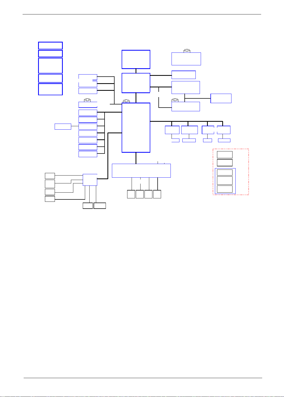
System Block Diagram
VCC_CORE
GMCH_CORE
VCC1.1
VCC1.2
VCC1.5
1.5VSUS
VCC3
3V_STBY
VCC5
5V_STBY
+12V
HP
Page 30
MIC IN
Page 30
INT SPK
Page 29
DMIC IN
Page 30
BT KB/Mouse
Page 27
SATA - HDD(2.5)
Page 22
SATA - HDD(3.5)
Page 22
SATA - ODD
Page 22
Y4 25MHz/20pF/30ppm
eSATA
Page 22
WLAN
Page 25
Camera
Page 19
Bluetooth
Page 26
USB*4(Rear)
Page 27
TV
Page 25
USB*2(Side)
Page 26
Touch Screen
Page 27
AUDIO CODEC
ALC888S-VC2
Page 29
LINE IN 5.1 Channel
USB-10
USB-1
USB-2
USB-6,7
8,9
USB-11
USB-3,5
USB-0
SATA 4
SATA 1
SATA 2
SATA 3
USB 2.0
Azalia
Intel
Yorkfield/Wolfdale
Q9000/E8000
LGA775
NB
Eaglelake
G45/P43
1254 pin
Y2 32.768KHZ
SB
ICH10
676 pin
32.768KHz
Page 10,11,12,13
LPC
ITE8512
IR
Blaster
Page 3
Page 3,4
FSB(800/1067/1333HZ)
Page 5,7,8,9
DMI
FLASH
FAN
ROM
Page 28 Page 28
Page 26
14.318MHz
800/1067 MHZ DDR III
PCI-E 2.0 16X
PCI-Express 1X
Y5 32.768KHz
CIR
CH A: DDRIII-UDIMM0/1
CH B: DDRIII-UDIMM0/1
MXM CONNECTOR
Y3 IV@14.318MHZ
SDVO
14.318MHz
PCIE-2 PCIE-1
MINI CARD-1
WLAN
Page 25
Page 26
Y1 14.318MHZ
CLOCK GENERATOR
CK505
CV193
Page 14,15,16,17
LVDS
LVDS Transmitter
CH7308B
PCIE-3
MINI CARD-2
TV card
Page 25
TV antennaWLAN antenna
Page 2
Page 18
Page 19
LAN
RTL8111DL
25MHz
Page 26
RJ45
LCD PANEL
23" Full HD
PCIE-4
Card Reader
JMB385
Media Slot
MXM module
B-CAS board
Card Reader
HP/MIC
Light SW
Power button
LED
Page 27
314 pin
10 pin
20 pin
10 pin
Daughter
Board
TBD
Chapter 1 3
Page 14
Your Acer Computer tour
After knowing your computer features, let us show you around your new computer.
IMPORTANT:Your computer’s hardware options, port locations, and indicators may vary from this illustration.
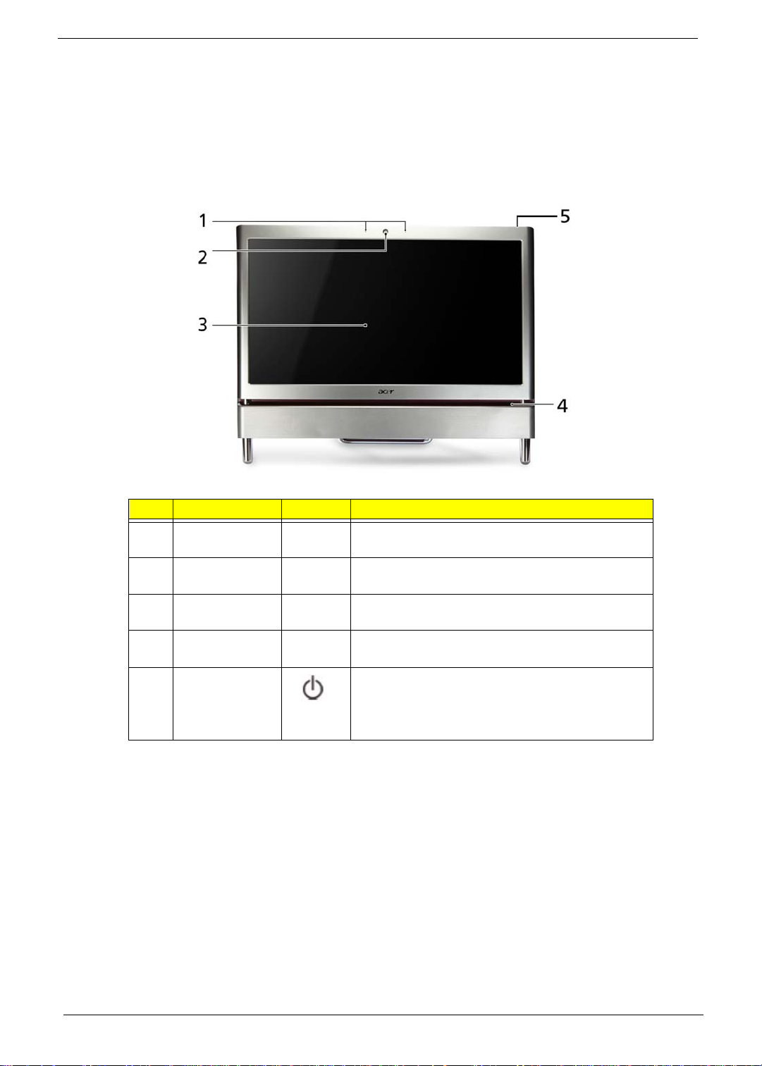
Front View
No. Component Icon Description
1 Microphone Use to talk through when making Voice over
Internet Protocol (VoIP) calls.
2 HD webcam Use to let others see who they are communicati ng
with when making VoIP calls.
3 Display screen Also called Liquid-Crystal Display (LCD), displays
computer output.
4Acer
TouchPortal
5 Power Button Press this button to turn the power on or off.
Access and control some of the handy features of
your new computer.
You can also configure the power button to
operate in Standby/Resume mode or
Hibernate mode.
4 Chapter 1
Page 15
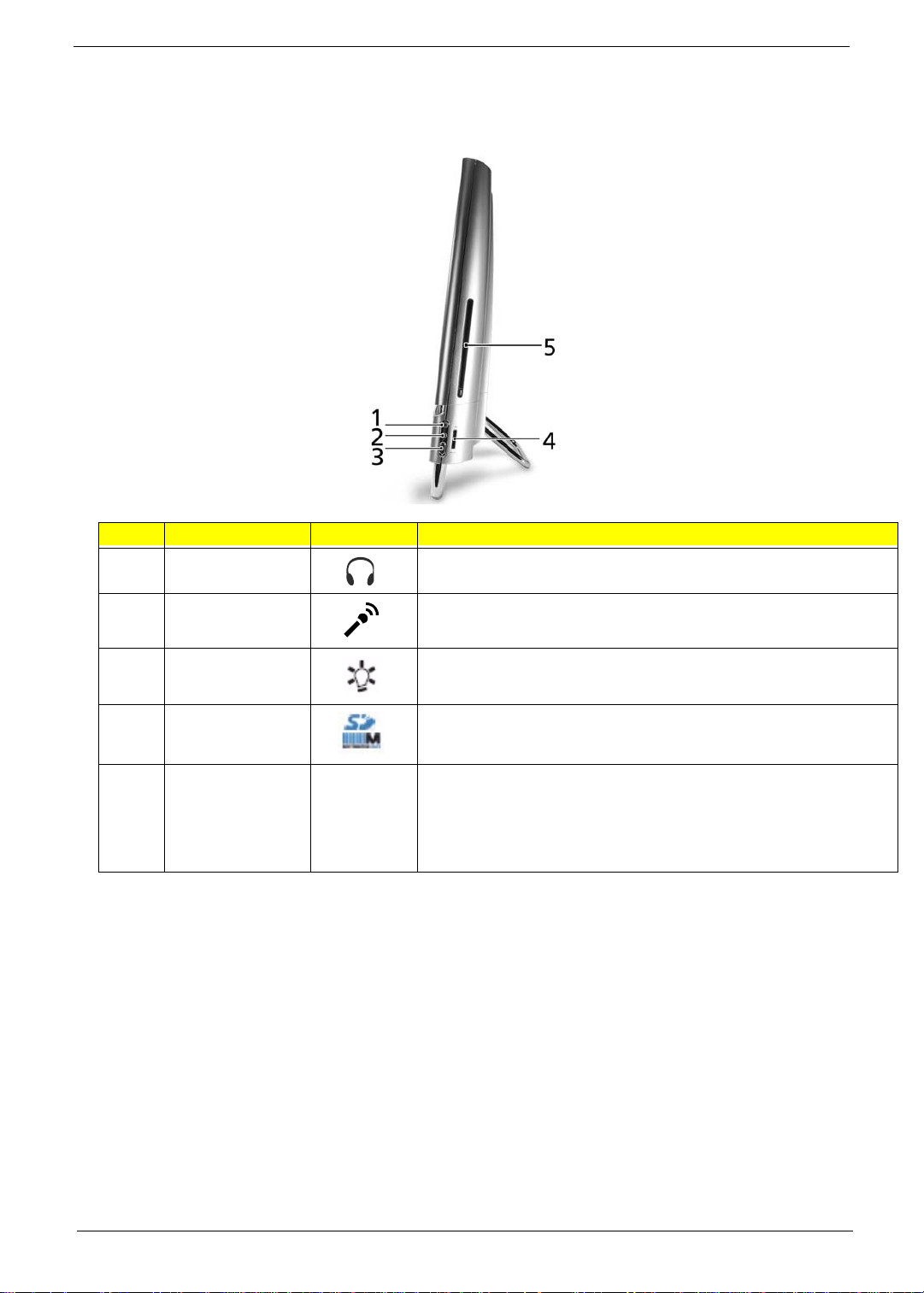
Right View
IMPORTANT:Your computer’s hardware options, port locations, and indicators may vary from this illustration.
No. Component Icon Description
1 Headphone jack
(white plug)
2 Microphone jack
(pink plug)
Plug powered, analog front speakers, an external amplifier, or
headphones into this jack.
Plug a microphone into this jack.
3 Illumination Toggle
Switch
4 Memory card
reader
5 Optical Disk Drive Use this drive to listen to audio CDs, install games and programs,
Insert a memory card from a digital camera, MP3 player, PDA,
cellular telephone, or other device into the memory card reader.
watch DVDs, and
store large files onto recordable discs (depending on drive type). This
drive may be
a CD, recordable CD, DVD, or recordable DVD.
Chapter 1 5
Page 16
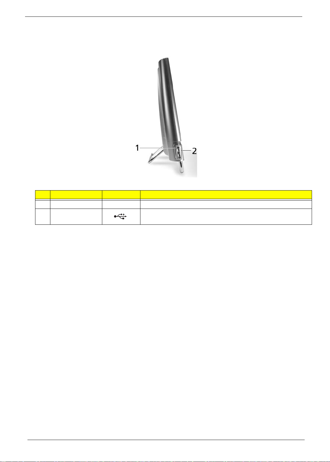
Left View
IMPORTANT:Your computer’s hardware options, port locations, and indicators may vary from this illustration.
No. Component Icon Description
1 B-CAS reader Subscription service available for select models only.
2 USB 2.0 port Plug USB (Universal Serial Bus) devices (such as a USB external
drive, printer, scanner, camera, keyboard, or mouse) into this port.
6 Chapter 1
Page 17
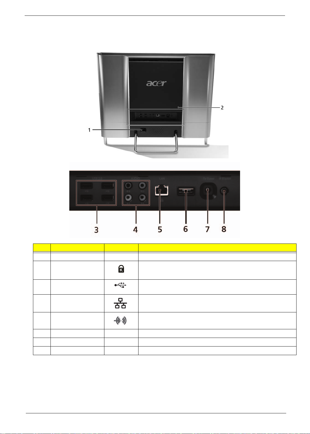
Rear View
IMPORTANT:Your computer’s hardware options, port locations, and indicators may vary from this illustration.
No. Component Icon Description
1 Power connector Plug the power cord into this connector.
2 Kensington™ lock
slot
3 USB ports Plug USB (Universal Serial Bus) devices (such as a USB printer,
4 Ethernet (network)
jack
5 Line-out/Speaker-
out jack
6 eSATA port Plug external hard drives into this connector.
7 TV Tuner Allows a TV Tuner to be connected to the system.
8 IR port Allows data transfer between the desktop and a mobile device.
Secure your computer to an object by connecting a Kensington
cable lock to this slot.
scanner, camera, keyboard, or mouse) into these ports.
Plug an Ethernet network cable or a device (such as a DSL or
cable modem for a broadband Internet connection) into this jack.
Plug an line output to an amplifier or entertainment system into
this jack for sound output.
Chapter 1 7
Page 18
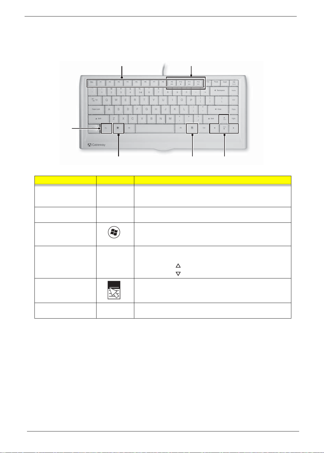
Using the Keyboard
Windows key
Application
key
Navigation keys
Function keys
Audio playback keys
Fn key
The keyboard has several different types of keys and buttons as shown below.
Feature Icon Description
Function keys Press these keys to start program actions. Each program uses
different function keys for different purposes. See the program
documentation to find out more about the function key actions.
Audio playback keys Press these keys to play your audio files and to adjust the
volume.
Windows key Press this key to open the Windows Start menu.
This key can also be used in combination with other keys to
open utilities. See “Windows Keys” on page 9.
Fn key Press this key in combination with keys that have alternate
functions defined, such as the F9-F12 keys.
Press <Fn> + < > to increase the brightness of the display.
Press <Fn> + < > to decrease the brightness of the display.
Application key Press this key to access shortcut menus and help assistants in
Windows.
Navigation keys Press these keys to move the cursor and to copy, cut, and
paste objects.
8 Chapter 1
Page 19
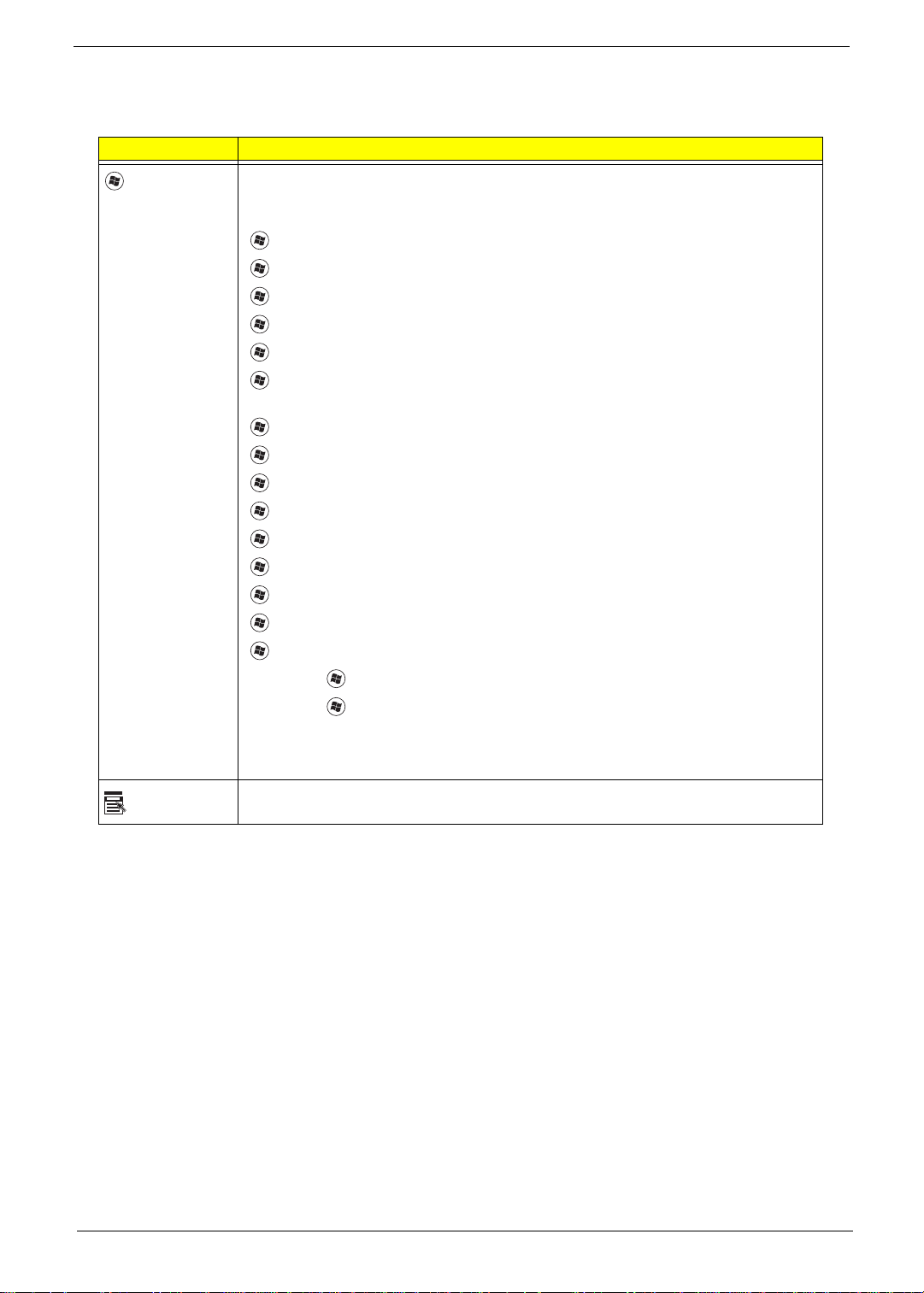
Windows Keys
The keyboard has two keys that perform Windows-specific functions.
Key Description
Windows key Pressed alone, this key has the same effect as clicking on the Windows Start button;
it launches the Start menu. It can also be used with other keys to provide a variety of
functions:
<>: Open or close the S tart menu
<> + <D>: Display the desktop
<> + <E>: Open Windows Explore
<> + <F>: Search for a file or folder
<> + <G>: Cycle through Sidebar gadgets
<> + <L>: Lock your computer (if you are connected to a network domain), or
switch users (if you're not connected to a network domain)
<> + <M>: Minimizes all windows
<> + <R>: Open the Run dialog box
<> + <T>: Cycle through programs on the taskbar
<> + <U>: Open Ease of Access Center
<> + <X>: Open Windows Mobility Center
<> + <BREAK>: Display the System Properties dialog box
<> + <SHIFT+M>: Restore minimized windows to the desktop
<> + <TAB>: Cycle through programs on the taskbar by using Windows Flip 3-D
<> + <SPACEBAR>: Bring all gadgets to the front and select Windows Sidebar
Application
key
<CTRL> +
<CTRL> + <> + <TAB>: Use the arrow keys to cycle through programs on the
Note: Depending on your edition of Windows 7, some shortcuts may not function as
This key has the same effect as clicking the right mouse button; it opens the
application's context menu.
<> + <F>: Search for computers (if you are on a network)
taskbar by using Windows Flip 3-D
described.
Chapter 1 9
Page 20
Hardware Specifications and Configurations
Processor
Item Specification
CPU type
Core Logic
• Intel Core™2 Quad Processor*
• Intel Core™2 Duo Processor*
• Intel Pentium Processor*
• Intel® Celeron® processor*
• North Bridge (Eaglelake G45)
• G TL+ interface (Front-side bus)
• Support Intel Yorkfield/Wolfdale Processor
• 800/1066/1333MHz transfer rate processor bus speed
• Integrated DRAM controller
• Dual-channel DDR3 SDRAM interface.
• Unified Memory Architecture, with 128 MB to 256MB of
the main memory configurable as display memory.
• Asynchronous FSB and Memory Controller.
• Supports Dual channel 800/1066 DDR3 SDRAM.
• Max 8GB memory addressability, for faster system.
• Serial ATA
• Support maximum four SATA 3.0Gb/s ports..
• South Bridge (ICH10)PCI bus Interface
• Supports PCI bus at 33MHz
• PCI Rev.2.3 specification support.
• Support for 64 bit addressing on PCI using DAC
protocol.SMBus: SM Bus Rev.2.0 compliant.
• Support Power management
• ACPI Specification 3.0 compliant power management
scheme.
• ACPI-defined power states(C1, S1, S3, S4, S5 for
Desktop)
• ACPI-defined power states(C1~C4, S1, S3~S5 for Mobile)
• ACPI Power Management Timer
• SMI# generation
• Low Pin Count(LPC) host interface
• PCI Express Interface
• Support PCI Express 1.1
• 6 PCI Express root ports
• Support for full 2.5 Gb/s bandwidth in each direction per
x1 lane
CPU Package Flip-Chip Land Grid Array (FC-LGA8) technology
CPU Core Voltage 1.196 ±0.748
10 Chapter 1
Page 21
Processor Specifications
Processor
#
E2220 2.4 GHz 2 800 65 W 1MB LGA KC.22201.DEM
E5200 2.5 GHz 2 800 65 W 2MB LGA KC.52001.DEM
E5300 2.6 GHz 2 800 65 W 2MB LGA KC.53001.DEM
E5400 2.7 GHz 2 800 65 W 2MB LGA KC.54001.DEM
E6300 2.8 GHz 2 1066 65 W 2 MB LGA KC.63001.DEM
E6500 2.93 GHz 2 1066 65 W 2 MB LGA KC.65001.DEM
E7300 2.66 GHz 2 1066 65 W 3 MB LGA KC.73001.DE0
E7400 2.8 GHz 2 1066 65 W 3 MB LGA KC.74001.DE0
E7500 2.93 GHz 2 1066 65 W 3 MB LGA KC.75001.DE0
E7600 3.06 GHz 2 1066 65 W 3 MB LGA KC.76001.DE0
Q8200s 2.33 GHz 4 1333 65 W 4 MB LGA KC.82001.QQS
E8400 3.0 GHz 2 1333 65 W 6 MB LGA KC.84001.DEE
Q8400s 2.66 GHz 4 1333 65 W 4 MB LGA KC.84001.QQS
E8500 3.16 GHz 2 1333 65 W 6 MB LGA KC.85001.DEE
E8600 3.33 GHz 2 1333 65 W 6 MB LGA KC.86001.DEE
Q9400s 2.66 GHz 4 1333 65 W 6 MB LGA KC.94001.QQS
CPU Fan True Value Table
Step
1 45 38 2100
2 50 46 2500
3 58 52 2800
4 64 59 3100
Throttling 68 12
Shut Down 75 12
CPU
Speed
Cores
CPU Temperature
FAN on
(°C)
Bus
Speed
FAN off
(°C)
Power
Cache
Size
CPU Fan RPM
Package Acer P/N
VGA Temperature
Step
1 44 38 2500
2 49 45 3000
3 55 50 3600
4 62 58 4000
Throttling 90 12
Shut Down 100 12
BIOS
BIOS vendor Phoenix BIOS
BIOS Version R01-A1
BIOS ROM type SPI interface to serial flash memory, SOP8 package
BIOS ROM size 8 MB
Chapter 1 11
FAN on
(°C)
Item Specification
FAN off
(°C)
VGA Fan
Voltage
Page 22
Item Specification
Supported protocols SMBIOS 2.4
BIOS password control Supervisor only
System Memory
Item Specification
Memory controller Built in
Memory size Non onboard
DIMM socket number 4
Supports memory size per socket 2 GB
Supports maximum memory size 8 GB
Supports DIMM type DDR3 SDRAM
Supports DIMM Speed 800/1066MHz
Supports DIMM voltage 1.5V
Memory Combinations
Slot 1 Slot 2 Total Memory
0MB 512MB 512MB
0MB 1024MB 1024MB
0MB 2048MB 2048MB
512MB 512MB 1024MB
512MB 1024MB 1536MB
512MB 2048MB 2560MB
1024MB 0MB 1024MB
1024MB 512MB 1536MB
1024MB 1024MB 2048MB
1024MB 2048MB 3072MB
2048MB 0MB 2048MB
2048MB 512MB 2560MB
2048MB 1024MB 3072MB
2048MB 2048MB 4096MB
4096MB 4096MB 8192MB
NOTE: Above table lists some system memory configurations. You may combine DIMMs with various
capacities to form other combinations. On above table, the configuration of slot 1 and slot 2 could be
reversed.
System Board Major Chips
Item Controller
Core logic
• EL8 implement Intel Yorkfield/Wolfdale Processor
• Eaglelake G45 + ICH10
LAN RTL811 1DL
WLAN Support Mini PCIE , USB wireless LAN
Audio Codec ALC888S
Keyboard ITE8512-NX embedded
12 Chapter 1
Page 23
NorthBridge Chipset
Item Specification
Chipset Eaglelake G45
Features
• GTL+ interface (Front-side bus)
• Support Intel Yorkfield/Wolfdale Processor
• 800/1066/1333MHz transfer rate processor bus speed
SouthBridge Chipset
Item Specification
Chipset ICH10
Features
• PCI bus Interface
• Supports PCI bus at 33MHz
• PCI Rev.2.3 specification support.
• Support for 64 bit addressing on PCI using DAC protocol.
Card Reader
Item Specification
Chipset JMB385 (SD, SDHC, MMC, MS, MS pro slot)
Features
• Compliant with PCI Express Base Spec. Revision 1.1
• Compliant with SD Spec. Part 1 Physical Layer Spec. Version 2.00
• Compliant with SD Spec. Part A2 SD Host Controller Standard Spec.
Version 2.00
• Compliant with SD Spec. Part E1 SDIO Spec. Version 2.00
• Compliant with SD Spec. Part 2 File System Spec. Version 2.00
• Compliant with MultiMediaCard System Spec. Version 4.2
• Compliant with Memory Stick St andard Format Spec. Version 1.43-00
• Compliant with Memory Stick Standard Memory Stick PRO Format
Spec. - without security spec. - Version 1.02-00
• Compliant with Memory Stick Pro-HG Duo Spec. Version 1.00
• Compliant with xD-Picture Card Spec. Version 1.20
• Compliant with xD-Picture Card Host Guideline Version 1.20
• Compliant with xD-Picture Card Format Spec. V ersion 1.11
USB 2.0
Item Specification
Chipset SB ICH10 embedded
Features
• USB host interface with support for 12USB ports
• 6 UHCI host controllers
• 2 EHCI high-speed USB2.0 Host controller
SATA Interface
Item Specification
Chipset ICH10 embedded
Features • Fast SATA, 4 ports:
• Support 3.5" HDD via SATA interface
• Support SSD HDD via SATA interface
• Support ODD via SATA interface
• Support eSATA via SATA interface
Chapter 1 13
Page 24
USB
Item Specification
Chipset ICH10 embedded
Features
• Using 6 USB2.0 Ports for Base connector
• Using 1 USB2.0 Port for PCIE/WLAN
• Using 1 USB2.0 Port for PCIE/TV
• Using 1 USB2.0 Port for Webcam
• Using 1 USB2.0 Port for Bluetooth
• Using 1 USB2.0 Port for Touch screen
LAN Interface
Item Specification
LAN Chipset Realtek RTL8111DL
Supports LAN protocol 10/100/1000M Fast Ethernet
LAN connector type RJ-45
LAN connector location Main Board
Features
• Integrated 10/100/1000N transceiver
• Auto-Negotiation with Next Page capability
• Supports PCI Express™ 1.1
• Supports pair swap/polarity/skew correction
• Crossover Detection & Auto-Correction
• Wake-on-LAN and remote wake-up support
• Microsoft® NDIS5, NDIS6 Checksum Offload (IPv4, IPv6, TCP, UDP) and
Segmentation Task-offload (Large send v1 and Large send v2) support
• Supports Full Duplex flow control (IEEE 802.3x)
• Supports jumbo frame to 9K bytes
• Fully compliant with IEEE 802.3, IEEE 802.3u, IEEE 802.3ab
• Supports IEEE 802.1P Layer 2 Priority Encoding
• Supports IEEE 802.1Q VLAN tagging
• Embedded OTP memory can replace the external EEPROM
• Serial EEPROM
• Transmit/Receive on-chip buffer support
• Supports power down/link down power saving
• Built-in Switching regulator
• Supports PCI MSI (Message Signaled Interrupt) and MSI-X
• Supports quad core Receive-Side Scaling (RSS)
• Embeds an adaptive equalizer in PCI express PHY (PCB traces to reach 40 inches)
• Supports Deep Slumber Mode (DSM) power saving feature
• Customized LEDs
• 64-pin QFN package (RTL8111D) and 48-pin LQFP (RTL8111DL) Green package
Audio Interface
Item Specification
Audio Controller ALC888S
Audio onboard or optional Onboard
Mono or Stereo Stereo
Resolution Wide range (-80 dB ~ +42 dB) volume control with 1.5 dB resolution
Compatibility EAX 1.0 and 2.0, Direct Sound 3D, I3DL2
14 Chapter 1
Page 25

Item Specification
Sampling Rate • DACs with 97dB SNR
• ADCs with 90dB SNR
• Internal Speaker(5WX2)
• Line out 5.1 Channel
• Head Phone out , MIC In , Digital MIC In
• Software Sound Volume Control
• Software Beep Volume control
Internal Microphone Yes
Chapter 1 15
Page 26

16 Chapter 1
Page 27

Chapter 2
System Utilities
BIOS Setup Utility
The BIOS Setup Utility is a hardware configuration program built into your computer’s BIOS (Basic Input/
Output System).
Y our computer is already properly configured and optimized, and you do not need to run this utility . However, if
you encounter configuration problems, you may need to run Setup. Please also refer to Chapter 4
Troubleshooting when problem arises.
To activate the BIOS Utility, press F2 during POST (when “Press <F2> to enter Setup” message is prompted
on the bottom of screen).
Press <F12> during POST to enter multi-boot menu. In this menu, user can change boot device without
entering BIOS SETUP Utility.
Navigating the BIOS Utility
There are six menu options: Information, Main, Advanced, Security, Boot, and Exit.
Follow these instructions:
• To choose a menu, use the left and right arrow keys.
• To choose an item, use the up and down arrow keys.
• To change the value of a parameter, press F5 or F6.
• A plus sign (+) indicates the item has sub-items. Press Enter to expand this item.
• Press Esc while you are in any of the menu options to go to the Exit menu.
• In any menu, you can load default settings by pressing F9. You can also press F10 to save any
changes made and exit the BIOS Setup Utility.
NOTE: You can change the value of a parameter if it is enclosed in square brackets. Navigation keys for a
particular menu are shown on the bottom of the screen. Help for parameters are found in the Item
Specific Help part of the screen. Read this carefully when making changes to parameter values. Please
note that system information is subject to different models.
Chapter 2 17
Page 28
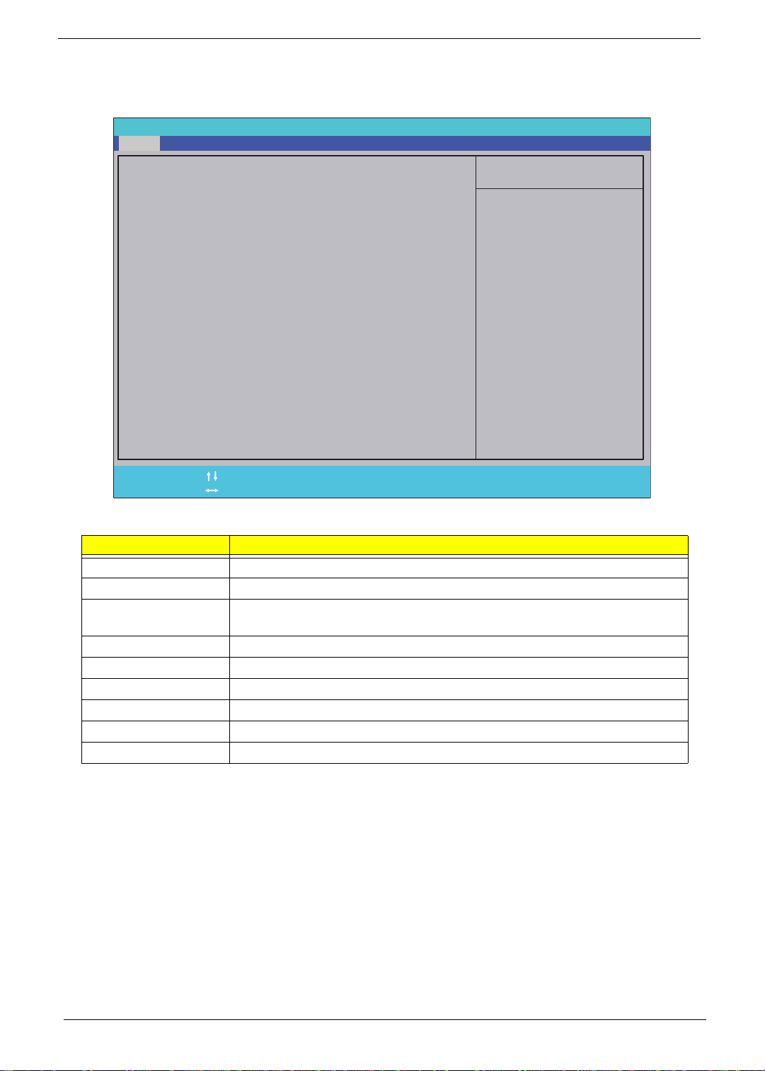
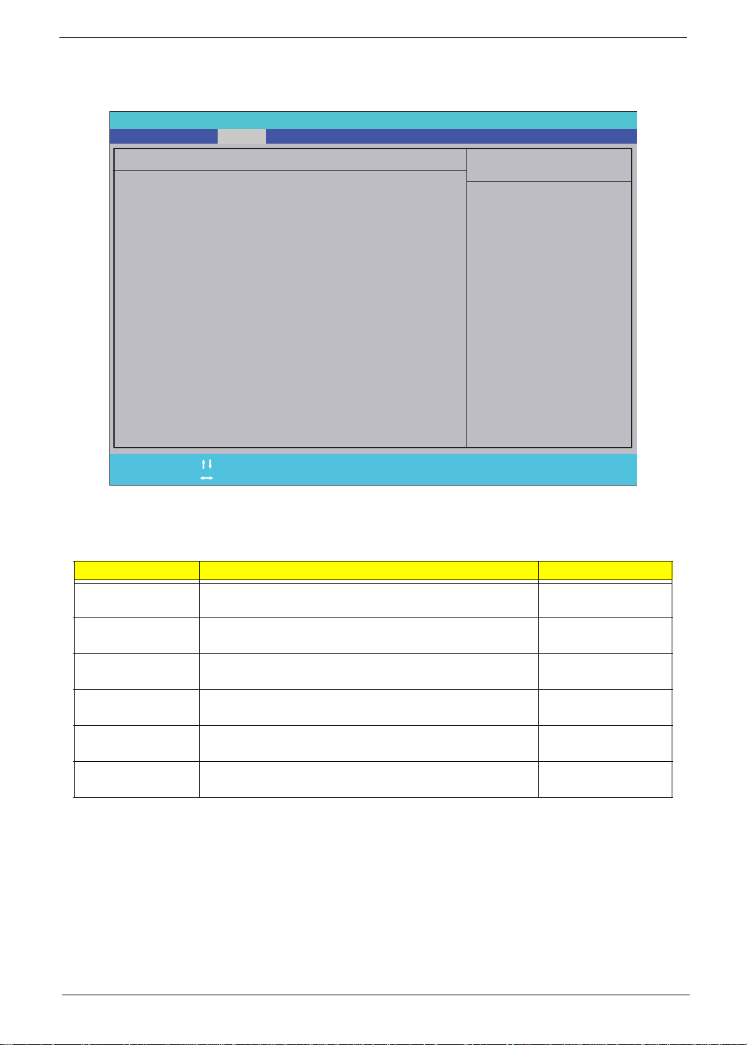
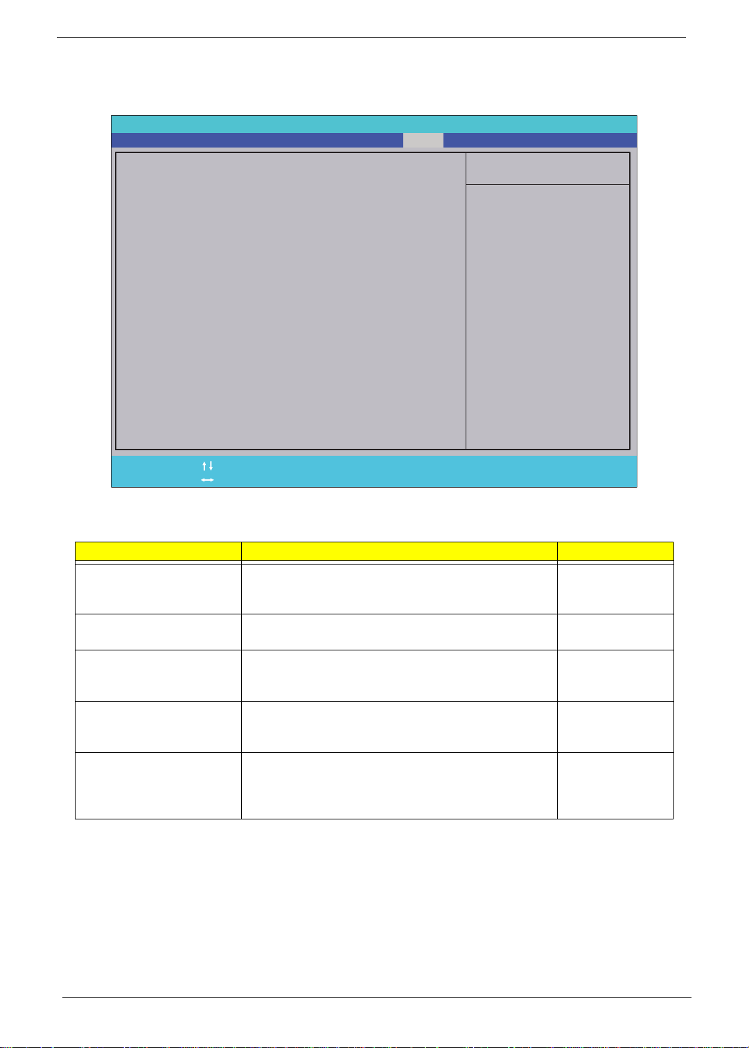
Information
The Information screen displays a summary of your computer hardware information.
PhoenixBIOS Setup Utility
Main Boot
Processor Type
SecurityInfo Advanced Power
Pentium(R) Dual-Core CPU
E5200 @ 2.50GHz
Processor Speed
System Memory:
System Manufacturer:
Product Name:
2.50 GHz
2048 MB
Acer
Aspire Z5610
System Serial Number:
System BIOS Version:
BIOS Release Date:
P0.19
08/26/2009
Asset Tag Number:
PC Health
All items on this menu
cannot be modified in
user mode. If any
items require changes,
please consult your
system Supervisor.
Exit
Item Specific Help
Help
F1
Exit
Esc
NOTE: The system information is subject to different models.
Parameter Description
Processor Type This field shows the system processor type.
Processor Speed This field shows the speed of the processor.
System Memory This field reports the memory size of the system. Memory size on this model is
System Manufacturer This field displays the manufacturer of this system.
Product Name This field shows product name of the system.
System Serial Number This field displays the serial number of this unit.
System BIOS Version This field displays system BIOS version.
BIOS Release Date This field displays the release date of the system BIOS.
Asset Tag Number This field displays the as set tag number of the system.
Select Item
Select Menu
fixed to 2048 MB.
-/+
Press Enter Press EnterF9F10
Change Values
Setup Defaults
Save and Exit
18 Chapter 2
Page 29

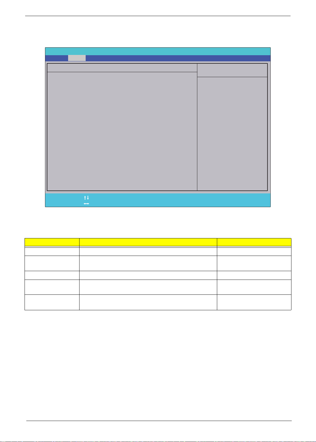
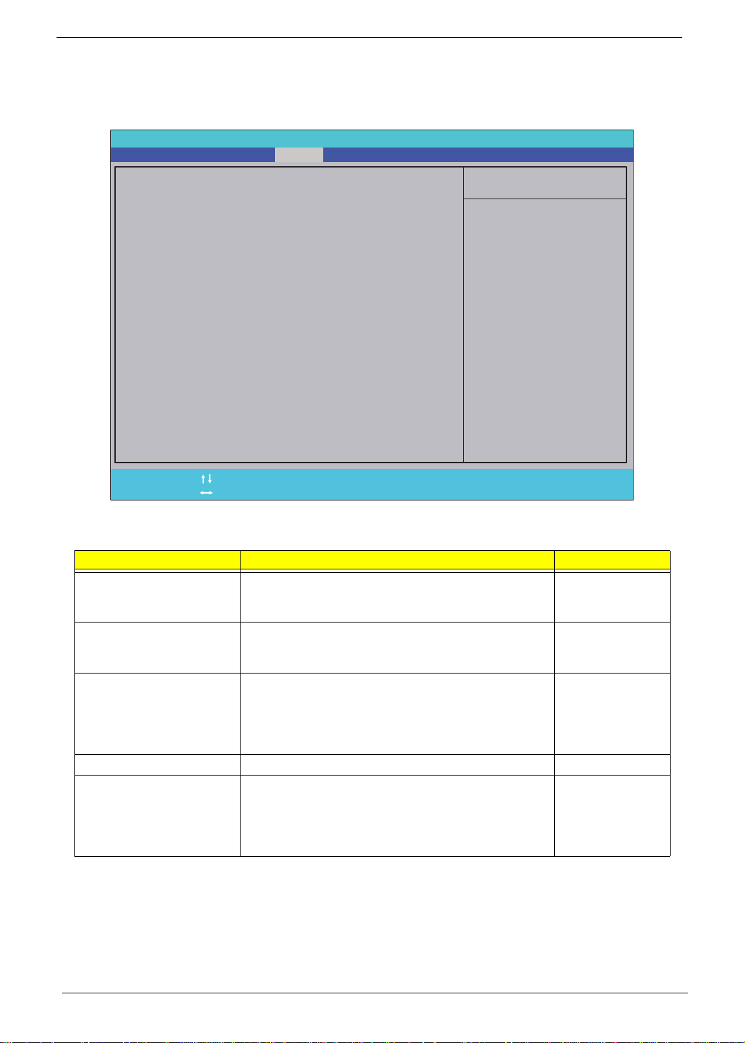
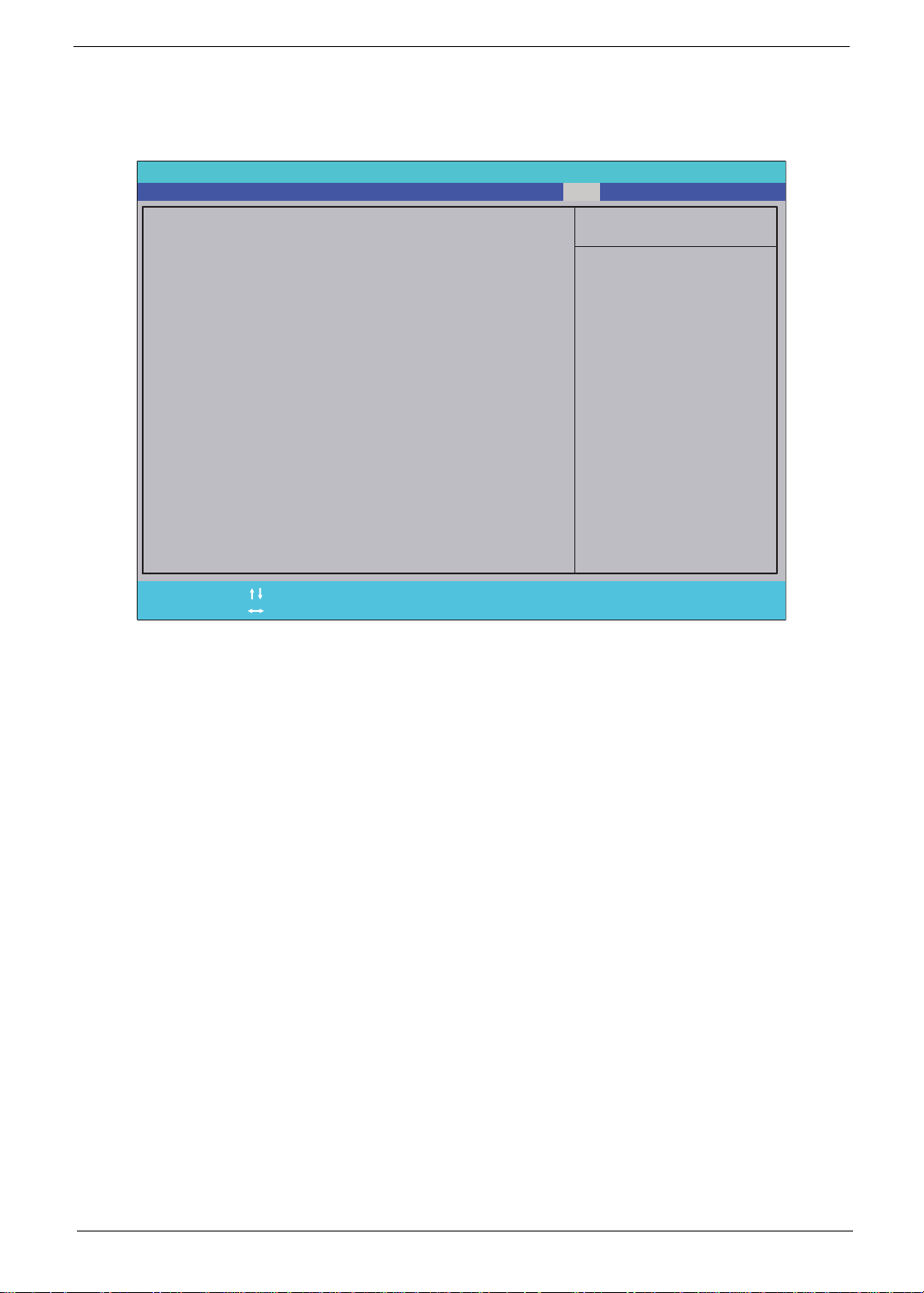
Main
The Main screen allows the user to set the system time and date as well as enable and disable boot options.
PhoenixBIOS Setup Utility
Main Boot
System Date:
System Time:
System Time:
SATA Port 1
SATA Port 1
SATA Port 2
SATA Port 2
SATA Port 4
SATA Port 4
SecurityInfo Advanced
PC Health
[08/26/2009]
[10:10:30]
[320GB SATA1]
[320GB SATA1]
[CD-ROM]
[CD-ROM]
[None]
[None]
Power
Exit
Item Specific Help
<Tab>, <Shift+Tab>, or
<Enter> selects field.
Quick Boot:
Quick Boot:
Quiet Boot:
Quiet Boot:
Bootup Num-Lock:
Bootup Num-Lock:
Boot Sector Virus Protection:
Boot Sector Virus Protection:
Halt On:
Halt On:
[Enabled]
[Enabled]
[On]
[Disabled]
[All,But KeyBoard]
Help
F1
Exit
Es c
NOTE: The screen above is for your reference only. Actual values may differ.
The table below describes the parameters in this screen. Settings in boldface are the default parameter
settings.
Parameter Description Format/Option
System Date Sets the system date.
System Time Sets the system time. The hours are displayed with 24-
SATA Port 1 This field displays SATA type. N/A
SATA Port 2 This field displays SATA type. N/A
SATA Port 4 This field displays SATA type. N/A
Quick Boot Allows startup to skip certain tests while booting,
Quiet Boot Allows startup to skip normal POST messages while
Bootup Num Lock Set Num-Lock to on or off automatically during boot. Option: Off or On
Boot Sector VIrus
Protection
Halt On Prompts the user when errors occur during boot up
Select Item
Select Menu
NOTE: If a CMOS checksum error or CMOS battery
loss occurs, set date to Jan 01 2009.
hour format.
NOTE: If a CMOS checksum error or CMOS battery
loss occurs, set time to 12:00:00.
decreasing the time needed to boot the system.
booting, decreasing the time needed to boot the
system.
Write protects the Boot Sector. Option: Enabled or
process.
NOTE: Selecting All, But KeyBoard halts the system
for all errors excluding keyboard errors.
-/ +
Pre ss En ter Pre ss En ter
Change Values
Setup Defaults
F9
Save and Exit
F1 0
Format MM/DD/YYYY
(month/day/year)
Format: HH:MM:SS
(hour:minute:second)
Option: Enabled or
Disabled
Option: Enabled or
Disabled
Disabled
Option: All Errors, No
Errors, All, But KeyBoard
Chapter 2 19
Page 30

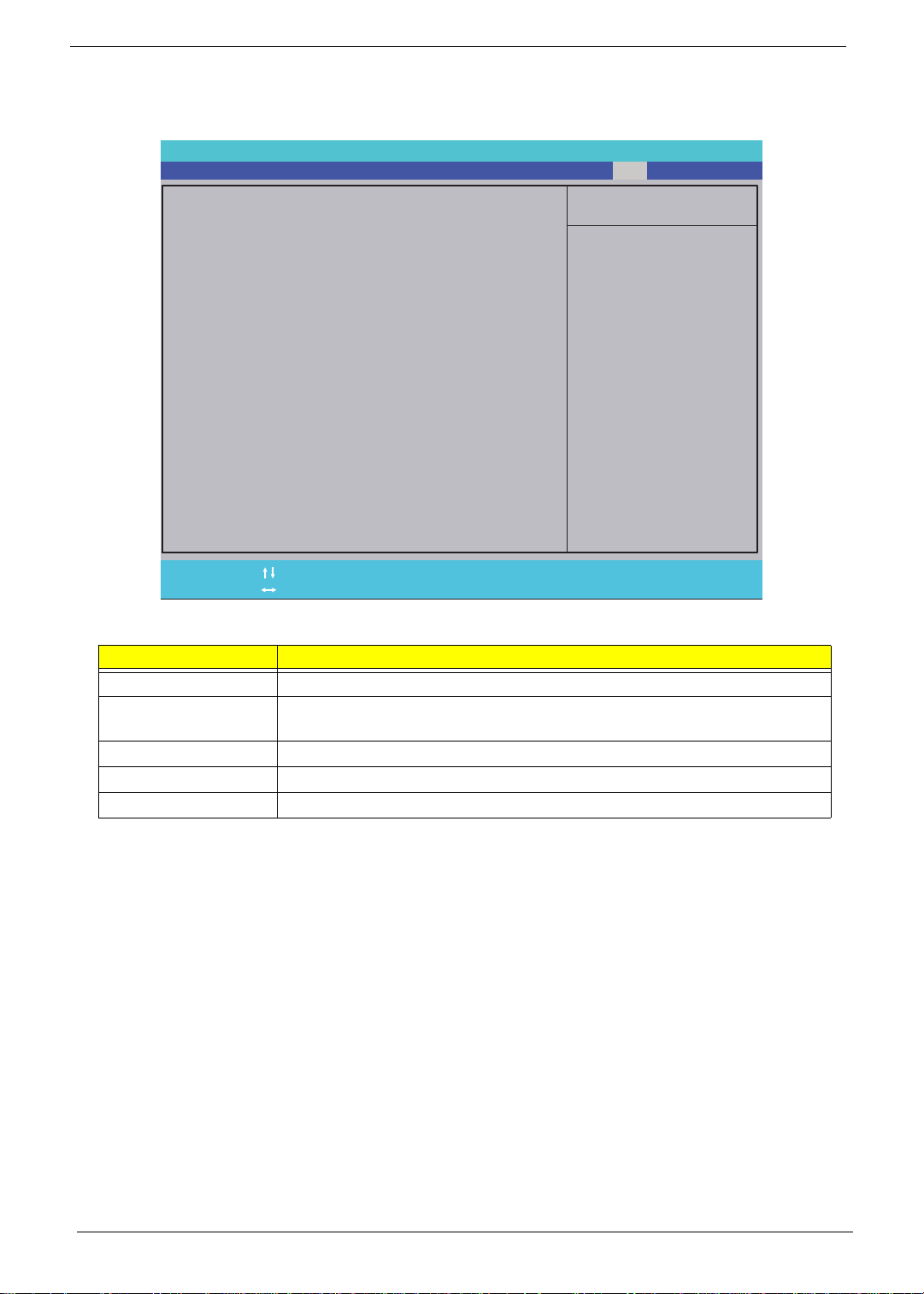
SATA Port 1
The SATA Port 1 screen allows the user to view and adjust SATA settings on Port 1.
PhoenixBIOS Setup Utility
Main Boot
SATA Port 1 [320GB SATA1]
SecurityInfo Advanced
PC Health
Power
Exit
Item Specific Help
Type:
[Auto]
User = you enter
Multi-Sector Transfers:
Multi-Sector Transfers:
LBA Mode Control:
LBA Mode Control:
32 BIT Data Transfer:
32 BIT Data Transfer:
S.M.A.R.T.:
S.M.A.R.T.:
[16 Sectors]
[16 Sectors]
[Enabled]
[Enabled]
[Disabled]
Auto
Auto
parameters of hard-disk
drive installed at this
connection.
Auto = autotypes
hard-disk drive
installed here.
CD-ROM = a CD-ROM drive
is installed here.
ATAPI Removable =
removable disk drive is
installed here.
Help
F1
Exit
Esc
NOTE: The screen above is for your reference only. Actual values may differ.
The table below describes the parameters in this screen. Settings in boldface are the default parameter
settingsT
Parameter Description Format/Option
Type The system automatically detects SATA type. N/A
Multi Sector
Transfers
LBA Mode Control The system enables LBA Mode Control by default. N/A
32Bit Data Transfer Allows the system 32-bit access to maximize the IDE
S.M.A.R.T. The system automatically monitors hard disks for
Select Item
Select Menu
Allows the system IDE controller to transfer multiple
sectors per interuppt.
hard disk data transfer rate.
indicators of reliability in order to anticipate failures.
-/+
Press Enter Press EnterF9F10
Change Values
Setup Defaults
Save and Exit
N/A
Option: Disabled or
Enabled
N/A
20 Chapter 2
Page 31
SATA Port 2
The SATA Port 2 screen allows the user to view and adjust SATA settings on Port 2.
PhoenixBIOS Setup Utility
Main Boot
SATA Port 4 [None]
SecurityInfo Advanced
PC Health
Power
Exit
Item Specific Help
Type:
[Auto]
User = you enter
Multi-Sector Transfers:
Multi-Sector Transfers:
LBA Mode Control:
LBA Mode Control:
32 BIT Data Transfer:
32 BIT Data Transfer:
S.M.A.R.T.:
S.M.A.R.T.:
[Disabled]
[Disabled]
[Disabled]
[Disabled]
[Disabled]
Auto
parameters of hard-disk
drive installed at this
connection.
Auto = autotypes
hard-disk drive
installed here.
CD-ROM = a CD-ROM drive
is installed here.
ATAPI Removable =
removable disk drive is
installed here.
Help
F1
Exit
Esc
NOTE: The screen above is for your reference only. Actual values may differ.
The table below describes the parameters in this screen. Settings in boldface are the default parameter
settingsT
Parameter Description Format/Option
Type The system automatically detects SATA type. N/A
Multi Sector
Transfers
LBA Mode Control The system disables LBA Mode Control by default. N/A
32Bit Data Transfer Allows the system 32-bit access to maximize the IDE
S.M.A.R.T. The system automatically monitors hard disks for
Select Item
Select Menu
The system disables Multi Sector Transfers by default. N/A
hard disk data transfer rate.
indicators of reliability in order to anticipate failures.
-/+
Press Enter Press EnterF9F10
Change Values
Setup Defaults
Save and Exit
Option: Disabled or
Enabled
N/A
Chapter 2 21
Page 32

SATA Port 4
The SATA Port 4 screen allows the user to view and adjust SATA settings on Port 4.
PhoenixBIOS Setup Utility
Main Boot
SATA Port 2 [CD-ROM]
SecurityInfo Advanced
PC Health
Power
Exit
Item Specific Help
Type:
[Auto]
This setting enables
Multi-Sector Transfers:
Multi-Sector Transfers:
LBA Mode Control:
LBA Mode Control:
32 BIT Data Transfer:
32 BIT Data Transfer:
[Disabled]
[Disabled]
[Disabled]
[Disabled]
[Disabled]
or disabled 32 bit IDE
data transfers.
Help
F1
Exit
Esc
NOTE: The screen above is for your reference only. Actual values may differ.
The table below describes the parameters in this screen. Settings in boldface are the default parameter
settingsT
Parameter Description Format/Option
Type The system automatically detects SATA type. N/A
Multi Sector
Transfers
LBA Mode Control The system disables LBA Mode Control by default. N/A
32Bit Data Transfer Allows the system 32-bit access to maximize the IDE
Select Item
Select Menu
The system disables Multi Sector Transfers by default. N/A
hard disk data transfer rate.
-/+
Press Enter Press EnterF9F10
Change Values
Setup Defaults
Save and Exit
Option: Disabled or
Enabled
22 Chapter 2
Page 33
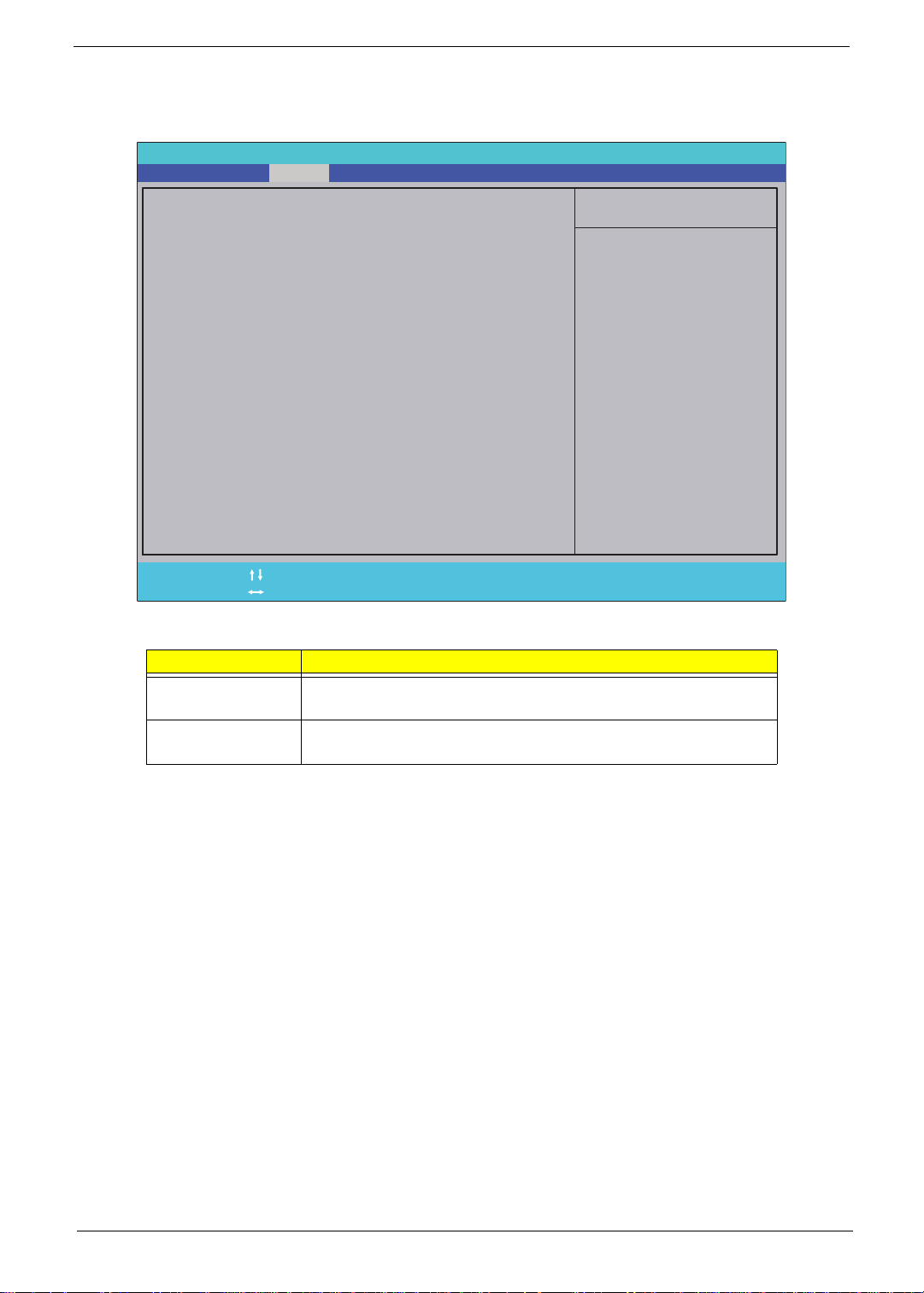
Advanced
The Advanced screen allows the user to configure the various advanced BIOS options.
PhoenixBIOS Setup Utility
Main Boot
X Advanced Chipset Features
X Integrated PeripheralsX Integrated Peripherals
SecurityInfo Advanced PC Health Power
Item Specific Help
Exit
Help
F1
Exit
Esc
The table below describes the items, menus, and submenus in this screen.
Parameter Description
Advanced Chipset
Features
Integrated
Peripherals
Select Item
Select Menu
Enter the Advanced Chipset Features submenu.
Enter the Integrated Peripherals submenu.
-/+
Press Enter Press Enter
Change Values
Setup Defaults
F9
Save and Exit
F10
Chapter 2 23
Page 34
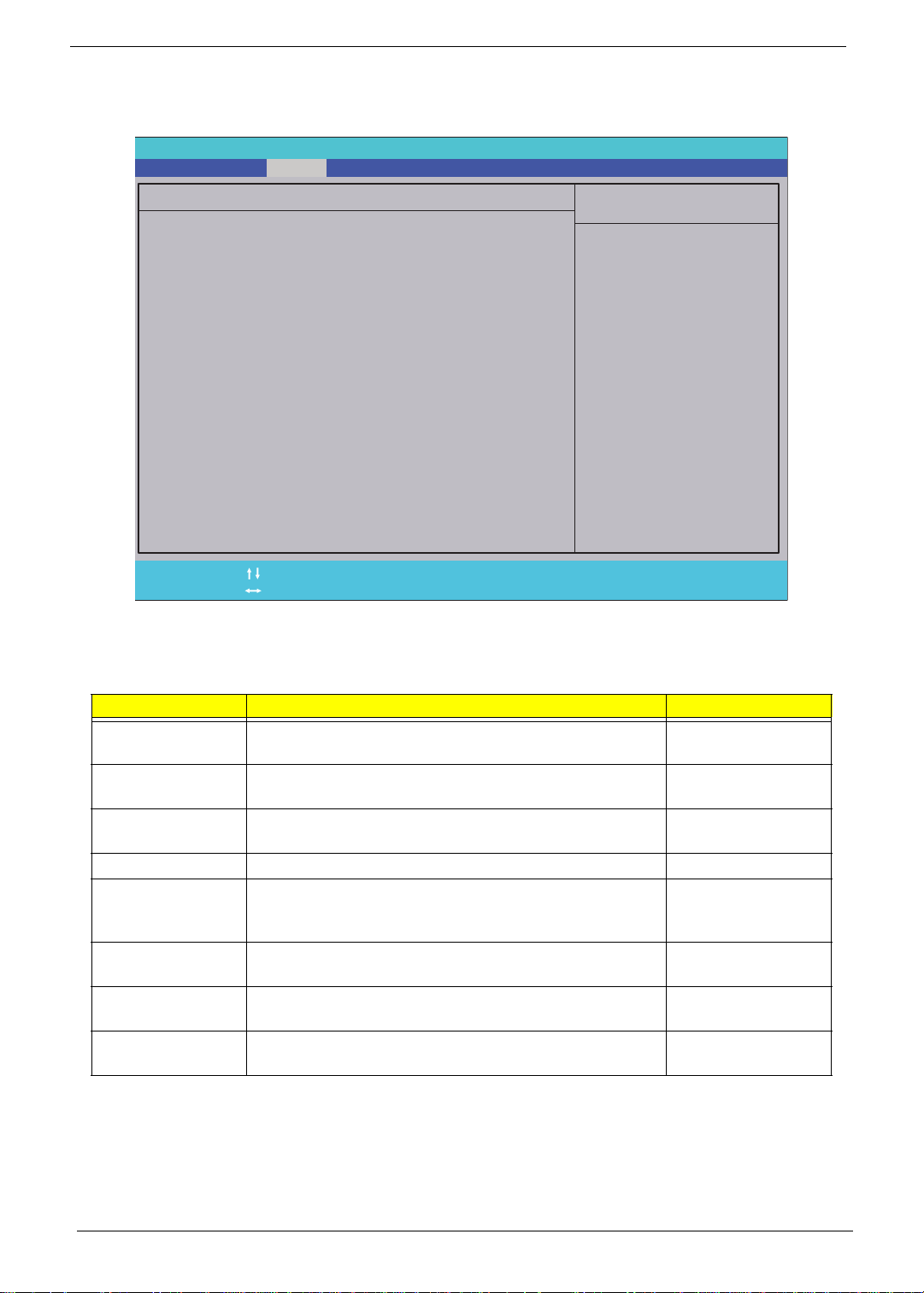
Advanced Chipset Features
The Advanced Chipset screen allows the user to configure chipset settings.
PhoenixBIOS Setup Utility
Advanced
Advanced Chipset Features
Intel EIST:
Intel EIST:
Intel XD Bit:
Intel XD Bit:
Memory Hole Remapping:
Memory Hole Remapping:
Primary Video:
Primary Video:
DVMT Mode:
DVMT Mode:
Pre-Allocated Memory Size:
Pre-Allocated Memory Size:
ICD - Memory Size:
ICD - Memory Size:
DVMT Graphics Memory:
DVMT Graphics Memory:
Help
F1
Exit
Esc
NOTE: The screen above is for your reference only. Actual values may differ.
The table below describes the parameters in this screen. Settings in boldface are the default parameter
settings
Select Item
Select Menu
-/+
Press Enter Press Enter
[Enabled]
[Enabled]
[Enabled]
[Onboard Graphics]
[DVMT]
[32MB]
[128MB]
96MB
Change Values
Item Specific Help
Enable the CPU EIST
Setup Defaults
F9
Save and Exit
F10
Parameter Description Format/Option
Intel EIST Turns on/off Enhanced Intel SpeedStep® Technology
(EIST).
Intel XD Bit: Allows the system to distinguish between bits of code that
may pose a threat to the system.
Memory Hole
Remapping:
Primary Video: This field displays the primary video source. N/A
DVMT Mode: Dynamically allocates system memory for use as video
Pre-Allocated
Memory Size:
ICD - Memory
Size:
DVMT Graphics
Memory
Allows the system to use 4GB of RAM instead of 3GB on
a 64-bit OS and processor.
memory to ensure the most efficient use of available
resources for maximum 2D/3D graphics performance.
This field allows the user to pre-allocate DVMT memory
size.
This field allows the user to allocate ICD memory size. Option: 128MB/
This field displays the size of DVMT Graphics Memory. N/A
Option: Disabled or
Enabled
Option: Disabled or
Enabled
Option: Disabled or
Enabled
N/A
Option: 32MB/
64MB/128MB
256MB/MaxDVMT
24 Chapter 2
Page 35
Integrated Peripherals
The Integrated Peripherals screen allows the user to configure various display settings.
PhoenixBIOS Setup Utility
Advanced
Integrated Peripherals
Onboard SATA Controller:
Onboard SATA Controller:
SATA Controller Mode:
SATA Controller Mode:
Legacy USB Support:
Legacy USB Support:
Onboard Audio Controller:
Onboard Audio Controller:
Onboard LAN Controller:
Onboard LAN Controller:
Onboard LAN Option ROM:
Onboard LAN Option ROM:
Help
F1
Exit
Esc
NOTE: The screen above is for your reference only. Actual values may differ.
The table below describes the parameters in this screen. Settings in boldface are the default parameter
settings
Select Item
Select Menu
-/+
Press Enter Press Enter
[Enabled]
[AHCI]
[Enabled]
[Auto]
[Enabled]
[Disabled]
Change Values
Item Specific Help
Enable the SATA
Setup Defaults
F9
Save and Exit
F10
Parameter Description Format/Option
Onboard SATA
Controller
SATA Controller
Mode
Legacy USB
Support
Onboard Audio
Controller
Onboard LAN
Controller
Onboard LAN
Option ROM
This field allows the user to enable or disable the Onboard
SATA Controller.
This field allows the user to select the SATA operation
mode.
This field allows the user to enable or disable BIOS
itneration with a USB keyboard.
This field allows the user to enable or disable the Onboard
Audio Controller.
This field allows the user to enable or disable the Onboard
LAN Controller.
This field allows the user to enable or disable the Onboard
LAN Option ROM.
Option: Disabled or
Enabled
Option: Enhanced or
AHCI
Option: Disabled or
Enabled
Option: Disabled or
Auto
Option: Disabled or
Enabled
Option: Disabled or
Enabled
Chapter 2 25
Page 36
Security
The Security screen contains parameters that help safeguard and protect your computer from unauthorized
use.
PhoenixBIOS Setup Utility
Main Boot
Supervisor Password Is:
Supervisor Password Is:
User Password Is:
User Password Is:
Change Supervisor Password:
Change Supervisor Password:
Change User Password:
Change User Password:
Security Option:
SecurityInfo Advanced
Installed
Installed
Not Installed
Not Installed
[Press Enter]
[Press Enter]
[Press Enter]
[Press Enter]
[Setup]
[Setup]
PowerPC Health
Exit
Item Specific Help
Enables password entry
Enables password entry
on boot.
on boot.
Help
F1
Exit
Esc
The table below describes the parameters in this screen. Settings in boldface are the default and suggested
parameter settings.
Parameter Description Format/Option
Supervisor Password Is Shows the setting of the Supervisor password Option: Not
User Password Is Shows the setting of the User password Option: Not
Change Supervisor
Password
Change User Password Press Enter to set the user password. N/A
Security Option Select the desired level of security protection covered
NOTE: When you are prompted to enter a password, you have three tries before the system halts. Don’t forget
your password. If you forget your password, you may have to return your computer to your dealer to
reset it.
Select Item
Select Menu
Press Enter to set the supervisor password. When
set, this password protects the BIOS Setup Utility
from unauthorized access. The user can not either
enter the Setup menu nor change the value of
parameters.
by the Supervisor password. Setup enables
password security for the BIOS Setup Utility and
System enables password security every time the
device boots.
-/+
Press Enter Press Enter
Change Values
Setup Defaults
F9
Save and Exit
F10
Installed or
Installed
Installed or
Installed
N/A
Setup or System
26 Chapter 2
Page 37
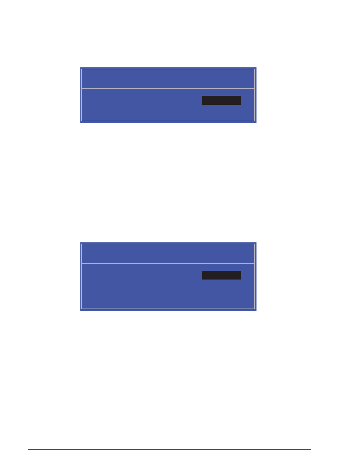
Setting a Password
Follow these steps as you set the user or the supervisor password:
1. Use the ↑ and ↓ keys to highlight the Set Supervisor Password parameter and press the Enter key. The
Set Supervisor Password box appears:
Set Supervisor Password
Enter New Password [ ][ ]
Confirm New Password [ ]
2. Type a password in the “Enter New Password” field. The password length can not exceeds 8
alphanumeric characters (A-Z, a-z, 0-9, not case sensitive). Retype the password in the “Confirm New
Password” field.
IMPORTANT:Be very careful when typing your password because the characters do not appear on the screen.
3. Press Enter. After setting the password, the computer sets the User Password parameter to “Set”.
4. If desired, you can opt to enable the Password on boot parameter.
5. When you are done, press F10 to save the changes and exit the BIOS Setup Utility.
Removing a Password
Follow these steps:
1. Use the ↑ and ↓ keys to highlight the Set Supervisor Password parameter and press the Enter key. The
Set Password box appears:
Set Supervisor Password
Enter Current Password [ ][ ]
Enter New Password [ ]
Confirm New Password [ ][ ]
2. Type the current password in the Enter Current Passwor d fi el d an d press Enter.
3. Press Enter twice without typing anything in the Enter New Password and Confirm New Password fields.
The computer then sets the Supervisor Password parameter to “Clear”.
4. When you have changed the settings, press u to save the changes and exit the BIOS Setup Utility.
Chapter 2 27
Page 38

Changing a Password
1. Use the ↑ and ↓ keys to highlight the Set Supervisor Password parameter and press the Enter key. The
Set Password box appears.
Set Supervisor Password
Enter Current Password [ ][ ]
Enter New Password [ ]
Confirm New Password [ ][ ]
2. Type the current password in the Enter Current Passwor d fi el d an d press Enter.
3. Type a password in the Enter New Password field. Retype the password in the Confirm New Password
field.
4. Press Enter. After setting the password, the computer sets the User Password parameter to “Set”.
5. If desired, you can enable the Password on boot parameter.
6. When you are done, press F10 to save the changes and exit the BIOS Setup Utility.
If the verification is OK, the screen will display as following.
Setup Notice
Changes have been saved.
[Continue][Continue]
The password setting is complete after the user presses Enter.
If the current password entered does not match the actual current password, the screen will show you the
Setup Warning.
Setup Warning
Invalid Password.
[Continue][Continue]
If the new password and confirm new password strings do not match, the screen will display the following
message.
Setup Warning
Passwords do not match.
Re-enter password.
[Continue][Continue]
28 Chapter 2
Page 39
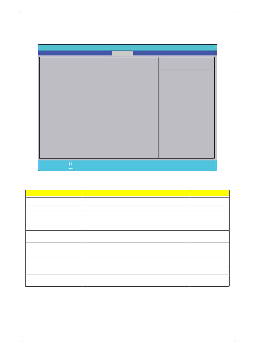
PC Health
The PC Health screen displays CPU/Chipset temperature information and contains customiza ble safety
monitors for the CPU.
PhoenixBIOS Setup Utility
Main Boot
CPU Temperature:
CPU Temperature:
CPU Fan Speed:
CPU Fan Speed:
CPU Core:
CPU Core:
+1.1V
+1.1V
+3.30V
+3.30V
+5.00V
+5.00V
+12.0V
+12.0V
Memory +1.50V
Memory +1.50V
Shutdown Temperature:
Shutdown Temperature:
SecurityInfo Advanced Power
=
=
=
=
=
=
PC Health
40 °C
40 °C
0 RPM
0 RPM
1.26V
1.26V
1.11V
1.11V
3.32V
3.32V
4.90V
4.90V
12.09V
12.09V
1.55V
1.55V
[Disabled]
Exit
Item Specific Help
Shutdown Temperature
Help
F1
Exit
Esc
The table below describes the parameters in this screen. Settings in boldface are the default and suggested
parameter settings.
Parameter Description Option
CPU Temperature This field displays the current CPU temperature (°C). N/A
CPU Fan Speed This field displays the current CPU Fan Speed (RPM). N/A
CPU Core This field displays the current CPU Core. N/A
+1.1V This field displays measured voltage at the nominal
+3.30V This field displays measured voltage at the nominal
+5.00V This field displays measured voltage at the nominal
+12.0V This field displays measured voltage at the nominal
Memory +1.50V This field displays the memory voltage. N/A
Shutdown Temperature This field allows the user to enable or disable CPU
Select Item
Select Menu
1.1V bus.
3.30V bus.
5.00V bus.
12.0V bus.
shutdown at a certain temperature.
-/+
Press Enter Press Enter
Change Values
Setup Defaults
F9
Save and Exit
F10
N/A
N/A
N/A
N/A
Option: Enabled
or Disabled
Chapter 2 29
Page 40
Power
The Power screen contains parameters used for device power management.
PhoenixBIOS Setup Utility
Main Boot
ACPI Suspend Mode:
ACPI Suspend Mode:
SecurityInfo Advanced
[S3 (STR)]
PowerPC Health
Exit
Item Specific Help
Power On by RTC Alarm:
Power On by RTC Alarm:
[Disabled]
Enter one of the ACPI
states.
Power On by Onboard LAN:
Power On by Onboard LAN:
Wake Up by USB KB/Mouse:
Wake Up by USB KB/Mouse:
Restore On AC Power Loss:
Restore On AC Power Loss:
Help
F1
Exit
Esc
The table below describes the parameters in this screen. Settings in boldface are the default and suggested
parameter settings.
Parameter Description Option
ACPI Suspend Mode This field allows the user to set the ACPI Suspend
Power On by RTC Alarm This field allows the user to disable or enable auto
Power On by Onboard
LAN
Wake Up by USB KB/
Mouse
Restore On AC Power
Loss
Select Item
Select Menu
Mode.
wake up at a fixed time everyday.
This field allows the user to disable or enable wake up
when the system power is off and a LAN device is
activated.
This field allows the user to disable or enable wake up
when the system is in standby and a USB device is
activated.
Set the state the device returns to in the event of AC
power loss. Off causes the device to remain off in the
event of power loss and On restarts the device when
AC power resumes.
[Disabled]
[Enabled]
[Last State]
-/+
Change Values
Press Enter Press Enter
Setup Defaults
F9
Save and Exit
F10
Option:
S1(POS)/S3
(STR)
Option: Disabled
or Enabled
Option: Disabled
or Enabled
Option: Enabled
or Disabled
Option: On/Off/
Last State
30 Chapter 2
Page 41
Boot
This menu allows the user to decide the order of boot devices to load the operating system. Bootable devices
includes the USB diskette drives, the onboard hard disk drive and the DVD drive.
PhoenixBIOS Setup Utility
Main Boot
Boot priority order:
Boot priority order:
1: Internal SSD:
1: Internal SSD:
2: Internal HDD: ST3320418AS-(S1)
2: Internal HDD: ST3320418AS-(S1)
3: SATA ODD: Optiarc DVD RW AD-7643S-(S
3: SATA ODD: Optiarc DVD RW AD-7643S-(S
4: PCI BEV:
4: PCI BEV:
5: USB HDD:
5: USB HDD:
6: USB KEY:
6: USB KEY:
7:
7:
8:
8:
Excluded from boot order:
Excluded from boot order:
1: USB FDC:
1: USB FDC:
1: USB CDROM:
1: USB CDROM:
SecurityInfo Advanced PowerPC Health
Exit
Item Specific Help
Keys used to view or
configure devices:
Up and Down arrows
select a device.
<+> and <-> moves
the device up or down.
<f> and <r> specifies
the device fixed or
removable.
<x> exclude or include
the device to boot.
<Shift + 1> enables or
disables a device.
<1 - 4>Loads default
boot sequence.
F1
Esc
Help
Exit
Select Item
Select Menu
-/+
Press Enter Press Enter
Change Values
Setup Defaults
F9
Save and Exit
F10
Chapter 2 31
Page 42
Exit
The Exit screen allows you to save or discard any changes you made and quit the BIOS Utility.
PhoenixBIOS Setup Utility
Main Boot
Exit Saving Changes
Exit Saving Changes
Exit Discarding Changes
Exit Discarding Changes
Load Setup Defaults
Load Setup Defaults
Discard Changes
Discard Changes
Save Changes
Save Changes
SecurityInfo Advanced PowerPC Health
Exit
Item Specific Help
Exit System Setup and
save your changes to
CMOS.
Help
F1
Exit
Esc
The table below describes the parameters in this screen.
Parameter Description
Exit Saving Changes Exit System Setup and save your changes to CMOS.
Exit Discarding
Changes
Load Setup Default Load default values for all SETUP item.
Discard Changes Load previous values from CMOS for all SETUP items.
Save Changes Save Setup Data to CMOS.
Select Item
Select Menu
Exit utility without saving setup data to CMOS.
-/+
Press Enter Press Enter
Change Values
Setup Defaults
F9
Save and Exit
F10
32 Chapter 2
Page 43
Chapter 3
Machine Disassembly and Replacement
IMPORTANT:The outside housing and color may vary from the mass produced model.
This chapter contains step-by-step procedures on how to disassemble the computer for maintenance and
troubleshooting.
Disassembly Requirements
To disassemble the computer, you need the following tools:
• Wrist grounding strap and conductive mat for preventing electrostatic discharge
• Flat screwdriver
• Philips screwdriver
NOTE: The screws for the different components vary in size. During the disassembly process, group the
screws with the corresponding components to avoid mismatch when putting back the components.
General Information
Pre-disassembly Instructions
Before proceeding with the disassembly procedure, make sure that you do the following:
1. Turn off the power to the system and all peripherals.
2. Unplug the AC adapter and all power and signal cables from th e system.
3. Place the system on a flat, stable surface.
The flowchart provided in the succeeding disassembly section illustrates the entire disassembly sequence.
Observe the order of the sequence to avoid damage to any of the hardware components.
Main Screw List
Screw Quantity Part Number
M3.0*5.0-B
M3.0*6.0-C
M3.0*10-P
M3.0*15-P
M2.5*5.0-I
M2.0*3.0-I
6-32UNC*5-B
Chapter 3 33
Page 44

Disassembly Process
Disassembly Flowchart
Turn off power and
disconnect all
cables before
proceeding
Remove
Hinge Cover
Remove
Rear Covers
Remove
HDD Module
Remove
Hinge
Remove
Home Button
Board
Remove
RAM Cover
Remove
Back Cover
Remove
RAM
Remove
B-CAS Board
Remove
Inverter Board
Remove
Control Board
Remove
Back Frame
Remove
WLAN Board
Remove
Thermal Module
Remove
Mainboard
Cables
Remove
Mainboard
Remove
Power Supply
Remove
Card Reader
Board
Remove
Audio Board
Remove
Web Camera
Board
Remove
ODD Button
Board
Remove
ODD Module
Remove
SSD
Remove
TV Tuner Board
Remove
Fan
Remove
CPU
Remove
LCD Assembly
Remove
LCD Panel
34 Chapter 3
Page 45
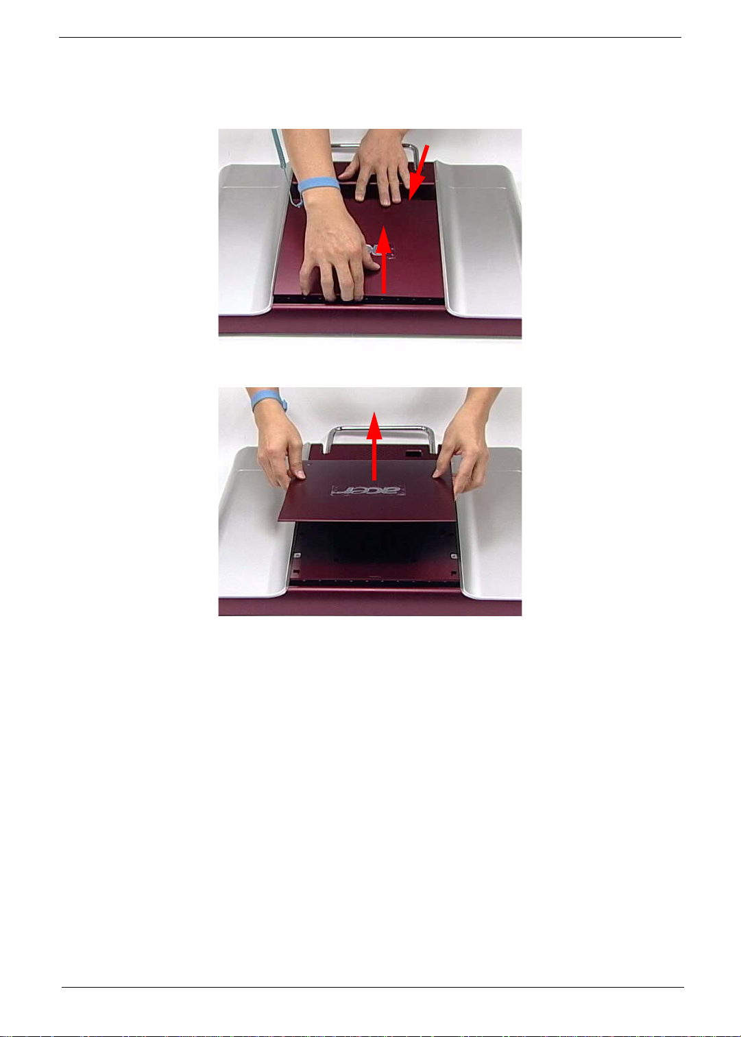
Removing the RAM Cover
1. See “Pre-disassembly Instructions” on page 33.
2. Apply pressure to one end of the RAM Cove r, while pulling up with the opposite hand as shown.
3. Lift the RAM Cover clear of the device.
Chapter 3 35
Page 46
Removing the Hinge Cover
1. See “Removing the RAM Cover” on page 35.
2. Grasp the Hinge Cover with both hands.
3. Lift the Hinge Cover clear of the device.
36 Chapter 3
Page 47
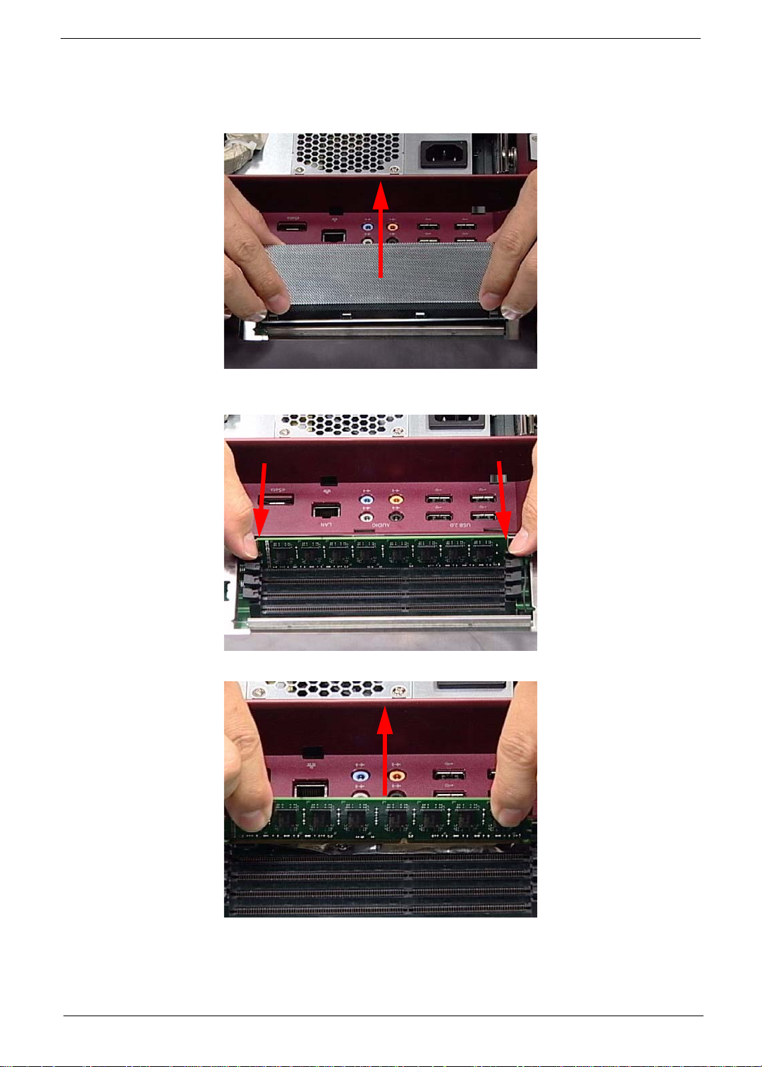
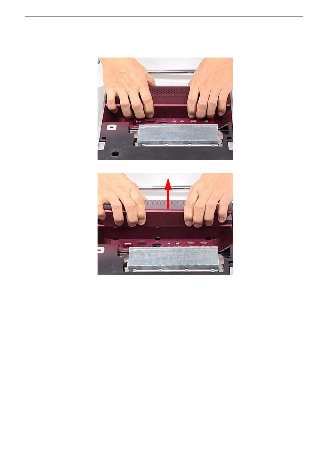
Removing the RAM
1. See “Removing the Hinge Cover” on page 36.
2. Lift the RAM Shielding clear of the device.
3. Unlock the latches on either side of the RAM by pressing down as shown. There is an audible click when the
latch is unlocked.
4. Lift each RAM module from its slot.
Chapter 3 37
Page 48
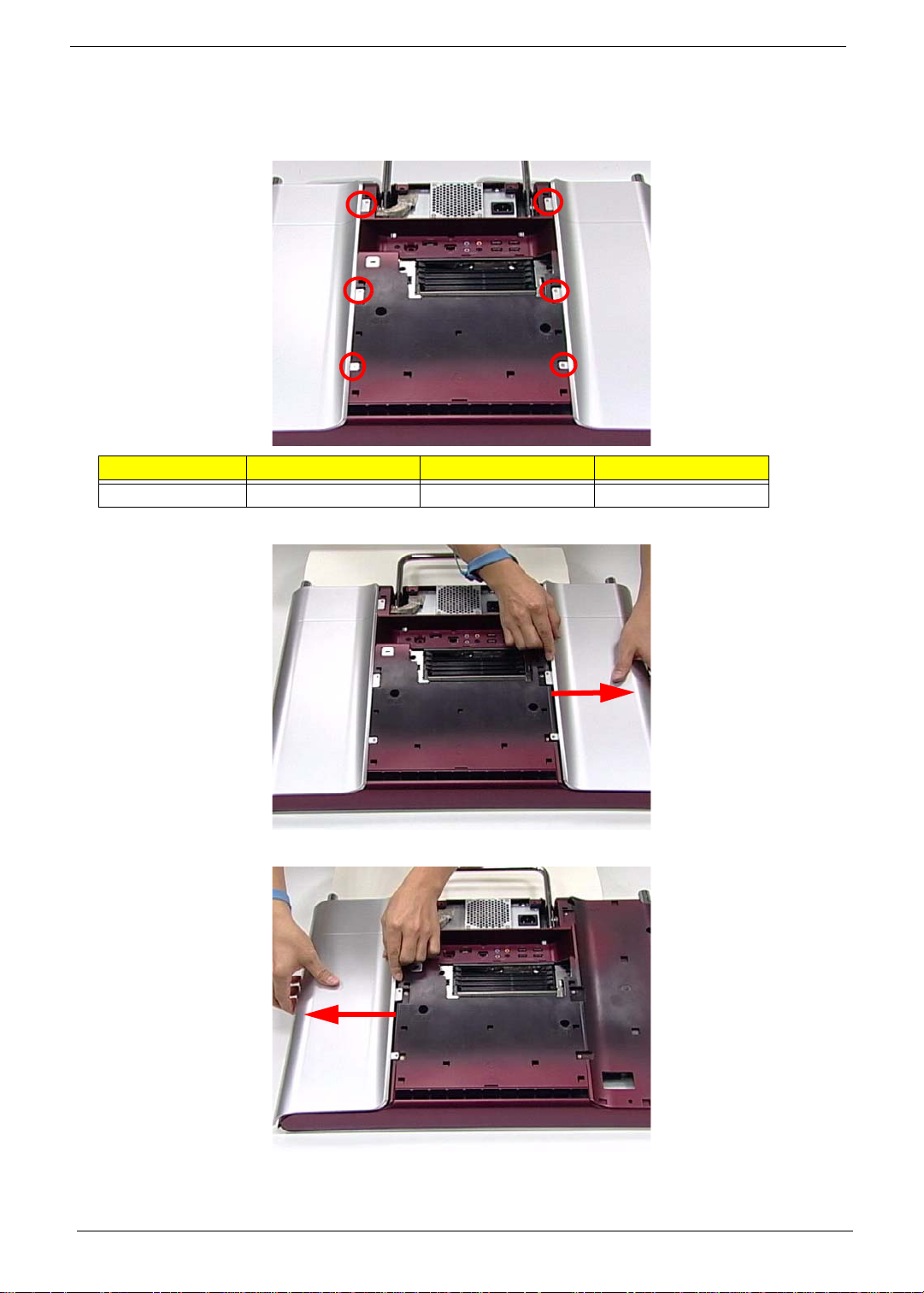
Removing the Rear Covers
1. See “Removing the RAM” on page 37.
2. Remove the six (6) screws that secure the Rear Covers.
Step Size Quantity Screw Type
Rear Covers 6
3. Use both hands to gently push the rear cover outward from the device as shown.
4. Repeat the previous step for the remaining rear cover.
38 Chapter 3
Page 49
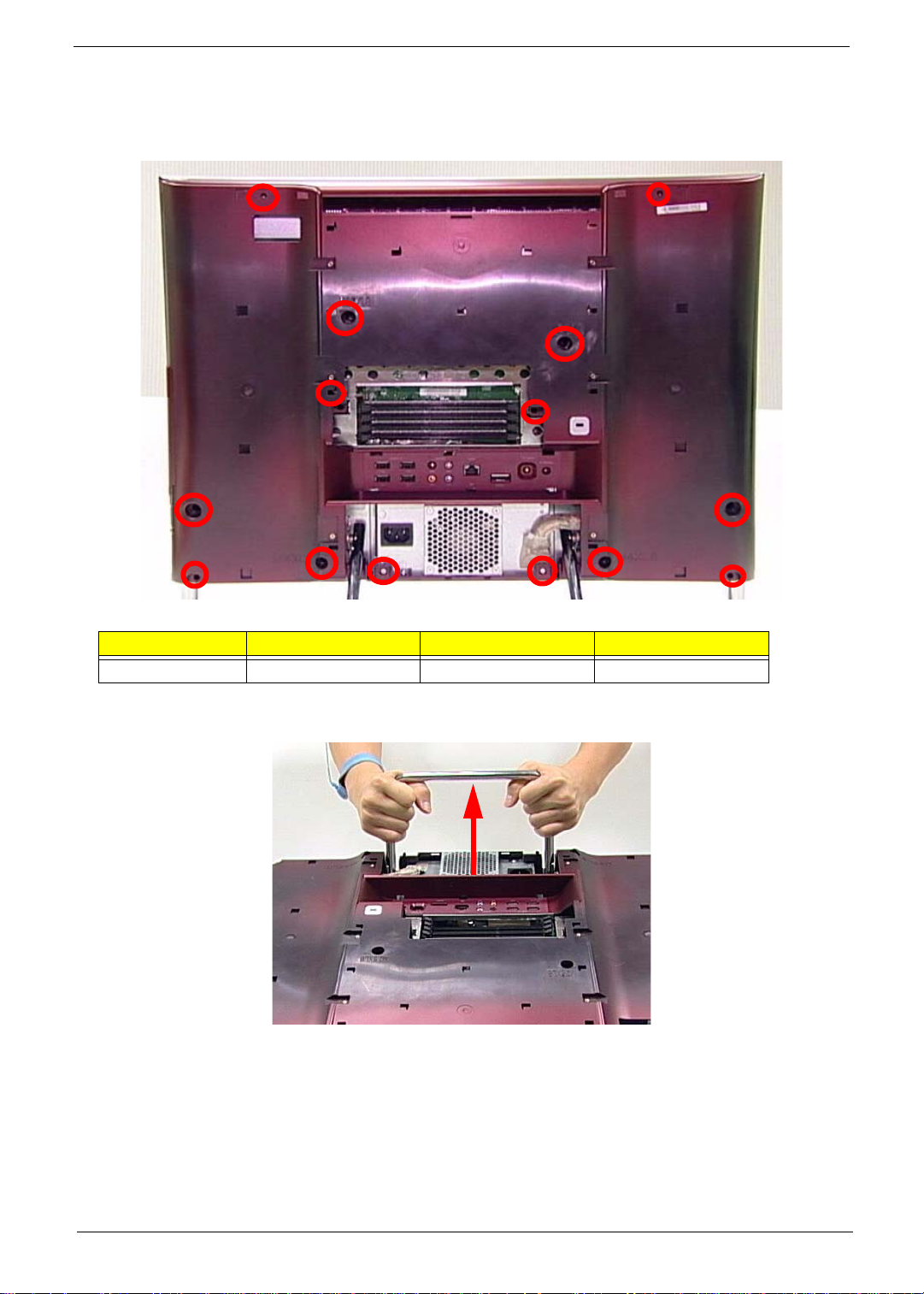
Removing the Back Cover
1. See “Removing the Rear Covers” on page 38.
2. Remove the fourteen (14) screws securing the Back Cover.
Step Size Quantity Screw Type
Back Cover 14
3. Use both hands to move the Hinge up into the stand position. There is an audible click when the Hinge is
locked in position.
NOTE: In order to lift the Back Cover away, the Hinge must be in the stand position.
Chapter 3 39
Page 50
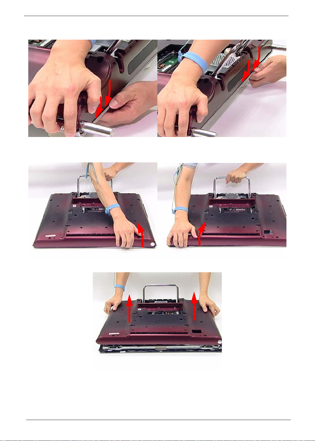
4. Place one hand firmly on the Back Cover. Use the opposite hand to pry the Bezel away, working from one
corner to the other as shown. Repeat this step until all guides along the bottom of the device are unlocked.
5. Place one hand firmly on the Hinge. Use the opposite hand to pull the top of the Back Cover away from the
Bezel, working from one corner to the other as shown. Repeat this step until all guides along the top of the
device are unlocked.
6. Lift the Back Cover clear of the device.
40 Chapter 3
Page 51

Removing the Hinge
1. See “Removing the Back Cover” on page 39.
2. Replace the Hinge to the carry position.
3. Remove the six (6) screws securing the Hinge.
Step Size Quantity Screw Type
Hinge 6
4. Lift the Hinge clear of the device.
Chapter 3 41
Page 52

Removing the Back Frame
1. See “Removing the Hinge” on page 41.
2. Unstick the EMI Cable Mylar as shown.
CAUTION: Do not remove the EMI Cable completely; the cable is still attached to the device.
3. Disconnect the CPU Power Cable (A), the SATA Power Cable (B), and the HDD Power Cable (C) as shown:
A
c
B
42 Chapter 3
Page 53
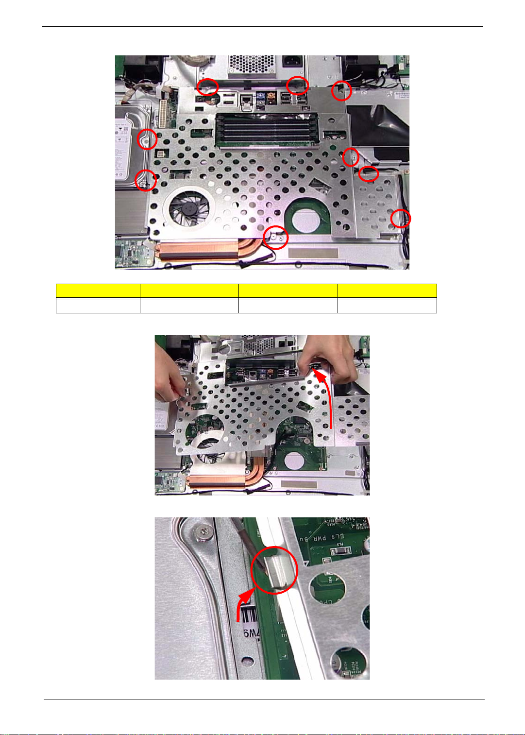
4. Remove the nine (9) screws securing the Back Frame.
Step Size Quantity Screw Type
Back Frame 9
5. Lift one end of the Back Frame as shown.
6. Carefully unhook the guide at the opposite end before lifting away completely.
Chapter 3 43
Page 54
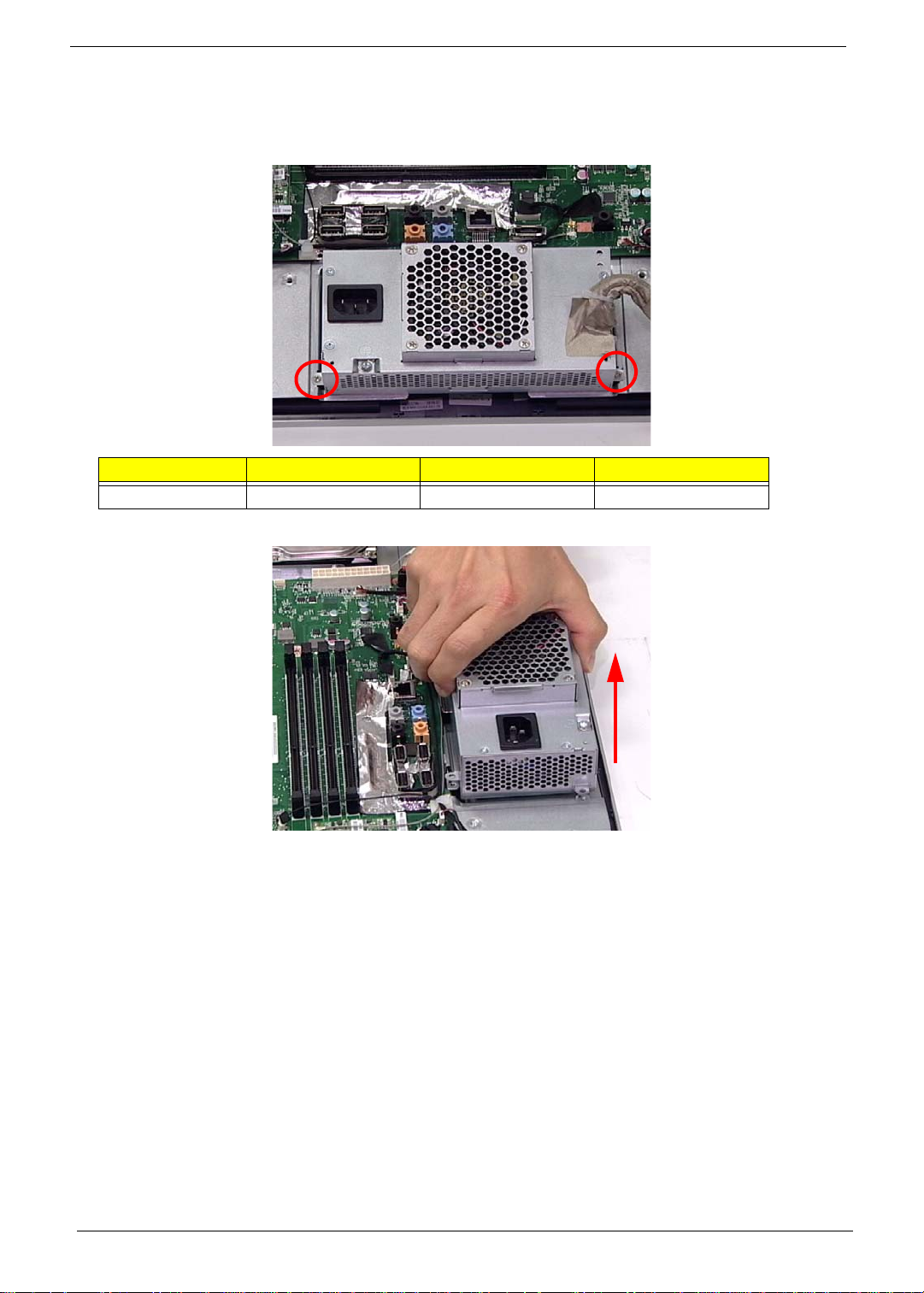
Removing the Power Supply
1. See “Removing the Back Frame” on page 42.
2. Remove two (2) screws securing the Power Supply as shown.
Step Size Quantity Screw Type
Power Supply 2
3. Lift the Power Supply clear of the device.
44 Chapter 3
Page 55
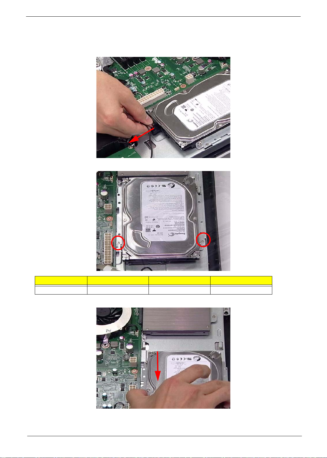
Removing the HDD Module
1. See “Removing the Power Supply” on page 44.
2. Disconnect the HDD Cable as shown.
3. Remove two (2) screws securing the HDD Module.
Step Size Quantity Screw Type
HDD Module 2
4. Slide the HDD Module out of the flanges.
Chapter 3 45
Page 56

Removing the B-CAS Board
1. See “Removing the HDD Module” on page 45.
2. Remove the three (3) screws securing the B-CAS Board.
Step Size Quantity Screw Type
B-CAS 3
3. Lift out the B-CAS Board and turn it over. Disconnect the B-CAS Board Cable underneath.
46 Chapter 3
Page 57
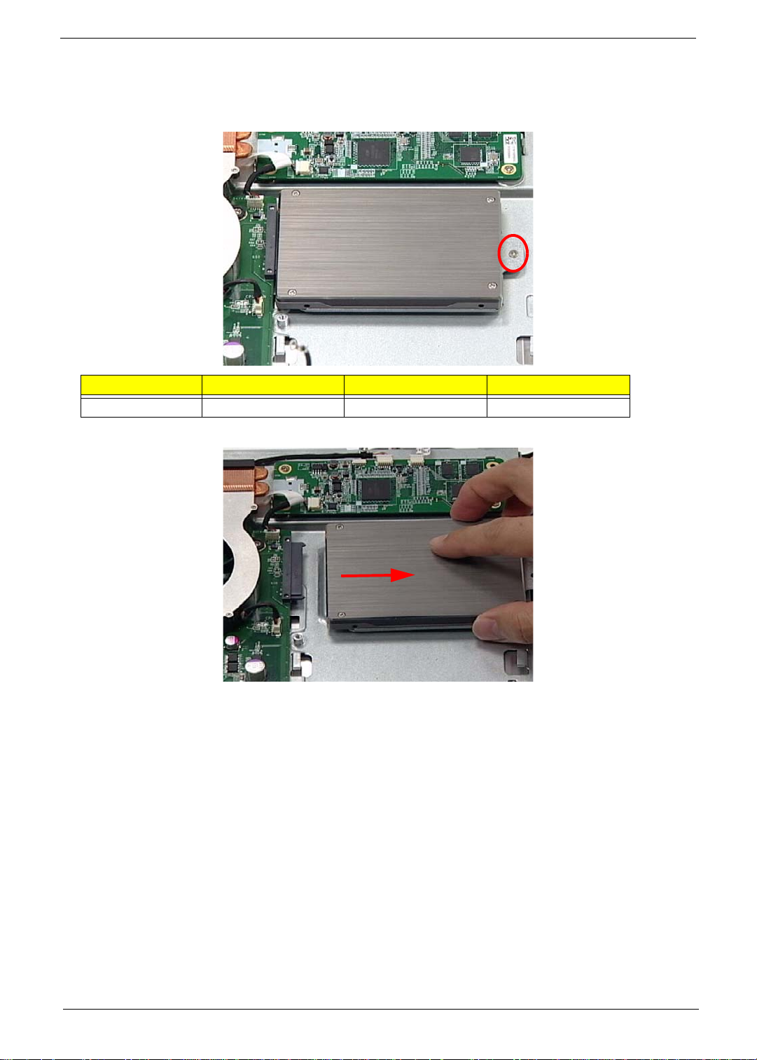
Removing the SSD Module
1. See “Removing the B-CAS Board” on page 46.
2. Remove one (1) screw securing the SSD Module as shown.
Step Size Quantity Screw Type
SSD Module 1
3. Slide the SSD out of the flange.
Chapter 3 47
Page 58
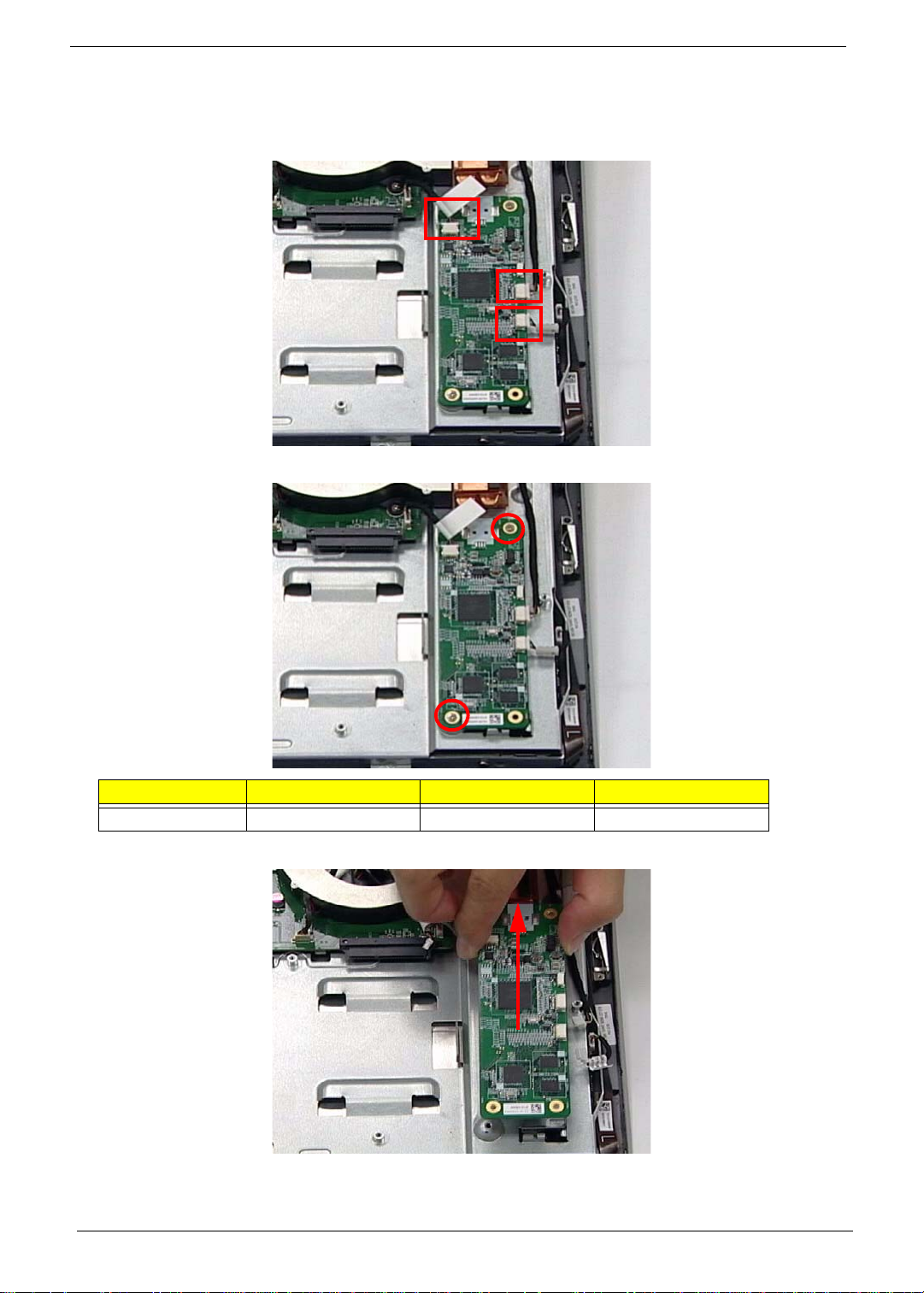
Removing the Control Board
1. See “Removing the SSD Module” on page 47.
2. Disconnect three (3) cables on the Control Board as shown
3. Remove the two (2) screws securing the Control Board as shown.
Step Size Quantity Screw Type
Control Board 2
4. Lift the Control Board clear of the device.
48 Chapter 3
Page 59

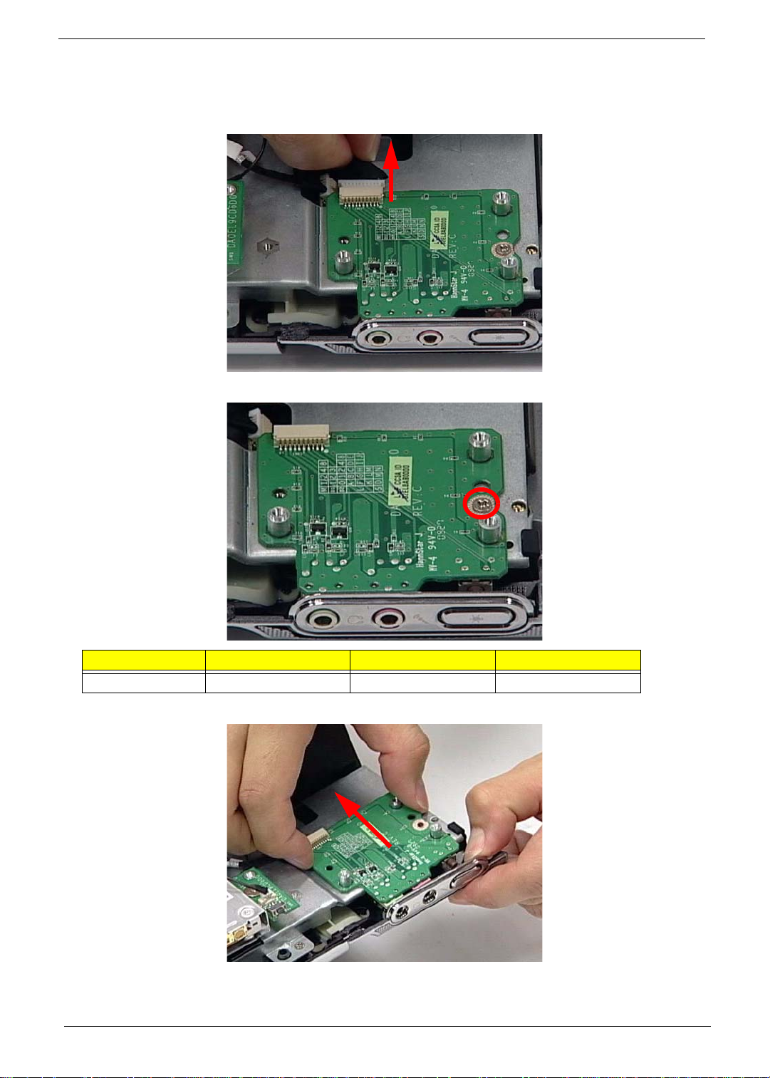
Removing the Card Reader Board
1. See “Removing the Control Board” on page 48.
2. Disconnect the Card Reader Board Cable.
3. Remove three (3) securing screws from the Card Reader Board.
Step Size Quantity Screw Type
Card Reader Board 3
4. Lift the Card Reader Board clear of the device.
Chapter 3 49
Page 60
Removing the Audio Board
1. See “Removing the Card Reader Board” on page 49.
2. Disconnect the Audio Board Cable.
3. Remove one (1) screw from the Audio Board.
Step Size Quantity Screw Type
Audio Board 1
4. Carefully remove the Audio Board by separating it from the bracket and three guide pins as shown.
50 Chapter 3
Page 61
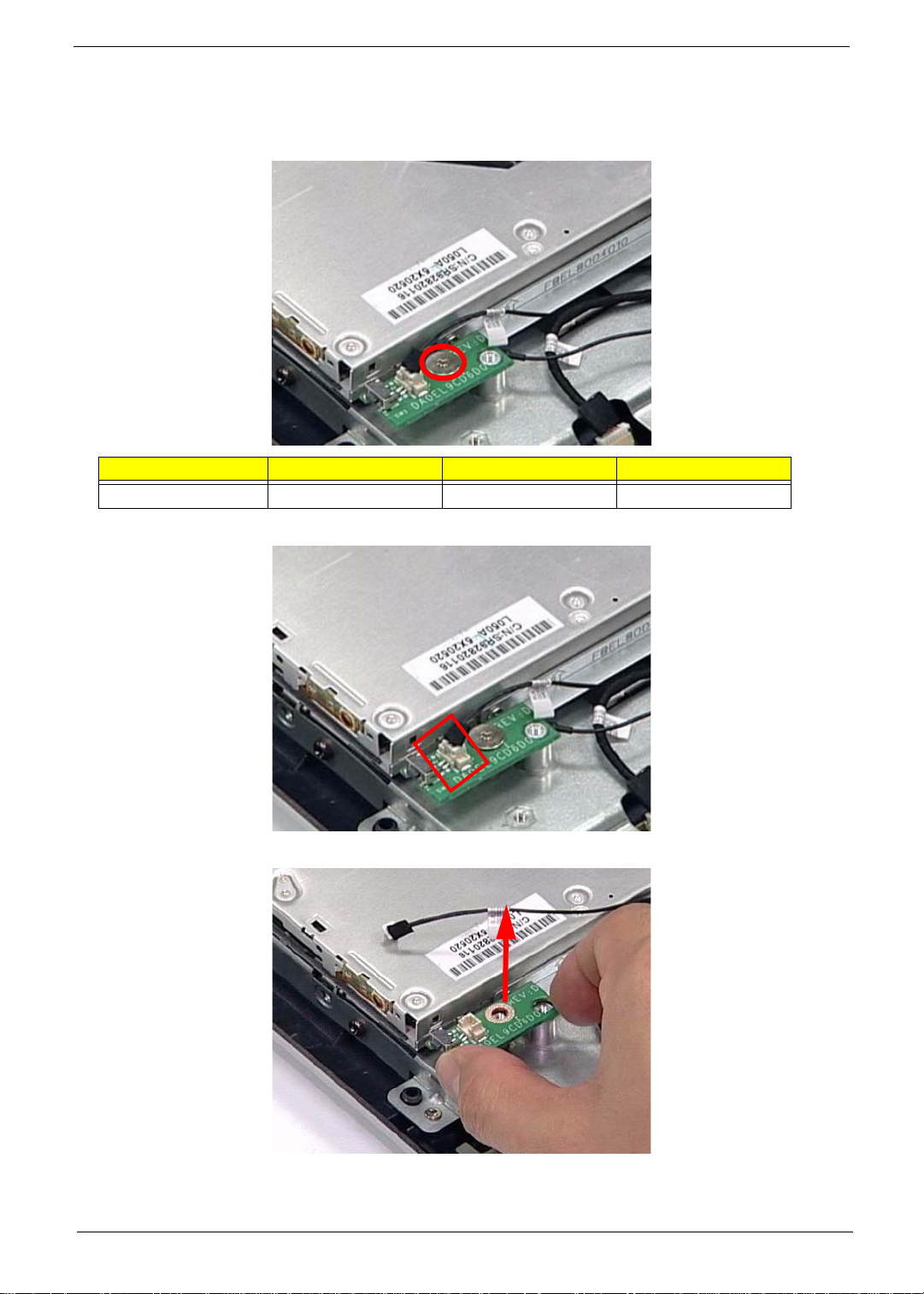
Removing the ODD Button Board
1. See “Removing the Audio Board” on page 50.
2. Remove one (1) securing screw from the ODD Button Board.
Step Size Quantity Screw Type
ODD Button Board 1
3. Disconnect one (1) cable from the ODD Button Board.
4. Lift the ODD Button Board clear of the device.
Chapter 3 51
Page 62
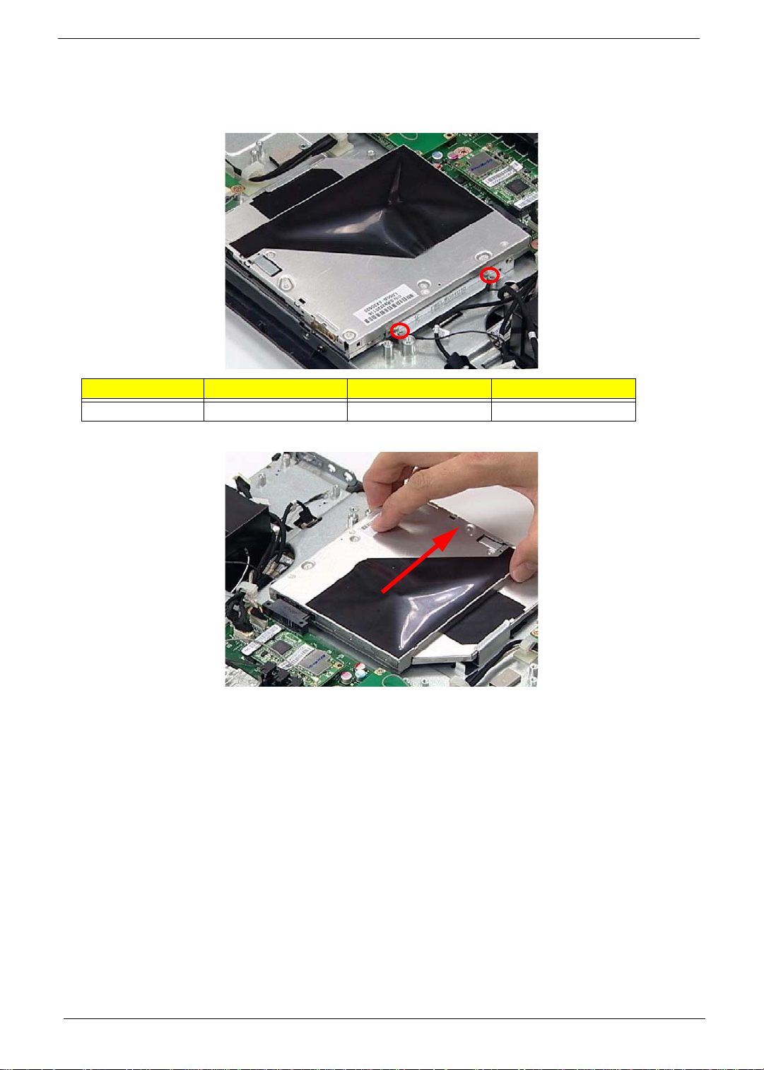
Removing the ODD Module
1. See “Removing the ODD Button Board” on page 51.
2. Remove two (2) securing screws from the ODD Module.
Step Size Quantity Screw Type
ODD Module 2
3. Slide the ODD Module out of the flange.
52 Chapter 3
Page 63
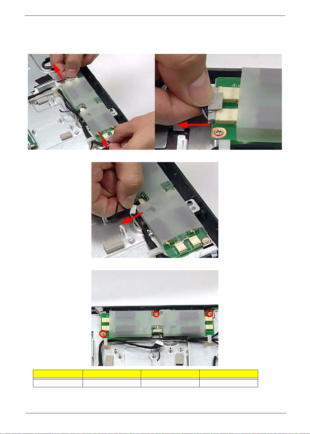
Removing the Inverter Board
1. See “Removing the ODD Module” on page 52.
2. Carefully disconnect both Inverter Cables from either side of the Inverter Board.
3. Disconnect the Mainboard Cable as shown.
4. Remove three (3) securing screws from the Inverter Board.
Step Size Quantity Screw Type
Inverter Board 3
Chapter 3 53
Page 64
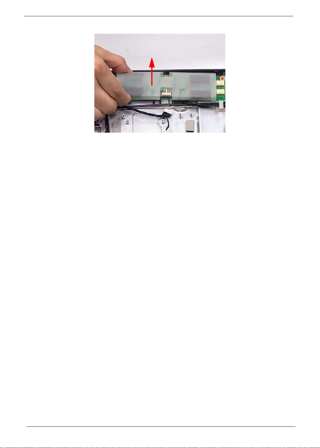
5. Lift the Inverter Board clear of the device.
54 Chapter 3
Page 65

Removing the Home Button Board
1. See “Removing the Inverter Board” on page 53.
2. Remove one (1) securing screw from the Home Button Board.
Step Size Quantity Screw Type
Home Button Board 1
3. Disconnect one (1) cable from the Home Button Board.
4. Lift the Home Button Board away as shown.
Chapter 3 55
Page 66
Removing the Web Camera Board
1. See “Removing the Home Button Board” on page 55.
2. Remove two (2) screws securing the Web Camera Board as shown.
Step Size Quantity Screw Type
Web Camera Board SCREW M2.0*4 2
3. Gently lift out the Web Camera Board and turn it over.
CAUTION: Do not use excessive force when removing the Web Camera Board.
4. Disconnect the cable underneath.
56 Chapter 3
Page 67
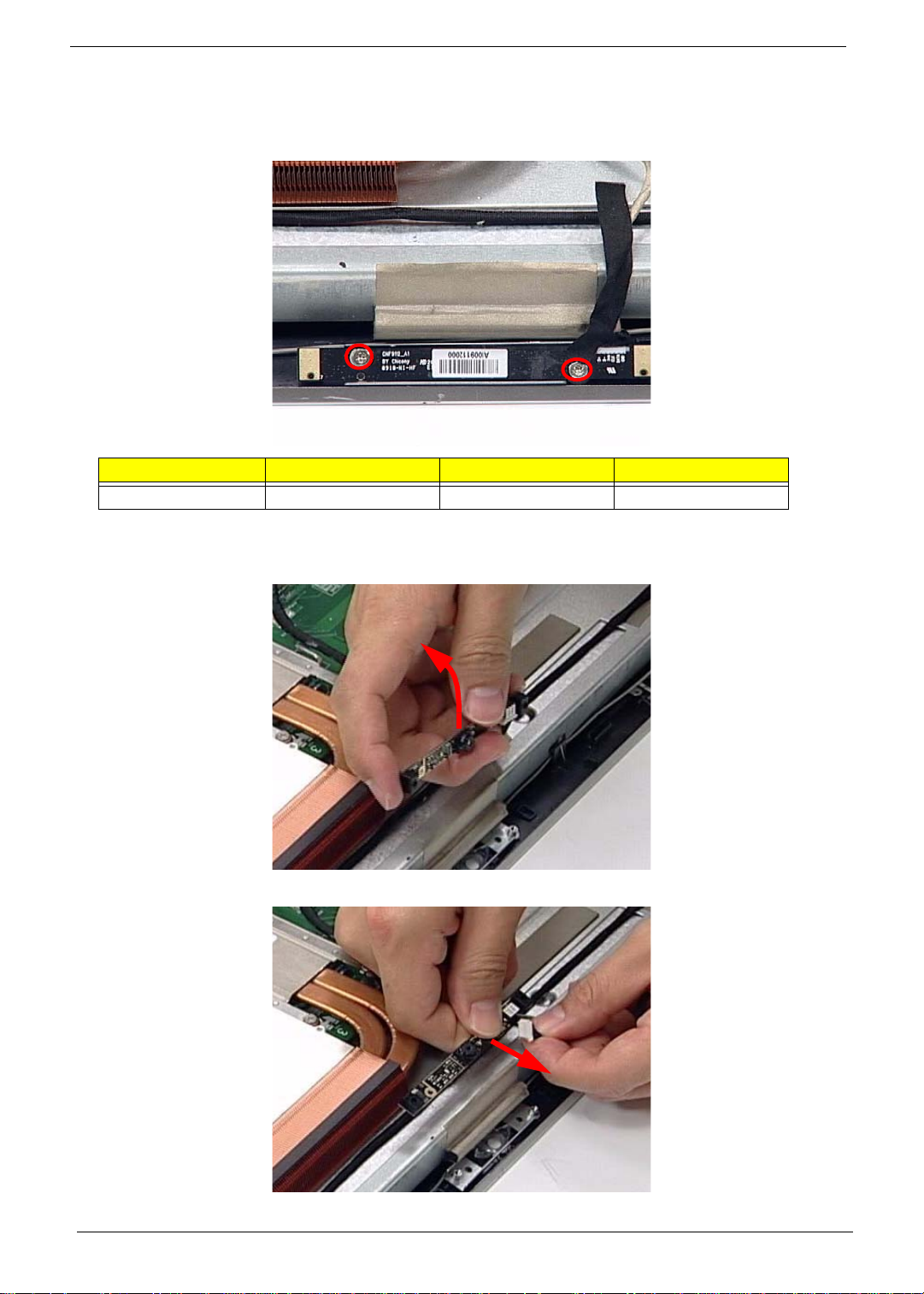
Removing the TV Tuner Board
1. See “Removing the Web Camera Board” on page 56.
2. Disconnect one (1) cable from the TV Tuner Board.
3. Remove one (1) securing screw from the TV Tuner Board.
Step Size Quantity Screw Type
TV Tuner Board 1
4. Lift the TV Tuner Board away as shown.
Chapter 3 57
Page 68

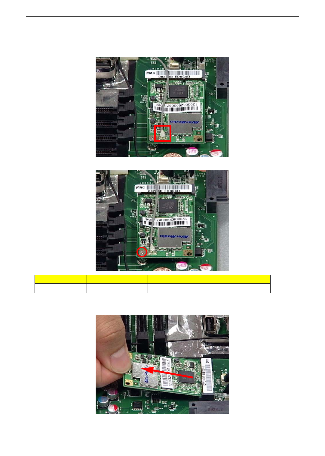
Removing the WLAN Board
1. See “Removing the TV Tuner Board” on page 57.
2. Disconnect two (2) cables from the WLAN Board as shown.
3. Remove one (1) securing screw from the WLAN Board.
Step Size Quantity Screw Type
WLAN Board 1
4. Lift the WLAN Board clear of the device.
58 Chapter 3
Page 69

Removing the CPU Fan
1. See “Removing the WLAN Board” on page 58.
2. Disconnect the CPU fan cable from the Mainboard.
3. Remove two (2) securing screws from the Fan.
Step Size Quantity Screw Type
CPU Fan SCREW M2.5*6 2
4. Lift the CPU Fan clear of the device.
Chapter 3 59
Page 70
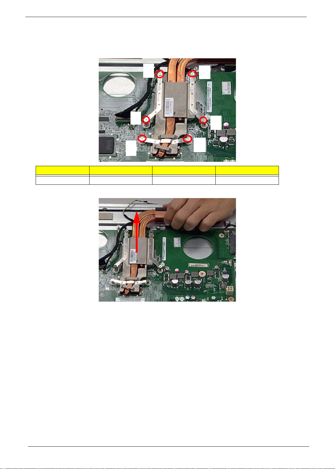
Removing the Thermal Module
1. See “Removing the CPU Fan” on page 59.
2. Remove six (6) captive screws from the Thermal Module in ascending order from 1 to 6.
1
6
Step Size Quantity Screw Type
Thermal Module 6
3. Lift the Thermal Module clear of the device.
4
2
3
5
60 Chapter 3
Page 71

Removing the CPU
1. See “Removing the Thermal Module” on page 60.
2. Push the CPU latch down (1) and out (2) to unlock the processor housing.
1
2
3. Lift the cover of the housing.
4. Remove the CPU.
Chapter 3 61
Page 72

Removing the Mainboard Cables
1. See “Removing the CPU” on page 61.
2. Remove seventeen (17) cables from the Mainboard as shown.
1
2
3
4
10
5
6
7
8
9
Item Description
1 LVDS Cable
2 CCD Cable
3 Inverter Cable
4MIC Cable
5 ODD Button Cable
6
7 Home Button Cable
8 Card Reader Cable
9 IR Cable
10 Touch Screen
11 Audio Cable
12 TV Tuner Cable
13
14 USB Cable
15 Speaker Cable
16 SAT A Cable
17 LED Light
11
12
13
14
15
16
17
62 Chapter 3
Page 73
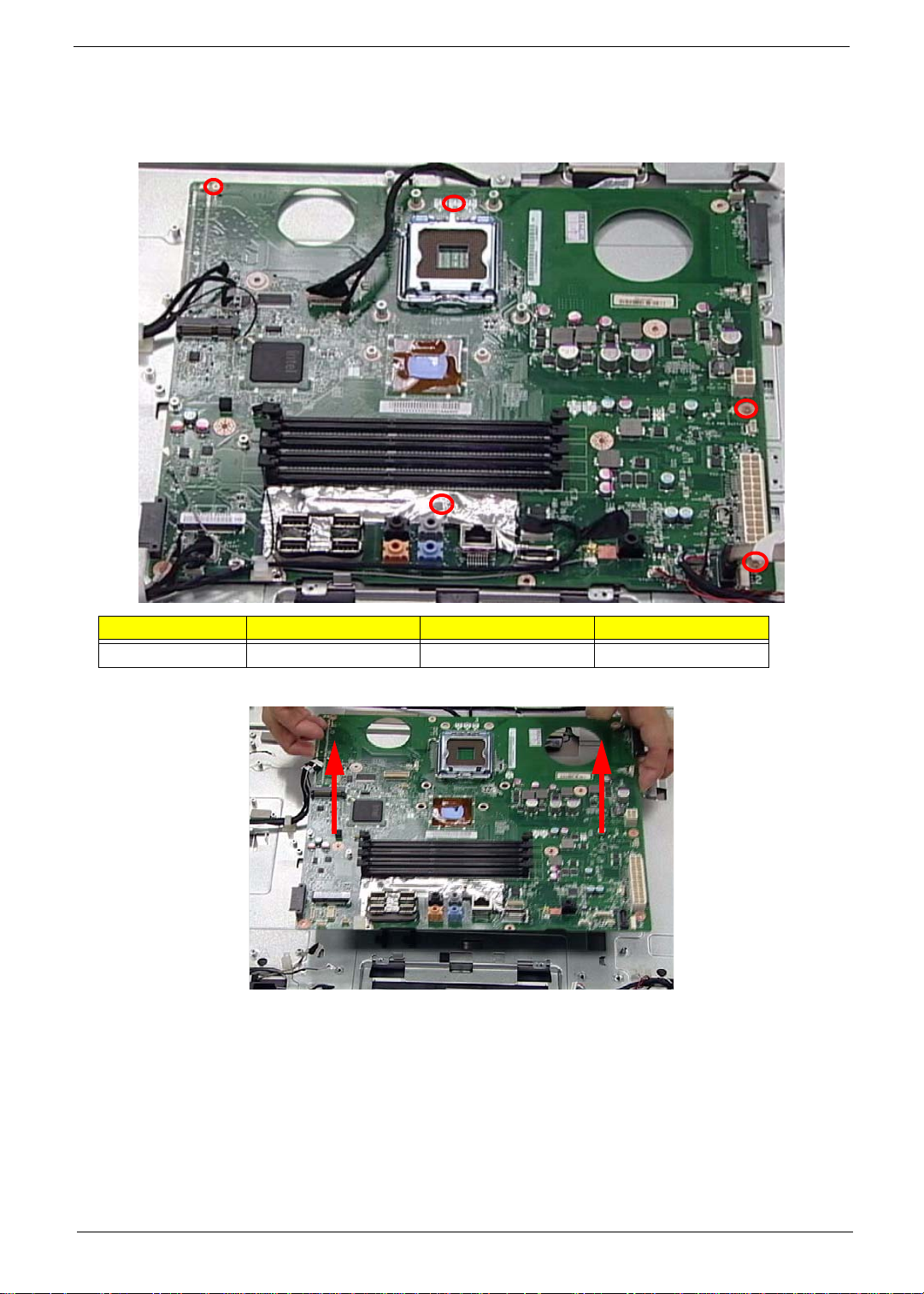
Removing the Mainboard
1. See “Removing the Mainboard Cables” on page 62.
2. Remove five (5) securing screws from the Mainboard as shown.
Step Size Quantity Screw Type
Mainboard SCREW M 2.5*4MM 5
3. Carefully lift the Mainboard clear of the device.
Chapter 3 63
Page 74
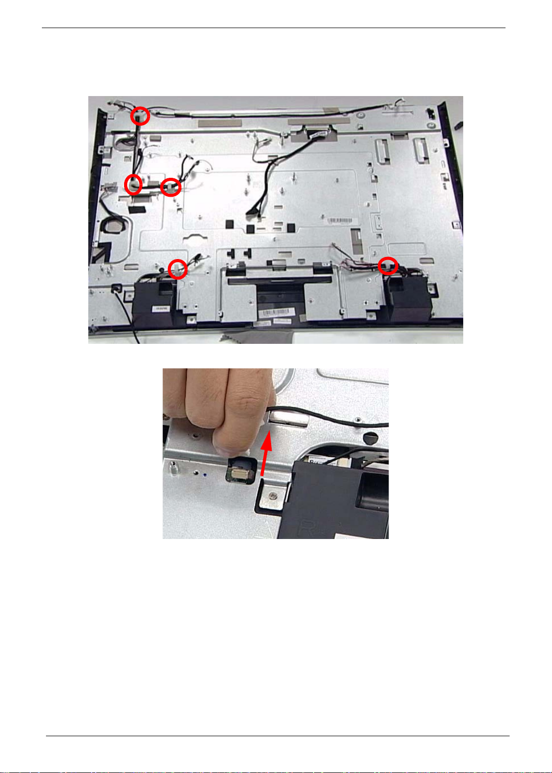
Removing the LCD Assembly
1. See “Removing the Mainboard” on page 63.
2. Release five (5) cable locks as shown.
3. Disconnect the Home Button Cable.
64 Chapter 3
Page 75

4. Remove the LVDS Mylar (1) and disconnect the cable (2) as shown.
1
5. Disconnect the left and right Control board Cables.
2
Chapter 3 65
Page 76
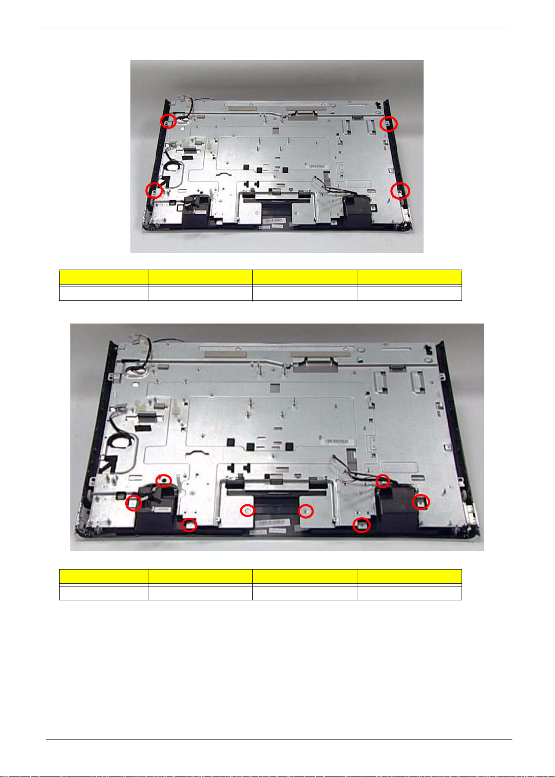
6. Remove four (4) securing screws from the LCD Bracket.
Step Size Quantity Screw Type
LCD Bracket SCREW M2.5*4 4
7. Remove nine (9) securing screws from the LCD Bezel.
Step Size Quantity Screw Type
LCD Bezel SCREW M2.5*4 9
66 Chapter 3
Page 77
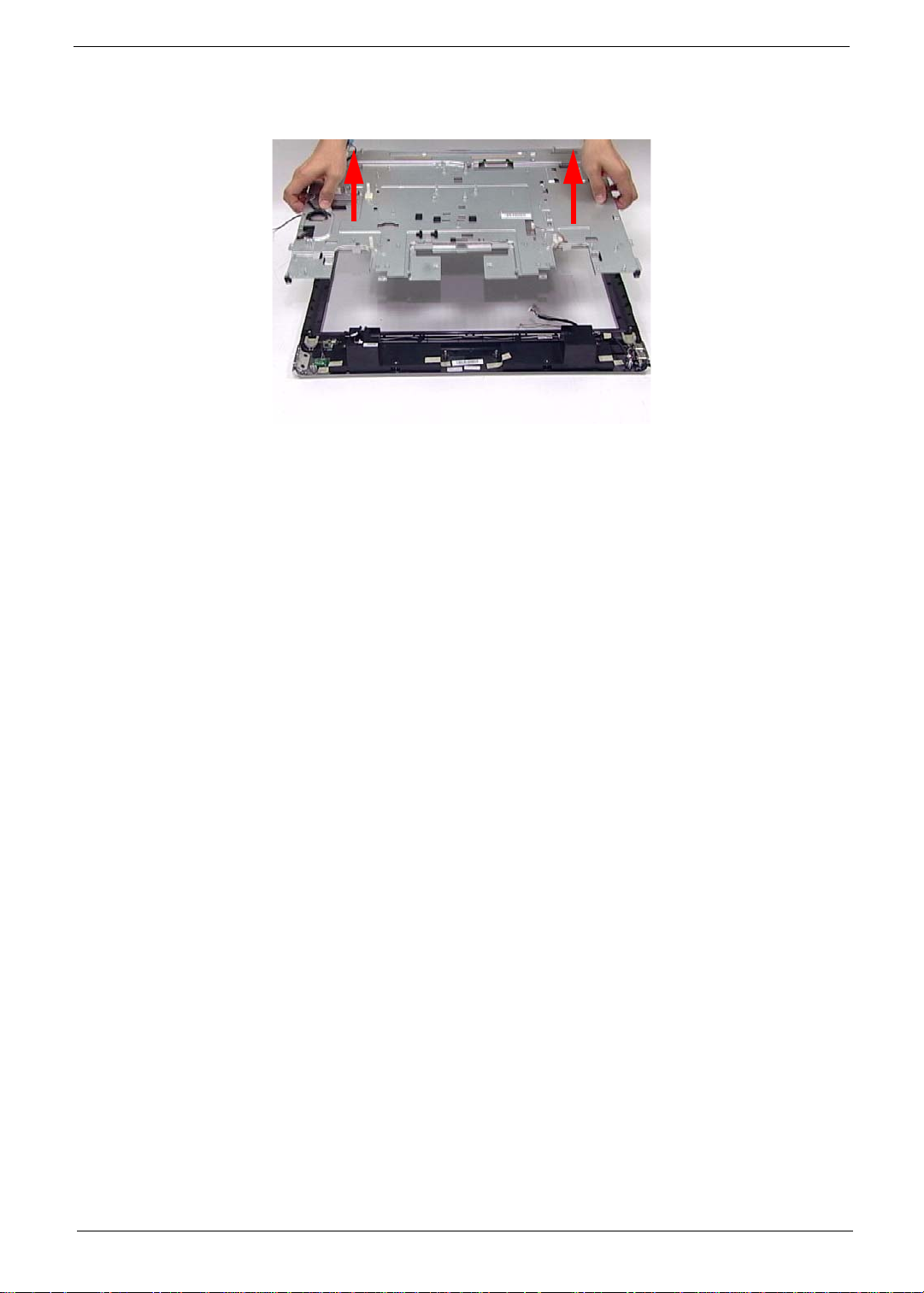
8. Lift the LCD Assembly clear of the device.
WARNING:When lifting the LCD Assembly, do not touch the Camera Modules located at the top left and top
right corners of the device. Doing so will damage the touch screen function.
Chapter 3 67
Page 78
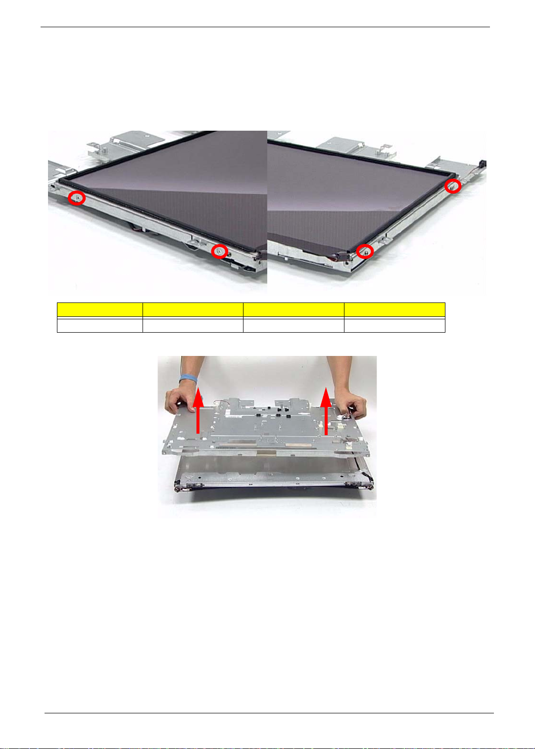
Removing the LCD Bracket
1. See “Removing the LCD Assembly” on page 64.
2. Place the LCD Assembly on an anti-static mat so the touch sensors are elevated above the work surface.
WARNING:Do not place the LCD Panel face down without an anti-static mat underneath. The touch sensors
located at the top left and top right corners will be damaged if the LCD Panel is placed face down.
3. Remove four (4) securing screws from the LCD Panel as shown.
Step Size Quantity Screw Type
LCD Bracket 4
4. Separate the LCD Bracket from the LCD Panel, while guiding the cables through the frame.
68 Chapter 3
Page 79
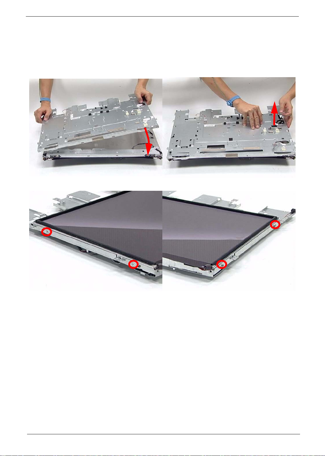
Reassembly Procedure
Replacing the LCD Bracket
1. Replace one side of the LCD Bracket (1), while using the opposite hand to pull the cables through the frame
(2). Make sure the frame is fitted securely on top of the panel.
1
2. Secure the LCD Panel to the frame using four (4) screws.
2
Chapter 3 69
Page 80
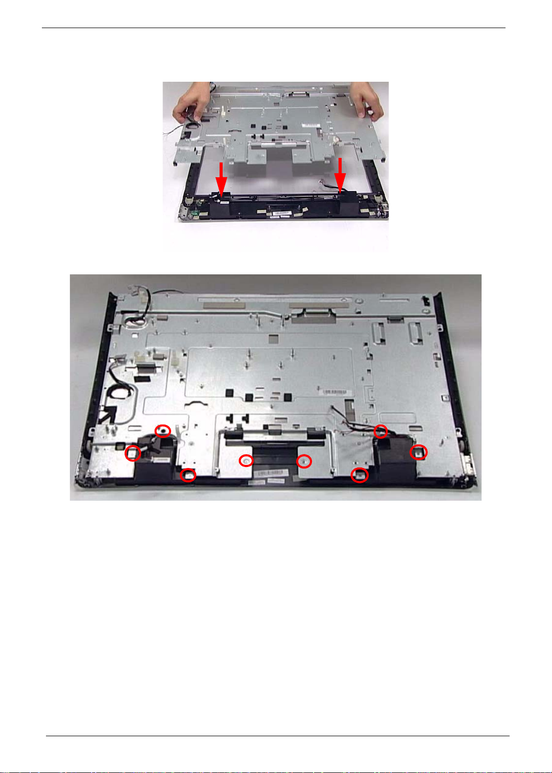
Replacing the LCD Assembly
1. Carefully place the LCD Assembly in the LCD Bezel.
2. Secure the LCD Bezel using nine (9) screws.
70 Chapter 3
Page 81
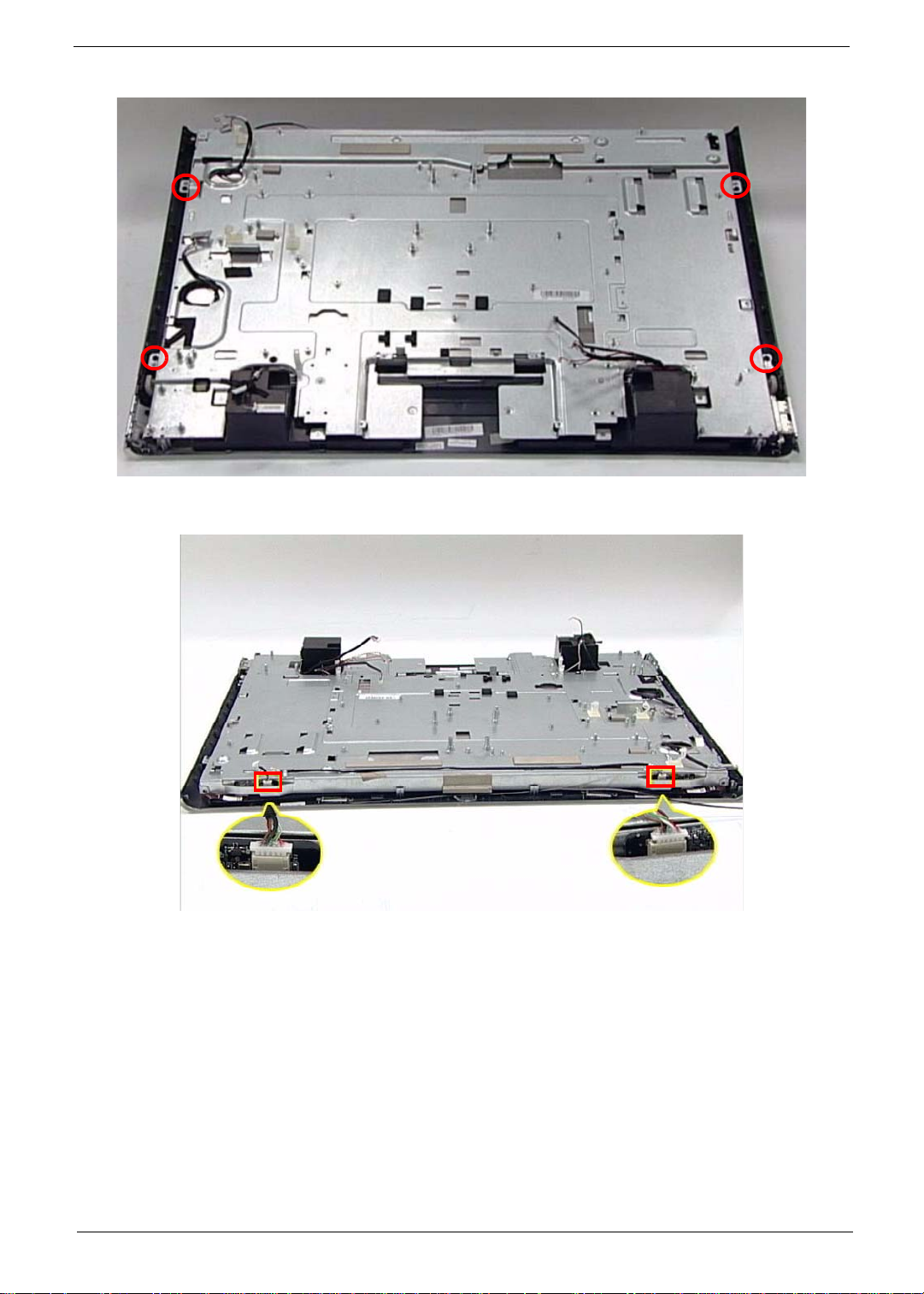
3. Secure the LCD Bracket using four (4) screws.
4. Connect the left and right Control Board Cables.
Chapter 3 71
Page 82

5. Replace the LVDS Mylar (1) and connect the cable (2).
1
6. Connect the Home Button Cable
2
7. Lock the five (5) cable locks as shown.
72 Chapter 3
Page 83

Replacing the Mainboard
1. Carefully replace the Mainboard, while lining up the six (6) guide pins un derneath.
2. Secure the Mainboard in place using five (5) screws as shown.
Chapter 3 73
Page 84
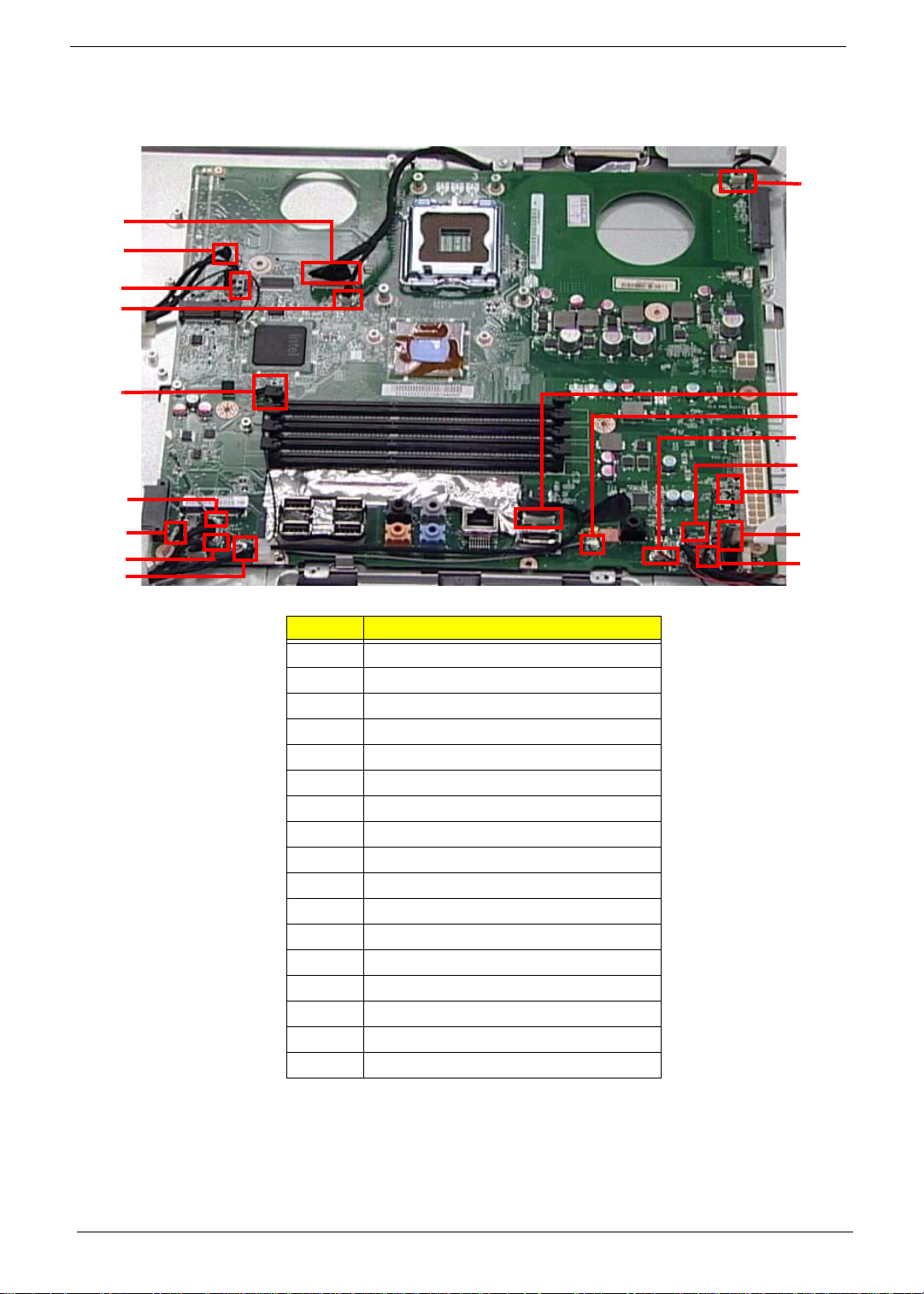
Replacing the Mainboard Cables
1. Secure the Mainboard by connecting seventeen (17) cables.
1
2
3
4
10
5
6
7
8
9
Item Description
1 LVDS Cable
2 CCD Cable
3 Inverter Cable
4MIC Cable
5 ODD Button Cable
6
7 Home Button Cable
8 Card Reader Cable
9 IR Cable
10 Touch Screen
11 Audio Cable
12 TV Tuner Cable
13
14 USB Cable
15 Speaker Cable
16 SAT A Cable
17 LED Light
11
12
13
14
15
16
17
74 Chapter 3
Page 85

Replacing the CPU
1. Place the CPU in the CPU housing.
2. Close the cover of the housing.
3. Push the CPU latch down (1) and in (2) to lock the processor housing.
1
2
Chapter 3 75
Page 86
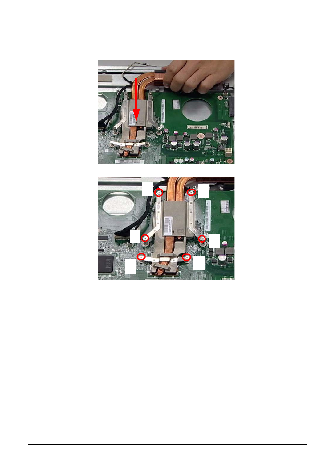
Replacing the Thermal Module
IMPORTANT:Ensure a heat pad is in place before replacing the Thermal Module.
1. Replace the Thermal Module as shown.
2. Secure the module by tightening six (6) captive screws in ascending order from 1 to 6.
6
1
4
2
3
5
76 Chapter 3
Page 87
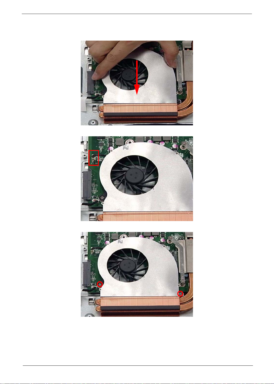
Replacing the CPU Fan
1. Using both hands, align the screw holes on the fan and LCD Module and place the fan on the Thermal Module.
2. Connect the CPU Fan cable to the Mainboard connector.
3. Secure the Fan using two (2)screws as shown.
Chapter 3 77
Page 88
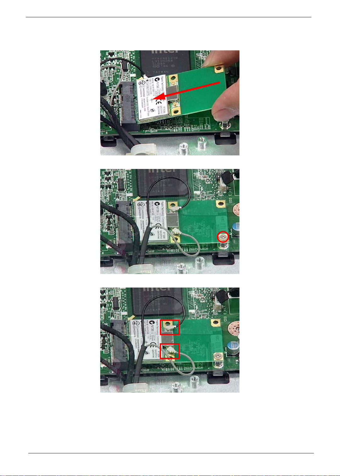
Replacing the WLAN Board
1. Push the WLAN Board into the slot.
2. Secure the WLAN Board using one (1) screw as shown.
3. Connect two (2) cables to secure the WLAN Board.
NOTE: The gray and black cables must be attached to the proper connector to function properly.
78 Chapter 3
Page 89
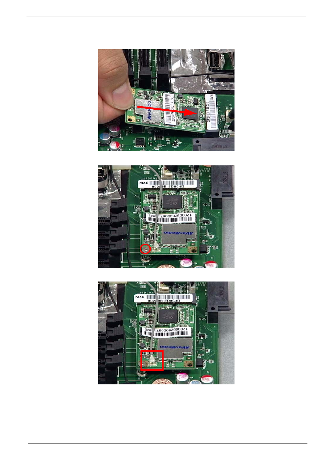
Replacing the TV Tuner Board
1. Push the TV Tuner Board into the slot.
2. Secure the TV Tuner Board using one (1) screw as shown.
3. Connect one (1) cable to secure the TV Tuner Board.
Chapter 3 79
Page 90

Replacing the Web Camera Board
1. Connect the cable underneath the Web Camera board.
CAUTION: Do not use excessive force when handling the Web Camera Board.
2. Turn the Board over and place it in the device.
3. Secure the Web Camera Board using two (2) screws as shown.
80 Chapter 3
Page 91
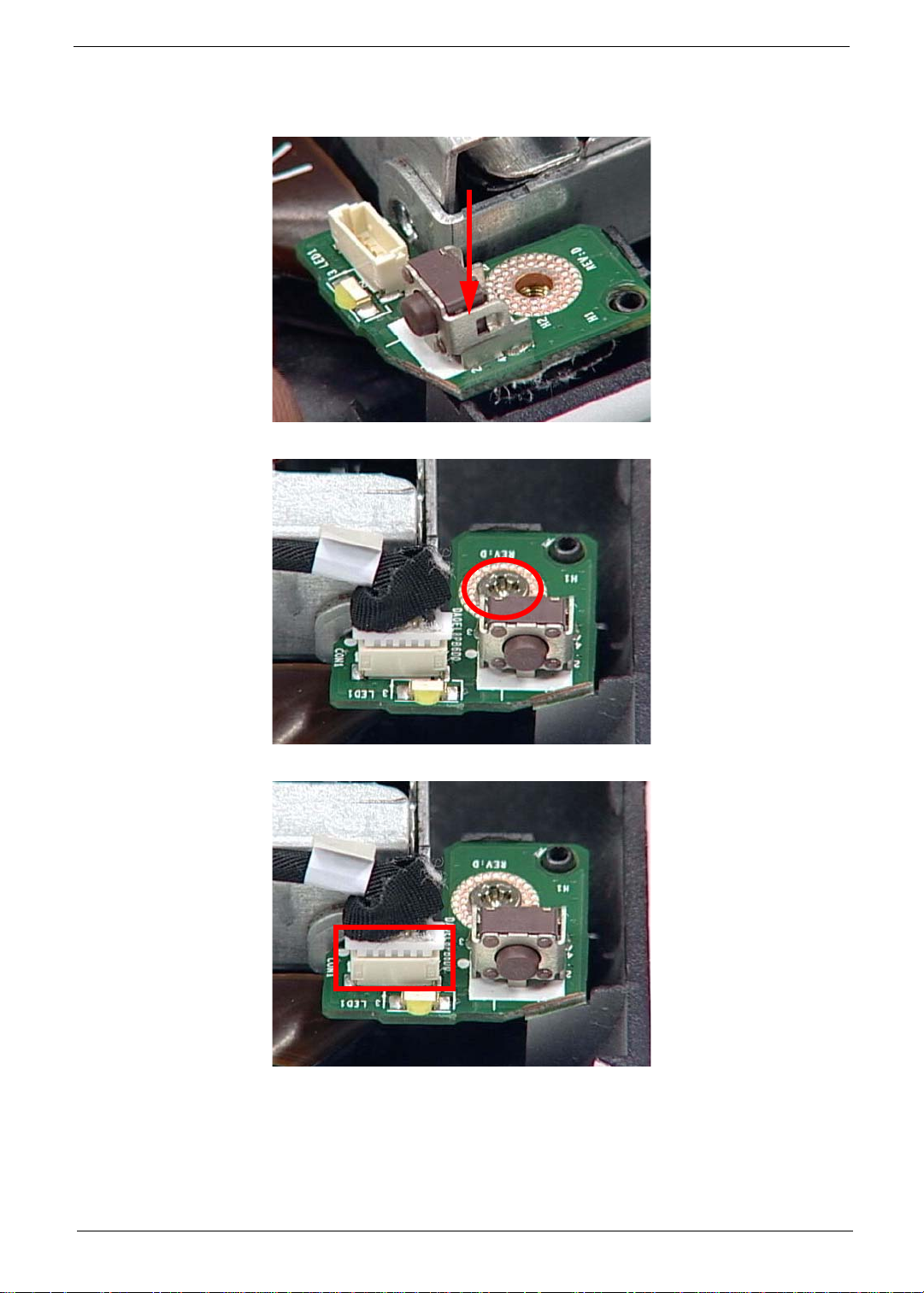
Replacing the Home Button Board
1. Replace the Home Button Board, while lining up the guide pin underneath.
2. Secure the Home Button Board using one screw.
3. Connect one cable to secure the Home Button Board.
Chapter 3 81
Page 92
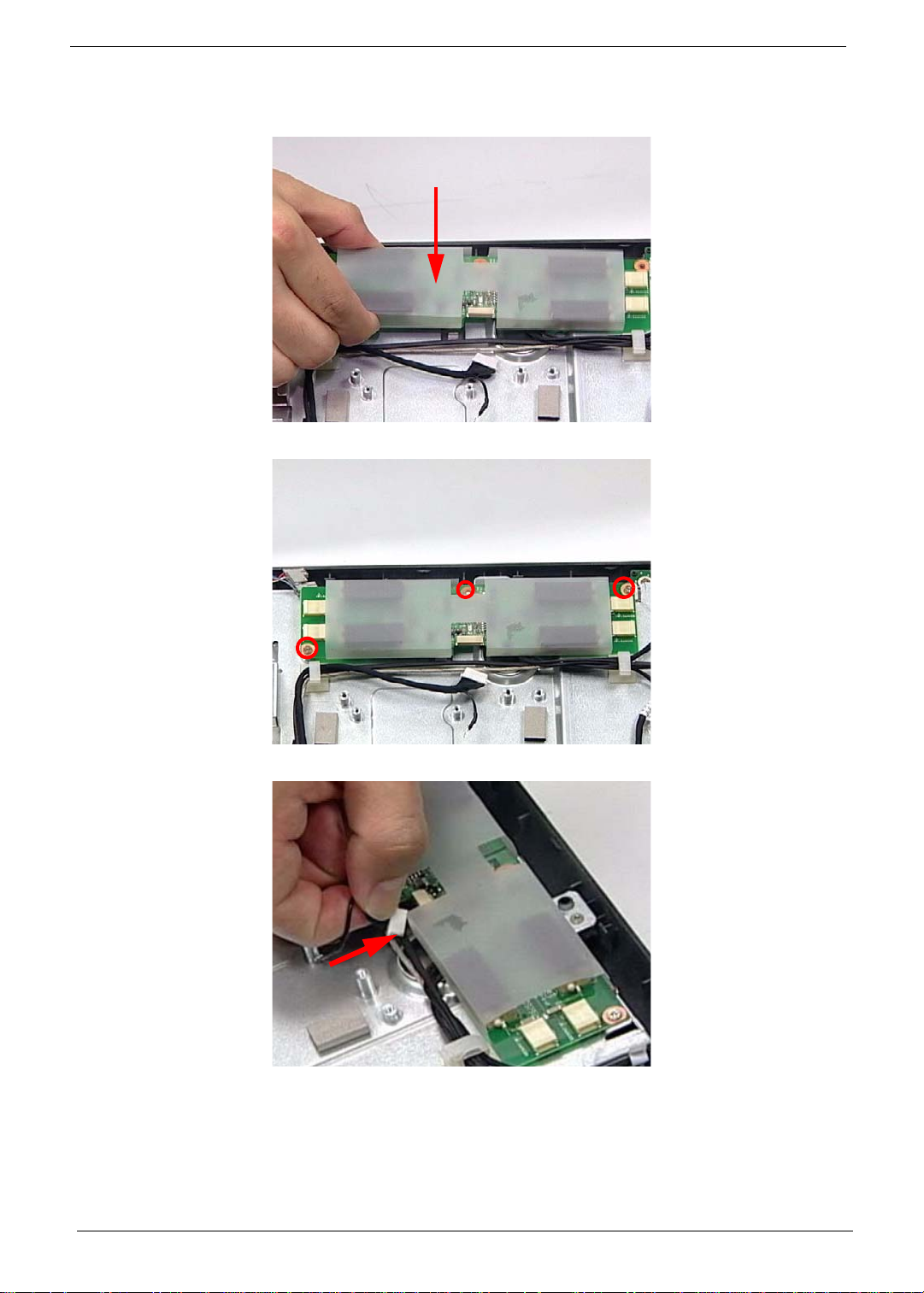
Replacing the Inverter Board
1. Replace the Inverter Board as shown.
2. Secure the Inverter Board using three (3) screws.
3. Connect the Mainboard cable to the Inverter Board as shown.
82 Chapter 3
Page 93
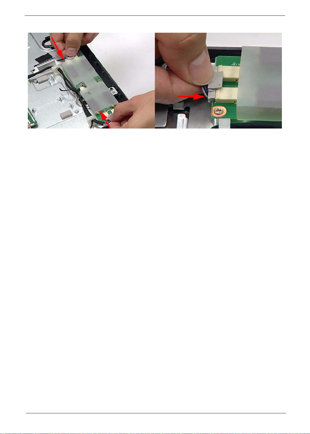
4. Connect the cables on either side of the Inverter Board.
Chapter 3 83
Page 94
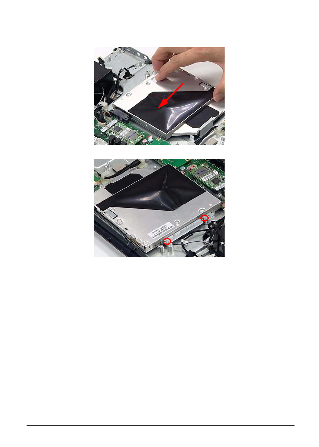
Replacing the ODD Module
1. Slide the ODD Module into the flange.
2. Secure the ODD Module using two (2) screws.
84 Chapter 3
Page 95
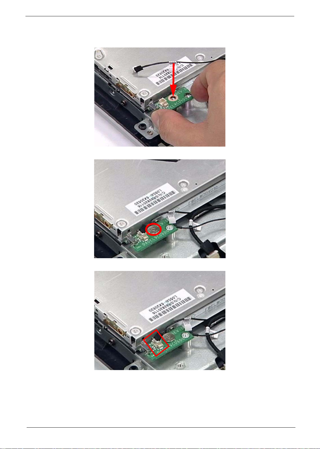
Replacing the ODD Button Board
1. Replace the ODD Button Board while lining up the guide pin underneath.
2. Secure the ODD Button Board using one (1) screw.
3. Connect one (1) cable to secure the ODD Button Board as shown.
Chapter 3 85
Page 96
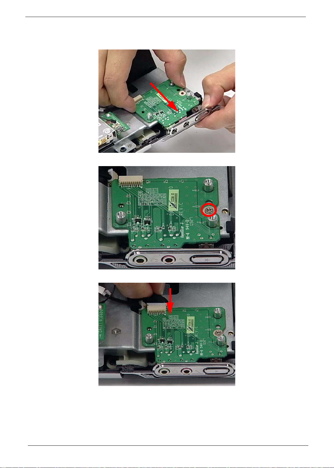
Replacing the Audio Board
1. Replace the Audio Board by lining up the ports with the bracket and three (3) guide pins as shown.
2. Secure the Audio Board using one (1) screw.
3. Connect the Audio Board Cable.
86 Chapter 3
Page 97

Replacing the Card Reader Board
1. Replace the Card Reader Board.
2. Secure the Card Reader Board using three (3) screws.
3. Connect the Card Reader Board Cable.
Chapter 3 87
Page 98

Replacing the Control Board
1. Replace the Control Board.
2. Secure the Control Board using two (2) screws.
3. Connect three (3) cables to secure the Control Board as shown.
88 Chapter 3
Page 99

Replacing the SSD
1. Slide the SSD into the flange.
2. Secure the SSD using one (1) screw as shown.
Chapter 3 89
Page 100
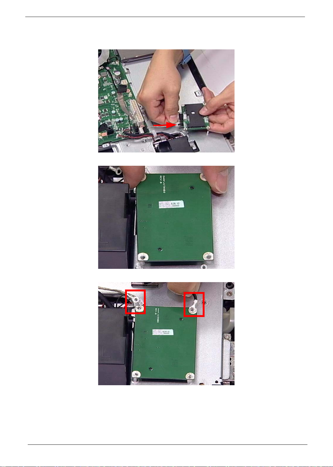
Replacing the B-CAS Board
1. Connect the cable underneath the B-CAS Board.
2. Turn the B-CAS Board over and replace it.
3. Install the USB and HDD grounding cables as shown.
90 Chapter 3
 Loading...