


 Loading...
Aspire Z5600/Z5610 Series
Service Guide
Service guide files and updates are available on the ACER/CSD web; for more information, please refer to http://csd.acer.com.tw
PRINTED IN TAIWAN

Revision History
Please refer to the table below for the updates made on Aspire Z5600/Z5610 Series service guide.
Date |
Chapter |
Updates |
|
|
|
|
|
|
|
|
|
|
|
|
II

Copyright
Copyright © 2009 by Acer Incorporated. All rights reserved. No part of this publication may be reproduced, transmitted, transcribed, stored in a retrieval system, or translated into any language or computer language, in any form or by any means, electronic, mechanical, magnetic, optical, chemical, manual or otherwise, without the prior written permission of Acer Incorporated.
Disclaimer
The information in this guide is subject to change without notice.
Acer Incorporated makes no representations or warranties, either expressed or implied, with respect to the contents hereof and specifically disclaims any warranties of merchantability or fitness for any particular purpose. Any Acer Incorporated software described in this manual is sold or licensed "as is". Should the programs prove defective following their purchase, the buyer (and not Acer Incorporated, its distributor, or its dealer) assumes the entire cost of all necessary servicing, repair, and any incidental or consequential damages resulting from any defect in the software.
Acer is a registered trademark of Acer Corporation. Intel is a registered trademark of Intel Corporation.
Pentium and Pentium II/III are trademarks of Intel Corporation.
Other brand and product names are trademarks and/or registered trademarks of their respective holders.
III

Conventions
The following conventions are used in this manual:
SCREEN MESSAGES |
Denotes actual messages that appear |
|
on screen. |
|
|
NOTE |
Gives bits and pieces of additional |
|
information related to the current |
|
topic. |
|
|
WARNING |
Alerts you to any damage that might |
|
result from doing or not doing specific |
|
actions. |
|
|
CAUTION |
Gives precautionary measures to |
|
avoid possible hardware or software |
|
problems. |
|
|
IMPORTANT |
Reminds you to do specific actions |
|
relevant to the accomplishment of |
|
procedures. |
|
|
IV

Preface
Before using this information and the product it supports, please read the following general information.
1.This Service Guide provides you with all technical information relating to the BASIC CONFIGURATION decided for Acer's "global" product offering. To better fit local market requirements and enhance product competitiveness, your regional office MAY have decided to extend the functionality of a machine (e.g. add-on card, modem, or extra memory capability). These LOCALIZED FEATURES will NOT be covered in this generic service guide. In such cases, please contact your regional offices or the responsible personnel/channel to provide you with further technical details.
2.Please note WHEN ORDERING FRU PARTS, that you should check the most up-to-date information available on your regional web or channel. If, for whatever reason, a part number change is made, it will not be noted in the printed Service Guide. For ACER-AUTHORIZED SERVICE PROVIDERS, your Acer office may have a DIFFERENT part number code to those given in the FRU list of this printed Service Guide. You MUST use the list provided by your regional Acer office to order FRU parts for repair and service of customer machines.
V

VI

Table of Contents
System Specifications |
1 |
Features . . . . . . . . . . . . . . . . . . . . . . . . . . . . . . . . . . . . . . . . . . . . . . . . . . . . . . . . . . . .1 System Block Diagram . . . . . . . . . . . . . . . . . . . . . . . . . . . . . . . . . . . . . . . . . . . . . . . . .3 Your Acer Computer tour . . . . . . . . . . . . . . . . . . . . . . . . . . . . . . . . . . . . . . . . . . . . . . .4 Front View . . . . . . . . . . . . . . . . . . . . . . . . . . . . . . . . . . . . . . . . . . . . . . . . . . . . . . .4 Right View . . . . . . . . . . . . . . . . . . . . . . . . . . . . . . . . . . . . . . . . . . . . . . . . . . . . . . .5 Left View . . . . . . . . . . . . . . . . . . . . . . . . . . . . . . . . . . . . . . . . . . . . . . . . . . . . . . . .6 Rear View . . . . . . . . . . . . . . . . . . . . . . . . . . . . . . . . . . . . . . . . . . . . . . . . . . . . . . .7 Using the Keyboard . . . . . . . . . . . . . . . . . . . . . . . . . . . . . . . . . . . . . . . . . . . . . . . . . . .8 Windows Keys . . . . . . . . . . . . . . . . . . . . . . . . . . . . . . . . . . . . . . . . . . . . . . . . . . .9 Hardware Specifications and Configurations . . . . . . . . . . . . . . . . . . . . . . . . . . . . . . .10
System Utilities |
17 |
BIOS Setup Utility . . . . . . . . . . . . . . . . . . . . . . . . . . . . . . . . . . . . . . . . . . . . . . . . . . . .17
Navigating the BIOS Utility . . . . . . . . . . . . . . . . . . . . . . . . . . . . . . . . . . . . . . . . .17
Information . . . . . . . . . . . . . . . . . . . . . . . . . . . . . . . . . . . . . . . . . . . . . . . . . . . . .18
Main . . . . . . . . . . . . . . . . . . . . . . . . . . . . . . . . . . . . . . . . . . . . . . . . . . . . . . . . . .19
Advanced . . . . . . . . . . . . . . . . . . . . . . . . . . . . . . . . . . . . . . . . . . . . . . . . . . . . . .23
Security . . . . . . . . . . . . . . . . . . . . . . . . . . . . . . . . . . . . . . . . . . . . . . . . . . . . . . . .26
PC Health . . . . . . . . . . . . . . . . . . . . . . . . . . . . . . . . . . . . . . . . . . . . . . . . . . . . . .29
Power . . . . . . . . . . . . . . . . . . . . . . . . . . . . . . . . . . . . . . . . . . . . . . . . . . . . . . . . .30
Boot . . . . . . . . . . . . . . . . . . . . . . . . . . . . . . . . . . . . . . . . . . . . . . . . . . . . . . . . . . .31
Exit . . . . . . . . . . . . . . . . . . . . . . . . . . . . . . . . . . . . . . . . . . . . . . . . . . . . . . . . . . .32
Machine Disassembly and Replacement |
33 |
Disassembly Requirements . . . . . . . . . . . . . . . . . . . . . . . . . . . . . . . . . . . . . . . . . . . .33
General Information . . . . . . . . . . . . . . . . . . . . . . . . . . . . . . . . . . . . . . . . . . . . . . . . . .33
Pre-disassembly Instructions . . . . . . . . . . . . . . . . . . . . . . . . . . . . . . . . . . . . . . .33
Disassembly Process . . . . . . . . . . . . . . . . . . . . . . . . . . . . . . . . . . . . . . . . . . . . . . . . .34
Disassembly Flowchart . . . . . . . . . . . . . . . . . . . . . . . . . . . . . . . . . . . . . . . . . . . .34
Removing the RAM Cover . . . . . . . . . . . . . . . . . . . . . . . . . . . . . . . . . . . . . . . . .35
Removing the Hinge Cover . . . . . . . . . . . . . . . . . . . . . . . . . . . . . . . . . . . . . . . . .36
Removing the RAM . . . . . . . . . . . . . . . . . . . . . . . . . . . . . . . . . . . . . . . . . . . . . . .37
Removing the Rear Covers . . . . . . . . . . . . . . . . . . . . . . . . . . . . . . . . . . . . . . . . .38
Removing the Back Cover . . . . . . . . . . . . . . . . . . . . . . . . . . . . . . . . . . . . . . . . .39
Removing the Hinge . . . . . . . . . . . . . . . . . . . . . . . . . . . . . . . . . . . . . . . . . . . . . .41
Removing the Back Frame . . . . . . . . . . . . . . . . . . . . . . . . . . . . . . . . . . . . . . . . .42
Removing the Power Supply . . . . . . . . . . . . . . . . . . . . . . . . . . . . . . . . . . . . . . . .44
Removing the HDD Module . . . . . . . . . . . . . . . . . . . . . . . . . . . . . . . . . . . . . . . .45
Removing the B-CAS Board . . . . . . . . . . . . . . . . . . . . . . . . . . . . . . . . . . . . . . . .46
Removing the SSD Module . . . . . . . . . . . . . . . . . . . . . . . . . . . . . . . . . . . . . . . . .47
Removing the Control Board . . . . . . . . . . . . . . . . . . . . . . . . . . . . . . . . . . . . . . . .48
Removing the Card Reader Board . . . . . . . . . . . . . . . . . . . . . . . . . . . . . . . . . . .49
Removing the Audio Board . . . . . . . . . . . . . . . . . . . . . . . . . . . . . . . . . . . . . . . . .50
Removing the ODD Button Board . . . . . . . . . . . . . . . . . . . . . . . . . . . . . . . . . . . .51
Removing the ODD Module . . . . . . . . . . . . . . . . . . . . . . . . . . . . . . . . . . . . . . . .52
Removing the Inverter Board . . . . . . . . . . . . . . . . . . . . . . . . . . . . . . . . . . . . . . .53
Removing the Home Button Board . . . . . . . . . . . . . . . . . . . . . . . . . . . . . . . . . . .55
Removing the Web Camera Board . . . . . . . . . . . . . . . . . . . . . . . . . . . . . . . . . . .56
Removing the TV Tuner Board . . . . . . . . . . . . . . . . . . . . . . . . . . . . . . . . . . . . . .57
Removing the WLAN Board . . . . . . . . . . . . . . . . . . . . . . . . . . . . . . . . . . . . . . . .58
Removing the CPU Fan . . . . . . . . . . . . . . . . . . . . . . . . . . . . . . . . . . . . . . . . . . .59
Removing the Thermal Module . . . . . . . . . . . . . . . . . . . . . . . . . . . . . . . . . . . . . .60
Removing the CPU . . . . . . . . . . . . . . . . . . . . . . . . . . . . . . . . . . . . . . . . . . . . . . .61
VII

Table of Contents |
|
Removing the Mainboard Cables . . . . . . . . . . . . . . . . . . . . . . . . . . . . . . . . . . |
. .62 |
Removing the Mainboard . . . . . . . . . . . . . . . . . . . . . . . . . . . . . . . . . . . . . . . . |
. .63 |
Removing the LCD Assembly . . . . . . . . . . . . . . . . . . . . . . . . . . . . . . . . . . . . . |
. .64 |
Removing the LCD Bracket . . . . . . . . . . . . . . . . . . . . . . . . . . . . . . . . . . . . . . |
. .68 |
Reassembly Procedure . . . . . . . . . . . . . . . . . . . . . . . . . . . . . . . . . . . . . . . . . . . . . |
. .69 |
Replacing the LCD Bracket . . . . . . . . . . . . . . . . . . . . . . . . . . . . . . . . . . . . . . . |
. .69 |
Replacing the LCD Assembly . . . . . . . . . . . . . . . . . . . . . . . . . . . . . . . . . . . . . |
. .70 |
Replacing the Mainboard . . . . . . . . . . . . . . . . . . . . . . . . . . . . . . . . . . . . . . . . |
. .73 |
Replacing the Mainboard Cables . . . . . . . . . . . . . . . . . . . . . . . . . . . . . . . . . . |
. .74 |
Replacing the CPU . . . . . . . . . . . . . . . . . . . . . . . . . . . . . . . . . . . . . . . . . . . . . |
. .75 |
Replacing the Thermal Module . . . . . . . . . . . . . . . . . . . . . . . . . . . . . . . . . . . . |
. .76 |
Replacing the CPU Fan . . . . . . . . . . . . . . . . . . . . . . . . . . . . . . . . . . . . . . . . . |
. .77 |
Replacing the WLAN Board . . . . . . . . . . . . . . . . . . . . . . . . . . . . . . . . . . . . . . |
. .78 |
Replacing the TV Tuner Board . . . . . . . . . . . . . . . . . . . . . . . . . . . . . . . . . . . . |
. .79 |
Replacing the Web Camera Board . . . . . . . . . . . . . . . . . . . . . . . . . . . . . . . . . |
. .80 |
Replacing the Home Button Board . . . . . . . . . . . . . . . . . . . . . . . . . . . . . . . . . |
. .81 |
Replacing the Inverter Board . . . . . . . . . . . . . . . . . . . . . . . . . . . . . . . . . . . . . |
. .82 |
Replacing the ODD Module . . . . . . . . . . . . . . . . . . . . . . . . . . . . . . . . . . . . . . |
. .84 |
Replacing the ODD Button Board . . . . . . . . . . . . . . . . . . . . . . . . . . . . . . . . . . |
. .85 |
Replacing the Audio Board . . . . . . . . . . . . . . . . . . . . . . . . . . . . . . . . . . . . . . . |
. .86 |
Replacing the Card Reader Board . . . . . . . . . . . . . . . . . . . . . . . . . . . . . . . . . |
. .87 |
Replacing the Control Board . . . . . . . . . . . . . . . . . . . . . . . . . . . . . . . . . . . . . . |
. .88 |
Replacing the SSD . . . . . . . . . . . . . . . . . . . . . . . . . . . . . . . . . . . . . . . . . . . . . |
. .89 |
Replacing the B-CAS Board . . . . . . . . . . . . . . . . . . . . . . . . . . . . . . . . . . . . . . |
. .90 |
Replacing the HDD Module . . . . . . . . . . . . . . . . . . . . . . . . . . . . . . . . . . . . . . |
. .92 |
Replacing the Power Supply . . . . . . . . . . . . . . . . . . . . . . . . . . . . . . . . . . . . . . |
. .93 |
Replacing the Back Frame . . . . . . . . . . . . . . . . . . . . . . . . . . . . . . . . . . . . . . . |
. .94 |
Replacing the Hinge . . . . . . . . . . . . . . . . . . . . . . . . . . . . . . . . . . . . . . . . . . . . |
. .96 |
Replacing the Back Cover . . . . . . . . . . . . . . . . . . . . . . . . . . . . . . . . . . . . . . . |
. .97 |
Replacing the Rear Covers . . . . . . . . . . . . . . . . . . . . . . . . . . . . . . . . . . . . . . . |
. .99 |
Replacing the RAM . . . . . . . . . . . . . . . . . . . . . . . . . . . . . . . . . . . . . . . . . . . . . |
.100 |
Replacing the Hinge Cover . . . . . . . . . . . . . . . . . . . . . . . . . . . . . . . . . . . . . . . |
.101 |
Replacing the RAM Cover . . . . . . . . . . . . . . . . . . . . . . . . . . . . . . . . . . . . . . . |
.102 |
Troubleshooting |
103 |
Common Problems . . . . . . . . . . . . . . . . . . . . . . . . . . . . . . . . . . . . . . . . . . . . . . . . . .103
ODD Failure . . . . . . . . . . . . . . . . . . . . . . . . . . . . . . . . . . . . . . . . . . . . . . . . . . .104
Wireless Failure . . . . . . . . . . . . . . . . . . . . . . . . . . . . . . . . . . . . . . . . . . . . . . . .107
Camera Failure . . . . . . . . . . . . . . . . . . . . . . . . . . . . . . . . . . . . . . . . . . . . . . . . .108
Speaker Failure . . . . . . . . . . . . . . . . . . . . . . . . . . . . . . . . . . . . . . . . . . . . . . . . .109
LCD Failure . . . . . . . . . . . . . . . . . . . . . . . . . . . . . . . . . . . . . . . . . . . . . . . . . . . .111
General Troubleshooting Issues . . . . . . . . . . . . . . . . . . . . . . . . . . . . . . . . . . . .113
Intermittent Problems . . . . . . . . . . . . . . . . . . . . . . . . . . . . . . . . . . . . . . . . . . . . . . . .116
Undetermined Problems . . . . . . . . . . . . . . . . . . . . . . . . . . . . . . . . . . . . . . . . . . . . . .116
Jumper and Connector Locations |
117 |
Top View . . . . . . . . . . . . . . . . . . . . . . . . . . . . . . . . . . . . . . . . . . . . . . . . . . . . . . . . . |
.117 |
Bottom View . . . . . . . . . . . . . . . . . . . . . . . . . . . . . . . . . . . . . . . . . . . . . . . . . . . . . . |
.118 |
Clearing Password Check and BIOS Recovery . . . . . . . . . . . . . . . . . . . . . . . . . . . |
.119 |
Clearing Password Check . . . . . . . . . . . . . . . . . . . . . . . . . . . . . . . . . . . . . . . . |
.119 |
BIOS Recovery by Crisis Disk . . . . . . . . . . . . . . . . . . . . . . . . . . . . . . . . . . . . |
.120 |
FRU (Field Replaceable Unit) List |
123 |
Aspire Z5600/Z5610 Series Exploded Diagrams . . . . . . . . . . . . . . . . . . . . . . . . . . .124
Main Assembly . . . . . . . . . . . . . . . . . . . . . . . . . . . . . . . . . . . . . . . . . . . . . . . . .124
VIII

Table of Contents
FRU List . . . . . . . . . . . . . . . . . . . . . . . . . . . . . . . . . . . . . . . . . . . . . . . . . . . . . .126
Screw List . . . . . . . . . . . . . . . . . . . . . . . . . . . . . . . . . . . . . . . . . . . . . . . . . . . . .134
Model Definition and Configuration |
136 |
Aspire Z5600/Z5610 Series . . . . . . . . . . . . . . . . . . . . . . . . . . . . . . . . . . . . . . . . . . |
.136 |
Test Compatible Components |
187 |
Microsoft® Windows® 7 Environment Test . . . . . . . . . . . . . . . . . . . . . . . . . . . . . . |
.188 |
Online Support Information |
197 |
Index |
199 |
IX

Table of Contents
X
Chapter 1
System Specifications
Features
Below is a brief summary of the computer’s many features:
Operating System
•Genuine Windows® 7 Home Premium (Touch Pack)*
Platform
•Intel Core™2 Quad Processor*
•Intel Core™2 Duo Processor*
•Intel Pentium Processor*
•Intel® Celeron® processor*
•Intel Eaglelake G45(B/S)+ICH10(B/S)*
Dimensions
•570 (W) x 484.0 (H) x 84.6 (D) mm
System Memory
•Up to 8 GB of DDR3 1066/1333 MHz (dual-channel support on four DIMMs)*
Display
•23" Full HD 1920 x 1080 pixel resolution, high brightness TFT LCD
•16:9 aspect ratio
•5 ms response time
•16.7 million colors
•1000:1 (ACM) contrast ratio
•Integrated Windows® 7 compliant multi-touch capable optical solution
TV Tuner
•Hybrid analog (NTSC/PAL/SECAM) and digital (DVB-T or ATSC format) TV-tuner card, supporting software MPEG-2 stream encoding*
Storage subsystem
•Hard Drive
•SATA 3 Gb/s hard disk up to 1 TB*
•SATA 3 Gb/s hard disk up to 1 TB with SSD NAND flash module up to 64 GB*
•Desktop Optical Disk Drive
Chapter 1 |
1 |

•SuperMulti with Labelflash™ technologyDVD-ROM*
Communication
•Built-in 1 MP high-def webcam with 1280 x 800 resolution image capture
•Built-in microphone
•Gigabit Ethernet, Wake-on-LAN ready
•WLAN*
•802.11b/g/Draft-N
•WPAN*
•Bluetooth® 2.1+EDR (Enhanced Data Rate)
Graphics
•Intel® GMA X4500HD (Intel® G45) (Aspire Z5600)
•ATI Radeon™ HD 4670 with 1 GB DDR3 Memory (Aspire Z5610)
•ATI Radeon™ HD 4570 with 512 MB DDR2 Memory (Aspire Z5610)
I/O interface
•Two USB 2.0 ports
•Multi-in-1 card reader
•High-definition headphone and microphone jacks
•Ambient light switch
•BCAS card Reader Slot (Japan only)
•Four USB 2.0 ports
•DC-in jack
•Ethernet (RJ-45) port
•Four audio ports
•eSATA port
•IR blaster port2 (bundle with TV tuner card)
•TV-tuner port2
Environment
•Temperature:
•Operating: 5 °C to 35 °C
•Non-operating: -20 °C to 65 °C
•Humidity (non-condensing):
•Operating: 20% to 80%
•Non-operating: 20% to 80%
NOTE: Items marked with * denote only selected models.
NOTE: The specifications listed above are for reference only. The exact configuration of your PC depends on the model purchased.
2 |
Chapter 1 |
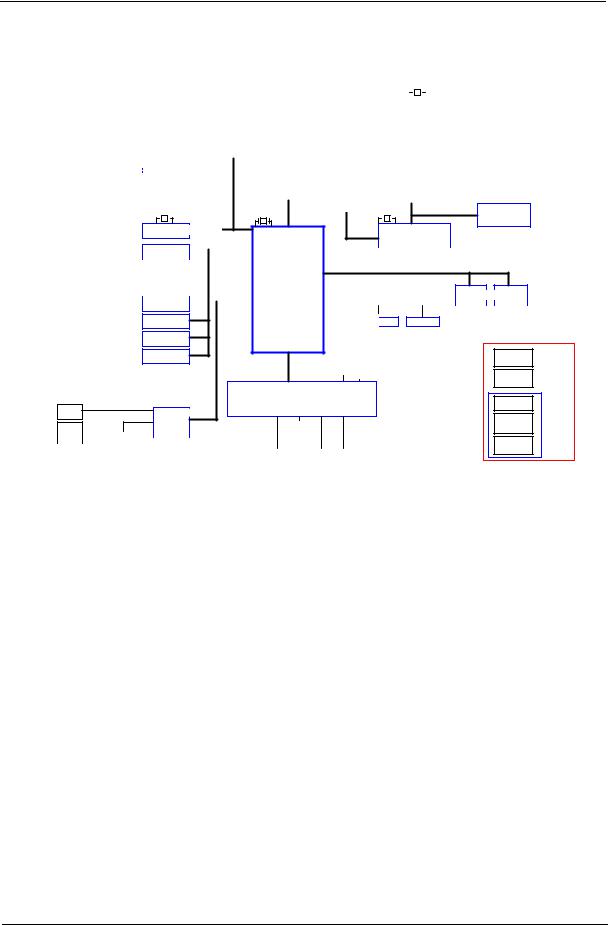
System Block Diagram
VCC_CORE |
|
|
|
|
|
|
|
|
|
|
|
|
|
|
|
|
|
|
|
|
|
|
|
|
|
|
|
|
|
|
|
|
|
|
|
|
|
|
|
|
|
|
|
|
|
|
|
|
|
|
|
Y1 |
14.318MHZ |
||||||
|
|
|
|
|
|
|
|
|
|
|
|
|
|
|
|
|
|
|
|
|
|
|
|
|
|
|
|
|
|
GMCH_CORE |
|
|
|
|
|
|
|
|
|
|
|
Intel |
|
|
|
|
|
|
|
|
|
|
|
|
|
|
|
|
|
|
|
|
|
|
|
|
|
|
|
|
|
|
|
|
CLOCK GENERATOR |
||||||||||||||
|
|
|
|
|
|
|
|
|
|
|
|
|
|
|
|
||||||||||||||
|
|
|
|
|
|
|
|
|
|
|
Yorkfield/Wolfdale |
|
|
|
|
||||||||||||||
|
|
|
|
|
|
|
|
|
|
|
|
|
|
|
|
|
|
|
CK505 |
||||||||||
VCC1.1 |
|
|
|
|
|
|
|
|
|
|
Q9000/E8000 |
|
|
|
|
|
|
|
|
||||||||||
|
|
|
|
|
|
|
|
|
|
|
|
|
|
|
|
|
|
CV193 |
|||||||||||
VCC1.2 |
|
|
|
|
|
|
|
|
|
|
|
LGA775 |
|
|
|
|
14.318MHz |
|
|
|
|
|
|
Page 2 |
|||||
|
|
|
|
|
|
|
|
|
|
|
|
|
|
|
|
|
|
|
|
|
|||||||||
|
|
|
|
|
|
|
|
|
|
|
|
|
|
|
|
|
|
|
|
|
|
|
|
|
|
|
|||
VCC1.5 |
|
|
|
|
|
|
|
|
|
|
|
|
Page 3,4 |
|
|
|
|
|
|
|
|
|
|
|
|
|
|
|
|
1.5VSUS |
|
|
|
|
|
|
|
|
|
|
|
|
FSB(800/1067/1333HZ) |
|
|
|
|
|
|
|
|
|
|
|
|
|
|||
|
|
|
|
|
|
|
|
SATA 4 |
|
|
|
|
800/1067 MHZ DDR III |
|
CH A: DDRIII-UDIMM0/1 |
|
|
||||||||||||
VCC3 |
|
SATA - HDD(2.5) |
|
|
|
|
|
|
|
|
CH B: DDRIII-UDIMM0/1 |
|
|
||||||||||||||||
|
|
|
|
|
|
|
|
|
|
|
|
|
|
Page 14,15,16,17 |
|
|
|||||||||||||
3V_STBY |
|
|
|
|
|
Page 22 |
SATA 1 |
|
|
NB |
|
|
|
|
|
|
|
|
|
|
|
|
|
|
|
|
|||
|
|
|
|
|
|
|
|
|
|
|
|
|
|
|
|
|
|
|
|
|
|
|
|
|
|||||
|
|
|
|
|
|
|
|
|
|
|
|
|
|
|
|
|
|
|
|
|
|
|
|
|
|||||
|
|
SATA - HDD(3.5) |
|
|
|
Eaglelake |
|
|
|
|
|
|
|
|
|
|
|
|
|
|
|
|
|||||||
VCC5 |
|
|
|
|
|
Page 22 |
|
|
|
|
G45/P43 |
PCI-E 2.0 16X |
|
MXM CONNECTOR |
|
||||||||||||||
5V_STBY |
|
SATA - ODD |
SATA 2 |
|
|
|
1254 pin |
|
|
|
|
|
|
|
|
|
|
|
|
|
|
|
|
||||||
|
|
|
|
|
|
|
|
|
|
|
|
|
|
|
|
|
|
|
|
|
|
||||||||
|
|
|
|
|
|
|
Page 5,7,8,9 |
|
|
|
|
|
|
|
|
|
|
|
|
|
|
|
|
||||||
+12V |
|
|
|
|
|
Page 22 |
|
|
|
|
|
|
|
|
|
|
|
|
|
|
|
|
|
|
Page 18 |
|
|||
|
|
|
|
|
|
|
|
|
|
|
|
|
|
|
|
|
|
|
|
|
|
|
|
|
|
|
|
|
|
|
|
Y4 25MHz/20pF/30ppm |
|
|
|
|
|
|
Y3 |
IV@14.318MHZ |
LVDS |
|
|
|
|
|
|||||||||||||
|
|
|
|
|
|
|
|
|
|
|
|
|
|||||||||||||||||
|
|
|
|
|
|
|
|
|
|
Y2 |
32.768KHZ |
|
DMI |
|
|
|
|
|
|
|
|
|
|
|
|
|
|
|
|
eSATA |
SATA 3 |
LVDS Transmitter |
|
Page 22 |
SDVO |
|
14.318MHz CH7308B |
|
Page 19 |
|
|
WLAN |
USB-10 |
|
USB 2.0 |
|
|
|
|
|
|
|
|
|
|
|
|
|
|
|
|
|
|
|
|||
|
|
Page 25 |
|
|
|
|
|
|
|
|
|
|
|
|
|
|
USB-1 |
|
|
|
|
|
|
|
|
|
|
|
|
Camera |
|
|
|
|
PCI-Express 1X |
|
|
|
|
||
|
|
Page 19 |
|
|
|
|
|
|
|
|
|||
|
|
|
USB-2 |
|
|
SB |
|
PCIE-2 |
|
|
PCIE-3 |
|
|
|
|
|
|
|
|
|
|
|
|
||||
BT KB/Mouse |
|
Bluetooth |
|
|
|
|
|
|
|
|
|
|
|
Page 27 |
|
Page 26 |
USB-6,7 |
|
|
ICH10 |
|
MINI CARD-1 |
|
MINI CARD-2 |
|
||
|
|
|
|
|
|
WLAN |
|
TV card |
|
||||
|
|
|
8,9 |
|
Azalia |
676 pin |
|
|
|
||||
|
|
USB*4(Rear) |
|
|
|
|
|
Page 25 |
|
|
Page 25 |
|
|
|
|
|
|
|
|
|
|
|
|
|
|||
Page 27 |
|
|
|
USB-11 |
|
|
|
TV |
WLAN antenna |
TV antenna |
|
Page 25 |
|||
|
|
||
USB-3,5 |
|
|
|
USB*2(Side) |
|
|
|
Page 26 |
|
|
|
32.768KHz |
Page 10,11,12,13 |
|
|
USB-0 |
|
|
|
Touch Screen |
|
|
|
Page 27 |
|
|
|
LPC |
Y5 32.768KHz |
|
ITE8512
HP
Page 26
Page 30
AUDIO CODEC
ALC888S-VC2
MIC IN |
|
|
|
|
|
Page 29 |
|
|
|
|
|
|
|
||||||
Page 30 |
|
|
|
|
|
|
|
|
|
|
|
|
|
|
|
|
|
|
|
|
|
|
|
|
|
|
|
|
|
|
|
|
|
|
|
|
|
|
|
INT SPK |
|
|
|
|
|
|
|
|
|
|
|
IR |
|
|
|
|
FLASH |
|
|
Page 29 |
|
|
|
|
|
|
|
|
|
|
|
|
FAN |
|
|
CIR |
|||
|
|
|
|
|
|
|
|
|
|
|
Blaster |
|
|
ROM |
|
||||
|
|
|
|
|
|
|
|
|
|
|
|
|
|
|
|
|
|
||
DMIC IN |
|
|
|
|
|
|
|
|
|
|
|
Page 3 |
|
Page 26 |
|
Page 28 |
|
Page 28 |
|
|
|
|
|
|
|
|
|
|
|
|
|
|
|
|
|
|
|
||
Page 30 |
|
|
|
|
|
|
|
|
|
|
|
|
|
|
|
|
|
|
|
|
|
|
|
|
|
|
|
|
|
|
|
|
|
|
|
|
|||
|
|
|
LINE IN |
|
|
5.1 Channel |
|
|
|
|
|
|
|
|
|||||
|
|
|
|
|
|
|
|
|
|
|
|
|
|
|
|
|
|
|
|
LCD PANEL
23" Full HD
PCIE-1 PCIE-4
LAN |
|
Card Reader |
RTL8111DL |
JMB385 |
|
25MHz |
Page 26 |
Page 27 |
|
|
|
|
|
|
|
|
|
RJ45 |
|
|
|
Media Slot |
||
MXM module
Daughter
314 pin
Board
B-CAS board
10 pin
Card Reader
20 pin
HP/MIC
Light SW
10 pin
Power button
LED
TBD
Chapter 1 |
3 |
Your Acer Computer tour
After knowing your computer features, let us show you around your new computer.
IMPORTANT:Your computer’s hardware options, port locations, and indicators may vary from this illustration.
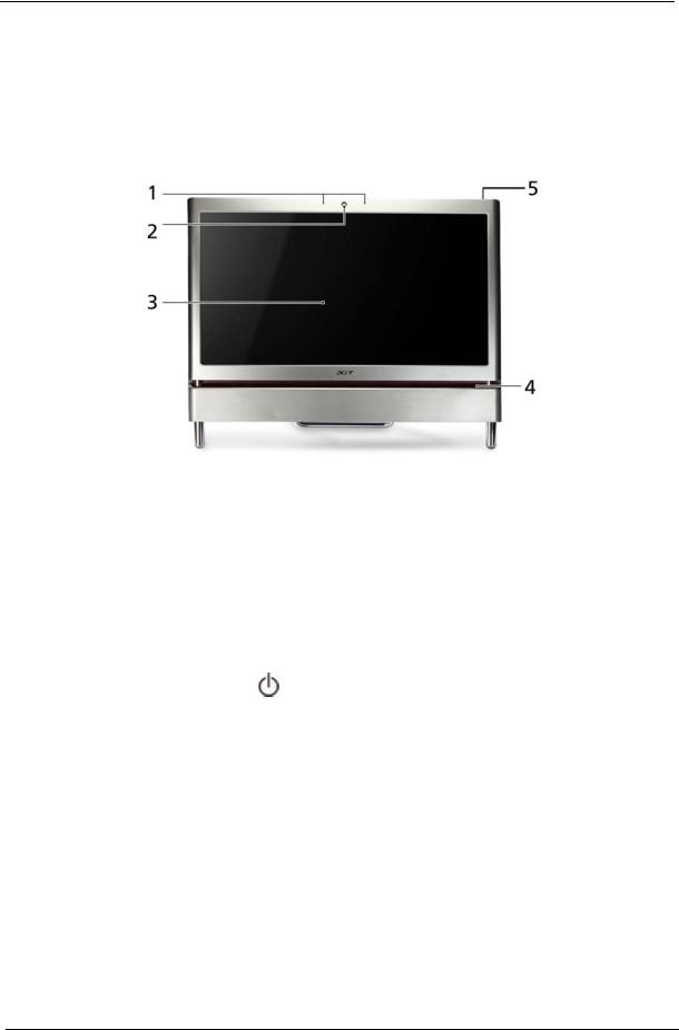
Front View
No. |
Component |
Icon |
Description |
|
|
|
|
1 |
Microphone |
|
Use to talk through when making Voice over |
|
|
|
Internet Protocol (VoIP) calls. |
|
|
|
|
2 |
HD webcam |
|
Use to let others see who they are communicating |
|
|
|
with when making VoIP calls. |
|
|
|
|
3 |
Display screen |
|
Also called Liquid-Crystal Display (LCD), displays |
|
|
|
computer output. |
4 |
Acer |
|
Access and control some of the handy features of |
|
TouchPortal |
|
your new computer. |
|
|
|
|
5 |
Power Button |
|
Press this button to turn the power on or off. |
|
|
|
You can also configure the power button to |
|
|
|
operate in Standby/Resume mode or |
|
|
|
Hibernate mode. |
|
|
|
|
4 |
Chapter 1 |
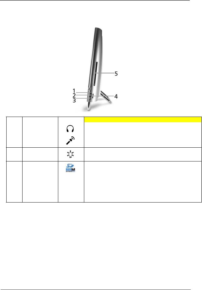
Right View
IMPORTANT:Your computer’s hardware options, port locations, and indicators may vary from this illustration.
No. |
Component |
Icon |
Description |
|
|
|
|
1 |
Headphone jack |
|
Plug powered, analog front speakers, an external amplifier, or |
|
(white plug) |
|
headphones into this jack. |
|
|
|
|
2 |
Microphone jack |
|
Plug a microphone into this jack. |
|
(pink plug) |
|
|
3Illumination Toggle Switch
4 |
Memory card |
Insert a memory card from a digital camera, MP3 player, PDA, |
|
reader |
cellular telephone, or other device into the memory card reader. |
|
|
|
5 |
Optical Disk Drive |
Use this drive to listen to audio CDs, install games and programs, |
|
|
watch DVDs, and |
|
|
store large files onto recordable discs (depending on drive type). This |
|
|
drive may be |
|
|
a CD, recordable CD, DVD, or recordable DVD. |
Chapter 1 |
5 |
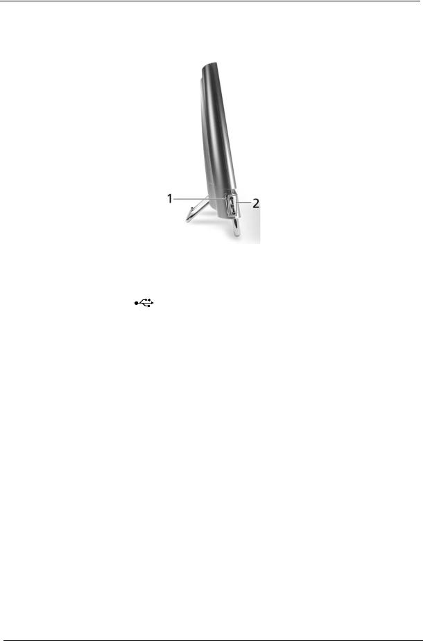
Left View
IMPORTANT:Your computer’s hardware options, port locations, and indicators may vary from this illustration.
No. |
Component |
Icon |
Description |
|
|
|
|
1 |
B-CAS reader |
|
Subscription service available for select models only. |
|
|
|
|
2 |
USB 2.0 port |
|
Plug USB (Universal Serial Bus) devices (such as a USB external |
|
|
|
drive, printer, scanner, camera, keyboard, or mouse) into this port. |
|
|
|
|
6 |
Chapter 1 |

Rear View
IMPORTANT:Your computer’s hardware options, port locations, and indicators may vary from this illustration.
No. |
Component |
Icon |
Description |
|
|
|
|
1 |
Power connector |
|
Plug the power cord into this connector. |
|
|
|
|
2 |
Kensington™ lock |
|
Secure your computer to an object by connecting a Kensington |
|
slot |
|
cable lock to this slot. |
|
|
|
|
3 |
USB ports |
|
Plug USB (Universal Serial Bus) devices (such as a USB printer, |
|
|
|
scanner, camera, keyboard, or mouse) into these ports. |
|
|
|
|
4 |
Ethernet (network) |
|
Plug an Ethernet network cable or a device (such as a DSL or |
|
jack |
|
cable modem for a broadband Internet connection) into this jack. |
|
|
|
|
5 |
Line-out/Speaker- |
|
Plug an line output to an amplifier or entertainment system into |
|
out jack |
|
this jack for sound output. |
|
|
|
|
6 |
eSATA port |
|
Plug external hard drives into this connector. |
|
|
|
|
7 |
TV Tuner |
|
Allows a TV Tuner to be connected to the system. |
|
|
|
|
8 |
IR port |
|
Allows data transfer between the desktop and a mobile device. |
|
|
|
|
Chapter 1 |
7 |
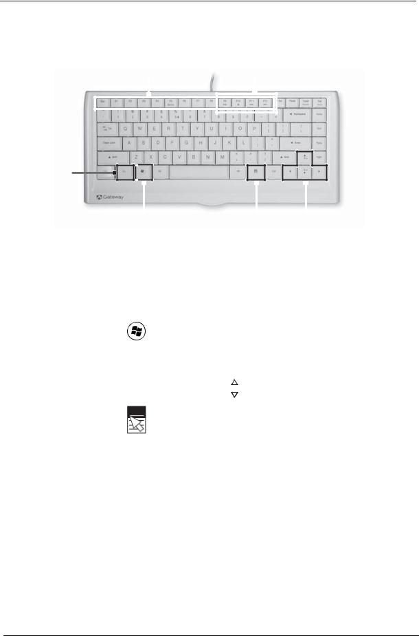
Using the Keyboard
The keyboard has several different types of keys and buttons as shown below.
Function keys |
Audio playback keys |
|
||||||||
|
|
|
|
|
|
|
|
|
|
|
|
|
|
|
|
|
|
|
|
|
|
|
|
|
|
|
|
|
|
|
|
|
|
|
|
|
|
|
|
|
|
|
|
|
|
|
|
|
|
|
|
|
|
|
|
|
|
|
|
|
|
|
|
|
|
Fn key
|
|
|
|
|
|
|
|
|
|
|
|
|
Windows key |
Application Navigation keys |
|||||||||
|
|
|
|
|
key |
||||||
|
|
|
|
|
|
|
|
|
|
|
|
Feature |
Icon |
|
|
|
Description |
||||||
|
|
|
|
|
|
|
|
|
|
|
|
Function keys |
|
|
|
|
Press these keys to start program actions. Each program uses |
||||||
|
|
|
|
|
different function keys for different purposes. See the program |
||||||
|
|
|
|
|
documentation to find out more about the function key actions. |
||||||
|
|
|
|
|
|
|
|
|
|
|
|
Audio playback keys |
|
|
|
|
Press these keys to play your audio files and to adjust the |
||||||
|
|
|
|
|
volume. |
||||||
Windows key |
|
|
|
|
Press this key to open the Windows Start menu. |
||||||
|
|
|
|
|
This key can also be used in combination with other keys to |
||||||
|
|
|
|
|
open utilities. See “Windows Keys” on page 9. |
||||||
Fn key |
|
|
|
|
Press this key in combination with keys that have alternate |
||||||
|
|
|
|
|
functions defined, such as the F9-F12 keys. |
||||||
|
|
|
|
|
Press <Fn> + < > to increase the brightness of the display. |
||||||
|
|
|
|
|
Press <Fn> + < > to decrease the brightness of the display. |
||||||
|
|
|
|
|
|
|
|
|
|
|
|
Application key |
|
|
|
|
Press this key to access shortcut menus and help assistants in |
||||||
|
|
|
|
|
Windows. |
||||||
|
|
|
|
|
|
|
|
|
|
|
|
Navigation keys |
|
|
|
|
Press these keys to move the cursor and to copy, cut, and |
||||||
|
|
|
|
|
paste objects. |
||||||
8 |
Chapter 1 |
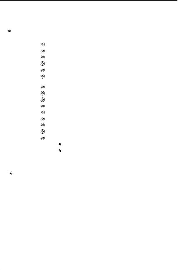
Windows Keys
The keyboard has two keys that perform Windows-specific functions.
|
|
|
Key |
Description |
|
|
|
|
|
|
|
|
Windows key |
Pressed alone, this key has the same effect as clicking on the Windows Start button; |
|
|
|
|
it launches the Start menu. It can also be used with other keys to provide a variety of |
|
|
|
|
functions: |
|
|
|
|
< >: Open or close the Start menu |
|
|
|
|
< > + <D>: Display the desktop |
|
|
|
|
< > + <E>: Open Windows Explore |
|
|
|
|
< > + <F>: Search for a file or folder |
|
|
|
|
< > + <G>: Cycle through Sidebar gadgets |
|
|
|
|
< > + <L>: Lock your computer (if you are connected to a network domain), or |
|
|
|
|
switch users (if you're not connected to a network domain) |
|
|
|
|
< > + <M>: Minimizes all windows |
|
|
|
|
< > + <R>: Open the Run dialog box |
|
|
|
|
< > + <T>: Cycle through programs on the taskbar |
|
|
|
|
< > + <U>: Open Ease of Access Center |
|
|
|
|
< > + <X>: Open Windows Mobility Center |
|
|
|
|
< > + <BREAK>: Display the System Properties dialog box |
|
|
|
|
< > + <SHIFT+M>: Restore minimized windows to the desktop |
|
|
|
|
< > + <TAB>: Cycle through programs on the taskbar by using Windows Flip 3-D |
|
|
|
|
< > + <SPACEBAR>: Bring all gadgets to the front and select Windows Sidebar |
|
|
|
|
<CTRL> + < > + <F>: Search for computers (if you are on a network) |
|
|
|
|
<CTRL> + < > + <TAB>: Use the arrow keys to cycle through programs on the |
|
|
|
|
taskbar by using Windows Flip 3-D |
|
|
|
|
Note: Depending on your edition of Windows 7, some shortcuts may not function as |
|
|
|
|
described. |
|
|
|
Application |
This key has the same effect as clicking the right mouse button; it opens the |
|
|
|
||
|
|
|
key |
application's context menu. |
|
|
|
||
|
|
|
|
|
Chapter 1 |
9 |

Hardware Specifications and Configurations
Processor
Item |
|
Specification |
|
|
|
CPU type |
• |
Intel Core™2 Quad Processor* |
|
• |
Intel Core™2 Duo Processor* |
|
• |
Intel Pentium Processor* |
|
• |
Intel® Celeron® processor* |
|
|
|
Core Logic |
• |
North Bridge (Eaglelake G45) |
|
• GTL+ interface (Front-side bus) |
|
|
|
• Support Intel Yorkfield/Wolfdale Processor |
|
|
• 800/1066/1333MHz transfer rate processor bus speed |
|
• |
Integrated DRAM controller |
|
|
• Dual-channel DDR3 SDRAM interface. |
|
|
• Unified Memory Architecture, with 128 MB to 256MB of |
|
|
the main memory configurable as display memory. |
|
|
• Asynchronous FSB and Memory Controller. |
|
|
• Supports Dual channel 800/1066 DDR3 SDRAM. |
|
|
• Max 8GB memory addressability, for faster system. |
|
• |
Serial ATA |
|
|
• Support maximum four SATA 3.0Gb/s ports.. |
|
• South Bridge (ICH10)PCI bus Interface |
|
|
|
• Supports PCI bus at 33MHz |
|
|
• PCI Rev.2.3 specification support. |
|
|
• Support for 64 bit addressing on PCI using DAC |
|
|
protocol.SMBus: SM Bus Rev.2.0 compliant. |
|
• |
Support Power management |
|
|
• ACPI Specification 3.0 compliant power management |
|
|
scheme. |
|
|
• ACPI-defined power states(C1, S1, S3, S4, S5 for |
|
|
Desktop) |
|
|
• ACPI-defined power states(C1~C4, S1, S3~S5 for Mobile) |
|
|
• ACPI Power Management Timer |
|
|
• SMI# generation |
|
• Low Pin Count(LPC) host interface |
|
|
• |
PCI Express Interface |
|
|
• Support PCI Express 1.1 |
|
|
• 6 PCI Express root ports |
|
|
• Support for full 2.5 Gb/s bandwidth in each direction per |
|
|
x1 lane |
|
|
|
CPU Package |
Flip-Chip Land Grid Array (FC-LGA8) technology |
|
|
|
|
CPU Core Voltage |
1.196 ±0.748 |
|
|
|
|
10 |
Chapter 1 |
Processor Specifications
Processor |
CPU |
Cores |
Bus |
Power |
Cache |
Package |
Acer P/N |
|
# |
Speed |
Speed |
Size |
|||||
|
|
|
|
|||||
|
|
|
|
|
|
|
|
|
E2220 |
2.4 GHz |
2 |
800 |
65 W |
1MB |
LGA |
KC.22201.DEM |
|
|
|
|
|
|
|
|
|
|
E5200 |
2.5 GHz |
2 |
800 |
65 W |
2MB |
LGA |
KC.52001.DEM |
|
|
|
|
|
|
|
|
|
|
E5300 |
2.6 GHz |
2 |
800 |
65 W |
2MB |
LGA |
KC.53001.DEM |
|
|
|
|
|
|
|
|
|
|
E5400 |
2.7 GHz |
2 |
800 |
65 W |
2MB |
LGA |
KC.54001.DEM |
|
|
|
|
|
|
|
|
|
|
E6300 |
2.8 GHz |
2 |
1066 |
65 W |
2 MB |
LGA |
KC.63001.DEM |
|
|
|
|
|
|
|
|
|
|
E6500 |
2.93 GHz |
2 |
1066 |
65 W |
2 MB |
LGA |
KC.65001.DEM |
|
|
|
|
|
|
|
|
|
|
E7300 |
2.66 GHz |
2 |
1066 |
65 W |
3 MB |
LGA |
KC.73001.DE0 |
|
|
|
|
|
|
|
|
|
|
E7400 |
2.8 GHz |
2 |
1066 |
65 W |
3 MB |
LGA |
KC.74001.DE0 |
|
|
|
|
|
|
|
|
|
|
E7500 |
2.93 GHz |
2 |
1066 |
65 W |
3 MB |
LGA |
KC.75001.DE0 |
|
|
|
|
|
|
|
|
|
|
E7600 |
3.06 GHz |
2 |
1066 |
65 W |
3 MB |
LGA |
KC.76001.DE0 |
|
|
|
|
|
|
|
|
|
|
Q8200s |
2.33 GHz |
4 |
1333 |
65 W |
4 MB |
LGA |
KC.82001.QQS |
|
|
|
|
|
|
|
|
|
|
E8400 |
3.0 GHz |
2 |
1333 |
65 W |
6 MB |
LGA |
KC.84001.DEE |
|
|
|
|
|
|
|
|
|
|
Q8400s |
2.66 GHz |
4 |
1333 |
65 W |
4 MB |
LGA |
KC.84001.QQS |
|
|
|
|
|
|
|
|
|
|
E8500 |
3.16 GHz |
2 |
1333 |
65 W |
6 MB |
LGA |
KC.85001.DEE |
|
|
|
|
|
|
|
|
|
|
E8600 |
3.33 GHz |
2 |
1333 |
65 W |
6 MB |
LGA |
KC.86001.DEE |
|
|
|
|
|
|
|
|
|
|
Q9400s |
2.66 GHz |
4 |
1333 |
65 W |
6 MB |
LGA |
KC.94001.QQS |
|
|
|
|
|
|
|
|
|
CPU Fan True Value Table
|
|
CPU Temperature |
|
|
|
||
|
Step |
FAN on |
|
FAN off |
CPU Fan RPM |
|
|
|
|
(°C) |
|
(°C) |
|
|
|
|
|
|
|
|
|
|
|
|
1 |
45 |
|
38 |
2100 |
|
|
|
2 |
50 |
|
46 |
2500 |
|
|
|
|
|
|
|
|
|
|
|
3 |
58 |
|
52 |
2800 |
|
|
|
|
|
|
|
|
|
|
|
4 |
64 |
|
59 |
3100 |
|
|
|
|
|
|
|
|
|
|
|
Throttling |
68 |
|
|
12 |
|
|
|
|
|
|
|
|
|
|
|
Shut Down |
75 |
|
|
12 |
|
|
|
|
|
|
|
|
|
|
|
|
|
|
|
|
|
|
|
|
VGA Temperature |
VGA Fan |
|
|
||
|
Step |
FAN on |
|
FAN off |
|
|
|
|
|
Voltage |
|
|
|||
|
|
(°C) |
|
(°C) |
|
|
|
|
|
|
|
|
|
||
|
|
|
|
|
|
|
|
|
1 |
44 |
|
38 |
2500 |
|
|
|
|
|
|
|
|
|
|
|
2 |
49 |
|
45 |
3000 |
|
|
|
|
|
|
|
|
|
|
|
3 |
55 |
|
50 |
3600 |
|
|
|
|
|
|
|
|
|
|
|
4 |
62 |
|
58 |
4000 |
|
|
|
|
|
|
|
|
|
|
|
Throttling |
90 |
|
|
12 |
|
|
|
|
|
|
|
|
|
|
|
Shut Down |
100 |
|
|
12 |
|
|
|
|
|
|
|
|
|
|
|
BIOS |
|
|
|
|
|
|
|
|
|
|
|
|
|
|
|
|
Item |
|
|
Specification |
|
|
|
|
|
|
|
|
|
|
|
BIOS vendor |
|
Phoenix BIOS |
|
|
|
|
|
|
|
|
|
|
|
|
|
BIOS Version |
|
R01-A1 |
|
|
|
|
|
|
|
|
||||
|
BIOS ROM type |
SPI interface to serial flash memory, SOP8 package |
|
||||
|
|
|
|
|
|
||
|
BIOS ROM size |
8 MB |
|
|
|
||
|
|
|
|
|
|
|
|
|
|
|
|
|
|
|
|
Chapter 1 |
11 |

Item |
|
Specification |
|
|
|
|
|
Supported protocols |
SMBIOS 2.4 |
|
|
BIOS password control |
Supervisor only |
|
|
|
|
|
|
System Memory |
|
|
|
|
|
|
|
Item |
|
Specification |
|
|
|
|
|
Memory controller |
Built in |
|
|
Memory size |
Non onboard |
|
|
|
|
|
|
DIMM socket number |
4 |
|
|
|
|
|
|
Supports memory size per socket |
2 GB |
|
|
|
|
|
|
Supports maximum memory size |
8 GB |
|
|
|
|
|
|
Supports DIMM type |
DDR3 SDRAM |
|
|
|
|
|
|
Supports DIMM Speed |
800/1066MHz |
|
|
|
|
|
|
Supports DIMM voltage |
1.5V |
|
|
|
|
|
|
Memory Combinations |
|
|
|
|
|
|
|
Slot 1 |
Slot 2 |
|
Total Memory |
|
|
|
|
0MB |
512MB |
|
512MB |
|
|
|
|
0MB |
1024MB |
|
1024MB |
|
|
|
|
0MB |
2048MB |
|
2048MB |
|
|
|
|
512MB |
512MB |
|
1024MB |
|
|
|
|
512MB |
1024MB |
|
1536MB |
|
|
|
|
512MB |
2048MB |
|
2560MB |
|
|
|
|
1024MB |
0MB |
|
1024MB |
|
|
|
|
1024MB |
512MB |
|
1536MB |
|
|
|
|
1024MB |
1024MB |
|
2048MB |
|
|
|
|
1024MB |
2048MB |
|
3072MB |
|
|
|
|
2048MB |
0MB |
|
2048MB |
|
|
|
|
2048MB |
512MB |
|
2560MB |
|
|
|
|
2048MB |
1024MB |
|
3072MB |
|
|
|
|
2048MB |
2048MB |
|
4096MB |
|
|
|
|
4096MB |
4096MB |
|
8192MB |
|
|
|
|
NOTE: Above table lists some system memory configurations. You may combine DIMMs with various capacities to form other combinations. On above table, the configuration of slot 1 and slot 2 could be reversed.
System Board Major Chips
Item |
Controller |
|
|
Core logic |
• EL8 implement Intel Yorkfield/Wolfdale Processor |
|
• Eaglelake G45 + ICH10 |
|
|
LAN |
RTL8111DL |
|
|
WLAN |
Support Mini PCIE , USB wireless LAN |
|
|
Audio Codec |
ALC888S |
|
|
Keyboard |
ITE8512-NX embedded |
|
|
12 |
Chapter 1 |

NorthBridge Chipset
Item |
|
|
|
Specification |
|
|
|
|
|
|
|
Chipset |
|
Eaglelake G45 |
|
||
Features |
|
• |
GTL+ interface (Front-side bus) |
|
|
|
|
• Support Intel Yorkfield/Wolfdale Processor |
|
||
|
|
• 800/1066/1333MHz transfer rate processor bus speed |
|
||
|
|
|
|
||
SouthBridge Chipset |
|
||||
|
|
|
|
|
|
Item |
|
|
|
Specification |
|
|
|
|
|
|
|
Chipset |
|
ICH10 |
|
||
|
|
|
|
|
|
Features |
|
• |
PCI bus Interface |
|
|
|
|
• Supports PCI bus at 33MHz |
|
||
|
|
• PCI Rev.2.3 specification support. |
|
||
|
|
• Support for 64 bit addressing on PCI using DAC protocol. |
|
||
|
|
|
|
|
|
Card Reader |
|
|
|
||
|
|
|
|
|
|
|
Item |
|
Specification |
|
|
|
|
|
|
|
|
Chipset |
|
|
|
JMB385 (SD, SDHC, MMC, MS, MS pro slot) |
|
Features |
|
|
|
• Compliant with PCI Express Base Spec. Revision 1.1 |
|
|
|
|
|
• Compliant with SD Spec. Part 1 Physical Layer Spec. Version 2.00 |
|
|
|
|
|
• Compliant with SD Spec. Part A2 SD Host Controller Standard Spec. |
|
|
|
|
|
Version 2.00 |
|
|
|
|
|
• Compliant with SD Spec. Part E1 SDIO Spec. Version 2.00 |
|
|
|
|
|
• Compliant with SD Spec. Part 2 File System Spec. Version 2.00 |
|
|
|
|
|
• Compliant with MultiMediaCard System Spec. Version 4.2 |
|
|
|
|
|
• Compliant with Memory Stick Standard Format Spec. Version 1.43-00 |
|
|
|
|
|
• Compliant with Memory Stick Standard Memory Stick PRO Format |
|
|
|
|
|
Spec. - without security spec. - Version 1.02-00 |
|
|
|
|
|
• Compliant with Memory Stick Pro-HG Duo Spec. Version 1.00 |
|
|
|
|
|
• Compliant with xD-Picture Card Spec. Version 1.20 |
|
|
|
|
|
• Compliant with xD-Picture Card Host Guideline Version 1.20 |
|
|
|
|
|
• Compliant with xD-Picture Card Format Spec. Version 1.11 |
|
|
|
|
|
|
|
USB 2.0 |
|
|
|
|
|
|
|
|
|
|
|
|
Item |
|
Specification |
|
|
|
|
|
|
|
|
Chipset |
|
|
|
SB ICH10 embedded |
|
Features |
|
|
|
• USB host interface with support for 12USB ports |
|
|
|
|
|
• 6 UHCI host controllers |
|
|
|
|
|
• 2 EHCI high-speed USB2.0 Host controller |
|
|
|
|
|
||
SATA Interface |
|
|
|
||
|
|
|
|
|
|
|
Item |
|
Specification |
|
|
|
|
|
|
|
|
Chipset |
|
|
|
ICH10 embedded |
|
Features |
|
|
|
• Fast SATA, 4 ports: |
|
|
|
|
|
• Support 3.5" HDD via SATA interface |
|
|
|
|
|
• Support SSD HDD via SATA interface |
|
|
|
|
|
• Support ODD via SATA interface |
|
|
|
|
|
• Support eSATA via SATA interface |
|
|
|
|
|
|
|
Chapter 1 |
13 |

USB
Item |
|
|
|
Specification |
|
|
|
|
|
|
|
Chipset |
|
ICH10 embedded |
|||
Features |
|
|
• |
Using 6 USB2.0 Ports for Base connector |
|
|
|
|
• |
Using 1 USB2.0 Port for PCIE/WLAN |
|
|
|
|
• |
Using 1 USB2.0 Port for PCIE/TV |
|
|
|
|
• |
Using 1 USB2.0 Port for Webcam |
|
|
|
|
• |
Using 1 USB2.0 Port for Bluetooth |
|
|
|
|
• |
Using 1 USB2.0 Port for Touch screen |
|
|
|
|
|
|
|
LAN Interface |
|
|
|
|
|
|
|
|
|
|
|
Item |
|
|
|
Specification |
|
|
|
|
|
||
LAN Chipset |
Realtek RTL8111DL |
||||
|
|
|
|
||
Supports LAN protocol |
10/100/1000M Fast Ethernet |
||||
|
|
|
|
|
|
LAN connector type |
RJ-45 |
|
|
||
|
|
|
|
|
|
LAN connector location |
Main Board |
|
|
||
|
|
|
|
|
|
Features |
• |
Integrated 10/100/1000N transceiver |
|||
|
• |
Auto-Negotiation with Next Page capability |
|||
|
• |
Supports PCI Express™ 1.1 |
|||
|
• |
Supports pair swap/polarity/skew correction |
|||
|
• |
Crossover Detection & Auto-Correction |
|||
|
• |
Wake-on-LAN and remote wake-up support |
|||
|
• |
Microsoft® NDIS5, NDIS6 Checksum Offload (IPv4, IPv6, TCP, UDP) and |
|||
|
|
Segmentation Task-offload (Large send v1 and Large send v2) support |
|||
|
• |
Supports Full Duplex flow control (IEEE 802.3x) |
|||
|
• |
Supports jumbo frame to 9K bytes |
|||
|
• |
Fully compliant with IEEE 802.3, IEEE 802.3u, IEEE 802.3ab |
|||
|
• |
Supports IEEE 802.1P Layer 2 Priority Encoding |
|||
|
• |
Supports IEEE 802.1Q VLAN tagging |
|||
|
• |
Embedded OTP memory can replace the external EEPROM |
|||
|
• |
Serial EEPROM |
|||
|
• |
Transmit/Receive on-chip buffer support |
|||
|
• |
Supports power down/link down power saving |
|||
|
• |
Built-in Switching regulator |
|||
|
• |
Supports PCI MSI (Message Signaled Interrupt) and MSI-X |
|||
|
• |
Supports quad core Receive-Side Scaling (RSS) |
|||
|
• |
Embeds an adaptive equalizer in PCI express PHY (PCB traces to reach 40 inches) |
|||
|
• |
Supports Deep Slumber Mode (DSM) power saving feature |
|||
|
• |
Customized LEDs |
|||
|
• |
64-pin QFN package (RTL8111D) and 48-pin LQFP (RTL8111DL) Green package |
|||
|
|
|
|
|
|
Audio Interface |
|
|
|
|
|
|
|
|
|
|
|
Item |
|
|
|
Specification |
|
|
|
|
|
|
|
Audio Controller |
|
|
ALC888S |
|
|
|
|
|
|
||
Audio onboard or optional |
|
Onboard |
|
||
|
|
|
|
|
|
Mono or Stereo |
|
|
Stereo |
|
|
|
|
|
|
|
|
Resolution |
|
|
Wide range (-80 dB ~ +42 dB) volume control with 1.5 dB resolution |
|
|
|
|
|
|
|
|
Compatibility |
|
|
EAX 1.0 and 2.0, Direct Sound 3D, I3DL2 |
|
|
|
|
|
|
|
|
14 |
Chapter 1 |

Item |
|
Specification |
|
|
|
Sampling Rate |
• |
DACs with 97dB SNR |
|
• ADCs with 90dB SNR |
|
|
• |
Internal Speaker(5WX2) |
|
• |
Line out 5.1 Channel |
|
• Head Phone out , MIC In , Digital MIC In |
|
|
• Software Sound Volume Control |
|
|
• Software Beep Volume control |
|
|
|
|
Internal Microphone |
Yes |
|
|
|
|
Chapter 1 |
15 |

16 |
Chapter 1 |

Chapter 2
System Utilities
BIOS Setup Utility
The BIOS Setup Utility is a hardware configuration program built into your computer’s BIOS (Basic Input/ Output System).
Your computer is already properly configured and optimized, and you do not need to run this utility. However, if you encounter configuration problems, you may need to run Setup. Please also refer to Chapter 4 Troubleshooting when problem arises.
To activate the BIOS Utility, press F2 during POST (when “Press <F2> to enter Setup” message is prompted on the bottom of screen).
Press <F12> during POST to enter multi-boot menu. In this menu, user can change boot device without entering BIOS SETUP Utility.
Navigating the BIOS Utility
There are six menu options: Information, Main, Advanced, Security, Boot, and Exit.
Follow these instructions:
•To choose a menu, use the left and right arrow keys.
•To choose an item, use the up and down arrow keys.
•To change the value of a parameter, press F5 or F6.
•A plus sign (+) indicates the item has sub-items. Press Enter to expand this item.
•Press Esc while you are in any of the menu options to go to the Exit menu.
•In any menu, you can load default settings by pressing F9. You can also press F10 to save any changes made and exit the BIOS Setup Utility.
NOTE: You can change the value of a parameter if it is enclosed in square brackets. Navigation keys for a particular menu are shown on the bottom of the screen. Help for parameters are found in the Item Specific Help part of the screen. Read this carefully when making changes to parameter values. Please note that system information is subject to different models.
Chapter 2 |
17 |

Information
The Information screen displays a summary of your computer hardware information.
|
|
|
|
PhoenixBIOS Setup Utility |
|
|
|
|
|
|
|||
|
Info |
Main |
Advanced |
Security PC Health Power |
Boot |
Exit |
|
|
|||||
|
|
|
|
|
|
|
|
|
|
|
|
||
|
Processor Type |
Pentium(R) Dual-Core CPU |
|
|
Item Specific Help |
|
|||||||
|
|
|
|
|
|
|
|||||||
|
|
|
|
|
|
|
|||||||
|
Processor Speed |
E5200 @ 2.50GHz |
|
|
|
All items on this menu |
|
||||||
|
2.50 GHz |
|
|
|
|
|
|||||||
|
|
|
|
|
|
|
|
|
|
cannot be modified in |
|
||
|
System Memory: |
2048 MB |
|
|
|
|
user mode. If any |
|
|||||
|
System Manufacturer: |
Acer |
|
|
|
|
|
items require changes, |
|
||||
|
Product Name: |
|
Aspire Z5610 |
|
|
|
|
please consult your |
|
||||
|
System Serial Number: |
|
|
|
|
|
|
system Supervisor. |
|
||||
|
System BIOS Version: |
P0.19 |
|
|
|
|
|
|
|
|
|
||
|
BIOS Release Date: |
08/26/2009 |
|
|
|
|
|
|
|
|
|||
|
Asset Tag Number: |
|
|
|
|
|
|
|
|
|
|
||
|
|
|
|
|
|
|
|
|
|
|
|
|
|
|
|
|
|
|
|
|
|
|
|
|
|
|
|
|
F1 |
Help |
Select |
Item |
-/+ |
Change |
Values |
F9 |
Setup |
Defaults |
|||
|
Esc Exit |
Select |
Menu |
Press |
EnterPress |
Enter |
F10 |
Save |
and Exit |
||||
NOTE: The system information is subject to different models.
Parameter |
Description |
|
|
Processor Type |
This field shows the system processor type. |
|
|
Processor Speed |
This field shows the speed of the processor. |
|
|
System Memory |
This field reports the memory size of the system. Memory size on this model is |
|
fixed to 2048 MB. |
|
|
System Manufacturer |
This field displays the manufacturer of this system. |
|
|
Product Name |
This field shows product name of the system. |
|
|
System Serial Number |
This field displays the serial number of this unit. |
|
|
System BIOS Version |
This field displays system BIOS version. |
|
|
BIOS Release Date |
This field displays the release date of the system BIOS. |
|
|
Asset Tag Number |
This field displays the asset tag number of the system. |
|
|
18 |
Chapter 2 |

Main
The Main screen allows the user to set the system time and date as well as enable and disable boot options.
|
|
|
|
|
|
|
PhoenixBIOS Setup Utility |
|
|
|
|
|
|
|
|
Info |
|
Main |
|
Advanced |
Security PC Health Power |
Boot |
Exit |
|
|
||||
|
|
|
|
|
|
|
|
|
|
|
|
|
||
|
System Date: |
|
|
[08/26/2009] |
|
|
Item Specific Help |
|
||||||
|
|
|
|
|
|
|
|
|
||||||
|
|
|
|
|
|
|
|
|
||||||
|
System Time: |
|
|
[10:10:30] |
|
|
|
<Tab>, <Shift+Tab>, or |
|
|||||
|
|
|
|
|
|
|
|
|
|
|
|
|||
|
SATA Port 1 |
|
|
[320GB SATA1] |
|
|
<Enter> selects field. |
|
||||||
|
SATA Port 2 |
|
|
[CD-ROM] |
|
|
|
|
|
|
|
|||
|
SATA Port 4 |
|
|
[None] |
|
|
|
|
|
|
|
|||
|
Quick Boot: |
|
|
[Enabled] |
|
|
|
|
|
|
|
|||
|
Quiet Boot: |
|
|
[Enabled] |
|
|
|
|
|
|
|
|||
|
Bootup Num-Lock: |
|
[On] |
|
|
|
|
|
|
|
||||
|
Boot Sector Virus Protection: [Disabled] |
|
|
|
|
|
|
|
||||||
|
Halt On: |
|
|
[All,But KeyBoard] |
|
|
|
|
|
|
||||
|
|
|
|
|
|
|
|
|
|
|
|
|
|
|
|
|
|
|
|
|
|
|
|
|
|
|
|
|
|
|
F1 |
Help |
Select |
Item |
-/ + |
Change Values |
F9 |
Setup |
Defaults |
|||||
|
Es c |
Exit |
Select |
Menu |
Press Ent er |
Press Ent er |
|
|
F1 0 |
Save |
and Exit |
|||
NOTE: The screen above is for your reference only. Actual values may differ.
The table below describes the parameters in this screen. Settings in boldface are the default parameter settings.
Parameter |
Description |
Format/Option |
|
|
|
System Date |
Sets the system date. |
Format MM/DD/YYYY |
|
NOTE: If a CMOS checksum error or CMOS battery |
(month/day/year) |
|
loss occurs, set date to Jan 01 2009. |
|
System Time |
Sets the system time. The hours are displayed with 24- |
Format: HH:MM:SS |
|
hour format. |
(hour:minute:second) |
|
NOTE: If a CMOS checksum error or CMOS battery |
|
|
loss occurs, set time to 12:00:00. |
|
|
|
|
SATA Port 1 |
This field displays SATA type. |
N/A |
|
|
|
SATA Port 2 |
This field displays SATA type. |
N/A |
|
|
|
SATA Port 4 |
This field displays SATA type. |
N/A |
|
|
|
Quick Boot |
Allows startup to skip certain tests while booting, |
Option: Enabled or |
|
decreasing the time needed to boot the system. |
Disabled |
|
|
|
Quiet Boot |
Allows startup to skip normal POST messages while |
Option: Enabled or |
|
booting, decreasing the time needed to boot the |
Disabled |
|
system. |
|
|
|
|
Bootup Num Lock |
Set Num-Lock to on or off automatically during boot. |
Option: Off or On |
|
|
|
Boot Sector VIrus |
Write protects the Boot Sector. |
Option: Enabled or |
Protection |
|
Disabled |
|
|
|
Halt On |
Prompts the user when errors occur during boot up |
Option: All Errors, No |
|
process. |
Errors, All, But KeyBoard |
|
NOTE: Selecting All, But KeyBoard halts the system |
|
|
for all errors excluding keyboard errors. |
|
|
|
|
Chapter 2 |
19 |

SATA Port 1
The SATA Port 1 screen allows the user to view and adjust SATA settings on Port 1.
|
|
|
|
|
|
PhoenixBIOS Setup Utility |
|
|
|
|
|
|
||
|
Info |
|
Main |
Advanced |
Security PC Health Power |
Boot |
Exit |
|
|
|||||
|
|
|
|
|
|
|
|
|
|
|
|
|
||
|
|
|
SATA Port 1 |
|
[320GB SATA1] |
|
|
|
Item Specific Help |
|
||||
|
Type: |
|
|
[Auto] |
|
|
|
|
|
|
|
|
||
|
|
|
|
|
|
|
User = you enter |
|
||||||
|
|
|
|
|
|
|
|
|
|
|
|
|||
|
Multi-Sector Transfers: |
|
[16 Sectors] |
|
|
|
parameters of hard-disk |
|
||||||
|
LBA Mode Control: |
|
[Enabled] |
|
|
|
drive installed at this |
|
||||||
|
32 BIT Data Transfer: |
|
[Disabled] |
|
|
|
connection. |
|
|
|||||
|
S.M.A.R.T.: |
|
|
Auto |
|
|
|
|
Auto = autotypes |
|
||||
|
|
|
|
|
|
|
|
|
|
|
hard-disk drive |
|
||
|
|
|
|
|
|
|
|
|
|
|
installed here. |
|
|
|
|
|
|
|
|
|
|
|
|
|
|
CD-ROM = a CD-ROM drive |
|
||
|
|
|
|
|
|
|
|
|
|
|
is installed here. |
|
||
|
|
|
|
|
|
|
|
|
|
|
ATAPI Removable = |
|
||
|
|
|
|
|
|
|
|
|
|
|
removable disk drive is |
|
||
|
|
|
|
|
|
|
|
|
|
|
installed here. |
|
|
|
|
|
|
|
|
|
|
|
|
|
|
|
|
|
|
|
|
|
|
|
|
|
|
|
|
|
|
|
|
|
|
F1 |
Help |
Select |
Item |
-/+ |
Change |
Values |
F9 |
Setup |
Defaults |
||||
|
Esc Exit |
Select |
Menu |
Press |
EnterPress |
Enter |
F10 |
Save |
and Exit |
|||||
NOTE: The screen above is for your reference only. Actual values may differ.
The table below describes the parameters in this screen. Settings in boldface are the default parameter settingsT
Parameter |
Description |
Format/Option |
|
|
|
Type |
The system automatically detects SATA type. |
N/A |
|
|
|
Multi Sector |
Allows the system IDE controller to transfer multiple |
N/A |
Transfers |
sectors per interuppt. |
|
|
|
|
LBA Mode Control |
The system enables LBA Mode Control by default. |
N/A |
|
|
|
32Bit Data Transfer |
Allows the system 32-bit access to maximize the IDE |
Option: Disabled or |
|
hard disk data transfer rate. |
Enabled |
S.M.A.R.T. |
The system automatically monitors hard disks for |
N/A |
|
indicators of reliability in order to anticipate failures. |
|
|
|
|
20 |
Chapter 2 |
Loading...