

Page 1

Acer
WLAN 11g Broadband Router
User Manual
Page 2

This product is in compliance with the essential
requirements and other relevant provisions of the
R&TTE directive 1999/5/EC.
Product Name: Acer WLAN 11g Broadband Router
Model Name : WLAN-G-RU2
MAX. OUT POWER
Spain
France
France
Italy
UK
Netherlands
Germany
Austria
Belgium
Switzerland
Luxemburg
Ireland
Portugal
Norway
Denmark
Finland
Iceland
Greece
Lichtenstein
Sweden
COUNTRY CHANNELS
2400-2483.5 MHz 1-13 < 100 mW EIRP < 100 mW EIRP
2400-2454 MHz 1-8 < 100 mW EIRP < 100 mW EIRP
2454-2483.5 MHz 9-13 < 100 mW EIRP < 10 mW EIRP
2400-2483.5 MHz 1-13 < 100 mW EIRP < 100 mW EIRP
2400-2483.5 MHz 1-13 < 100 mW EIRP < 100 mW EIRP
2400-2483.5 MHz 1-13 < 100 mW EIRP < 100 mW EIRP
2400-2483.5 MHz 1-13 < 100 mW EIRP < 100 mW EIRP
2400-2483.5 MHz 1-13 < 100 mW EIRP < 100 mW EIRP
2400-2483.5 MHz 1-13 < 100 mW EIRP < 100 mW EIRP
2400-2483.5 MHz 1-13 < 100 mW EIRP < 100 mW EIRP
2400-2483.5 MHz 1-13 < 100 mW EIRP < 100 mW EIRP
2400-2483.5 MHz 1-13 < 100 mW EIRP < 100 mW EIRP
2400-2483.5 MHz 1-13 < 100 mW EIRP < 100 mW EIRP
2400-2483.5 MHz 1-13 < 100 mW EIRP < 100 mW EIRP
2400-2483.5 MHz 1-13 < 100 mW EIRP < 100 mW EIRP
2400-2483.5 MHz 1-13 < 100 mW EIRP < 100 mW EIRP
2400-2483.5 MHz 1-13 < 100 mW EIRP < 100 mW EIRP
2400-2483.5 MHz 1-13 < 100 mW EIRP < 100 mW EIRP
2400-2483.5 MHz 1-13 < 100 mW EIRP < 100 mW EIRP
2400-2483.5 MHz 1-13 < 100 mW EIRP < 100 mW EIRP
INDOOR OUTDOOR
Page 3

Copyright
Copyright 2004 by Acer Inc., All rights reserved. No part of this publication may
be reproduced, transmitted, transcribed, stored in a retrieval system, or
translated into any language or computer language, in any form or by any
means, electronic, mechanical, magnetic, optical, chemical, manual or
otherwise, without the prior written permission of Acer Computer GmbH
Disclaimer
Acer Inc. makes no representations or warranties, either expressed or implied,
with respect to the contents hereof and specifically disclaims any warranties,
merchantability or fitness for any particular purpose. Any software described in
this manual is sold or licensed "as is". Should the programs prove defective
following their purchase, the buyer (and not this company, its distributor, or its
dealer) assumes the entire cost of all necessary servicing, repair, and any
incidental or consequential damages resulting from any defect in the software.
Further, Acer Computer GmbH, reserves the right to revise this publication and
to make changes from time to time in the contents hereof without obligation to
notify any person of such revision or change.
All brand and product names mentioned in this manual are trademarks and/or
registered trademarks of their respective holders
.
Page 4

Contents
1. OVERVIEW ................................................................................................................. 3
1.1 Product Feature................................................................................................... 3
1.2 System Requirements ......................................................................................... 3
1.3 Applications........................................................................................................ 3
2. Installing Your Router .................................................................................................. 1
2.1 Installation Instructions ...................................................................................... 1
3. Preparing Your Network............................................................................................... 2
3.1 Configuring Windows for IP Networking .......................................................... 2
3.2 To Configure Windows to Receive Dynamic IP Address:.................................. 2
3.3 Collecting ISP Information................................................................................. 4
4. Basic Functions ............................................................................................................ 5
4.1 To Open the Web-based Administration Tool:.................................................... 5
4.2 Setup................................................................................................................... 7
4.3 Global Address ..................................................................................................11
4.4. Wireless ........................................................................................................... 14
4.5 Tools ................................................................................................................. 23
4.6 Status ................................................................................................................ 27
4.7 DHCP ............................................................................................................... 30
4.8 Log.................................................................................................................... 32
4.9 Statistics............................................................................................................ 35
5. Advanced Function ..................................................................................................... 36
5.1. To Toggle between Basic Functions and Advanced Functions: ...................... 36
5.2 Virtual Servers .................................................................................................. 37
5.3 Filters................................................................................................................ 40
5.4 IP/URL Block................................................................................................... 44
5.5 Special Apps ..................................................................................................... 47
5.6 DMZ Host......................................................................................................... 51
5.7 MAC Clone ...................................................................................................... 53
5.8 Dynamic DNS .................................................................................................. 54
5.9 Proxy DNS........................................................................................................ 56
5.10 SNMP ............................................................................................................. 58
5.11 Static Routing ................................................................................................. 61
2
Page 5

1. OVERVIEW
1.1 Product Feature
▪ Compliance with IEEE 802.11g and 802.11b standards
▪ Highly efficient design mechanism to provide unbeatable performance
▪ Strong network security with WEP and 802.1X encryption
▪ Achieving data rate up to 54Mbps for 802.11g and 11Mbps for 802.11b with wide
range coverage; high performance to deliver up to 54Mbps raw data rate for 802.11g
▪ Quick and easy setup with Web-based management utility
1.2 System Requirements
▪ Windows 98, 98SE, Millennium Edition (ME), 2000 and XP operating
systems
▪ Microsoft Internet Explorer 5.5 or higher
▪ DSL/ Cable Modem Broadband Internet connection and ISP account
▪ PCs equipped with 10 Mbps or 10/100 Mbps Ethernet connection to support TCP/IP
protocol
▪ One CD-ROM driver
1.3 Applications
▪ Home SOHO networking for device sharing and wireless multimedia
▪ Wireless office provides a wider range for home and SOHO Ethernet
▪ Enables wireless building-to-building data communication
▪ Built-in infrastructure mode
▪ Router provides ideal solution for:
Temporary LANs for scenarios such as trade-exhibitions and meetings
Enables LAN adaptability to frequently changing environments
Enables remote access to corporate network information, for example e-mail and
company home page
3
Page 6

2. Installing Your Router
In this chapter, you’ll learn how to connect your router.
2.1 Installation Instructions
To Connect the Router:
2.1.1. Make sure all equipments are turned off, including the router, Desktop or
Laptop PCs, the cable and DSL modem, and so on.
2.1.2. Connect the WAN Port of the router to the cable and DSL modem,
Ethernet Server or the hub.
2.1.3. Connect your client PCs to the LAN Ports.
2.1.4. Connect the Power Adaptor (5VDC, 1.2A) to the power jack of the router
and plug the power cable into the outlet.
2.1.5. Turn on our PCs.
Page 7
3. Preparing Your Network
In this chapter, you’ll learn what to do before configuring your
network.
Before configuring your router, you need set up the computers in
your network for TCP/IP networking and collect relevant ISP
information if necessary.
3.1 Configuring Windows for IP Networking
Each computer in your network should be configured for TCP/IP
networking. There are two ways to configure your computers:
▪ You are commended to use DHCP, then you can simply choose
to receive an IP address automatically. For detailed instructions,
see Configure Windows to Receive Dynamic IP Address
.
▪ If you don’t use DHCP, you need assign an IP address to each
computer manually. For detailed instructions, refer to your
Windows Documentation.
3.2 To Configure Windows to Receive Dynamic IP
Address:
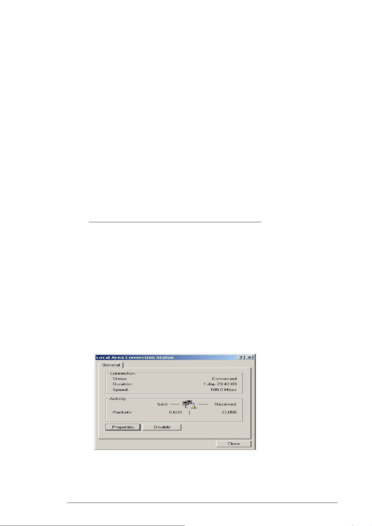
3.2.1. Click Start, then choose Settings > Network and Dial-up
Connections.
3.2.2. Select the name of your ISP connection.
FIGURE 3-1:
The Local Area Connection Status dialog box appears, seen in
FIGURE 3-1: Local Area Connection Status dialog box
3.2.3. Click Properties.
2
Page 8
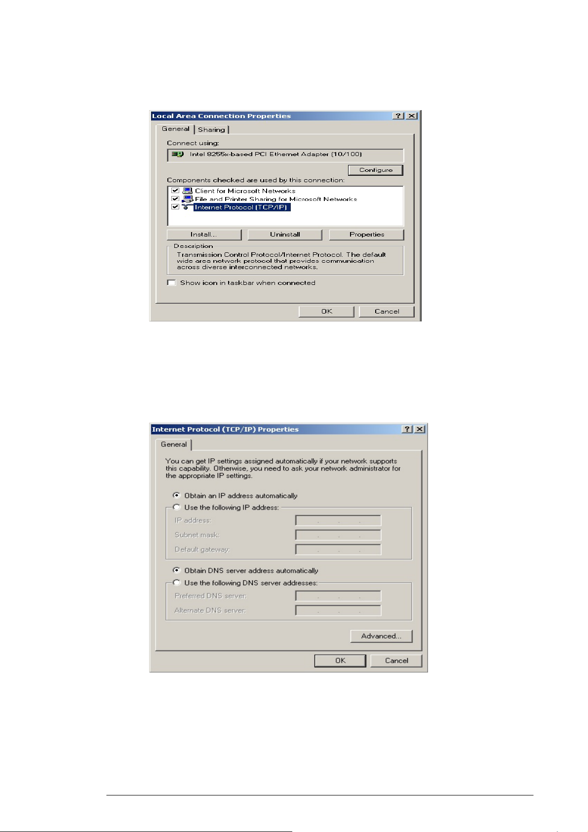
The Local Area Connection Properties dialog box appears, seen
in FIGURE 3-2:
FIGURE 3-2: Local Area Connection Properties dialog box.
3.2.4. Click Internet Protocol (TCP/IP), then click Properties.
The Internet protocol (TCP/IP) Properties dialog box appears,
seen in FIGURE 3-3:
FIGURE 3-3: Internet Protocol (TCP/IP) Properties dialog box
3.2.5. Click Obtain an IP address automatically and Obtain DNS server
address automatically.
3.2.6. Click OK.
3
Page 9

You need restart your computer now or at a later time.
Note :
The procedural steps above apply to Windows 2000 only. For Windows
95/98/ME/NT/XP, refer to your Windows Documentation.
3.3 Collecting ISP Information
You need query the relevant information from your ISP before
configuring your router, for example:
▪ Has your ISP assigned you a static or dynamic IP address? If
you have obtained one static IP address, what is it?
▪ Does your ISP use PPPoE? If so, what is your PPPoE user name
and password?
If you are not sure of the above questions, call your ISP to clarify them.
4
Page 10
4. Basic Functions
In this chapter, you will learn how to use basic functions that the
Company AP Router provides, including Setup, Global Address,
Wireless Tools, Status, DHCP, Log and Printer.
The Acer WLAN 11g Broadband Router provides you a Web-based
Administration Tool with which you can easily set up the router and
customize the basic router settings. You can use this Web-based
Tool from any computer in your network.
Notes :
Microsoft Internet Explorer 5.0 or later is highly recommended for
using this Web-based Tool.
Graphics sampled in this chapter are provided for illustrations only.
They may slightly differ from your own router screens.
4.1 To Open the Web-based Administration Tool:
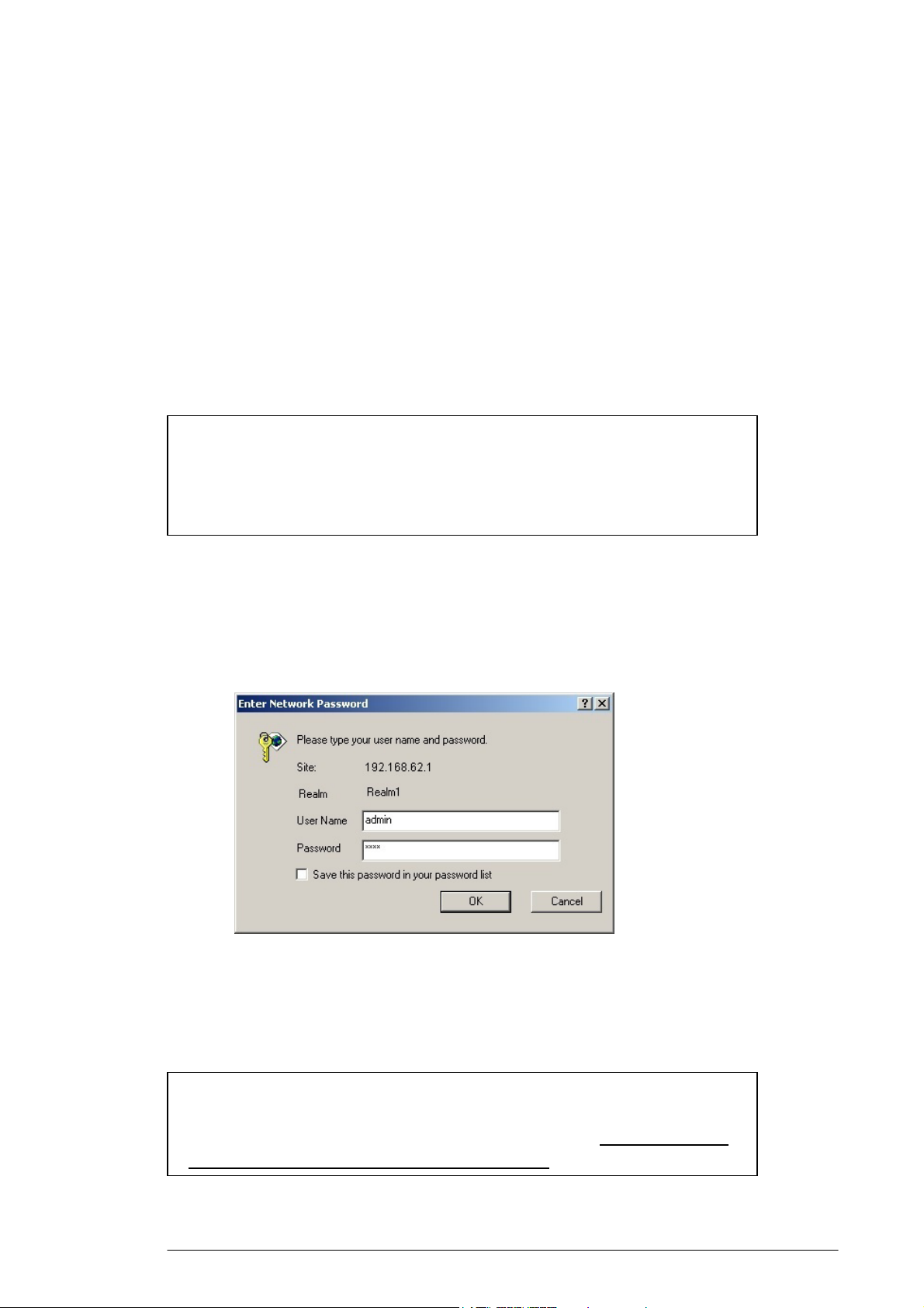
4.1.1. Open the browser on your PC.
4.1.2. Type http://192.168.62.1 in the Address bar.
The Logon dialog box appears, seen in FIGURE 4-1:
FIGURE 4-1: Logon dialog box
4.1.3. Type admin in the User Name box.
4.1.4. Type the password in the box.
Note :
The default password is “1234”. You can change the password
on the Tools page. For detailed instructions, see To Change the
Administrative Password for Your Router.
5
Page 11

4.1.5. Optional. To log on to the Administration Tool once for all, select
the check box of Save this password in your password list.
4.1.6. Click OK.
Note :
The Administration Tool will time out after a period of idling, the
Router may ask you to log on again.
The Company AP Router Administration Tool appears.
6
Page 12
4.2 Setup
The Setup page allows you to edit the basic configuration
parameters for your router, such as Host Name, Domain Name, LAN
IP Address, WAN IP Address, PPPoE Login, UPNP, and so on.
In most cases, the default settings will be Okay for you. However,
different ISPs (Internet Service Provider) may ask for specific
requirements, please check it with your ISP if you are not sure.
4.2.1. To Configure Setup Parameters:
4.2.1.1. Click Setup on the navigation bar.
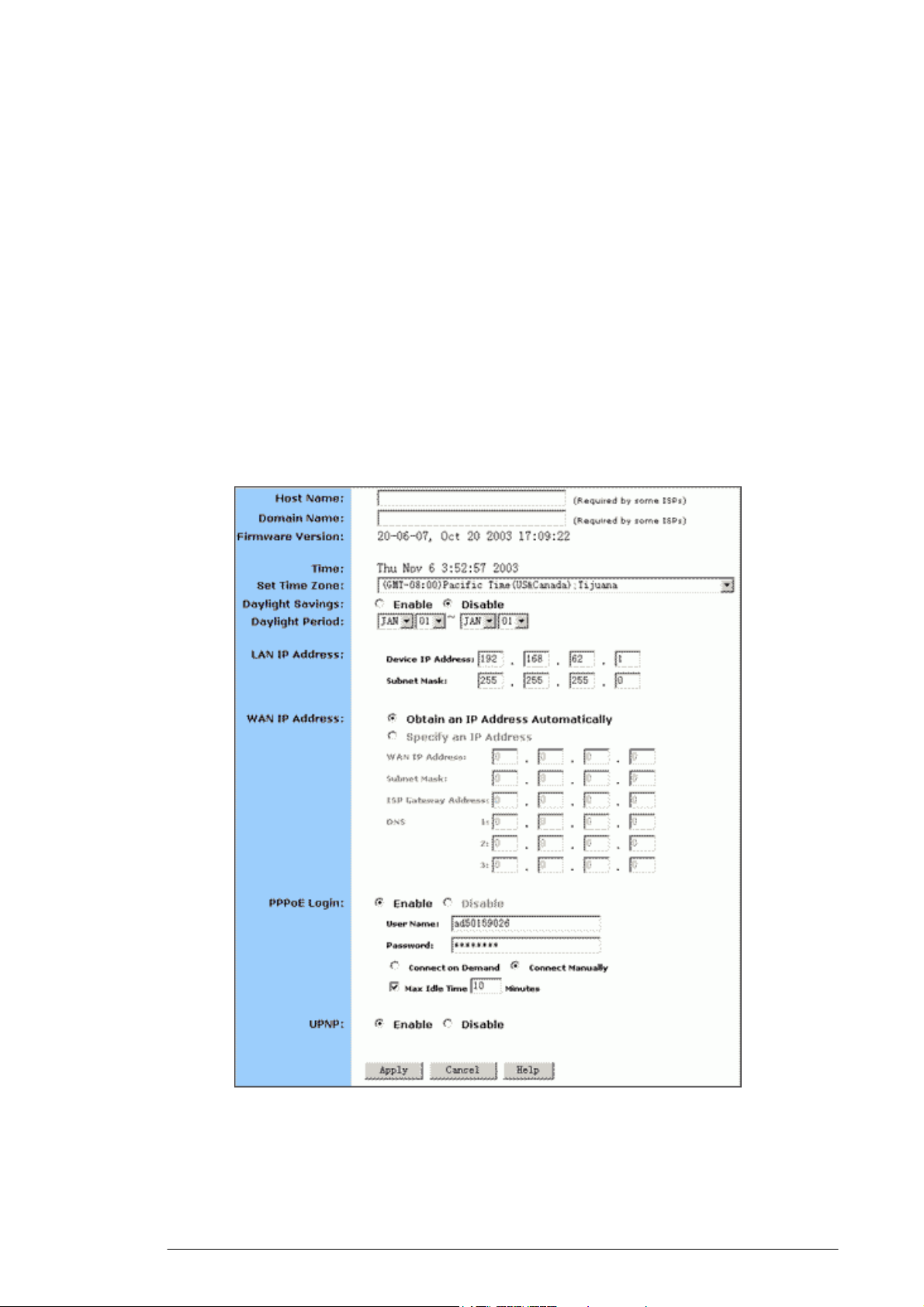
The Setup page appears, seen in FIGURE 4-2:
FIGURE 4-2: Setup page
4.2.1.2. Type the Host Name, System Name or Account Name in the
Host Name box if your ISP requires.
7
Page 13
y
y
4.2.1.3. Type the Domain Name of your ISP in the box if your ISP
requires, such as xyz.isp.com.
4.2.1.4. Optional. Review the firmware version number and date
information that you are currently using.
4.2.1.5. Select a specific Time Zone from the Set Time Zone drop-down
list, such as (GMT+08:00) Beijing, Chongqing, Hong Kong,
Urumqi.
4.2.1.6. If you want to use Daylight Savings time, click Enable and
select the start date and end date from the Daylight Period
drop-down lists.
4.2.1.7. If you don’t want to use Daylight Savings time, click Disable. If
you select to disable the Daylight Savings, Daylight Period will
not take effect any more.
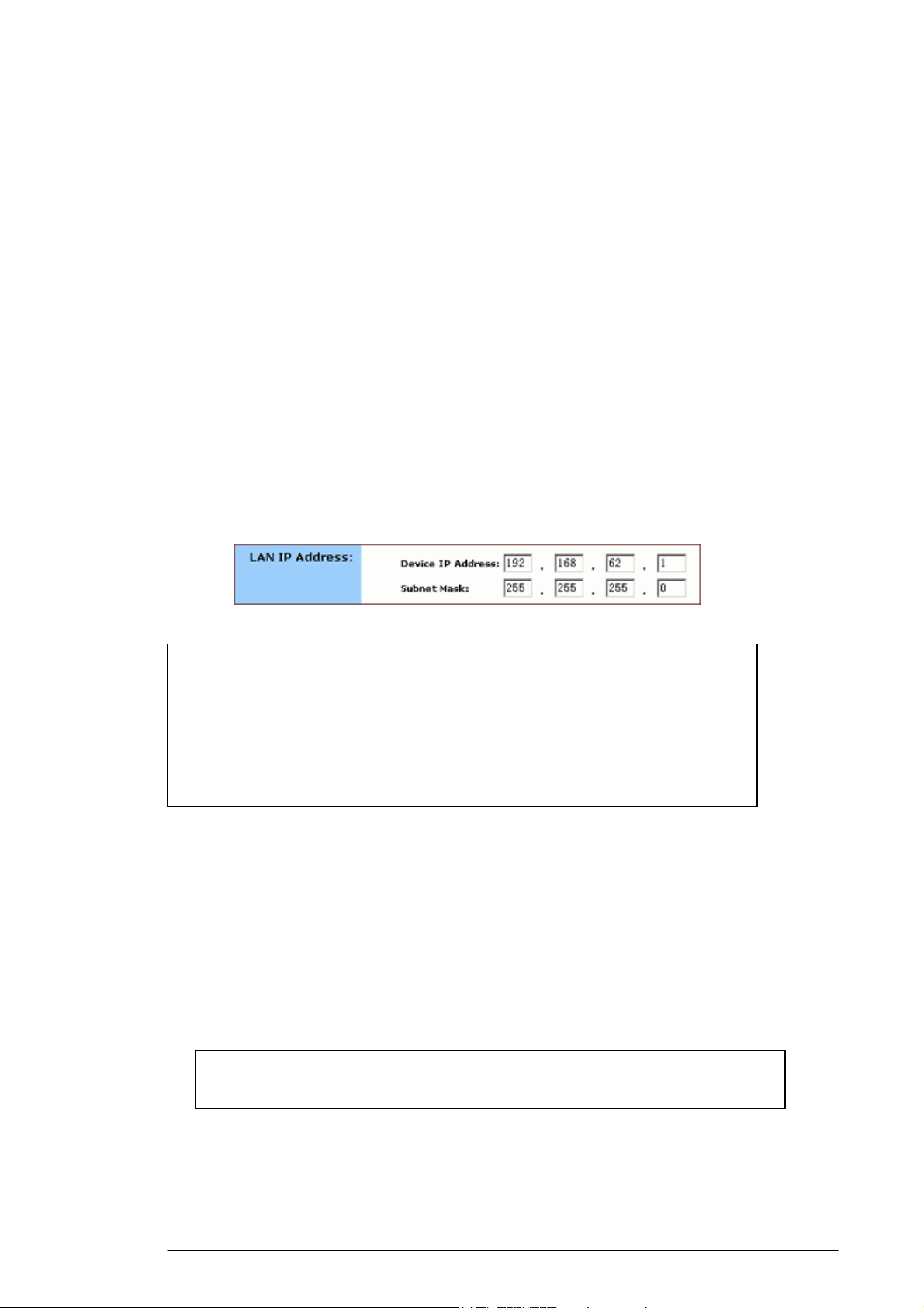
4.2.1.8. Optional. Review the Device IP Address and Subnet Mask next
to LAN IP Address and change the information if necessary.
Notes :
Device IP Address and Subnet Mask are invisible to users on the LAN
(Local Area Network) only.
In most cases, you need not make any change to LAN IP Address. If
you change the LAN IP Address with DHCP enabled, you need to
restart your client PCs; otherwise, you need reconfigure your client’s
IP addresses manuall
.
4.2.1.9. If you have enabled the DMZ feature on the DHCP page, review
the DMZ IP Address and Subnet Address next to DMZ IP
Address and change the information if necessary.
4.2.1.10. For WAN IP Address (Wide Area Network, also called Public
IP), choose either Obtain an IP Address automatically or
Specify an IP Address if your ISP has assigned you with static
IP).
Note :
ou choose to obtain an IP Address automatically, skip Step
If
4.2.1.11. Optional. If you select Specify an IP Address, type the WAN
IP Address, Subnet Mask, ISP Gateway Address and DNS in
8
Page 14
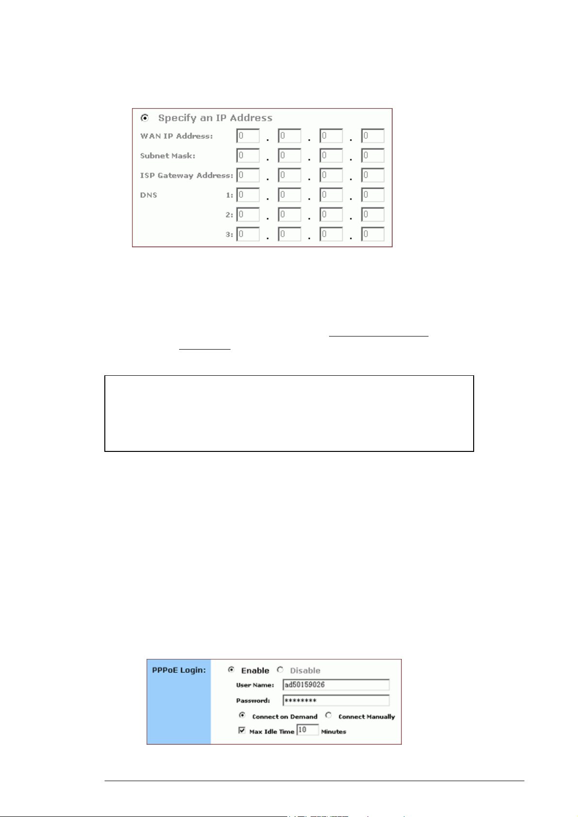
the boxes, seen in FIGURE 4-3. You can collect such
information from your ISP.
FIGURE 4-3: WAN IP Address - Specify an IP Address
4.2.1.12. If your ISP uses PPPoE (Point to Point Protocol over Ethernet),
click Enable next to PPPoE Login; otherwise, click Disable.
For detailed instructions on how to set the PPPoE Login
parameters in FIGURE 3-4, see To Set PPPoE Login
Parameters below.
Notes :
Using PPPoE, your ISP can authenticate your connection with a
specific user name and password for security issues.
If you enable PPPoE, make sure to uninstall all existing applications
on any computer in your network.
4.2.113. If you want to use UPNP (Universal Plug and Play) to plug
devices like PCs, routers and others into a network and to
automatically know about each other, click Enable next to
UPNP; otherwise, click Disable.
4.2.1.14. When you have completed all the settings, click Apply, or click
Cancel to undo your changes.
4.2.2. To Set PPPoE Login Parameters:
4.2.2.1. Click Enable next to PPPoE Login.
FIGURE 4-4: Set PPPoE Login Parameters
9
Page 15

4.2.2.2. Type the User Name and Password provided by your ISP.
4.2.2.3. For connection types, you can select either Connect on Demand
or Connect Manually.
4.2.2.4. Optional. If you want to limit the idling minutes, select Max Idle
Time and type a maximum number in minutes.
10
Page 16
4.3 Global Address
On the Global Address page, you can set up NAT (Network Address
Translation) to provide internal-to-external IP address mappings.
Notes :
If you want to use Global Address mapping, you must enable
NAT on the Filters page. For detailed instructions, see To Set up a
Port Filtering or Raw IP Filter.
If you have chosen to retrieve an IP address automatically, you
will not need to use this function. Instead, the default public IP
address will display on the Global Address page.
Have you enabled DMZ on the DHCP page? Depending on whether DMZ
is enabled, you may follow different procedural steps.
What do you want to do?
▪ Set up Global Address with DMZ Disabled
▪ Set up Global Address with DMZ Enabled
▪ Remove Global Addresses
4.3.1. To Set up Global Address with DMZ Disabled:
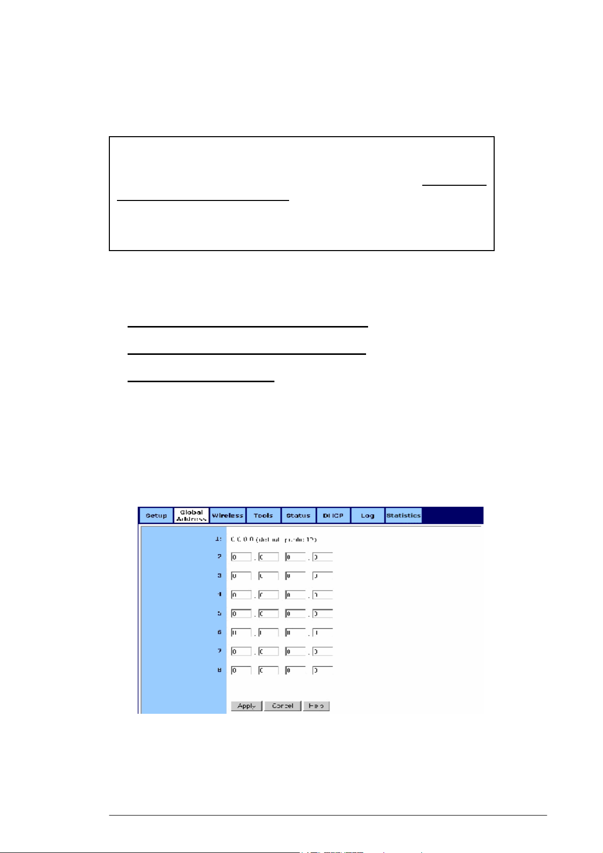
4.3.1.1. Click Global Address on the navigation bar.
The Global Address page with DMZ Disabled appears, seen in
FIGURE 4-5:
FIGURE 4-5: Global Address Page with DMZ Disabled
4.3.1.2. Review the first line in the above figure. It shows the default
WAN IP address which is specified on the Setup page. If your
11
Page 17
ISP assigns you an IP address automatically, it will display
here.
4.3.1.3. In Line 2 – Line 8, you can list up to 7 additional static, external
IP addresses provided by your ISP.
4.3.1.4. When you have completed editing all the settings, click Apply,
or click Cancel to undo your changes.
4.3.2. To Set up Global Address with DMZ Enabled:
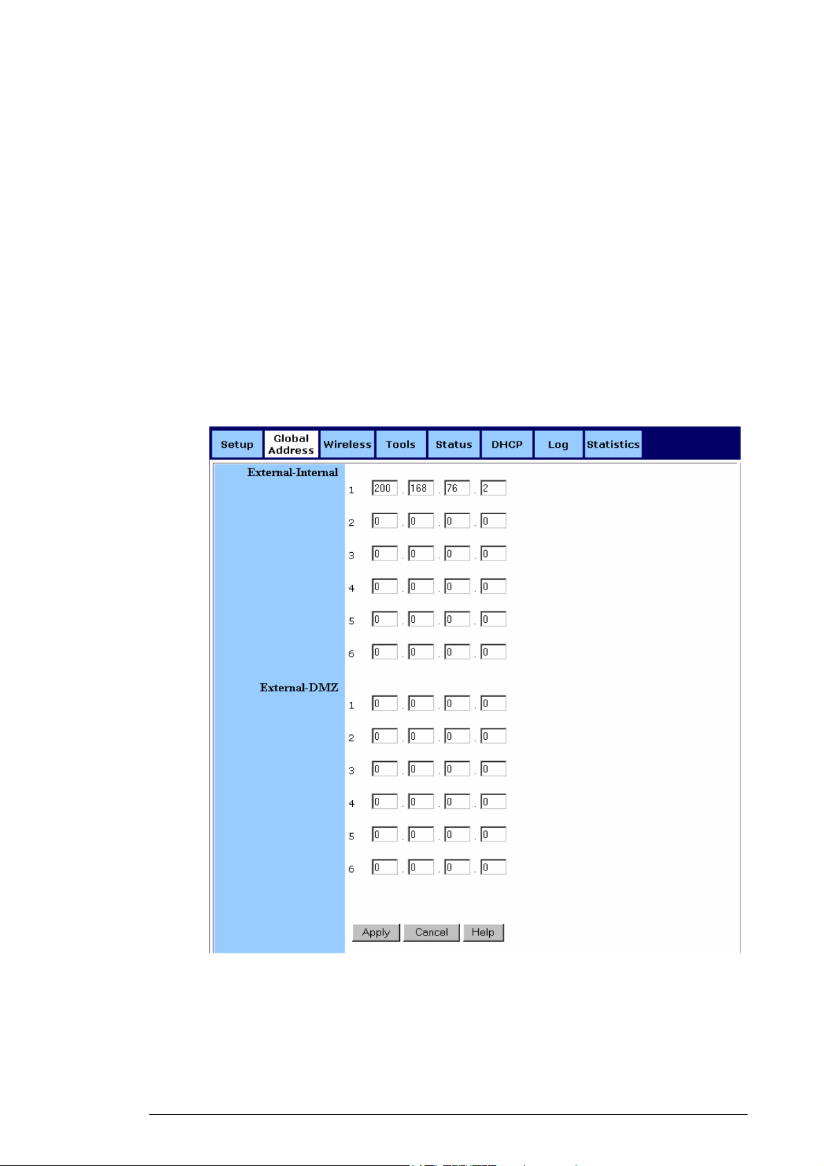
4.3.2.1. Click Global Address on the navigation bar.
The Global Address page with DMZ Enabled appears, seen in
FIGURE 4-6:
FIGURE 4-6: Global Address Page with DMZ Enabled
4.3.2.2. Review the first line in the above figure. It shows the default
WAN IP address which is specified on the Setup page. If your
ISP assigns you an IP address automatically, it will display
here.
12
Page 18

4.3.2.3. Next to External - Internal, you can list up to 6 static, external IP
addresses provided by your ISP.
4.3.2.4. Next to External – DMZ, define for your DMZ network up to 6
static, external global IP addresses provided by your ISP.
4.3.2.5. When you have completed editing all the settings, click Apply,
or click Cancel to undo your changes.
4.3.3. To Remove Global Addresses:
4.3.3.1. Click Global Address on the navigation bar.
4.3.3.2. For any entry you want to delete, enter 0.0.0.0, and click Apply.
13
Page 19

4.4. Wireless
Using Wireless, you can configure your router for wireless access.
There are three parts on the Wireless page:
▪ Radio Settings: Allows you to configure your Gateway for
wireless access, including Wireless Enable/Disable, Mode, ESSID,
Beacon Interval, RTS Threshold, Preamble Type, Distribution
System, and so on.
▪ Security Setting: Allows you to configure your Gateway for
security issues.
▪ Status: Allows you to find out your Gateway’s AP Radio
statistics and wireless devices of which the AP (Access Point) is
aware.
You can easily toggle between the above three parts on the Wireless
page.
On the Radio Settings page, Wireless Distribution System as defined
by the IEEE 802.11 standard has been made available on the
Company AP Router now. Hence, it is possible to wirelessly connect
Access Points using up to 8 MAC Addresses of PC cards, so that you
can extend a wired infrastructure to locations where cabling is not
available. Thus those users can roam or stay connected to the
available network resources.
What do you want to do?
▪ Set the Wireless Radio Parameters
▪ Set the Wireless Security Parameters
▪ Review Wireless Status
▪ Disable Wireless
4.4.1. To Set the Wireless Radio Parameters:
4.4.1.1. On the Wireless page, select Radio Settings.
The Radio Settings page appears, seen in FIGURE 4-7:
14
Page 20
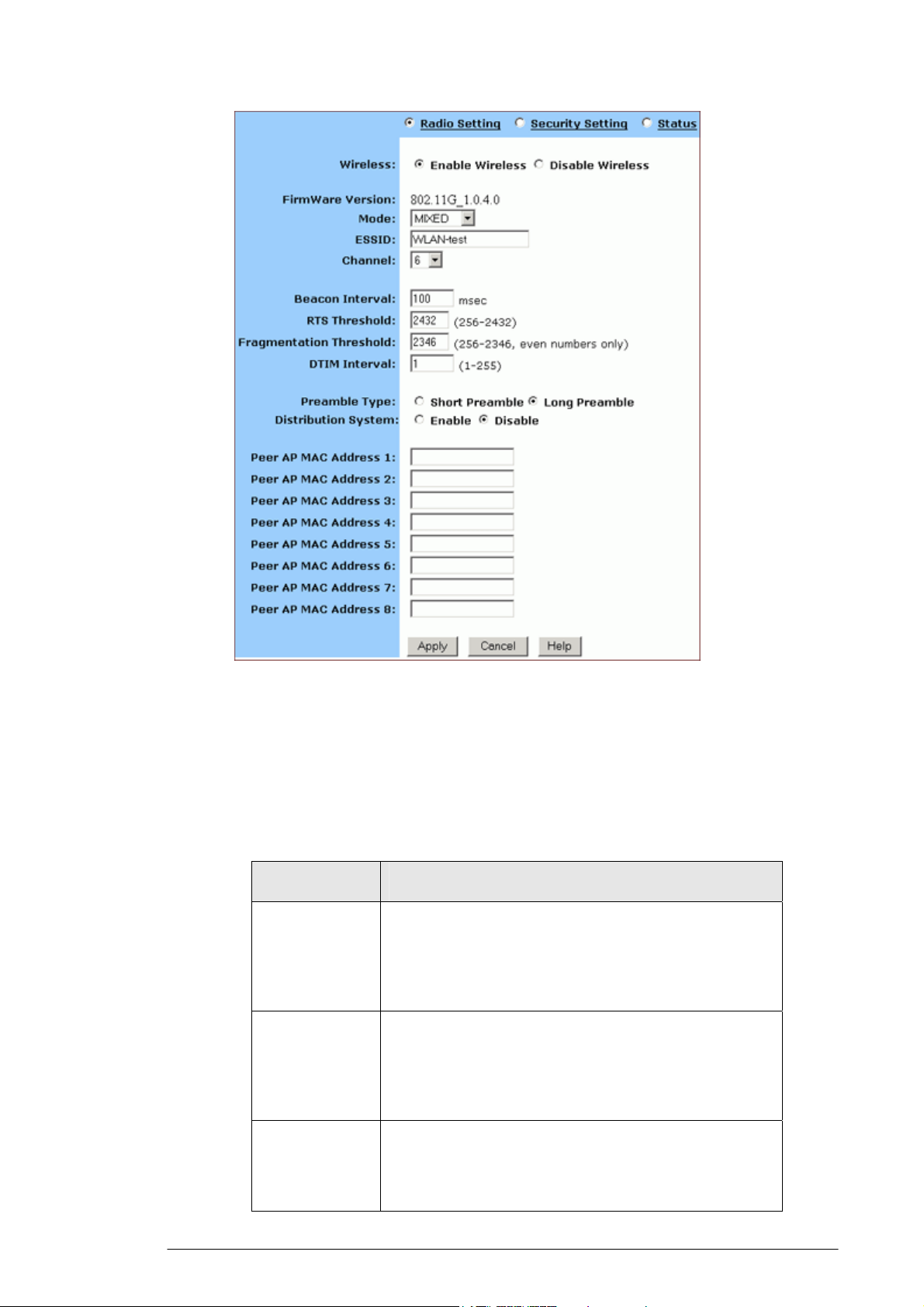
FIGURE 4-7: Wireless – Radio Settings Page
4.4.1.2. Click Enable next to Wireless.
4.4.1.3. Optional. Review the firmware version number and date
information that you are currently using.
4.4.1.4. Enter the following basic radio parameters:
Parameter Description
Mode
ESSID
Selects the Wireless Mode that your Company AP
Router supports from the drop-down list.
Available options are 802.11B, 802.11G, and
MIXED which supports both 802.11B and 802.11G.
Type the unique identifier for the Extended Service
Set which is shared by client stations in an
infrastructure association, such as WLAN-test.
It is case-sensitive and cannot exceed 32 characters.
Channel
Selects one IEEE 802.11G channel for wireless
LAN transmissions from the drop-down list.
Specifies the bandwidth which the wireless radio
operates. AP and the client stations that is
15
Page 21

associated work in one of channels from 1 to 14.
4.4.1.5. Enter the following advanced radio parameters:
Parameter Description
Beacon
Interval
RTS Threshold
Fragmentation
Threshold
DTIM Interval
Type the time interval in milliseconds
between beacons broadcast by AP (Access
Point) in the Beacon Interval box, such as 100.
Type a number in the RTS Threshold box.
Also called Request-to-Send Threshold. This
field specifies the minimum size of data
frames above which RTS protocol is used,
ranging from 256 to 2432. RTS helps prevent
data collision from hidden nodes.
Type a number in the Fragmentation
Threshold box.
For efficiency in high-traffic situations, large
files are split into fragments. This field
specifies the default packet size, an even
number ranging from 256 to 2346.
Type a number in the DTIM Interval box.
Also called Delivery Traffic Indication Map.
This field specifies the number of beacon
intervals between successive DTIMs, ranging
from 1 to 255.
Preamble Type
Distribution
System
Select either Short Preamble (72 bits) or Long
Preamble (144 bits).
If you want to use Wireless Distribution
System on your Router, click Enable next to
Distribution System, then type the distributed
client PCs’ physical addresses, as described
in Step 6.
Otherwise, click Disable.
Note :
You can see the default values of the above advanced wireless settings
on the right of the page. If you don’t know how to change the settings,
please leave as they are in Figure 4-8:
16
Page 22
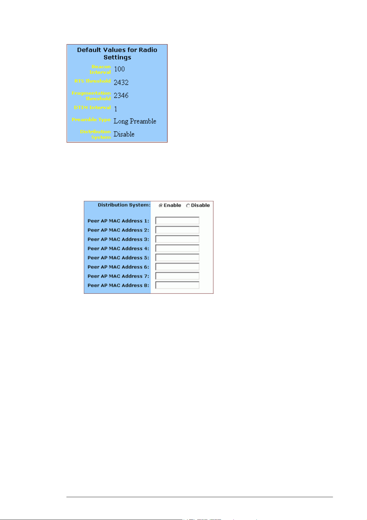
FIGURE 4-8: Default Values for Radio Settings
4.4.1.6. Optional. If you have enabled Distribution System, type the
physical addresses of distributed client PCs in a wireless
network in the Peer AP MAC Address 1-8 boxes, seen in
FIGURE 4-9:
FIGURE 4-9: Peer AP MAC Addresses for Distribution Systems
4.4.1.7. When you have completed editing all the settings, click Apply, or
click Cancel to undo your changes.
4.4.2. To Set Wireless Security Parameters:
4.4.2.1. Click Security Settings on the Wireless page.
The Security Settings appears, seen in FIGURE 4-10:
17
Page 23
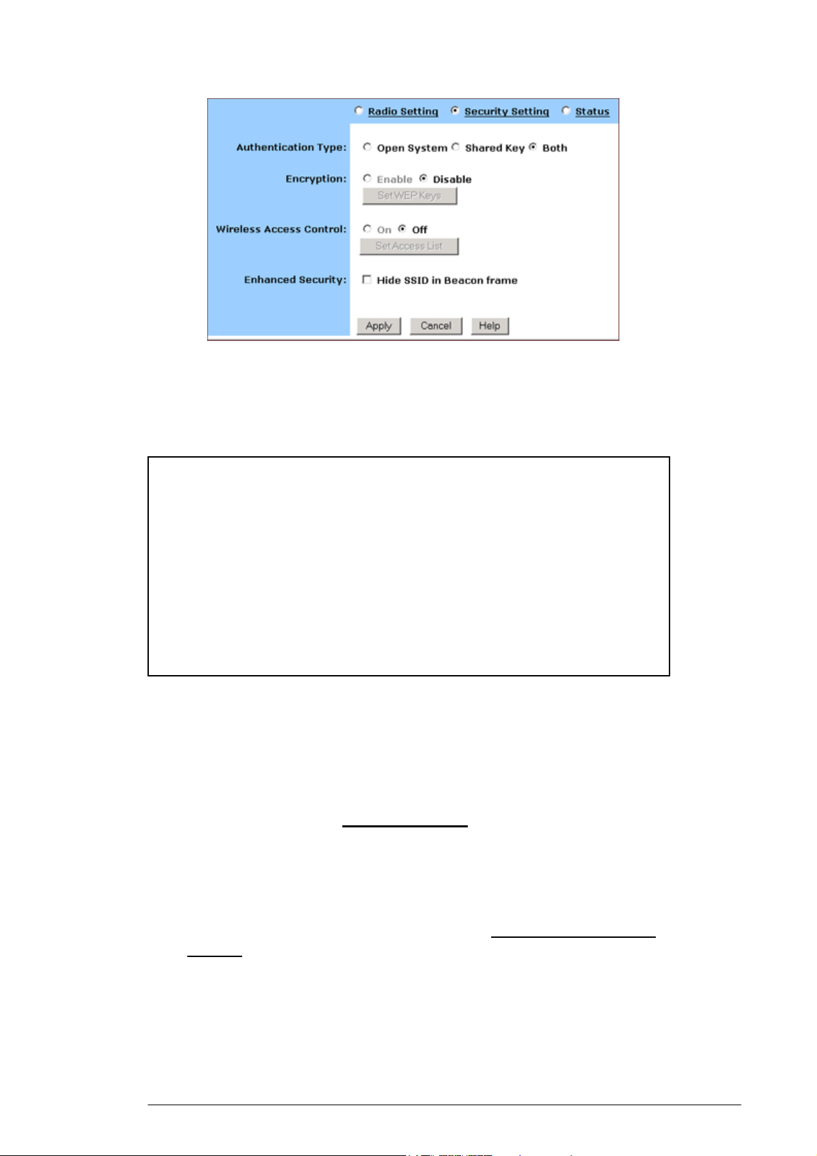
FIGURE 4-10: Wireless – Security Settings Page
4.4.2.2. Select one of Open System, Shared Key and Both from the
Authentication Type drop-down list.
Notes :
Authentication Type indicates an authentication algorithm which can
be supported by the Access Point:
Open System: The simplest of available authentication algorithms.
Essentially it is a null algorithm. Any station that requests
authentication with this algorithm may become authenticated if Open
System is set at the recipient station.
Shared Key: Allows stations with a specific WEP (Wired Equivalent
Privacy) Keys to be authenticated.
Both: Supports the authentications of either stations who know a
shared key or those who do not.
If you want to prevent other stations without specific WEP (Wired
Equivalent Privacy) keys from linking to the AP, select Enable next
to Encryption and then click Set WEP Keys to specify relevant keys;
otherwise, select Disable. For detailed instructions on how to set the
WEP Keys, see below To Set WEP Keys.
If you want to allow access to the Internet based on user’s MAC
(Media Access Control) address, select On next to Wireless Access
Control and then click Set Access List to specify relevant MAC
addresses; otherwise, click Off. For detailed instructions on how to
specify relevant MAC addresses, see below To Set Wireless Access
Control.
4.4.2.3. Next to Enhanced Security, select either Enable or Disable. If
you choose to enable the enhanced security feature, go to Step
6.
18
Page 24
4.4.2.4. Optional. If you have enabled Enhanced Security, you can
choose to hide your SSID (Service Set Identifier) in Beacon
frame.
4.4.2.5. When you have completed editing all the settings, click Apply,
or click Cancel to undo your changes.
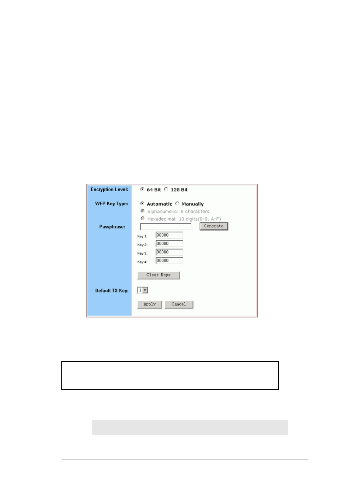
4.4.3. To Set WEP Keys:
4.4.3.1. On the Security Settings page, enable the Encryption and click
Set WEP Keys.
The Set WEP Keys window appears, seen in FIGURE 4-11:
FIGURE 4-11: Set WEP Keys Window
4.4.3.2. Select either 64 Bit or 128 Bit next to Encryption Level.
Note :
128 Bit encryption can provide you a more secure encryption
algorithm, but it will slow down your network data transmission rates.
4.4.3.3. If you want to generate WEP Keys automatically, do the
following action:
4.4.3.3.1. Select Automatic next to WEP Key Type.
19
Page 25

4.4.3.3.2. Type a string of any words in the Passphrase box,
and click Generate.
Four newly generated WEP Keys will display in the Key
1 – Key 4.
4.4.3.3..3. Optional. Click Clear Keys to reset all the keys to
null.
Note :
Make sure that you write down the passphrase string, so that you can
refer to it if necessary.
4.4.3.4. If you want to enter the key elements manually, do the following
action:
4.4.3.4.1. Select Manually next to WEP Key Type.
4.4.3.4.2. If you select Alphanumeric: 5 characters, type a
string of 5 alphanumeric characters in the Key 1 –
Key 4 boxes respectively.
4.4.3.4.3. If you select Hexadecimal: 10 digits (0-9, A-F), type
a string of 10 hexadecimal digits in the Key 1 – Key
4 boxes respectively.
4.4.3.4.4. Optional. Click Clear Keys to reset all the keys to
null.
4.4.3.5. Select the default encryption key from the Default TX Key
drop-down list, such as Key 1.
4.4.3.6. When you have completed editing all the settings, click Apply,
or click Cancel to undo your changes.
4.4.4. To Set Wireless Access Control:
4.4.4.1. On the Security Settings page, set the Wireless Access Control
On and click Set Access List.
The Window Control List window appears, seen in FIGURE
4-12:
20
Page 26
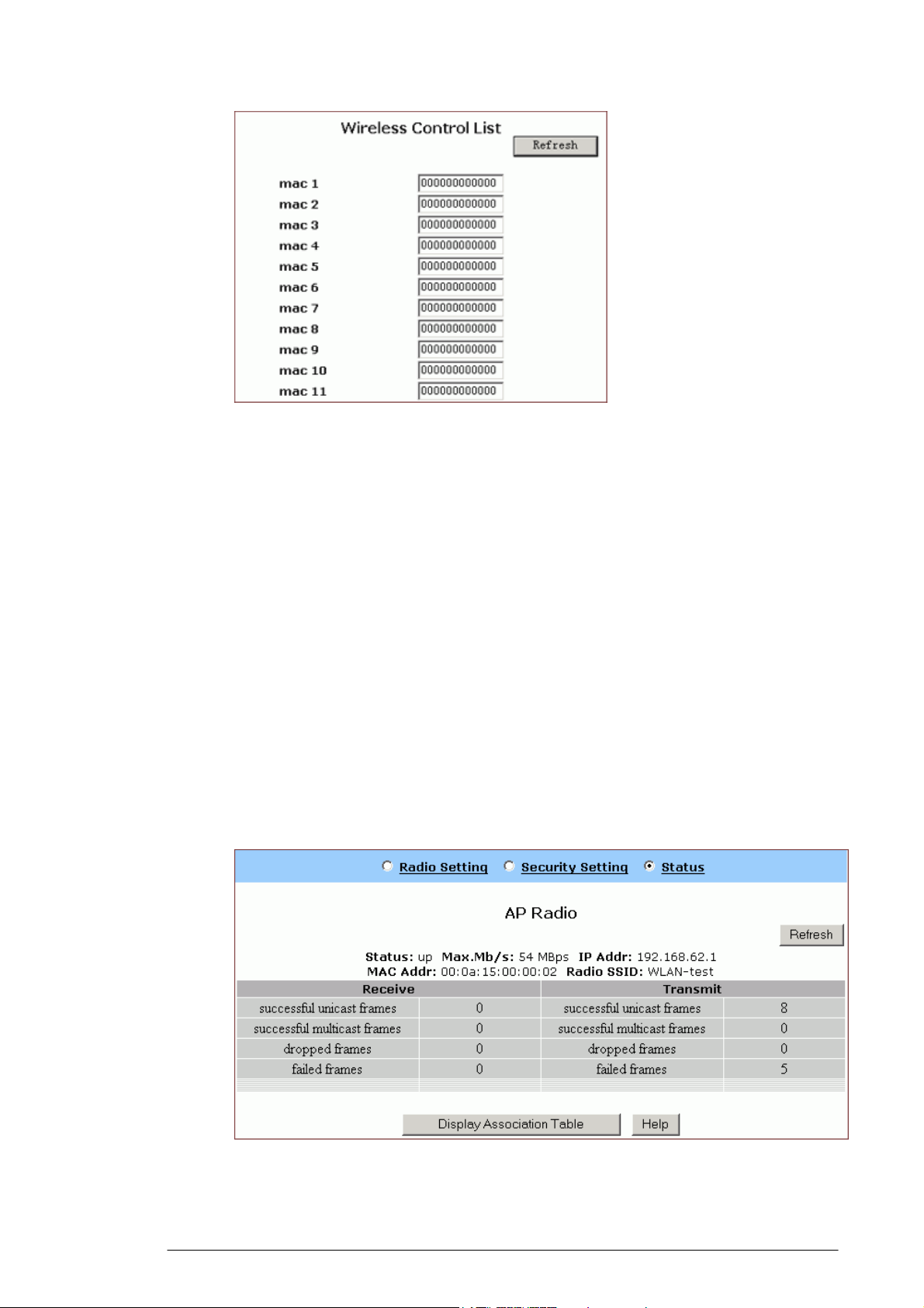
FIGURE 4-12: Wireless Control List window
4.4.4.2. Type the MAC addresses that you want to allow to access the
Internet. You can specify up to 80 MAC addresses in the list.
4.4.4.3. When you have complete editing all the MAC addresses, click
Submit, or click Cancel to undo your changes.
4.4.4.4. Optional. You can click Refresh to see the most current MAC
addresses in effect.
4.4.5. To Review Wireless Status:
4.4.5.1. On the Wireless page, select Status.
The Status page appears with your GateWay’s AP Radio
statistics including Status, Max.Mb/s, IP Addr, MAC Addr, Radio SSID,
Receive data and Transmit data. Seen in FIGURE 4-13:
FIGURE 4-13: Wireless – Status Page
21
Page 27
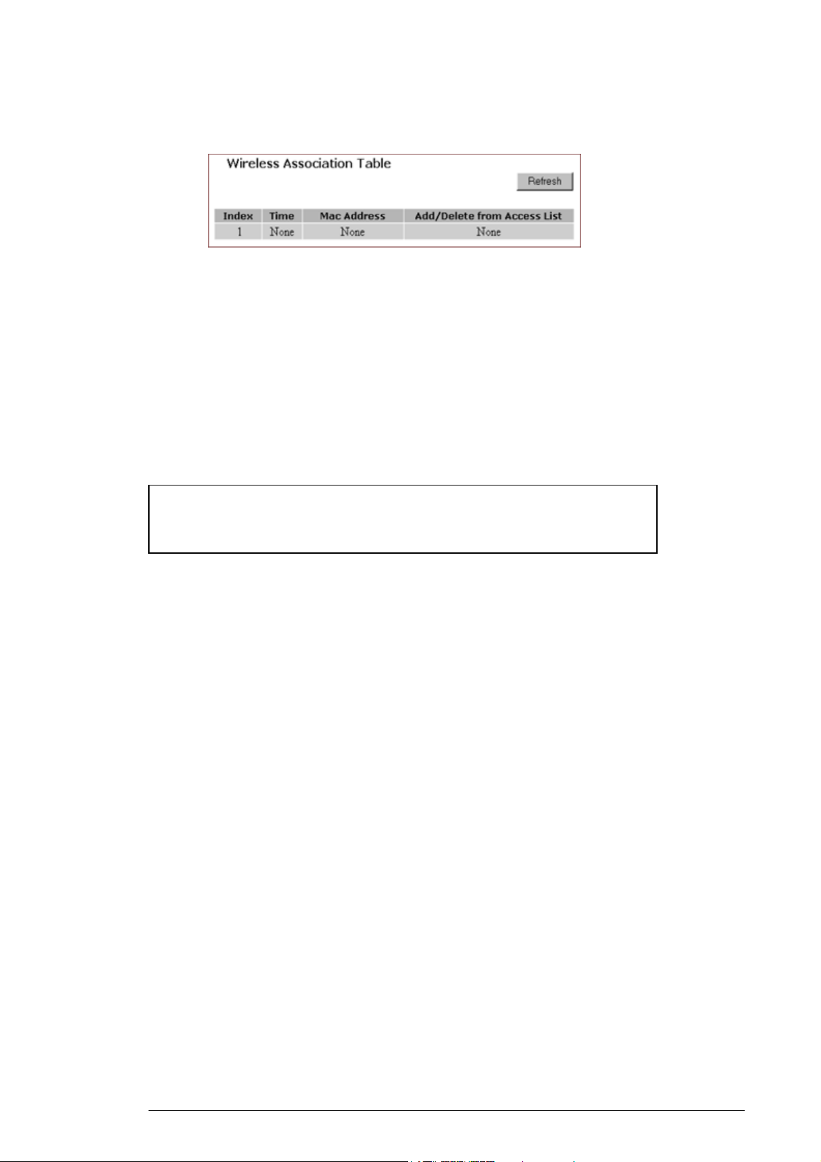
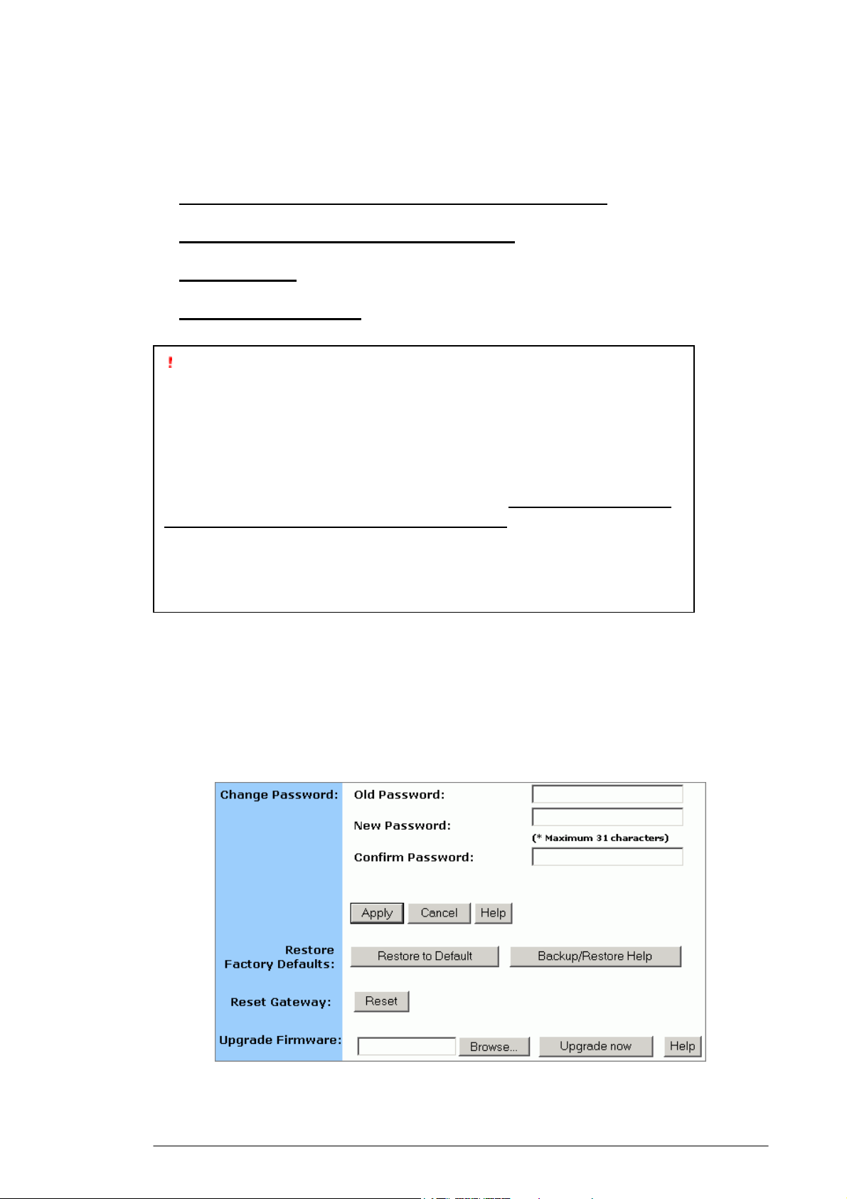
4.4.5.2. To see the wireless devices of which the AP (Access Point) is
aware, click Display Association Table.
4.4.5.3. Optional. You can click Refresh to see the most current data.
4.4.6. To Disable Wireless:
4.4.6.1. On the Wireless page, select Radio Settings.
The Radio Settings page appears, seen in FIGURE 4-7.
If you don’t want the router to support Wireless, select Disable.
Note :
None of the router’s wireless functions will work unless you enable it.
22
Page 28
4.5 Tools
On the Tools page, you can:
▪ Change the Administrative Password for Your Router
▪ Restore the Factory Default Configuration
▪ Reset Gateway
▪ Upgrade the Firmware
Important:
We strongly recommend that you change the administrative password
after the first login.
Restoring the default factory settings will reset all of the router
configurations in every page, so we recommend that you backup the
configuration data from the Gateway to your PC simply using DOS
commands. In addition, you can also restore the factory defaults under
the DOS window. For detailed instructions, see To Backup or Restore
the Configuration Data Using DOS Commands.
If you want to reset the hardware, you need reset the Gateway.
Before upgrading the firmware, you need download the firmware
image file from the Gateway Web site and save it to your root local
drive first.
4.5.1. To Change the Administrative Password for Your
Router:
4.5.1.1. Click Tools on the navigation bar.
The Tools page appears, seen in FIGURE 4-14:
FIGURE 4-14: Tools Page
23
Page 29
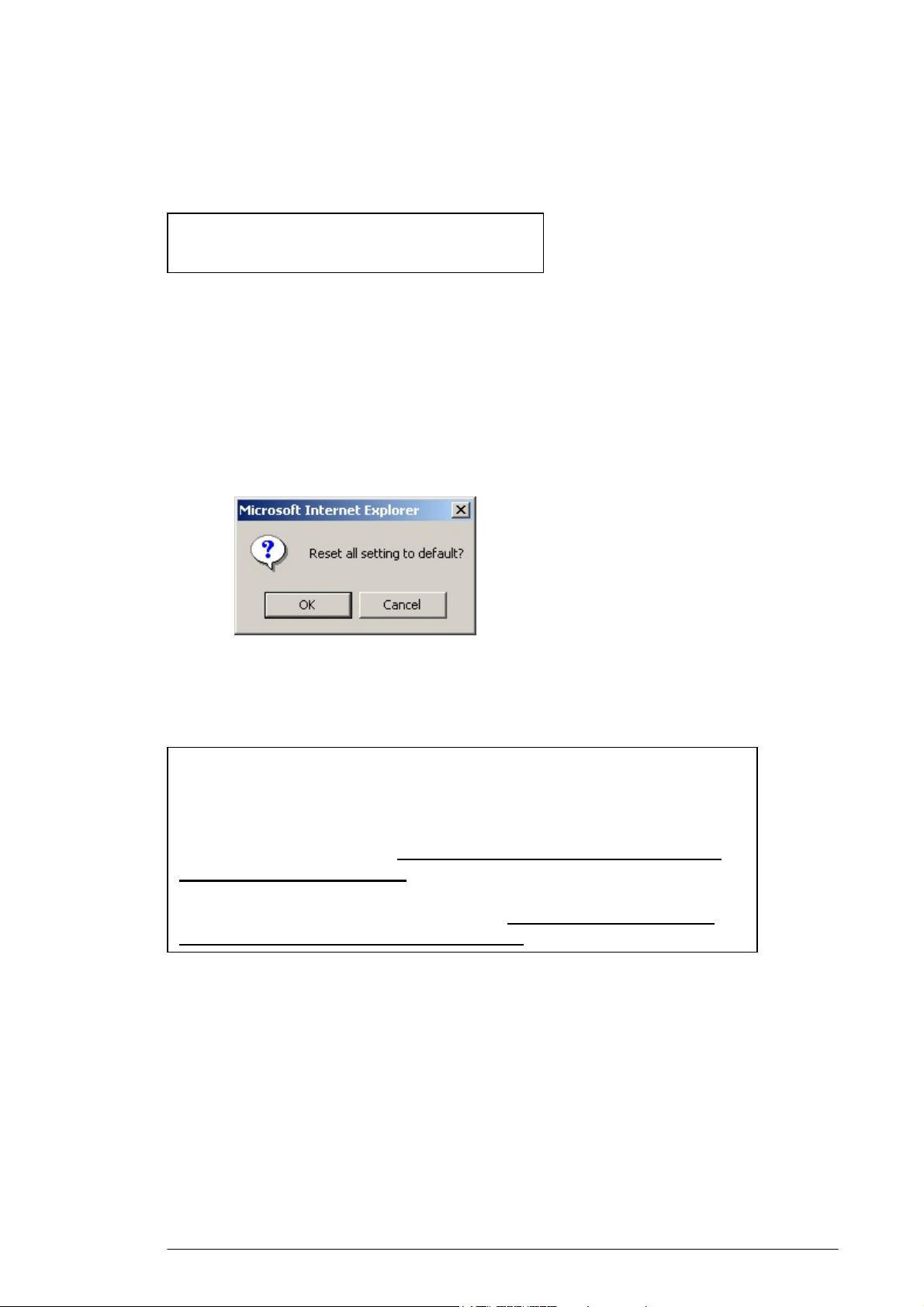
4.5.1.2. Type the Old Password in the box. The default password is
1234.
4.5.1.3. Type a New Password in the box.
Note :
Password must be less than 64 characters.
4.5.1.4. Type the new password in the Confirm Password box.
4.5.2. To Restore the Factory Default Configuration:
4.5.2.1. On the Tools page, click Restore to Default next to Restore
Factory Defaults.
The Warning dialog box appears, see FIGURE 4-15:
FIGURE 4-15: Warning Dialog Box
4.5.2.2. Click OK.
Important:
Restoring the default factory settings will reset all of the router
configurations in every page, so we recommend that you backup the
configuration data from the Gateway to your PC first using DOS
commands. For details, see To Backup or Restore the Configuration
Data Using DOS Commands.
In addition, you can also restore the factory defaults using DOS
commands. For detailed instructions, see To Backup or Restore the
Configuration Data Using DOS Commands.
4.5.3. To Backup or Restore the Configuration Data Using
DOS Commands:
For the backup of the configuration data from the Gateway to your
PC, Gateway acts as a TFTP server.
To backup the configuration data, under the DOS window, use the
following command:
tftp –i gateway_Ip_address GET filename
24
Page 30
To restore the configuration data, under the DOS window, use the
following command:
tftp –i gateway_Ip_address PUT filename
gateway_Ip_address: The IP address of the Gateway where you
want to back the configuration data.
filename: The file name for backup from the Gateway. It must begin
with “nvram” which is not case-sensitive, such as
“nvram__11032003”.
4.5.4. To Reset Gateway:
If you want to reset the hardware, click Reset next to Reset Gateway
on the Tools page.
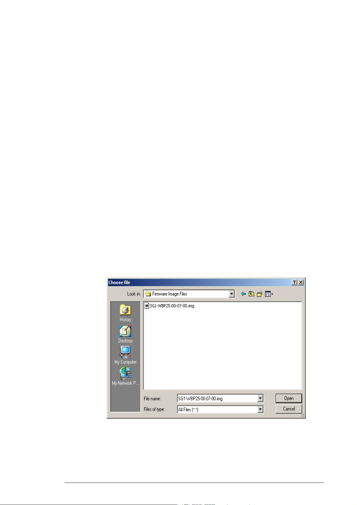
4.5.5. To Upgrade the Firmware:
4.5.5.1. Download a firmware image file from the Gateway Web site and
save it to your root local drive.
4.5.5.2. Type the file path and file name in the Upgrade Firmware box,
or click Browse to launch a Choose file dialog box, seen in
FIGURE 4-15:
FIGURE 4-15: Choose File Dialog Box for Upgrading
Firmware
4.5.5.3. Locate the firmware you have downloaded and click Open.
25
Page 31

4.5.5.4. The Choose file dialog box closes.
4.5.5.5. Click Upgrade Now. The firmware of the device will be
upgraded.
Caution :
The firmware upgrade may take about 10 seconds, please DONOT
power off the unit when it is being upgraded.
26
Page 32

4.6 Status
On the Status page, you can view the most current information
about your Router which will be continuously refreshed per 10
seconds, such as Host Name, Domain, PPPoE Login, LAN/WAN and
DDNS Status. Different configuration may bring you to different
data, compared in FIGURE 3-16 and FIGURE 4-17.
Note :
If you want to change the configuration, go to the Setup page. For
detailed instructions, see Setup.
▪ If you have enabled the PPPoE Login, the Status page will
display as illustrated in FIGURE 4-16:
FIGURE 4-16: Status Page with PPPoE Login Enabled
▪ If you have chosen the Dynamic IP and disabled PPPoE Login,
the Status page will display as illustrated in FIGURE 4-17:
▪
27
Page 33

FIGURE 4-17: Status Page with PPPoE Login Disabled
Notes :
If you have chosen the Dynamic IP and disabled PPPoE Login, you can
see the DHCP Release and DHCP Renew buttons:
To release the most current WAN IP address, click DHCP Release.
To renew the WAP IP address, click DHCP Renew.
Status Detail:
Parameter Description
Host
Name
Domain
PPPoE
Login
Shows the name of the device.
Shows the domain name of the device.
Shows the current status of PPPoE Login:
LAN
WAN
▪ Disabled
▪ Enabled: Connected, Connecting or
Disconnected.
Shows the current IP Address and Subnet Mask of
the device, as seen by users in your internal
network.
Shows the IP Address, Subnet Mask, Default
Gateway, and DNS of the router, as seen by
28
Page 34

external users on the Internet.
DDNS
Shows the Dynamic DNS Server and Status.
If you want to change the setting, go to the
Advanced Dynamic DNS page. For details
instructions, see To Configure a Dynamic DNS
Server.
29
Page 35

4.7 DHCP
On the DHCP page, you can set your NAT/Firewall Gateway as a
DHCP (Dynamic Host Configuration Protocol) server, and DHCP
servers will automatically assign IP addresses to all the client PCs in
your network.
Notes
If you want to enable DHCP, make sure that there is not already a
DHCP server on your router.
If you don’t enable DHCP on your router, you will need to manually
configure an IP address for each PC in your network; if you do enable
DHCP, make sure that each PC is configured to receive an IP address
automatically.
What do you want to do then?
▪ Set Your Router as a DHCP Server
▪ View the Active IP Table
▪ Disable DHCP on Your Router
4.7.1. To Set Your Router as a DHCP Server:
4.7.1.1. Make sure that there is not already a DHCP server on your
router.
4.7.1.2. Make sure that each PC in your network is configured to receive
an IP address automatically.
4.7.1.3. Click DHCP on the navigation bar.
The DHCP page appears, seen in FIGURE 4-18:
FIGURE 4-18: DHCP Page
4.7.1.4. Click Enable next to DHCP Server.
30
Page 36

4.7.1.5. Type a IP Pool Starting Address to designate the first IP address
that can be assigned to a PC in your network.
4.7.1.6. Type a IP Pool Ending Address to designate the last IP address
that can be assigned to a PC in your network.
4.7.1.7. When you have completed editing all the settings, click Apply,
or click Cancel to undo your changes.
4.7.2. To Disable DHCP on Your Router:
4.7.2.1. On the DHCP page, click Disabled next to DHCP Server.
4.7.2.2. Click Apply.
4.7.3 To View the Active IP Table:
If you want to find out the information about PCs that have been
assigned IP addresses by the DHCP server, click Display DHCP
Table.
DHCP Server IP Address, Client Host Name, IP Address and MAC
Address for each active client PC will be listed out in the table, seen in
FIGURE 4-19:
FIGURE 4-19: DHCP Active IP Table
Optional. Click Refresh to obtain the most current data.
Note :
If you have enabled the DMZ and LAN features, you can also find the
relevant information in the DHCP Active IP Table for DMZ Zone and
the DHCP Active IP Table for LAN.
31
Page 37

4.8 Log
On the Log page, you can set up Access Log and view log files that
record the access activity of LAN and WAN client PCs, including
Session Event Log, Block Event Log, Intrusion Event Log and
Wireless Event Log.
What do you want to do?
▪ Set up Access Log on Your Router
▪ View Session Event Log
▪ View Block Event Log
▪ View Intrusion Event Log
▪ View Wireless Event Log
4.8.1. To Set up Access Log on Your Router:
4.8.1.1. Click Log on the navigation bar.
The Log page appears, seen in FIGURE 4-20:
FIGURE 4-20: Log Page
4.8.1.2. Select Enable.
4.8.1.3. Click Apply, or click Cancel to undo your changes.
4.8.2. To View Session Event Log:
4.8.2.1. Click Session Event Log on the Log page.
The Session Event Log Table appears, including each session
event entry information like Record Name, Transport type, Source IP
and so on, seen in FIGURE 4-21:
32
Page 38

FIGURE 4-21: Session Event Log Table
4.8.2.2. Optional. Click Refresh to obtain the most current data.
4.8.2.3. Optional. Click Clear to delete all the log information.
4.8.3. To View Block Event Log:
4.8.3.1. Click Block Event Log on the Log page.
The Block Event Log Table appears, including each block event
entry information like Record Name, Transport type, Source IP and so
on, seen in FIGURE 4-22:
FIGURE 4-22: Block Event Log Table
4.8.3.2. Optional. Click Refresh to obtain the most current data.
4.8.3.3. Optional. Click Clear to delete all the log information.
4.8.4. To View Intrusion Event Log:
4.8.4.1. Click Intrusion Event Log on the Log page.
The Intrusion Event Log Table appears, including each intrusion
event entry’s Record Name and Intrusion Type, seen in FIGURE 4-23:
33
Page 39

FIGURE 4-23: Intrusion Event Log Table
4.8.4.2. Optional. Click Refresh to obtain the most current data.
4.8.4.3. Optional. Click Clear to delete all the log information.
4.8.5. To View Wireless Event Log:
4.8.5.1. Click Wireless Event Log on the Log page.
The Session Event Log Table appears, including each wireless
event entry’s Time, Severity and Description, seen in FIGURE 4-24:
FIGURE 4-24: Wireless Event Log Table
4.8.5.2. Optional. Click Refresh to obtain the most current data.
4.8.5.3. Optional. Click Clear to delete all the log information.
4.8.6. To Disable Access Log on Your Router:
4.8.6.1. On the Log page, click Disabled next to Access Log.
4.8.6.2. Click Apply.
34
Page 40

4.9 Statistics
On the Statistics page, you can view the statistics information of
LAN, WAN and AP (Access Point) Radio ports, including Status,
Max.Mb/s, IP Addr and MAC Addr, Receive data and Transmit data.
You can click Statistics on the navigation bar, and then the Statistics
page appears, seen in FIGURE 4-25:
FIGURE 4-25: Statistics Page
4.9.1. The Statistics page includes three parts:
4.9.1.1. LAN Statistics: Lists out the data on the LAN port.
4.9.1.2. WAN Statistics: Lists out the data on the WAN port.
4.9.1.3. AP Radio: Lists out the data on the Access Point’s
radio.
Note :
You can also click Refresh in any part above to obtain the most current
data.
35
Page 41

5. Advanced Function
In this chapter, you will learn how to use the advanced
administrative functions that the Company AP Router provides,
including Virtual Server, Filters, IP/URL Block, Special Apps, DMZ
Host, MAC Clone, Dynamic DNS, Proxy DNS and SNMP.
The Web-based Administration Tool provides you some advanced
services on the Advanced Function navigation bar, such as Filtering
and cloning your MAC addresses.
In most cases, basic functions are Okay. If you want to set the
advanced configuration, you will need to toggle to the Advanced
Function navigation bar first.
5.1. To Toggle between Basic Functions and Advanced
Functions:
5.1.1. To toggle to the Advanced window, click Advanced on the
right side of the Basic window, seen in FIGURE 5-1:
FIGURE 5-1: Advanced Button on the Basic Window
5.1.2. Once you are already in the Advanced window, click Basic on
the right side of the Advanced window to return to the Basic
Window, seen in FIGURE 5-2:
FIGURE 5-2: Advanced Button on the Basic Window
36
Page 42

5.2 Virtual Servers
In some situations, you might want users on the Internet to be able
to access servers on your LAN, such as an FTP Server, Telnet
Server or Web Server. Such remote services are accomplished by
creating Virtual Server.
Each virtual server has its own IP address and shares a single public
IP address. It is defined by the Protocol type (TCP, UDP or Both)
and a TCP/UDP/Both port number. Only the enabled virtual
servers can be accessed by remote users over the Internet.
Note :
Configuring virtual servers may cause filters to be automatically
created on the Filters page.
What do you want to do?
▪ Set up a Client PC on the LAN as a Virtual Server
▪ Delete Virtual Servers on the LAN
5.2.1. To Set up a Client PC on the LAN as a Virtual Server:
5.2.1.1. On the Advanced navigation bar, click Virtual Servers.
The Virtual Servers page appears with a list of existing virtual
servers, seen in FIGURE 5-3:
FIGURE 5-3: Virtual Servers Page
5.2.1.2. If you have enabled DMZ and your Gateway is not configured
to retrieve an IP address automatically, select either of the
following options from the Choose Interface drop-down list:
37
Page 43

(1) External – Internal: To set up Virtual Server in your LAN
network.
(2) External – DMZ: To set up Virtual Servers in your DMZ
network.
5.2.1.3. If you are using the Windows XP operating system, type a
remote service name in the Service box.
Note :
It is only available for client PCs using Windows XP. Because Windows
XP takes an advantage of the UPnP (Universal Plug and Play) feature
of the Company AP Router, it allows client PCs that support UPnP to
identify the router automatically.
5.2.1.4. Select a Public IP Address from the drop-down list.
Note :
The IP Address of a DMZ host will not appear in the list.
Type a port number in the Public Port and Private Port boxes,
such as 80 for HTTP. For help on which port to choose, refer to
Well-known Ports on the right of the page, seen in FIGURE 5-4:
FIGURE 5-4: Well-know Ports
Notes :
Public Port is the TCP/UDP/Both port number used by the server PC
on the WAN. It is also called the external port number because this
port number is visible to the users on the Internet.
Private Port is the TCP/UDP/Both port number used by the server PC
on the LAN. The designated Public Port will be translated into this
internal port number
.
5.2.1.5. Select one of TCP, UDP and Both from the Protocol drop-down
list.
38
Page 44

5.2.1.6. Type a local IP address of the server PC on the LAN in the
Private IP Address box.
5.2.1.7. When you have completed editing all the settings, click Apply,
or click Cancel to undo your changes.
5.2.2. To Delete Virtual Servers on the LAN:
5.2.2.1. On the Advanced navigation bar, click Virtual Servers.
A list of existing virtual servers appears.
5.2.2.2. For any virtual server you want to delete, select 0.0.0.0 from the
Public IP Address drop-down list.
5.2.2.3. Click Apply.
39
Page 45

5.3 Filters
On the Filters page, you can set up filters that can selectively allow
traffic to pass in and out of your network. The Company AP Router
comes with 9 factory default filters for you.
In addition to 9 default filters, some filters may be created
automatically to allow Virtual Servers or Special Applications to
function.
We strongly recommend that you choose an empty row when you
want to set up new filters, because overwriting or deleting these
filters may cause some services to be disabled, for example, your
client PCs may NOT be able to access the Internet.
Note – If you have overwritten or deleted the factory default filters, you
can retrieve them at a later time using the Restore Factory Defaults
function on the Tools page. For detailed instructions, see To Restore the
Factory Default Configuration.
What do you want to do?
▪ Set up a Port Filtering or Raw IP Filter
▪ Delete a Port Filtering or Raw IP Filter
5.3.1. To Set up a Port Filtering or Raw IP Filter:
5.3.1.1. On the Advanced navigation bar, click Filters.
The Filters page appears, seen in FIGURE 5-5:
40
Page 46

FIGURE 5-5: Filters Page
5.3.1.2. Select an option from the Filtering Page drop-down list: 1~12,
13~24, 25~36.
5.3.1.3. If you select Port Filtering from the Filtering Layer drop-down
list, do the following action:
5.3.1.3.1. Select a traffic direction from the drop-down list:
Inbound, Outbound and Both.
5.3.1.3.2. Type the start port number and end port number
that you want to allow in the Private Port Range
boxes.
5.3.1.3.3. Select a protocol type from the drop-down list:
TCP, UDP and Both.
5.3.1.4. If you select Raw IP from the Filtering Layer drop-down list, do
the following action:
41
Page 47

5.3.1.4.1. Type an IP Protocol Number in the Proto Num
Note - It ranges from 0 to 255, but can not be 6 (TCP)
box.
or 17 (UDP); otherwise, this port filter will not work.
5.3.1.4.2. Select a traffic direction from the drop-down list:
Inbound Outbound and Both.
5.3.1.4.3. Select an option from the Protocol drop-down
list: TCP, UDP and Both.
5.3.1.5. Optional. Select Enable or Disable for the following additional
filtering options:
Parameter Description
NAT
Firewall
Remote
Managem
ent
IPSec
Pass
Through
PPTP
Pass
Through
Intrusion
Detect
Allows you to set up NAT (Network Access
Translation).
Allows you to protect your network with a firewall.
Allows you to access your router’s Web-based
Administration Tool through your WAN
connection.
Allows you to use IP Security Pass Through.
Allows you to use PPTP (Point-to-Point Tunneling
Protocol), used to enable VPN sessions.
Allows you to detect and record intrusion attempts
into your network.
5.3.1.6. When you have completed editing all the settings, click Apply,
or click Cancel to undo your changes.
5.3.2. To Delete Filters:
You can delete any existing Port Filtering or Raw IP filer, but make
sure that you are deleting an unwanted one, otherwise deleting the
42
Page 48

filters associated with Virtual Servers or Special Applications may
cause to services to collapse down.
5.3.2.1. To Delete a Port Filtering Filter:
5.3.2.1.1. On the Filters page, for any Raw IP filter you want to delete,
type 0 in the Private Port Range boxes.
5.3.2.1.2. Click Apply.
5.3.2.2. To Delete a Raw IP Filter:
5.3.2.2.1. On the Filters page, for any Raw IP filter you want to delete,
type 0 in the Proto Num box.
5.3.2.2.2. Click Apply.
43
Page 49

5.4 IP/URL Block
On the IP/URL Block page, you can create filters that can
selectively block users from specific IP addresses and domain names
to pass in and out of your network. The Company AP Router
provides two ways of blocking users:
▪ IP Block: Allows you to block a single IP address or a range of
IP addresses.
▪ URL Block: Allows you to block up to 36 domain names.
Note – This IP/URL Block feature will block in both directions from
specified IP addresses or domain names.
What do you want to do?
▪ Block a Single IP Address
▪ Block a Range of IP Address
▪ Block a Specific Domain Name
▪ Delete a Specific or All IP Blocks
▪ Delete a Specific or All URL Blocks
5.4.1. To Block a Single IP Address:
Do either of the following:
5.4.1.1. Click IP/URL Block on the Advanced navigation bar.
5.4.1.2. If you are on the URL Block page, select IP Block on the upper
of the page.
The IP Block page appears, seen in FIGURE 5-6:
FIGURE 5-6: IP Block Page
5.4.1.3. In Line 1 – Line 6, type the same IP addresses in both IP Block
Starting Address and IP Block Ending Address boxes
respectively.
44
Page 50

5.4.1.4. Optional. You can click Clear All to conveniently delete all the
existing IP addresses and then do Step 2.
5.4.1.5. When you have completed editing all the IP addresses you want
to block, click Apply, or click Cancel to undo your changes.
5.4.2. To Block a Range of IP Address:
5.4.2.1. Do either of the following:
Click IP/URL Block on the Advanced navigation bar.
If you are on the URL Block page, select IP Block on the upper
of the page.
The IP Block page appears, seen in FIGURE 4-6.
5.4.2.2. In Line 1 – Line 6, type the different IP addresses in both IP
Block Starting Address and IP Block Ending Address boxes
respectively.
5.4.2.3. Optional. You can click Clear All to conveniently delete all the
existing IP addresses and then do Step 2.
5.4.2.4. When you have completed editing all the IP addresses you want
to block, click Apply, or click Cancel to undo your changes.
5.4.3. To Block a Specific Domain Name:
5.4.3.1. Click IP/URL Block on the advanced navigation bar.
The IP Block page appears, seen in FIGURE 5-6.
5.4.3.2. Select URL Block on the IP Block page.
The URL Block page appears, seen in FIGURE 5-7:
FIGURE 5-7: URL Block Page
5.4.3.3. In Line 1 – Line 36, type the URLs you want to block.
45
Page 51

5.4.3.4. Optional. You can click Clear All to conveniently delete all the
existing URLs and then do Step 2.
5.4.3.5. When you have completed editing all the domain names you
want to block, click Apply, or click Cancel to undo your
changes.
5.4.4. To Delete a Specific or All IP Blocks:
5.4.4.1. On the IP Block page, do either of the following:
For any IP block you want to delete, type 0.0.0.0 in both IP Block Starting
Address and IP Block Ending Address boxes respectively.
If you want to delete all IP blocks, click Clear All.
5.4.4.2. Click Apply.
5.4.5. To Delete a Specific or All URL Blocks:
5.4.5.1. On the URL Block page, do either of the following:
For any domain name block you want to delete, clear out the URL in the
box.
If you want to delete all URL blocks, click Clear All.
5.4.5.2. Click Apply.
46
Page 52

5.5 Special Apps
On the Special Apps page, you can authorize certain ports to
communicate with PCs outside your network. It may be necessary
for multi-session applications, such as online games and voice
conferencing.
There are two ways of set up new special applications on your
router:
▪ Popular Application Copy: Allows you to select one of frequently
used applications from the Popular Applications drop-down list
and copy it to your Special Application Table. Available options
are AIM, Diablo II (1), Diablo II (2), StarCraft, StarCraft III,
ICUII, FTP, CUseeMe, MSN Messenger and Real Player.
▪ Manual Configuration: If the application you want to configure
is not in the Popular Applications list, you can configure its
settings manually.
Before configuring a new special application, would you please
check the list of those popular applications first? If it is already in
the list, we recommend that you use the Popular Application Copy
unless you know exactly which settings to choose.
Notes
Configuring special applications may cause filters to be automatically
created on the Filters page.
The Company AP Router provides two factory default special
applications for FTP and NetMeeting, if you overwrite them or any
other existing application, they will not work.
What do you want to do?
▪ Copy a Popular Application to a Specific Line
▪ Configure a Special Application Manually
▪ Delete Special Applications
5.5.1. To Copy a Popular Application to a Specific Line:
5.5.1.1. On the Advanced navigation bar, click Special Apps.
The Popular Applications list appears on the Special Apps page,
seen in FIGURE 5-8:
47
Page 53

FIGURE 5-8: Popular Applications List
5.5.1.2. Select an option from the Popular Applications drop-down
list, including AIM, Diablo II (1), Diablo II (2), StarCraft,
StarCraft III, ICUII, FTP, CUseeMe, MSN Messenger and
Real Player.
Note :
Make sure the specified ID presents an empty line unless you want to
overwrite an existing application.
Select a specific line number from the ID drop-down list.
5.5.1.3. Click Copy to.
5.5.1.4. The selected application’s configuration is added to your Special
Applications Table on the upper of the page.
5.5.1.5. When you have completed editing all the settings, click Apply,
or click Cancel to undo your changes.
5.5.2. To Configure a Special Application Manually:
5.5.2.1. On the Advanced navigation bar, click Special Apps.
5.5.2.2. The Special Apps page appears, seen in FIGURE 5-9:
48
Page 54

FIGURE 5-9: Special Apps Page
5.5.2.3. Select a line corresponding to a specific ID.
Note :
Make sure you have selected an empty line unless you want to
overwrite an existing application.
Enter the following configuration information:
Parameter Description
Protocol
Trigger
Port
Range
Maximu
m
Activity
Interval
Specifies the communication protocol used by the
application.
Available options are TCP, UDP and Both.
Range of ports used for outgoing traffic. It will
trigger the Gateway to accept certain incoming
requests.
Maximum number of miliseconds after the port
trigger function, within which incoming requests
will be accepted.
Session
Chaining
Chaining
on UDP
Allows you to select either Enable or Disable.
Specifies whether dynamic sessions can be chained,
allowing multi-session triggering.
Allows you to select Enable or Disable only when
Session Chaining is enabled.
Specifies whether the session chaining is allowed on
UDP.
49
Page 55

Address
Replacem
Allows you to select Enable or Disable only when
Chaining on UDP is enabled.
ent
Specifies whether binary address replacement
should be performed.
Address
Translati
Allows you to select TCP or UDP only when
Address Replacement is enabled.
on Type
Specifies whether address translation is performed
on TCP or UDP packets.
Two Way
Allows you to select either Enable or Disable.
Only
Specifies that a new session is allowed to be
initiated from the same remote host.
5.5.2.4. When you have completed editing all the settings, click Apply,
or click Cancel to undo your changes.
5.5.3. To Delete Special Applications:
5.5.3.1. On the Special Apps page, for any application you want to
delete, type 0 – 0 in the Trigger Port Range box.
5.5.3.2. Click Apply.
50
Page 56

5.6 DMZ Host
On the DMZ Host page, you can expose one or more client PCs in
your network to the Internet. It is often used for online games that
require unstricted two-way communications.
The total number of DMZ (Demilitarized Zone) hosts you can have
depends on how many Global Addresses you have configured on the
Global Address page. For example, if you have defined 5 Global
Addresses (including the default IP), you are limited to 5 DMZ hosts.
Since the maximum number of Global Addresses is 8, the total
number of DMZ hosts you can configure is also 8.
Caution :
Once a PC in your network is designated as DMZ host, it will not have
any firewall protection.
What do you want to do?
▪ Designate a PC in Your Network as a DMZ Host
▪ Delete DMZ Hosts
5.6.1. To Designate a PC in Your Network as a DMZ Host:
5.6.1.1. On the Advanced navigation bar, click DMZ Host.
The DMZ Host page appears, seen in FIGURE 5-10:
FIGURE 5-10: DMZ Host Page
5.6.1.2. Select a Public IP Address from the drop-down list.
5.6.1.3. Type the IP address of a PC in your network that you want to
designate as a DMZ Host in the Private IP Address box.
5.6.1.4. When you have completed editing all the settings, click Apply,
or click Cancel to undo your changes.
51
Page 57

5.6.2. To Delete DMZ Hosts:
5.6.2.1. On the DMZ Host page, for any DMZ host you want to delete,
select 0.0.0.0 from the Public IP Address drop-down list.
5.6.2.2. Click Apply.
52
Page 58

y
5.7 MAC Clone
If your ISP restricts services at a PC level, using MAC Clone, you
can copy a PC MAC (Media Access Control) address to the router.
Then what story will begin? The router will appear as a single PC,
and multiple PCs in your network will access the Internet via this
“Single PC”.
5.7.1. To Clone the MAC Address:
5.7.1.1. On the Advanced navigation bar, click MAC Clone.
The MAC Clone page appears with the current WAN port
address and the factory default MAC address for your convenience,
seen in FIGURE 5-11:
FIGURE 5-11: MAC Clone Page
Note :
You may need to use the Ethernet MAC address of the NIC (Network
Interface Card) that
5.7.1.2. Click Mac Clone, or click Restore to retrieve the default settings.
our PC is registered with your ISP.
53
Page 59

5.8 Dynamic DNS
On the Dynamic DNS page, you can tie up your domain name to a
dynamic DNS provider. These providers allow you to associate a
static hostname with a dynamic IP address, then you can connect to
the Internet with a dynamic IP address and use applications that
require a static IP address.
The Company AP Router supports three dynamic DNS providers:
▪ DynDNS.org
▪ no-IP.com
▪ no-IP.com
What do you want to do?
▪ Configure a Dynamic DNS Server
▪ Disable a Dynamic DNS Server
5.8.1. To Configure a Dynamic DNS Server:
5.8.1.1. On the Advanced navigation bar, click Dynamic DNS.
The Dynamic Server page appears, seen in FIGURE 5-12:
FIGURE 5-12: Dynamic DNS page
5.8.1.2. Select Enable next to Dynamic DNS.
5.8.1.3. Select one of DynDNS.org, no-IP.com, no-IP.com from the
Dynamic DNS Provider drop-down list.
5.8.1.4. Type your Domain Name in the box.
5.8.1.5. Type your Account or E-mail in the box.
5.8.1.6. Type your Password or Key in the box.
5.8.1.7. When you have completed editing all the settings, click Apply,
or click Cancel to undo your changes.
54
Page 60

5.8.2. To Disable a Dynamic DNS Server:
5.8.2.1. On the Dynamic DNS page, select Disable next to Dynamic
DNS.
5.8.2.2. Click Apply.
55
Page 61

5.9 Proxy DNS
On the Proxy DNS page, you can map a domain name to a server IP
address. Acting as a DNS server for internal and DMZ networks, it
allows you to connect to local machines in your network without
using an external DNS server. It simplifies the configuration and
management of your network.
What do you want to do?
▪ Configure a Proxy DNS Server
▪ Delete a Specific or All Proxy DNS Servers
▪ Disable the Proxy DNS on Your Router
5.9.1. To Configure a Proxy DNS Server:
5.9.1.1. On the Advanced navigation bar, click Proxy DNS.
The Proxy DNS page appears, seen in FIGURE 5-13:
FIGURE 5-13: Proxy DNS Page
5.9.1.2. Select Enable next to Proxy DNS.
5.9.1.3. Type a name for one PC in your network that you want to use as
a Proxy DNS server in the Domain Name box.
5.9.1.4. Type the IP address for the PC in the Virtual IP Address box.
56
Page 62

5.9.1.5. Optional. If you want to delete all the existing Proxy DNS
servers first, click Clear All and do Step 3 and Step 4.
5.9.1.6. When you have completed editing all the settings, click Apply,
or click Cancel to undo your changes.
5.9.2. To Delete a Specific or All Proxy DNS Servers:
5.9.2.1. On the Proxy DNS page, for any Proxy DNS server you want to
delete, type 0.0.0.0 in the Virtual IP Address box.
5.9.2.2. If you want to delete all the existing Proxy DNS servers, click
Clear All.
5.9.2.3. Click Apply.
5.9.3. To Disable the Proxy DNS on Your Router:
5.9.3.1. On the Proxy DNS page, for any Proxy DNS server you want to
delete, type 0.0.0.0 in the Virtual IP Address box.
5.9.3.2. If you want to delete all the existing Proxy DNS servers, click
Clear All.
5.9.3.3. Click Apply.
57
Page 63

5.10 SNMP
The Simple Network Management Protocol (SNMP) is an
application layer protocol that facilities the exchange of
management information between network devices. It is part of
TCP/IP (Transmission Control protocol/Internet Protocol) suite and
enables you to control and monitor the network in a simple way.
On the SNMP page, you can edit the basic Agent information and
also configure up to 6 SNMP trap receiver’s IP Addresses. When a
trap condition occurs, your router will send an SNMP trap message
to any NMS (Network Management System) specified as trap
receivers, for example, when power supply errors occur.
Notes :
NMS (Network Management System) is an SNMP management
application together with the computer it runs on.
Currently the Company AP Router supports SNMPv1 (SNMP version
1) and SNMPv2 (SNMP version 2) which have a number of features in
common except for some enhancements.
And moreover, you can specify different community names for
authenticating access to the management information, which
function as embedded passwords:
▪ Read: Gives you READ access to all the management
information, but does not allow WRITE access.
▪ Write: Gives you both READ and WRITE access to all the
management information.
Note :
The community name definitions on your NMS must match at least one
of the above two community name definitions.
What do you want to do?
▪ Configure Agent Information, SNMP Trap Host IP Addresses
and Community Names on Your Router
▪ Delete an Existing SNMP Trap Receiver
▪ Delete SNMP Community Names
5.10.1. To Configure Agent Information, SNMP Trap Host IP
Addresses and Community Names on Your Router:
5.10.1.1. On the Advanced navigation bar, click SNMP.
58
Page 64

The SNMP page appears, seen in FIGURE 5-14:
FIGURE 5-14: SNMP Page
Enter the following Agent information:
Parameter
Name
Contact
Location
Specifies an administratively-assigned name for
this managed node, like SOHO Router.
It is a string of the maximum 31 alphanumeric
characters.
Specifies the contact person of this managed node,
plus phone number, Email address, etc.
It is a string of the maximum of 255 alphanumeric
characters.
Specifies the physical location of this managed
node, for example, city, address and specific office
location.
It is a string of the maximum of 255 alphanumeric
characters.
Description
5.10.1.2. To send SNMP trap messages to any NMS, type up to 6 trap
receiver IP addresses in the SNMP Trap Host IP Address 1 –
SNMP Trap Host IP Address 6 boxes.
5.10.1.3. To secure SNMP with community names, do the following
action:
59
Page 65

5.10.1.3.1. Type a string in the SNMP Community box, like
Public.
5.10.1.3.2. Select an option from the SNMP Access drop-down
list, for example, Read.
Note :
Usually, we define a string of “Public” for Read access and “Private”
for Read-Write access.
5.10.1.3.3. Click Add. If you want to add more community
names, do Step 4.1 – Step 4.3 again.
5.10.1.4. When you have completed editing all the settings, click Apply,
or click Cancel to undo your changes.
5.10.2. To Delete an Existing SNMP Trap Receiver:
5.10.2.1. On the SNMP page, for any SNMP trap receiver that you want
to delete, enter 0.0.0.0 in the SNMP Trap Host IP Address
box.
5.10.2.2. Click Apply.
5.10.3. To Delete SNMP Community Names:
5.10.3.1. On the SNMP page, for any SNMP community name that you
want to delete, click Delete in the corresponding row.
5.10.3.2. Click Apply.
60
Page 66

5.11 Static Routing
The Static Routing is used to configure static routes to remote networks
manually, where the route is predefined and is not supervised by the
Routing Information Protocol (RIP). It can explicitly reduce the network
traffic and speed the Internet connects for a small network.
However, it may fall into a certain disadvantage. When a static router
involves more than one Hop, if the connection to the next hop goes down, the
router cannot be aware of the invalid path and continues to route traffic on
this hop.
On the Static Routing page, you can add up to 20 static routes by indicating:
▪ Destination LAN IP address and Subnet Mask
▪ Remote gateway
▪ Hop
Note :
If the network topology changes, you may have to make changes to the static
routing tables for relevant static routes.
▪ Router interface through which to forward the packets to the destination.
What do you want to do?
▪ Add a New Static Route
▪ Delete a Static Route
5.11.1. To Add a New Static Route:
5.11.1.1. On the Advanced navigation bar, click Routing.
The Static Routing page appears, seen in FIGURE 5-15:
FIGURE 5-15: Static Routing Page
Page 67

5.11.1.2. Enter the following static route information:
Parameter
Destinati
on LAN
IP
Subnet
Mask
Gateway
Hop
Interface
Description
Specifies the network address of the remote LAN
segment. For standard class "C" LANs, the
network address is the first 3 fields of this
Destination LAN IP, the 4th field can be left at 0.
Specifies the Subnet Mask used on the remote LAN
segment. For class "C" networks, the standard
Network Mask is 255.255.255.0.
Specifies the IP Address of the router on the local
LAN segment to which this device is attached.
Note that it is NOT the router on the remote LAN
segment.
Specifies the number of routers that must be
traversed to reach the remote LAN segment. Valid
values are 1 to 16.
Specifies the interface through which the router
goes to the next hop or a particular network.
Available options are WAN, LAN and DMZ.
5.11.1.3. Click <<Add.
The new static route appears in the static routing list.
5.11.2. To Delete a Static Route:
5.11.2.1. On the Static Routing page, for any static route that you want to delete,
review the relevant information, seen in FIGURE 5 – 15.
5.11.2.2. Click Delete.
Page 68

6. Glossary
IEEE 802.11 Standard
The IEEE 802.11 Wireless LAN standards subcommittee, which is formulating
a standard for the industry.
Access point
An Internet working device that seamlessly connects wired and wireless networks together.
Ad hoc
An ad hoc wireless LAN is a group of computers, each with a WLAN adapter, connected as an
independent wireless LAN. Ad hoc wireless LAN is applicable at a departmental scale for a branch or
SOHO operation.
BSSID
A specific ad hoc LAN is called a Basic Service Set (BSS). Computers in a BSS must be configured with
the same BSSID.
DHCP
Dynamic Host Configuration Protocol - a method in which IP addresses are assigned by a server
dynamically to clients on the network. DHCP is used for dynamic IP addressing and requires a dedicated
DHCP server on the network.
DSSS
Direct Sequence Spread Spectrum. This is the method the wireless adapters use to transmit data over the
frequency spectrum. An alternative method is frequency hopping. Direct sequence spreads the data over
one frequency range (channel) while frequency hopping jumps from one narrow frequency band to
another many times per second.
ESSID
An infrastructure configuration could also support roaming capability for mobile workers. More than one
BSS can be configured as an extended service set (ESS). Users within an ESS can roam freely between
BSSs while served as a continuous connection to the network wireless stations and access points within
an ESS must be configured with the same ESSID and the same radio channel.
Ethernet
Ethernet is a 10/100Mbps network that runs over dedicated home/office wiring.
Users must be wired to the network at all times to gain access.
Gateway
A gateway is a hardware and software device that connects two dissimilar systems, such as a LAN and a
mainframe. In Internet terminology, a gateway is another name for a router. Generally a gateway is used
as a funnel for all traffic to the Internet.
IEEE
Institute of Electrical and Electronics Engineers
Infrastructure
An integrated wireless and wired LAN is called an infrastructure configuration. Infrastructure is
applicable on an enterprise scale for wireless access to a central database, or wireless application for
mobile workers.
ISM Band
The FCC and their counterparts outside of the U.S. have set aside bandwidth for unlicensed use in the
so-called ISM (Industrial, Scientific and Medical) band. Spectrum in the vicinity of 2.4 GHz, in particular,
is being made available worldwide. This presents a truly revolutionary opportunity to place convenient
high speed wireless capabilities in the hands of users around the globe.
LAN
Local Area Network. A LAN is a group of computers, each equipped with the appropriate network
adapter connected by cable/air that share applications, data, and peripherals. All connections are made via
cable or wireless media, but a LAN does not use telephone services. It typically spans a single building or
campus.
Network
A network is a system of computers that is connected. Data, .les, and messages can be transmitted over
this network. Networks may be local or wide area networks.
Protocol
A protocol is a standardized set of rules that specify how a communication is to take place, including the
format, timing, sequencing and/ or error checking.
Page 69

SSID
Service Set Identifier. A network ID unique to a network. Only clients and access points that share the
same SSID are able to communicate with each other. This string is case-sensitive.
SNMP
Simple Network Management Protocol is the network management protocol of TCP/IP. In SNMP,
agents-which can be hardware as well as software-monitor the activity in the various devices on the
network and report to the network console workstation. Control information about each device is
maintained in a structure known as a management information block.
Static IP addressing
A method of assigning IP addresses to clients on the network. In networks with static IP address, the
network administrator manually assigns an IP address to each computer. Once a static IP address is
assigned, a computer uses the same IP address every time it reboots and logs on to the network, unless it
is manually changed.
TCP/IP
Transmission Control Protocol / Internet Protocol. TCP/IP is the protocol suite developed by the
Advanced Research Projects Agency (ARPA). TCP governs how a packet is sequenced for transmission
the network. The term “TCP/IP” is often used generically to refer to the entire suite of related protocols.
Transmit / Receive
The wireless throughput in bytes per second (Bps) averaged over two seconds.
WAN
Wide Area Network. A WAN consists of multiple LANs that are tied together via telephone services and
/ or fiber optic cabling. WANs may span a city, a state, a country, or even the world.
Page 70

http://www.acer-euro.com
Page 71

Acer
WLAN 11g Breitband Router
Benutzerhandbuch
Page 72

This product is in compliance with the essential
requirements and other relevant provisions of the
R&TTE directive 1999/5/EC.
Product Name: Acer WLAN 11g Broadband Router
Model Name : WLAN-G-RU2
MAX. OUT POWER
Spain
France
France
Italy
UK
Netherlands
Germany
Austria
Belgium
Switzerland
Luxemburg
Ireland
Portugal
Norway
Denmark
Finland
Iceland
Greece
Lichtenstein
Sweden
COUNTRY CHANNELS
2400-2483.5 MHz 1-13 < 100 mW EIRP < 100 mW EIRP
2400-2454 MHz 1-8 < 100 mW EIRP < 100 mW EIRP
2454-2483.5 MHz 9-13 < 100 mW EIRP < 10 mW EIRP
2400-2483.5 MHz 1-13 < 100 mW EIRP < 100 mW EIRP
2400-2483.5 MHz 1-13 < 100 mW EIRP < 100 mW EIRP
2400-2483.5 MHz 1-13 < 100 mW EIRP < 100 mW EIRP
2400-2483.5 MHz 1-13 < 100 mW EIRP < 100 mW EIRP
2400-2483.5 MHz 1-13 < 100 mW EIRP < 100 mW EIRP
2400-2483.5 MHz 1-13 < 100 mW EIRP < 100 mW EIRP
2400-2483.5 MHz 1-13 < 100 mW EIRP < 100 mW EIRP
2400-2483.5 MHz 1-13 < 100 mW EIRP < 100 mW EIRP
2400-2483.5 MHz 1-13 < 100 mW EIRP < 100 mW EIRP
2400-2483.5 MHz 1-13 < 100 mW EIRP < 100 mW EIRP
2400-2483.5 MHz 1-13 < 100 mW EIRP < 100 mW EIRP
2400-2483.5 MHz 1-13 < 100 mW EIRP < 100 mW EIRP
2400-2483.5 MHz 1-13 < 100 mW EIRP < 100 mW EIRP
2400-2483.5 MHz 1-13 < 100 mW EIRP < 100 mW EIRP
2400-2483.5 MHz 1-13 < 100 mW EIRP < 100 mW EIRP
2400-2483.5 MHz 1-13 < 100 mW EIRP < 100 mW EIRP
2400-2483.5 MHz 1-13 < 100 mW EIRP < 100 mW EIRP
INDOOR OUTDOOR
Page 73

Copyright
Copyright 2004 Acer Inc. Alle Rechte vorbehalten. Dieses Handbuch darf
weder reproduziert, weitergegeben, kopiert, in einem
Dokumentenverwaltungssystem gespeichert, in eine andere Sprache oder
eine andere Computersprache übersetzt werden, noch in irgendeiner Form, sei
es elektronisch, mechanisch, magnetisch, optisch, chemisch, oder sonstwie
ohne schriftliche Genehmigung von Acer Inc. vervielfältigt oder verwendet
werden.
Verzichtleistung
Die Firma lehnt jegliche Gewährleistung, sei sie explizite oder implizite,
bezüglich des Inhalts dieser Anleitung, und insbesondere jegliche Garantie
bezüglich einer Handelsüblichkeit oder Eignung für einen bestimmten Zweck ab.
Alle in dieser Anleitung beschriebene Software wird, „wie sie vorliegt” verkauft
oder lizensiert. Sollten sich die Programme nach dem Kauf als fehlerhaft
erweisen, so übernimmt der Käufer (und nicht diese Firma, ihr Vertrieb oder ihr
Händler) die vollständigen Kosten sämtlicher anfallenden Reparaturen und
Serviceleistungen, sowie für jegliche daneben entstandenen Schäden oder
Folgeschäden, die sich aus einem Fehler dieser Software ergeben haben.
Desweiteren behält sich Acer Inc. das Recht vor, dieses Handbuch zu
überarbeiten und den Inhalt von Zeit zu Zeit zu ändern, ohne sich zur
Bekanntgabe solcher Überarbeitungen oder Änderungen zu verpflichten.
Technischer Support :
Bei technischen Fragen zu unseren Produkten, wenden Sie sich bitte an Ihren Fachhändler
oder an unsere PremiumLine. In Deutschland erreichen Sie diesen Support von Montags –
Freitags 09:00 – 18:00 Uhr unter:
01907 / 88 788 1,22 €/min (Nur für Deutschland)
Treiber und Updates erhalten Sie unter: http://www.acer.de
1
Page 74

Inhalt
1. ÜBERSICHT................................................................................................................ 2
1.1 Produkteigenschaften 2
1.2 Systemanforderungen 2
1.3 Anwendungen 2
2. Installation Ihres Routers.............................................................................................. 3
2.1 Installationsanweisungen 3
3. Vorbereitung Ihres Netzwerks ...................................................................................... 4
3.1 Konfigurieren von Windows für IP-Netzwerke 4
3.2 Konfigurieren von Windows, um eine dynamische IP-Adresse zu erhalten: 4
3.3 Beschaffen von ISP-Informationen 6
4. Grundlegende Funktionen ............................................................................................ 7
4.1 Zum Öffnen des Web-basierten Administrations-Tools: 7
4.2 Setup 9
4.3 Global Address 13
4.4. Wireless 17
4.5 Tools 26
4.6 Status 31
4.7 DHCP 34
4.8 Log 37
4.9 Statistiken 41
5. Erweiterte Funktion.................................................................................................... 43
5.1. Umschalten zwischen Grundfunktionen und erweiterten Funktionen: 43
5.2 Virtuelle Server 44
5.3 Filter 48
5.4 IP/URL Block 52
5.5 Spezielle Anwendungen 56
5.6 DMZ Host 60
5.7 MAC Clone 62
5.8 Dynamic DNS 63
5.9 Proxy DNS 65
5.10 SNMP 67
5.11 Statisches Routing 71
6. Glossar........................................................................................................................ 73
1
Page 75

1. ÜBERSICHT
1.1 Produkteigenschaften
▪ Kompatibel mit den Standards IEEE 802.11g und 802.11b
▪ Hocheffizientes Design für unschlagbare Performance
▪ Große Netzwerksicherheit durch WEP- und 802.1X-Verschlüsselung
▪ Datenübertragungsraten bis zu 54 Mbps bei 802.11g und 11 Mbps bei
802.11b mit großer Reichweite; eine Übertragungsrate von bis zu 54 Mbps bei
802.11g für Rohdaten
Schnelles und einfaches Einrichten mit Web-basierter Management Utility
▪
1.2 Systemanforderungen
▪ Betriebssysteme Windows 98, 98SE, Millennium Edition (ME), 2000 und XP
▪ Microsoft Internet Explorer 5.5 oder höher
▪ Breitband-Verbindung zum Internet mit DSL- oder Kabelmodem und
Internetzugang
▪ PC mit 10 Mbps oder 10/100 Mbps Ethernet-Anschluss für Unterstützung
von TCP/IP-Protokoll
▪ Ein CD-ROM-Laufwerk
1.3 Anwendungen
▪ Heim- und SOHO-Netzwerke zur gemeinsamen Nutzung von Geräten und
Wireless-Multimedia
▪ Ein Wireless-Büro bietet größere Reichweite für Heim- und SOHO-Ethernet
▪ Ermöglicht drahtlose Datenübertragung zwischen verschiedenen Gebäuden
▪ Eingebauter Infrastruktur-Modus
▪ Der Router ist die ideale Lösung für:
Vorübergehend eingerichtete LANs wie zum Beispiel bei Handelsausstellungen
und Sitzungen
Ermöglicht Anpassung von LANs an häufig wechselnde Umgebungen
Ermöglicht Fernzugriff auf Informationen im Firmennetzwerk, zum Beispiel
E-Mails oder die Firmenhomepage
2
Page 76

2. Installation Ihres Routers
In diesem Kapitel erfahren Sie, wie Sie Ihren Router anschließen.
2.1 Installationsanweisungen
Zum Anschließen des Routers:
2.1.1. Stellen Sie sicher, dass alle Geräte abgeschaltet sind, einschließlich Router,
Desktop- oder Laptop-PCs, Kabel- und DSL-Modem, etc.
2.1.2. Schließen Sie den WAN-Anschluss des Routers an das Kabel- und das
DSL-Modem, den Ethernet-Server oder den Hub an.
2.1.3. Schließen Sie Ihre Client-PCs an die LAN-Anschlüsse an.
2.1.4. Verbinden Sie das Netzteil (5 V DC, 1,2 A) mit der Anschlussbuchse des
Routers und schließen Sie das Stromkabel am Hauptausgang an.
2.1.5. Schalten Sie Ihre PCs ein.
3
Page 77

3. Vorbereitung Ihres Netzwerks
In diesem Kapitel erfahren Sie, was vor dem Konfigurieren Ihres
Netzwerks zu tun ist.
Bevor Sie Ihren Router konfigurieren, müssen Sie die Computer in
Ihrem Netzwerk für ein TCP/IP-Netzwerk einrichten und ggf. die
relevanten ISP-Informationen einholen.
3.1 Konfigurieren von Windows für IP-Netzwerke
Jeder Computer in Ihrem Netzwerk sollte für die
TCP/IP-Netzwerkanbindung konfiguriert werden. Es gibt zwei
Wege, Ihre Computer zu konfigurieren:
▪ Es wird empfohlen, DHCP zu verwenden, da hier einfach
gewählt werden kann, eine IP-Adresse automatisch zu erhalten.
Zu detaillierten Anweisungen siehe Konfigurieren von Windows,
um eine dynamische IP-Adresse zu erhalten
▪ Wenn Sie DHCP nicht verwenden, müssen Sie jedem Computer
manuell eine IP-Adresse zuweisen. Zu detaillierten Anweisungen
beachten Sie bitte Ihre Windows-Dokumentation.
3.2 Konfigurieren von Windows, um eine
dynamische IP-Adresse zu erhalten:
3.2.1. Klicken Sie auf Start, wählen Sie dann Einstellungen > Netzwerk
und DFÜ-Verbindung.
3.2.2. Wählen Sie den Namen Ihrer ISP-Verbindung.
Das Dialogfeld 'Local Area Connection Status' erscheint, siehe
Abbildung 3-1:
4
Page 78

ABBILDUNG 3-1: Das Dialogfeld 'Local Area Connection
Status'
3.2.3. Klicken Sie auf 'Properties'.
Das Dialogfeld 'Local Area Connection Properties' erscheint wie
in ABBILDUNG 3-2 dargestellt:
ABBILDUNG 3-2: Das Dialogfeld 'Local Area Connection
Eigenschaften'.
3.2.4. Klicken Sie zuerst auf 'Internet Protocol (TCP/IP)', dann auf
'Properties'.
Das Dialogfeld 'Internet Protocol (TCP/IP) Properties' erscheint
wie in ABBILDUNG 3-3 dargestellt:
5
Page 79

ABBILDUNG 3-3: Das Dialogfeld 'Internet Protocol (TCP/IP)
Properties'
3.2.5. Klicken Sie auf 'Obtain an IP address automatically' und 'Obtain
DNS server address automatically'.
3.2.6. Klicken Sie auf 'OK'.
Sie müssen Ihren Computer jetzt oder später neu starten.
Hinweis :
Die oben genannten Verfahrensschritte gelten nur für Windows 2000.
Für Window 95/98/ME/NT/XP beachten Sie bitte Ihre
Windows-Dokumentation.
3.3 Beschaffen von ISP-Informationen
Sie müssen die relevanten Informationen Ihres ISP erfragen, bevor
Sie Ihren Router konfigurieren, zum Beispiel:
▪ Hat Ihr ISP Ihnen eine statische oder dynamische IP-Adresse
zugewiesen? Wenn Sie eine statische IP-Adresse erhalten haben,
wie lautet sie?
▪ Verwendet Ihr ISP PPPoE? Wenn ja, was ist Ihr
PPPoE-Benutzername und -Passwort?
Wenn Sie nicht hierüber nicht sicher sind, wenden Sie sich an Ihren ISP.
6
Page 80

4. Grundlegende Funktionen
In diesem Kapitel erfahren Sie, wie die Grundfunktionen, die der
Unternehmens-AP-Router bereitstellt, einschließlich Setup, Global
Address, Wireless Tools, Status, DHCP, Log und Drucker
verwendet werden.
Der Acer WLAN 11g Breitband-Router bietet Ihnen ein
Web-basiertes Administrations-Tool, mit dem Sie den Router leicht
einrichten und die Grundeinstellungen Ihren Anforderungen
entsprechend vornehmen können. Sie können dieses Web-basierte
Tool aus jedem Computer ihres Netzwerks verwenden.
Hinweise:
Für die Verwendung dieses Web-basierten Tools wird der Microsoft
Internet Explorer 5.0 oder neuer besonders empfohlen.
Die Beispielabbildungen in diesem Kapitel dienen nur der Erläuterung.
Sie können von Ihren Router-Bildschirmen geringfügig abweichen.
4.1 Zum Öffnen des Web-basierten
Administrations-Tools:
4.1.1. Öffnen Sie den Browser auf Ihrem PC.
4.1.2. Geben Sie http://192.168.62.1 in die Adresszeile ein.
Das Dialogfeld zur Anmeldung erscheint wie in ABBILDUNG
4-1 dargestellt:
ABBILDUNG 4-1: Das Dialogfeld zur Anmeldung
4.1.3. Tippen Sie in das Feld 'User Name' admin ein.
4.1.4. Geben Sie das Passwort in das entsprechende Feld ein.
7
Page 81

Hinweis :
Das voreingestellte Passwort ist “1234”. Sie können das
Passwort unter dem Menüpunkt 'Tools' ändern. Zu detaillierten
Anweisungen siehe Das Administrator-Passwort für Ihren
Router ändern.
4.1.5. Optional: Wählen Sie das Kontrollkästchen 'Save this password in
your password list', um das Passwort dauerhaft im
Administrations-Tool zu speichern.
4.1.6. Klicken Sie auf 'OK'.
Das Unternehmens-AP-Router-Administrations-Tool erscheint.
Hinweis :
Wenn das Netzwerk eine Zeit inaktiv war, meldet Sie das
Administrations-Tool ab; der Router wird Sie in diesem Fall
auffordern, sich erneut anzumelden.
8
Page 82

4.2 Setup
Die Setup-Seite ermöglicht Ihnen, die Parameter der
Grundkonfiguration für Ihren Router, wie z.B. Host Name, Domain
Name, LAN IP Address, WAN IP Address, PPPoE Login, UPNP, etc.
zu bearbeiten.
In den meisten Fällen sind die Voreinstellungen für Ihre Zwecke
ausreichend. Dennoch können unterschiedliche ISPs (Internet
Service Provider) bestimmte Anforderungen haben; wenden Sie
sich im Zweifelsfall an Ihren ISP.
4.2.1. Konfiguration der Setup-Parameter:
4.2.1.1. Klicken Sie in der Navigationsleiste auf 'Setup'.
Die Setup-Seite wird angezeigt wie in ABBILDUNG 4-2
dargestellt:
ABBILDUNG 4-2: Die Setup-Seite
9
Page 83

4.2.1.2. Geben Sie Host-Namen, System-Namen oder Account-Namen
in das Feld 'Host Name' ein, wenn Ihr ISP dies erfordert.
4.2.1.3. Geben Sie den Domain-Namen Ihres ISP in das Feld ein, wenn
Ihr ISP dies erfordert, z.B. xyz.isp.com.
4.2.1.4. Optional: Überprüfen Sie die Nummer der Firmware Version
und die Datumsinformation Ihrer Version.
4.2.1.5. Wählen Sie eine Zeitzone aus dem Dropdown-Menü 'Set Time
Zone', z.B. (GMT+08:00) Beijing, Chongqing, Hong Kong,
Urumqi.
4.2.1.6. Wenn die Zeit auf Sommerzeit umgestellt werden soll, klicken
Sie unter 'Daylight Savings' auf 'Enable' und wählen Sie Startund Enddatum der Sommerzeit aus dem Dropdown-Menü.
4.2.1.7. Wenn Sie die Sommerzeit nicht verwenden möchten, klicken
Sie auf 'Disable'. Wenn Sie unter 'Daylight Savings' 'Disable'
gewählt haben, werden die Angaben unter 'Daylight Period'
nicht berücksichtigt.
4.2.1.8. Optional: Überprüfen Sie die Geräte-IP-Adresse und die Subnet
Mask neben 'LAN IP Address' und ändern Sie die
Informationen falls nötig.
Hinweise:
Device IP Address und Subnet Mask sind nur für Nutzer im LAN
(Local Area Network) unsichtbar.
In den meisten Fällen müssen Sie keine Änderungen an der LAN
IP-Adresse vornehmen. Wenn Sie die LAN-IP-Adresse ändern, wenn
DHCP aktiviert ist, müssen Sie Ihre Client-PCs neu starten;
Andernfalls müssen Sie die IP-Adressen Ihres Clients manuell neu
konfigurieren.
4.2.1.9. Wenn Sie auf der DHCP-Seite die Funktion DMZ aktiviert
haben, überprüfen Sie die DMZ-IP-Adresse und die
Subnet-Adresse neben 'DMZ IP Address' und ändern Sie die
Informationen, falls nötig.
4.2.1.10. Für WAN IP-Adressen (Wide Area Network, auch Public IP
genannt) wählen Sie entweder 'Obtain an IP Address
automatically' oder, wenn Ihr ISP Ihnen einen statische
IP-Adresse zugewiesen hat, 'Specify an IP Address'.).
10
Page 84

Hinweis:
Wenn Sie 'Obtain an IP Address' automatically gewählt haben,
überspringen Sie Schritt 11.
4.2.1.11. Optional: Wenn Sie 'Specify an IP Address' wählen, geben Sie
die 'WAN IP Address', 'Subnet Mask', 'ISP Gateway Address'
und den 'DNS' in die Felder ein, wie in ABBILDUNG 4-3
gezeigt. Sie erhalten diese Informationen von Ihrem ISP.
ABBILDUNG 4-3: WAN IP Address - Specify an IP Address
4.2.1.12. Wenn Ihr ISP PPPoE (Point to Point Protocol over Ethernet)
verwendet, klicken Sie neben 'PPPoE Login' auf 'Enable';
Sonst klicken Sie auf 'Disable'. Zu detaillierten Anweisungen
zur Einstellung der PPPoE Login-Parameter in ABBILDUNG
3-4, siehe Einstellen der PPPoE Login-Parameter unten.
Hinweise:
Wenn Sie PPPoE verwenden, kann Ihr ISP Sie aus
Sicherheitsgründen dazu auffordern, sich mit User-Name und
Passwort zu identifizieren.
Wenn Sie PPPoE aktivieren, stellen Sie sicher, dass Sie alle
vorhandenen Anwendungen auf jedem Computer in Ihrem Netzwerk
deinstallieren.
4.2.113. Wenn Sie UPNP (Universal Plug and Play) verwenden möchten,
um Geräte wie PCs, Router und andere an ein Netzwerk
anzuschließen, und die Geräte sich gegenseitig automatisch
erkennen sollen, klicken Sie neben 'UPNP' auf 'Enable'; Sonst
klicken Sie auf 'Disable'.
4.2.1.14. Wenn Sie Ihre Einstellungen abgeschlossen haben, klicken Sie
auf 'Apply'; wenn Sie Ihre Änderungen zurücksetzen möchten,
klicken Sie auf 'Cancel'.
11
Page 85

4.2.2. Einstellen der PPPoE Login-Parameter:
4.2.2.1. Klicken Sie neben 'PPPoE Login' auf 'Enable'.
ABBILDUNG 4-4: Einstellen der PPPoE Login-Parameter
4.2.2.2. Geben Sie User Name und Password, die Sie von Ihrem ISP
erhalten, ein.
4.2.2.3. Sie können zwischen den Verbindungstypen 'Connect on
Demand' oder 'Connect Manually' wählen.
4.2.2.4. Optional: Wenn Sie die Dauer der Netzwerkinaktivität
begrenzen möchten, wählen Sie 'Max Idle Time' und geben Sie
die maximale Dauer in Minuten ein.
12
Page 86

g
4.3 Global Address
Auf der Seite 'Global Address' können Sie die NAT (Network
Address Translation) einstellen, um
Hinweise:
Wenn Sie die Global Address-Zuordnung verwenden möchten,
müssen Sie NAT auf der Seite 'Filters' aktivieren. Zu detaillierten
Anweisungen siehe Einrichten eines Port-Filters oder
Raw-IP-Filters.
Wenn Sie sich für die automatische Zuweisung einer IP-Adresse
entschieden haben, müssen Sie diese Funktion nicht verwenden.
Stattdessen wird die voreingestellte, öffentliche IP-Adresse auf
der Seite 'Global Address' an
Internal-to-external-IP-Adressen bereitzustellen.
Haben Sie DMZ auf der DHCP-Seite aktiviert? Je nachdem, ob DMZ
aktiviert ist, können Sie verschiedene Verfahren befolgen.
Was möchten Sie tun?
ezeigt.
▪ Einstellen der Global Address mit deaktiviertem DMZ
▪ Einstellen der Global Address mit aktiviertem DMZ
▪ Entfernen Globaler Adressen
4.3.1. Einstellen der Global Address mit deaktiviertem DMZ:
4.3.1.1. Klicken Sie in der Navigationsleiste auf 'Global Address'.
Die Seite 'Global Address' mit deaktiviertem DMZ wird angezeigt
wie in ABBILDUNG 4-5 dargestellt:
13
Page 87

ABBILDUNG 4-5: Global Address mit deaktiviertem DMZ
4.3.1.2. Beachten Sie die erste Zeile in der Abbildung oben. Sie zeigt die
voreingestellte WAN-IP-Adresse, die auf der Setup-Seite
angegeben ist. Wenn Ihr ISP Ihnen automatisch eine IP-Adresse
zuweist, wird sie hier angezeigt.
4.3.1.3. In Zeile 2 – Zeile 8 können Sie bis zu 7 zusätzliche, statische,
externe IP-Adressen angeben, die Ihnen von Ihrem ISP
zugewiesen werden.
4.3.1.4. Wenn Sie die Bearbeitung Ihrer Einstellungen abgeschlossen
haben, klicken Sie auf 'Apply'; wenn Sie Ihre Änderungen
zurücksetzen möchten, klicken Sie auf 'Cancel'.
4.3.2. Einstellen der Global Address mit aktiviertem DMZ:
4.3.2.1. Klicken Sie in der Navigationsleiste auf 'Global Address'.
Die Seite 'Global Address' mit aktiviertem DMZ wird angezeigt
wie in ABBILDUNG 4-6 dargestellt:
14
Page 88

ABBILDUNG 4-6: Global Address mit aktiviertem DMZ
4.3.2.2. Beachten Sie die erste Zeile in der Abbildung oben. Sie zeigt die
voreingestellte WAN-IP-Adresse, die auf der Setup-Seite
angegeben ist. Wenn Ihr ISP Ihnen automatisch eine IP-Adresse
zuweist, wird sie hier angezeigt.
4.3.2.3. Neben External - Internal können Sie bis zu 6 zusätzliche,
statische, externe IP-Adressen angeben, die Ihnen von Ihrem
ISP zugewiesen werden.
4.3.2.4. Neben External – DMZ definieren Sie für Ihr DMZ-Netzwerk
bis zu 6 statische, externe globale IP-Adressen, die Ihnen von
Ihrem ISP zugewiesen werden.
4.3.2.5. Wenn Sie die Bearbeitung Ihrer Einstellungen abgeschlossen
haben, klicken Sie auf 'Apply'; wenn Sie Ihre Änderungen
zurücksetzen möchten, klicken Sie auf 'Cancel'.
4.3.3. Entfernen Globaler Adressen:
15
Page 89

4.3.3.1. Klicken Sie in der Navigationsleiste auf 'Global Address'.
4.3.3.2. Wenn Sie einen Eintrag löschen möchten, geben Sie 0.0.0.0 ein
und klicken Sie auf 'Apply'.
16
Page 90

4.4. Wireless
Mit der Einstellung 'Wireless' können Sie Ihren Router für den
drahtlosen Zugriff konfigurieren. Die Wireless-Seite besteht aus
drei Teilen:
▪ 'Radio Settings': Ermöglicht Ihnen, Ihr Gateway für Wireless
Access zu konfigurieren, einschließlich Wireless Enable/Disable,
Mode, ESSID, Beacon Interval, RTS Threshold, Preamble Type,
Distribution System, etc.
▪ 'Security Setting': Ermöglicht Ihnen, die
Sicherheitseinstellungen Ihres Gateway zu konfigurieren.
▪ 'Status': Ermöglicht Ihnen, die AP-Funk-Statistiken Ihres
Gateways und Wireless-Geräte, die der AP (Access Point)
erkannt hat, anzuzeigen.
Sie können auf der Wireless-Seite zwischen diesen drei Teilen
einfach hin und her schalten.
Auf der Seite 'Radio Settings' wurde das Wireless Distribution
System gemäß IEEE 802.11-Standard auf dem
Unternehmens-AP-Router verfügbar gemacht. Daher ist es möglich,
Access Points drahtlos unter Verwendung von bis zu 8
MAC-Adressen von PC-Karten anzuschließen, so dass Sie eine
verkabelte Infrastruktur auf Bereiche erweitern können, in denen
keine Kabel zur Verfügung stehen. So können die Benutzer mobil
arbeiten oder an die verfügbaren Netzwerkressourcen
angeschlossen bleiben.
Was möchten Sie tun?
▪ Einstellen der Wireless-Funk-Parameter
▪ Einstellen der Parameter für Wireless-Sicherheit
▪ Bearbeiten des 'Wireless Status'
▪ Deaktivieren von Wireless-Verbindungen
4.4.1. Einstellen der Wireless-Funk-Parameter:
4.4.1.1. Wählen Sie 'Radio Settings' auf der Seite 'Wireless'.
17
Page 91

Die Seite 'Radio Settings' wird angezeigt wie in ABBILDUNG 4-7
dargestellt:
ABBILDUNG 4-7: Die Seite 'Wireless – Radio Settings'
4.4.1.2. Klicken Sie neben 'Wireless' auf 'Enable'.
4.4.1.3. Optional: Überprüfen Sie die Nummer der Firmware Version
und die Datumsinformation Ihrer Version.
4.4.1.4. Geben Sie die folgenden Funk-Grundeinstellungen ein:
Größe Beschreibung
Mode
ESSID
Wählt den Wireless-Modus, den Ihr
Unternehmens-AP-Router unterstützt, aus der
Dropdown-Liste.
Die verfügbare Optionen sind 802.11B,
802.11G und MIXED, die sowohl 802.11B als
auch 802.11G unterstützt.
Geben Sie die eindeutige Identifikation für
das Extended Service Set ein, das von
Client-Stationen in einem
Infrastruktur-Verbund gemeinsam verwendet
wird, z.B. WLAN-test.
18
Page 92

Hier ist auf Groß- und Kleinschreibung zu
achten; 32 Zeichen dürfen nicht überschritten
werden.
Channel
Wählt einen IEEE 802.11G-Kanal für Wireless
LAN-Übertragungen aus der Dropdown-Liste.
Bestimmt die Bandbreite, in der die
Wireless-Übertragung arbeitet. AP und
zugeordnete Client-Stationen arbeiten in
einem der Kanäle von 1 bis 14.
4.4.1.5. Geben Sie die folgenden, erweiterten Funkparameter ein:
Größe Beschreibung
Beacon
Interval
RTS Threshold
Geben Sie das Zeitintervall in
Millisekunden zwischen vom AP (Access
Point) übertragenen Beacons in das Feld
Beacon Interval ein, z.B. 100.
Geben Sie eine Zahl in das Feld RTS
Threshold ein.
Wird auch 'Request-to-Send Threshold'
genannt. Dieses Feld bestimmt die
minimale Größe von Daten-Frames, über
der das RTS-Protokoll verwendet wird;
der Bereich reicht von 256 bis 2432. RTS
hilft, Datenkollisionen von versteckten
Knoten zu verhindern.
Fragmentation
Threshold
DTIM Interval
Preamble Type
Distribution
System
Geben Sie eine Zahl in das Feld
Fragmentation Threshold ein.
Für bessere Effizienz bei hohen
Datentransferraten werden große
Dateien in Fragmente zerlegt. Dieses
Feld gibt die voreingestellte Paketgröße
an, eine gerade Zahl aus dem Bereich
von 256 bis 2346.
Geben Sie eine Zahl in das Feld DTIM
Interval ein.
Wird auch Delivery Traffic Indication
Map genannt. Dieses Feld bestimmt die
Anzahl der Beacon-Intervalle zwischen
aufeinanderfolgenden DTIMs;
Wertebereich von 1 bis 255.
Wählen Sie entweder Short Preamble (72
bits) oder Long Preamble (144 bits).
Wenn Sie auf Ihrem Router ein Wireless
Distribution System verwenden
möchten, klicken Sie auf Enable neben
Distribution System und geben Sie dann
die physischen Adressen der Client-PCs
ein, wie in Schritt 6 beschrieben.
19
Page 93

Andernfalls klicken Sie auf Disable.
Hinweis :
Die Voreinstellungen der obigen erweiterten Wireless-Einstellungen
sind auf der rechten Seite dargestellt. Wenn Sie nicht wissen, wie Sie
diese Einstellungen ändern müssen, lassen Sie sie wie in Abbildung 4-8
dargestellt:
ABBILDUNG 4-8: Voreingestelle Werte für Funkeinstellungen
4.4.1.6. Optional: Wenn Sie 'Distribution System' aktiviert haben, geben
Sie die physische Adressen der angeschlossenen Client-PCs in
einem Wireless-Netzwerk in die in ABBILDUNG 4-9 gezeigten
'Peer AP MAC Address'-Felder 1-8 ein:
ABBILDUNG 4-9: Peer AP MAC-Adressen für
Distribution-Systeme
4.4.1.7. Wenn Sie die Bearbeitung Ihrer Einstellungen abgeschlossen haben,
klicken Sie auf 'Apply'; wenn Sie Ihre Änderungen zurücksetzen
möchten, klicken Sie auf 'Cancel'.
4.4.2. Einstellen der Parameter für Wireless-Sicherheit:
20
Page 94

4.4.2.1. Klicken Sie auf 'Security Settings' auf der Seite 'Wireless'.
Die 'Security Settings' werden angezeigt wie in ABBILDUNG
4-10 dargestellt:
ABBILDUNG 4-10: Die Seite 'Wireless – Security Settings'
4.4.2.2. Wählen Sie Open System, Shared Key oder Both aus der
Dropdown-Liste 'Authentication Type'.
Hinweise:
'Authentication Type' gibt einen Authentifizierungsalgorithmus an, der
vom Access Point unterstützt wird:
'Open System': Der einfachste zur Verfügung stehende
Authentifizierungsalgorithmus. Dieser ist im Grunde
Null-Algorithmus. Jede Station, die mit diesem Algorithmus eine
Authentifizierung anfordert, kann authentifiziert werden, wenn am
Empfängerrechner Open System eingestellt ist.
'Shared Key' (gemeinsamer Schlüssel): Erlaubt Stationen mit
bestimmten WEP-(Wired Equivalent Privacy)-Schlüsseln,
authentifiziert zu werden.
'Both' (beide): Unterstützt die Authentifizierungen sowohl von
Stationen, die einen gemeinsamen Schlüssel (shared key) kennen als
auch solcher, die keinen kennen.
Wenn Sie verhindern möchten, dass andere Stationen ohne
bestimmte WEP-(Wired Equivalent Privacy)-Schlüssel mit dem AP
in Verbindung treten, wählen Sie 'Enable' neben 'Encryption' und
klicken Sie auf 'Set WEP Keys', um die relevanten Schlüssel zu
bestimmen; Ansonsten wählen Sie 'Disable'. Zu detaillierten
Anweisungen zur Einstellung der WEP-Schlüssel siehe unter
Einstellen der WEP Key
.
Wenn Sie den Zugang zum Internet basierend auf den MAC (Media
Access Control)-Adressen der Benutzer erlauben möchten, wählen
Sie 'On' neben 'Wireless Access Control' und klicken Sie auf 'Set
21
Page 95

Access List' um die relevanten MAC-Adressen festzulegen;
Ansonsten klicken Sie auf 'Off'. Zu detaillierten Anweisungen zur
Einstellung der relevanten MAC-Adressen siehe unter Einstellen
der Wireless-Zugangskontroll.
4.4.2.3. Wählen Sie neben 'Enhanced Security' (höhere Sicherheit)
entweder 'Enable' oder 'Disable'. Wenn Sie die Funktion
'Enhanced Security' aktivieren, weiter mit Schritt 6.
4.4.2.4. Optional: Wenn Sie 'Enhanced Security' aktiviert haben, können
Sie wählen, Ihre SSID (Service Set Identifier) im Beacon Frame
zu unterdrücken.
4.4.2.5. Wenn Sie die Bearbeitung Ihrer Einstellungen abgeschlossen
haben, klicken Sie auf 'Apply'; wenn Sie Ihre Änderungen
zurücksetzen möchten, klicken Sie auf 'Cancel'.
4.4.3. Einstellen der WEP Keys:
4.4.3.1. Aktivieren Sie 'Encryption' auf der Seite 'Security Settings' und
klicken Sie auf 'WEP Keys'.
Die Seite 'WEP-Keys' wird angezeigt wie in ABBILDUNG 4-11
dargestellt:
ABBILDUNG 4-11: Das Fenster 'Set WEP Keys'
22
Page 96

4.4.3.2. Wählen Sie 64 Bit oder 128 Bit neben 'Encryption Level'.
Hinweis:
128 Bit-Verschlüsselung bietet einen sichereren Algorithmus,
verlangsamt jedoch die Übertragungsgeschwindigkeit Ihres Netzwerks.
4.4.3.3. Wenn Sie die WEP Keys automatisch generieren möchten, tun
Sie Folgendes:
4.4.3.3.1. Wählen Sie 'Automatic' neben 'WEP Key Type'.
4.4.3.3.2. Geben Sie eine beliebige Zeichenfolge in das Feld
'Passphrase' ein und klicken Sie auf 'Generate'.
Vier neu erzeugte WEP Keys werden unter 'Key 1' – 'Key
4' angezeigt.
4.4.3.3..3. Optional: Klicken Sie auf 'Clear Keys', um alle
Keys auf Null zurückzusetzen.
Hinweis:
Achten Sie darauf, die Passphrase-Zeichenfolge zu notieren, so dass Sie
falls nötig darauf zurückgreifen können.
4.4.3.4. Wenn Sie die Key-Elemente manuell eingeben möchten, tun Sie
das Folgende:
4.4.3.4.1. Wählen Sie 'Manually' neben 'WEP Key Type'.
4.4.3.4.2. Wenn Sie 'Alphanumeric: 5 characters' wählen,
geben Sie jeweils eine Folge von 5
alphanumerischen Zeichen in die Felder 'Key 1' –
'Key 4' ein.
4.4.3.4.3. Wenn Sie 'Hexadecimal: 10 digits (0-9, A-F)'
wählen, geben Sie jeweils eine Folge von 10
hexadezimalen Zeichen in die Felder 'Key 1' – 'Key
4' ein.
4.4.3.4.4. Optional: Klicken Sie auf 'Clear Keys', um alle Keys
auf Null zurückzusetzen.
23
Page 97

4.4.3.5. Wählen Sie die voreingestellte Verschlüsselung aus der
Dropdown-Liste 'Default TX Key' z.B. 'Key 1'.
4.4.3.6.Wenn Sie die Bearbeitung Ihrer Einstellungen abgeschlossen
haben, klicken Sie auf 'Apply'; wenn Sie Ihre Änderungen
zurücksetzen möchten, klicken Sie auf 'Cancel'.
4.4.4. Einstellen der Wireless-Zugangskontrolle:
4.4.4.1. Schalten Sie auf der Seite 'Security Settings' die 'Wireless
Access Control' auf 'On' und klicken Sie auf 'Set Access List'.
Das Fenster 'Wireless Control List' wird angezeigt wie in
ABBILDUNG 4-12 dargestellt:
ABBILDUNG 4-12: Das Fenster 'Wireless Control List'
4.4.4.2. Geben Sie die MAC-Adressen ein, denen Sie Zugang zum
Internet erlauben möchten. Sie können bis zu 80
MAC-Adressen in der Liste angeben.
4.4.4.3. Wenn Sie die Bearbeitung aller MAC-Adressen abgeschlossen
haben, klicken Sie auf 'Submit', oder klicken Sie auf 'Cancel',
um Ihre Änderungen zurückzusetzen.
4.4.4.4. Optional: Sie können auf 'Refresh' klicken, um die aktuellsten,
freigegebenen MAC-Adressen anzuzeigen.
4.4.5. Bearbeiten des 'Wireless Status':
24
Page 98

4.4.5.1. Wählen Sie 'Status' auf der 'Wireless'-Seite.
Die Seite 'Status' wird mit den AP-Funkstatistiken Ihres
Gateways angezeigt, einschließlich Status, Max.Mb/s, IP Addr, MAC
Addr, Radio SSID, Receive data und Transmit data. Siehe ABBILDUNG
4-13:
ABBILDUNG 4-13: Die Seite 'Wireless – Status'
4.4.5.2. Um die Wireless-Geräte anzuzeigen, die der AP (Access Point)
erkannt hat, klicken Sie auf 'Display Association Table'.
4.4.5.3. Optional: Sie können auf 'Refresh' klicken, um die
aktuellsten Daten anzuzeigen.
4.4.6. Deaktivieren von Wireless-Verbindungen:
4.4.6.1. Wählen Sie 'Radio Settings' auf der Seite 'Wireless'.
Die Seite 'Radio Settings' wird angezeigt wie in ABBILDUNG 4-7
dargestellt.
Wenn Sie nicht möchten, dass der Router Wireless-Verbindungen
unterstützt, wählen Sie 'Disable' (deaktivieren).
Hinweis :
Keine der Wireless-Funktionen des Routers funktioniert, bevor Sie
diese aktivieren.
25
Page 99

4.5 Tools
Auf der Seite 'Tools' können Sie:
▪ Das Administrator-Passwort für Ihren Router ändern
▪ Wiederherstellen der werksseitig voreingestellten Konfiguration
▪ Zurücksetzen des Gateway
▪ Aktualisieren der Firmaware
Wichtig:
Wir empfehlen dringend, das Administratorpasswort beim ersten
Login zu ändern.
Wiederherstellen der werksseitigen Voreinstellungen setzt alle
Router-Konfigurationen auf jeder Seite zurück; wir empfehlen daher,
eine Sicherungskopie der Gateway-Konfigurationsdaten mit Hilfe der
DOS-Befehle auf Ihrem PC zu erstellen. Außerdem können Sie die
werksseitigen Voreinstellungen im DOS-Fenster wiederherstellen. Zu
detaillierten Anweisungen siehe To Backup or Restore the
Configuration Data Using DOS Commands.
Wenn Sie die Hardware zurücksetzen möchten, müssen Sie das
Gateway zurücksetzen.
Bevor Sie die Firmware aktualisieren, müssen Sie das Firmware Image
File von der Gateway Website herunter und es auf Ihrem lokalen
Root-Laufwerk speichern.
4.5.1. Das Administrator-Passwort für Ihren Router ändern:
4.5.1.1. Klicken Sie in der Navigationsleiste auf 'Tools'.
Die Seite 'Tools' wird angezeigt wie in ABBILDUNG 4-14
dargestellt:
26
Page 100

ABBILDUNG 4-14: Die Seite 'Tools'
4.5.1.2. Geben Sie das alte Passwort in das Feld 'Old Password' ein. Das
voreingestellte Passwort ist 1234.
4.5.1.3. Geben Sie
ein neues Passwort
Hinweis:
Das Passwort muss kürzer als 64 Zeichen sein..
4.5.1.4. Geben Sie das neue Passwort in das Feld 'Confirm Password'
ein.
in das Feld 'New
Password' ein.
4.5.2. Wiederherstellen der werksseitig voreingestellten
Konfiguration:
4.5.2.1. Klicken Sie auf der Seite 'Tools' neben 'Restore Factory
Defaults' auf 'Restore to Default' (Voreinstellungen
wiederherstellen).
Eine Warnung wird angezeigt, siehe ABBILDUNG 4-15:
27
 Loading...