


TRAVELMATE 630
Table of contents
 Loading...
TravelMate 630
Service Guide
PART NO.: 91
.43U01.001
PRINTED IN TAIWAN
Service guide files and updates are available
on the CSD web; for more information,
please refer to http://csd.acer.com.tw

II
Revision History
Please refer to the table below for the updates made on Travelmate 630 service guide.
Date Chapter Updates
02/23/2002 Chapter 1 Modify battery specifications.
02/25/2002 Chapter 5 Add PCB number
03/14/2002 Chapter 1 Correct Typo- SmartCard slot
03/19/2002 Chapter 1 Add Note for RF receiver socket
03/22/2002 Chapter 1 Delet “One PS/2 keyboard/mouse port”in Features and item
9 “ speaker-outputs sound in Front View, and correct the
board layout top view “Line-out Port” and “Line-in Port”
05/09/2002 Chapter 3 Add “note” on page on page 55 and 66 for upper case
disassembly procedures.

III
Copyright
Copyright © 2002 by Acer Incorporated. All rights reserved. No part of this publication may be reproduced,
transmitted, transcribed, stored in a retrieval system, or translated into any language or computer language, in
any form or by any means, electronic, mechanical, magnetic, optical, chemical, manual or otherwise, without
the prior written permission of Acer Incorporated.
Disclaimer
The information in this guide is subject to change without notice.
Acer Incorporated makes no representations or warranties, either expressed or implied, with respect to the
contents hereof and specifically disclaims any warranties of merchantability or fitness for any particular
purpose. Any Acer Incorporated software described in this manual is sold or licensed "as is". Should the
programs prove defective following their purchase, the buyer (and not Acer Incorporated, its distributor, or its
dealer) assumes the entire cost of all necessary servicing, repair, and any incidental or consequential
damages resulting from any defect in the software.
Acer is a registered trademark of Acer Corporation.
Intel is a registered trademark of Intel Corporation.
Pentium and Pentium II/III are trademarks of Intel Corporation.
Other brand and product names are trademarks and/or registered trademarks of their respective holders.
IV
Conventions
The following conventions are used in this manual:
Screen messages Denotes actual messages that appear
on screen.
NOTE
Gives bits and pieces of additional
information related to the current
topic.
WARNING
Alerts you to any damage that might
result from doing or not doing specific
actions.
CAUTION
Gives precautionary measures to
avoid possible hardware or software
problems.
IMPORTANT
Reminds you to do specific actions
relevant to the accomplishment of
procedures.

V
Preface
Before using this information and the product it supports, please read the following general information.
1.
This Service Guide provides you with all technical information relating to the BASIC CONFIGURATION
decided for Acer's "global" product offering. To better fit local market requirements and enhance product
competitiveness, your regional office MAY have decided to extend the functionality of a machine (e.g.
add-on card, modem, or extra memory capability). These LOCALIZED FEATURES will NOT be covered
in this generic service guide. In such cases, please contact your regional offices or the responsible
personnel/channel to provide you with further technical details.
2.
Please note WHEN ORDERING FRU PARTS, that you should check the most up-to-date information
available on your regional web or channel. If, for whatever reason, a part number change is made, it will
not be noted in the printed Service Guide. For ACER-AUTHORIZED SERVICE PROVIDERS, your Acer
office may have a DIFFERENT part number code to those given in the FRU list of this printed Service
Guide. You MUST use the list provided by your regional Acer office to order FRU parts for repair and
service of customer machines.

VI

VII
Table of Contents
Chapter 1 System Specifications 1
Features . . . . . . . . . . . . . . . . . . . . . . . . . . . . . . . . . . . . . . . . . . . . . . . . . . . . . . . .1
System Block Diagram . . . . . . . . . . . . . . . . . . . . . . . . . . . . . . . . . . . . . . . . . . . . .3
Board Layout . . . . . . . . . . . . . . . . . . . . . . . . . . . . . . . . . . . . . . . . . . . . . . . . . . . .4
Top View . . . . . . . . . . . . . . . . . . . . . . . . . . . . . . . . . . . . . . . . . . . . . . . . . . . .4
Bottom View . . . . . . . . . . . . . . . . . . . . . . . . . . . . . . . . . . . . . . . . . . . . . . . . .5
Outlook View . . . . . . . . . . . . . . . . . . . . . . . . . . . . . . . . . . . . . . . . . . . . . . . . . . . . .6
Front View . . . . . . . . . . . . . . . . . . . . . . . . . . . . . . . . . . . . . . . . . . . . . . . . . . .6
Left Panel . . . . . . . . . . . . . . . . . . . . . . . . . . . . . . . . . . . . . . . . . . . . . . . . . . .7
Right Panel . . . . . . . . . . . . . . . . . . . . . . . . . . . . . . . . . . . . . . . . . . . . . . . . . .8
Rear Panel . . . . . . . . . . . . . . . . . . . . . . . . . . . . . . . . . . . . . . . . . . . . . . . . . .9
Bottom Panel . . . . . . . . . . . . . . . . . . . . . . . . . . . . . . . . . . . . . . . . . . . . . . .10
Indicators . . . . . . . . . . . . . . . . . . . . . . . . . . . . . . . . . . . . . . . . . . . . . . . . . . . . . .11
Lock Keys . . . . . . . . . . . . . . . . . . . . . . . . . . . . . . . . . . . . . . . . . . . . . . . . . . . . . .12
Embedded Numeric Keypad . . . . . . . . . . . . . . . . . . . . . . . . . . . . . . . . . . . . . . . .13
Windows Keys . . . . . . . . . . . . . . . . . . . . . . . . . . . . . . . . . . . . . . . . . . . . . . . . . .14
Hot Keys . . . . . . . . . . . . . . . . . . . . . . . . . . . . . . . . . . . . . . . . . . . . . . . . . . . . . . .15
Launch Keys . . . . . . . . . . . . . . . . . . . . . . . . . . . . . . . . . . . . . . . . . . . . . . . . . . . .17
Touchpad . . . . . . . . . . . . . . . . . . . . . . . . . . . . . . . . . . . . . . . . . . . . . . . . . . . . . .18
Touchpad Basics . . . . . . . . . . . . . . . . . . . . . . . . . . . . . . . . . . . . . . . . . . . .18
Hardware Specifications and Configurations . . . . . . . . . . . . . . . . . . . . . . . . . . .20
Chapter 2 System Utilities 31
BIOS Setup Utility . . . . . . . . . . . . . . . . . . . . . . . . . . . . . . . . . . . . . . . . . . . . . . . .31
Navigating the BIOS Utility . . . . . . . . . . . . . . . . . . . . . . . . . . . . . . . . . . . . .31
System Information . . . . . . . . . . . . . . . . . . . . . . . . . . . . . . . . . . . . . . . . . . .32
Main System Settings . . . . . . . . . . . . . . . . . . . . . . . . . . . . . . . . . . . . . . . . .33
Startup Configuration . . . . . . . . . . . . . . . . . . . . . . . . . . . . . . . . . . . . . . . . .35
Primary Master . . . . . . . . . . . . . . . . . . . . . . . . . . . . . . . . . . . . . . . . . . . . . .36
Secondary Master . . . . . . . . . . . . . . . . . . . . . . . . . . . . . . . . . . . . . . . . . . . .37
I/O Device Configuration . . . . . . . . . . . . . . . . . . . . . . . . . . . . . . . . . . . . . . .38
PCI IRQ Routing . . . . . . . . . . . . . . . . . . . . . . . . . . . . . . . . . . . . . . . . . . . . .40
System Security . . . . . . . . . . . . . . . . . . . . . . . . . . . . . . . . . . . . . . . . . . . . .41
Boot Options . . . . . . . . . . . . . . . . . . . . . . . . . . . . . . . . . . . . . . . . . . . . . . . . . . . .43
Exit Setup . . . . . . . . . . . . . . . . . . . . . . . . . . . . . . . . . . . . . . . . . . . . . . . . . .44
BIOS Flash Utility . . . . . . . . . . . . . . . . . . . . . . . . . . . . . . . . . . . . . . . . . . . . . . . .45
Executing Flash Program . . . . . . . . . . . . . . . . . . . . . . . . . . . . . . . . . . . . . . 45
System Utility Diskette . . . . . . . . . . . . . . . . . . . . . . . . . . . . . . . . . . . . . . . . . . . .46
Read Panel ID Setting . . . . . . . . . . . . . . . . . . . . . . . . . . . . . . . . . . . . . . . .46
Write Panel ID Setting . . . . . . . . . . . . . . . . . . . . . . . . . . . . . . . . . . . . . . . . .46
Thermal and Fan Utility . . . . . . . . . . . . . . . . . . . . . . . . . . . . . . . . . . . . . . . .46
Main Board Data Utility . . . . . . . . . . . . . . . . . . . . . . . . . . . . . . . . . . . . . . . .46
System Diagnostic Diskette . . . . . . . . . . . . . . . . . . . . . . . . . . . . . . . . . . . . . . . .48
PQA System Diagnostics . . . . . . . . . . . . . . . . . . . . . . . . . . . . . . . . . . . . . .48
Audio Test . . . . . . . . . . . . . . . . . . . . . . . . . . . . . . . . . . . . . . . . . . . . . . . . . .48
USB Test . . . . . . . . . . . . . . . . . . . . . . . . . . . . . . . . . . . . . . . . . . . . . . . . . . .49
Smart Card Test . . . . . . . . . . . . . . . . . . . . . . . . . . . . . . . . . . . . . . . . . . . . .49
Infrared Ray (IR) Test . . . . . . . . . . . . . . . . . . . . . . . . . . . . . . . . . . . . . . . . .49
Running PQA Diagnostics Program . . . . . . . . . . . . . . . . . . . . . . . . . . . . . .50
Chapter 3 Machine Disassembly and Replacement 53
General Information . . . . . . . . . . . . . . . . . . . . . . . . . . . . . . . . . . . . . . . . . . . . . .54
Before You Begin . . . . . . . . . . . . . . . . . . . . . . . . . . . . . . . . . . . . . . . . . . . .54
Disassembly Procedure Flowchart . . . . . . . . . . . . . . . . . . . . . . . . . . . . . . . . . . .55

VIII
Table of Contents
Removing the Battery Pack . . . . . . . . . . . . . . . . . . . . . . . . . . . . . . . . . . . . . . . .57
Removing the External DIMM Module . . . . . . . . . . . . . . . . . . . . . . . . . . . . . . . .58
Removing the External Modem Combo Card . . . . . . . . . . . . . . . . . . . . . . . . . . . 59
Removing the CD-ROM/DVD-ROM Module . . . . . . . . . . . . . . . . . . . . . . . . . . . . 60
Removing the Hard Disk Drive Module . . . . . . . . . . . . . . . . . . . . . . . . . . . . . . . .61
Disassembling the Main Unit . . . . . . . . . . . . . . . . . . . . . . . . . . . . . . . . . . . . . . . 62
Removing the Middle Cover . . . . . . . . . . . . . . . . . . . . . . . . . . . . . . . . . . . . 62
Removing the Keyboard . . . . . . . . . . . . . . . . . . . . . . . . . . . . . . . . . . . . . . .62
Removing the LCD Module . . . . . . . . . . . . . . . . . . . . . . . . . . . . . . . . . . . . .63
Removing the RTC Battery . . . . . . . . . . . . . . . . . . . . . . . . . . . . . . . . . . . . .64
Removing the MINI PCI Plate . . . . . . . . . . . . . . . . . . . . . . . . . . . . . . . . . . . 64
Removing the CPU Heat Sink . . . . . . . . . . . . . . . . . . . . . . . . . . . . . . . . . . . 64
Removing the CPU . . . . . . . . . . . . . . . . . . . . . . . . . . . . . . . . . . . . . . . . . . .65
Separating the Lower Case from the Upper Case . . . . . . . . . . . . . . . . . . .65
Removing the TouchPad Module . . . . . . . . . . . . . . . . . . . . . . . . . . . . . . . .66
Removing the Speakers . . . . . . . . . . . . . . . . . . . . . . . . . . . . . . . . . . . . . . .67
Removing the Daughter Board . . . . . . . . . . . . . . . . . . . . . . . . . . . . . . . . . .67
Removing the Main Board . . . . . . . . . . . . . . . . . . . . . . . . . . . . . . . . . . . . . 68
Removing I/O Port Chassis . . . . . . . . . . . . . . . . . . . . . . . . . . . . . . . . . . . . .68
Removing the PCMCIA Socket . . . . . . . . . . . . . . . . . . . . . . . . . . . . . . . . . .69
Removing the Modem Cable . . . . . . . . . . . . . . . . . . . . . . . . . . . . . . . . . . .70
Disassembling the LCD Module . . . . . . . . . . . . . . . . . . . . . . . . . . . . . . . . . . . . .71
Removing the LCD Bezel . . . . . . . . . . . . . . . . . . . . . . . . . . . . . . . . . . . . . .71
Removing the LCD Hinges . . . . . . . . . . . . . . . . . . . . . . . . . . . . . . . . . . . . .71
Removing the LCD Latch . . . . . . . . . . . . . . . . . . . . . . . . . . . . . . . . . . . . . . 72
Removing the Inverter Board . . . . . . . . . . . . . . . . . . . . . . . . . . . . . . . . . . .72
Removing the LCD . . . . . . . . . . . . . . . . . . . . . . . . . . . . . . . . . . . . . . . . . . .72
Removing the LCD Brackets . . . . . . . . . . . . . . . . . . . . . . . . . . . . . . . . . . . . 73
Removing the Coaxial Cable . . . . . . . . . . . . . . . . . . . . . . . . . . . . . . . . . . .74
System Upgrade Procedure . . . . . . . . . . . . . . . . . . . . . . . . . . . . . . . . . . . . . . . .75
Base Unit to Wireless LAN Unit . . . . . . . . . . . . . . . . . . . . . . . . . . . . . . . . .75
Chapter 4 Troubleshooting 77
System Check Procedures . . . . . . . . . . . . . . . . . . . . . . . . . . . . . . . . . . . . . . . . .78
External Diskette Drive Check . . . . . . . . . . . . . . . . . . . . . . . . . . . . . . . . . .78
External CD/DVD-ROM Drive Check . . . . . . . . . . . . . . . . . . . . . . . . . . . . .78
Keyboard or Auxiliary Input Device Check . . . . . . . . . . . . . . . . . . . . . . . . .79
Memory Check . . . . . . . . . . . . . . . . . . . . . . . . . . . . . . . . . . . . . . . . . . . . . .79
Power System Check . . . . . . . . . . . . . . . . . . . . . . . . . . . . . . . . . . . . . . . . .79
Touchpad Check . . . . . . . . . . . . . . . . . . . . . . . . . . . . . . . . . . . . . . . . . . . . .81
Power-On Self-Test (POST) Error Message . . . . . . . . . . . . . . . . . . . . . . . . . . .82
Index of Error Messages . . . . . . . . . . . . . . . . . . . . . . . . . . . . . . . . . . . . . . .82
Index of Symptom-to-FRU Error Message . . . . . . . . . . . . . . . . . . . . . . . . . . . . .84
Intermittent Problems . . . . . . . . . . . . . . . . . . . . . . . . . . . . . . . . . . . . . . . . .88
Undetermined Problems . . . . . . . . . . . . . . . . . . . . . . . . . . . . . . . . . . . . . . .88
Index of AFlash BIOS Error Message . . . . . . . . . . . . . . . . . . . . . . . . . . . . . 88
Index of PQA Diagnostic Error Code, Message . . . . . . . . . . . . . . . . . . . . .89
Chapter 5 Jumper and Connector Locations 91
Top View . . . . . . . . . . . . . . . . . . . . . . . . . . . . . . . . . . . . . . . . . . . . . . . . . . . . . . .91
SW2 Settings . . . . . . . . . . . . . . . . . . . . . . . . . . . . . . . . . . . . . . . . . . . . . . .92
Bottom View . . . . . . . . . . . . . . . . . . . . . . . . . . . . . . . . . . . . . . . . . . . . . . . . . . . .93
Chapter 6 FRU (Field Replaceable Unit) List 95
Exploded Diagram . . . . . . . . . . . . . . . . . . . . . . . . . . . . . . . . . . . . . . . . . . . . . . .96

IX
Table of Contents
Appendix A Model Definition and Configuration 107
Appendix B Test Compatible Components 109
Microsoft Windows XP Environment Test . . . . . . . . . . . . . . . . . . . . . . . . . . . . .110
Microsoft Windows 2000 Environment Test . . . . . . . . . . . . . . . . . . . . . . . . . . .114
Appendix C Online Support Information 119
Index 121

X
Table of Contents

Chapter 1 1
Features
This computer was designed with the user in mind. Here are just a few of its many features:
Performance
!
Intel
®
Mobile Pentium
®
IV Northwood processor-M with 512 KB L2 cache and Intel
®
SpeedStep
TM
technology support
!
64-bit memory bus
!
Memory expandable up to 1GB
!
Internal removable optical drive (removable CD or DVD drive)
!
External USB floppy drive
!
High-capacity, Enhanced-IDE hard disk
!
Li-Ion main battery pack
!
Power management system with ACPI (Advanced Configuration Power Interface)
!
Smart Card interface with pre-boot authentication systems as security feature
Display
!
Thin-Film Transistor (TFT) liquid crystal-display (LCD) displaying 16-bit high color up to 1024X768
extended Graphics Array+ (XGA) resolution for 14.1” and 1400X1050 Super extended Graphics
Array+ (SXGA+) resolution for 15”.
!
3D capabilities
!
Simultaneous LCD and CRT display support
!
S-video for output to a television or display device that supports S-video input.
!
“Automatic LCD dim” feature that automatically decides the best settings for your display and
conserves power
!
Dual display capability
Multimedia
!
16-bit high-fidelity AC’97 stereo audio with 3D sound and wavetable synthesizer.
!
Built-in dual speakers
!
Built-in microphone
!
High-speed optical drive (AcerMedia bay)
Connectivity
!
High-speed fax/data modem port
!
Fast infrared wireless communication
!
Dual USB (Universal Serial Bus) ports
!
Ethernet/Fast Ethernet port
!
IEEE1394 port
!
Optional 802.11b wireless LAN
System Specifications
Chapter 1

2 Chapter 1
Expansion
!
One type II CardBus PC Card slot
! One SmartCard slot
! Upgradeable memo ry
! Removable drives
!
EasyPort port replicator
Keyboard and Pointing Device
! 84-/85-key PS/2 and AT-compatible Win dow s keyb oard
! Ergonomically-centered touchpad pointing device with a 4-way scroll key function
I/O Ports
! One type II CardBus PC Card slot(s)
! One RJ-45 jack for Ethernet
!
One RJ-11 phone jack for 56kbps fax/modem
!
One DC-in jack (AC adapter)
! One parallel port (ECP/EPP compliant)
! One external monitor port
!
One audio line-out jack
! One microphone-in jack
! Two USB ports
!
One port replicator connector
! One firewire 1394 port
! One S-video output port
!
One RF receiv er socket*
! One SmartCard reader
! One FIR port
!
One Kensington lock.
NOTE:
*: RF receiver socket is for radio frequency controller, which can remote turn on/off the computer.

Chapter 1 3
System Block Diagram
CPU
Northwood-m
uFCPGA
CLK GEN
ICS 9511 04
ALI
1671
VGA
NVIDIA
GEFORCE2GO
100
TouchPad
CONN
CRT
LCD
DDR BUFFER
2M * 32BIT * 4Bank *4
FIR PRINTER
KEY BD
CONN
DDR*2
1GB MAX
TXFM
AC97
CODEC
CS4299
MDC
OP AMP
APA2020
LINE-OUT
TV OUT
TV ENCODER
CH7007
1394
VT6306L
CARDBUS
711
Min iP Ci
802.11b
PIDE HDD
SMART
CARD
CARDBUS
ONE SLOT
MODULAR BAY
CDROM (FDD)
SPKR*2
INT MIC
LINE-IN/
MIC
PREAMP
RJ45
RJ11
ALI
1535
KBC
Mitsubishi
M38867
BIOS
MAX29f004TC
DEBUG
CONN
Blutooth
conn
RF CONN
AGTL +
100 MHz
DDR SDRAM
2.5 v 266 MHz
LAN
RTL 8100BL
PCI BUS
33MHz
AC LI NK
USB
PCI BUS
33MHz
LVDS
AGP 4x
1.5 v
66 MHz
ATA 66 / 100
ISA BUS
CPU
Northwood-m
uFCPGA
CLK GEN
ICS 9511 04
ALI
1671
VGA
NVIDIA
GEFORCE2GO
100
TouchPad
CONN
CRT
LCD
DDR BUFFER
2M * 32BIT * 4Bank *4
FIR PRINTER
KEY BD
CONN
DDR*2
1GB MAX
DDR*2
1GB MAX
TXFM
AC97
CODEC
CS4299
MDC
OP AMP
APA2020
LINE-OUT
TV OUT
TV ENCODER
CH7007
1394
VT6306L
CARDBUS
711
Min iP Ci
802.11b
PIDE HDD
SMART
CARD
CARDBUS
ONE SLOT
MODULAR BAY
CDROM (FDD)
SPKR*2
INT MIC
LINE-IN/
MIC
PREAMP
RJ45
RJ11
RJ45
RJ11
ALI
1535
KBC
Mitsubishi
M38867
BIOS
MAX29f004TC
DEBUG
CONN
Blutooth
conn
RF CONN
AGTL +
100 MHz
DDR SDRAM
2.5 v 266 MHz
LAN
RTL 8100BL
PCI BUS
33MHz
AC LI NK
USB
PCI BUS
33MHz
LVDS
AGP 4x
1.5 v
66 MHz
ATA 66 / 100
ISA BUS
4 Chapter 1
Board Layout
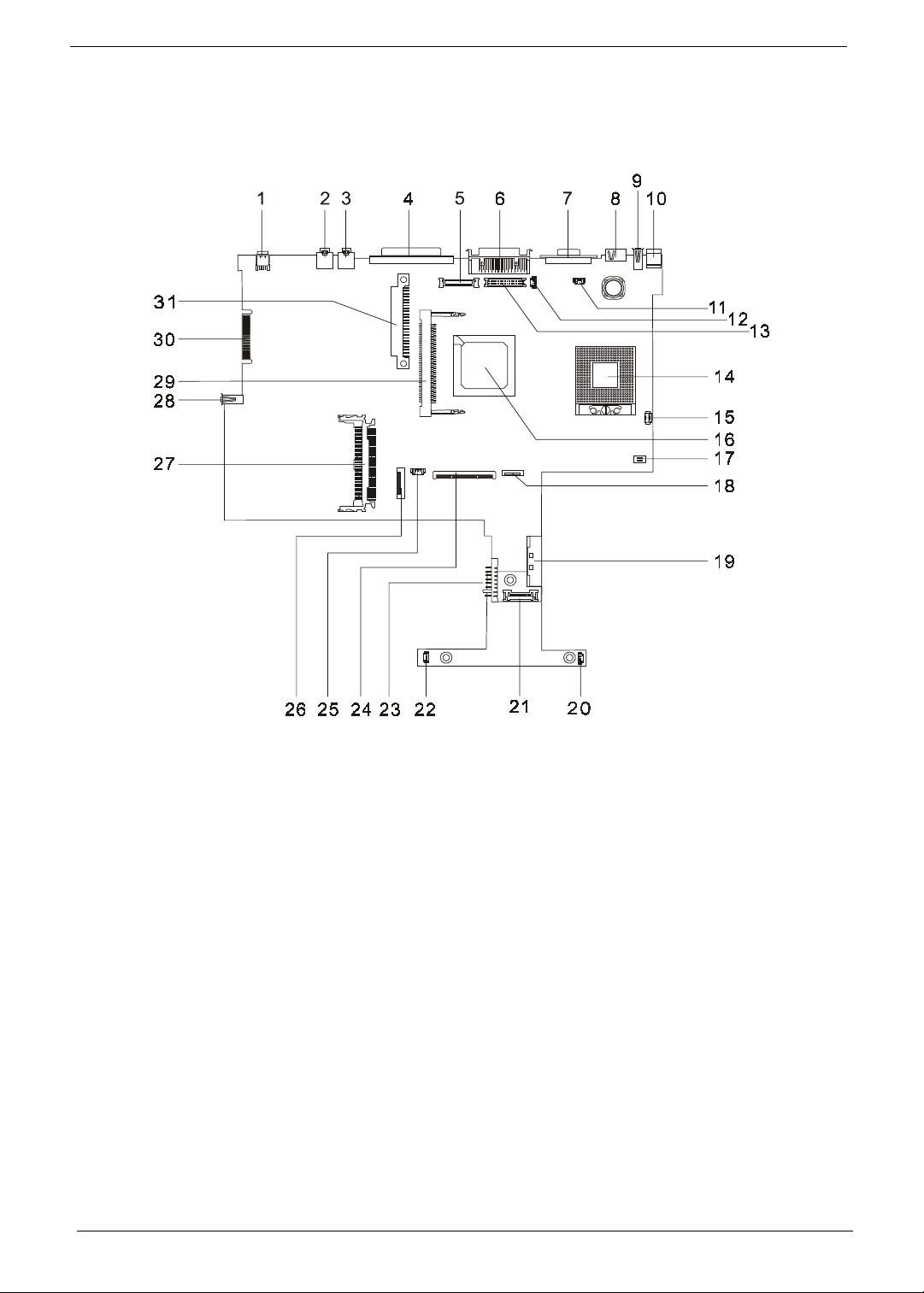
Top View
1 IEEE 1394 17 SW2 Setting
2 Line-in Port 18 Touch Pad Connector
3 Line-out Port 19 External CD/DVD-ROM Module Connector
4 Parallel Port 20 Speaker Connector
5 LCD Coaxial Cable Connector 21 Daughter Board Connector (on main board, under
daughter board)
6 Port Replicator 22 Speaker Connecto r
7 CRT Connector 23 Battery Connector
8 TV-out Port 24 Keyboard Connector
9 USB Port 25 RTC Battery Connector
10 DC-in Port 26 Cardbus/SmartCard Socket
11 LCD Cover Switch Connector 27 Cardbus connect or
12 Microphone-in Port 28 USB Port
13 LED/Inverter Board Connector 29 Mini PCI Connector
14 CPU Socket 30 Golden Finger
15 FAN Connector 31 HDD Connector
16 North Bridge
Chapter 1 5
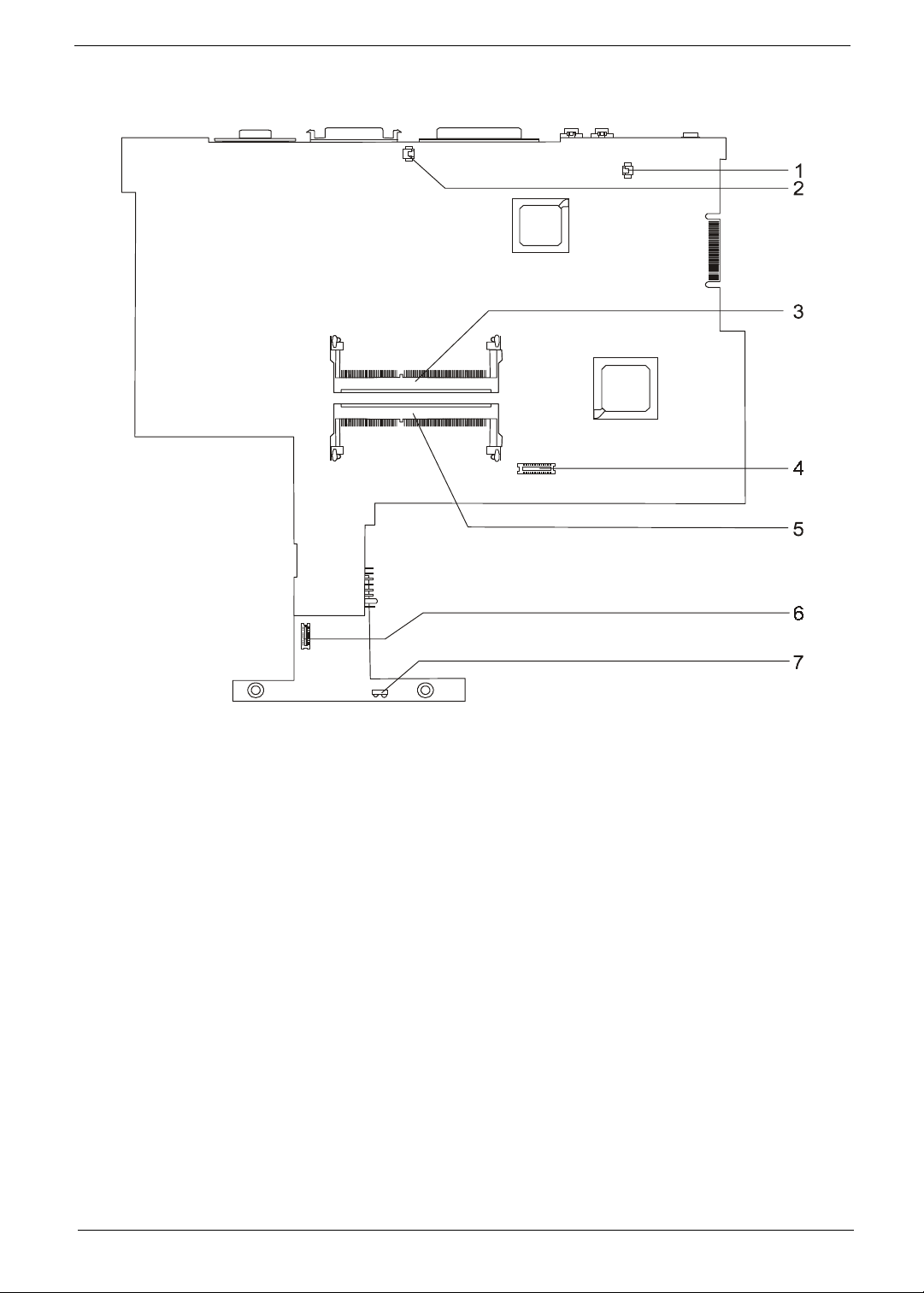
Bottom View
1 Modem Connector 5 DIMM socket 2
2 Modem Connector 6 RF Module Connector
3 DIMM Socket 1 7 FIR
4 Modem Board Socket
6 Chapter 1
Outlook View
A general introduction of ports allow you to connect peripheral devices, as you would with a desktop PC.
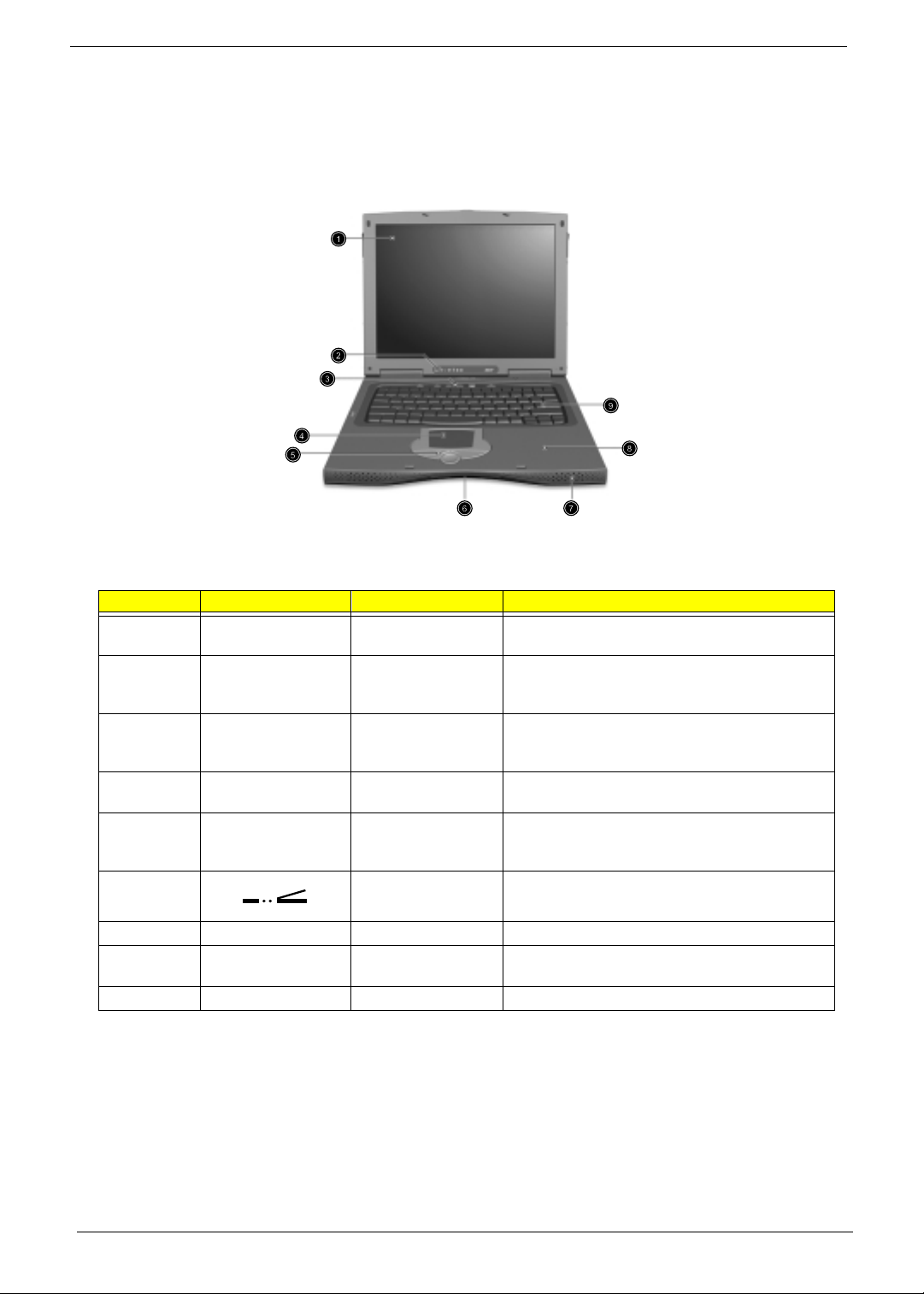
Front View
# Icon Item Description
1 Display screen Also called LCD (liquid-crystal display), diplays
computer output.
2 Status indicators LEDs (light-emitting diode) that turn on and off to
show the status of the computer, its functions and
components.
3 Launch Keys Special Keys for launching internet browser, email
program and frequently used programs. See
“Launch Keys” on page 17 for more details.
4 T ouchpad T ouch-sensitive pointing device which functions like a
computer mouse.
5 Click buttons (left,
center and right)
The left and right buttons function like the left and
right mouse buttons; the center button serves as a 4
way scroll button.
6 Infrared port Interfaces with infrared devices (e.g., infrared printer,
IR-aware computer).
7 Speaker Outputs sound
8 Palmrest Comfortable support area for your hands when you
use the computer.
9 Keyboard Inputs data into your computer.
Chapter 1 7
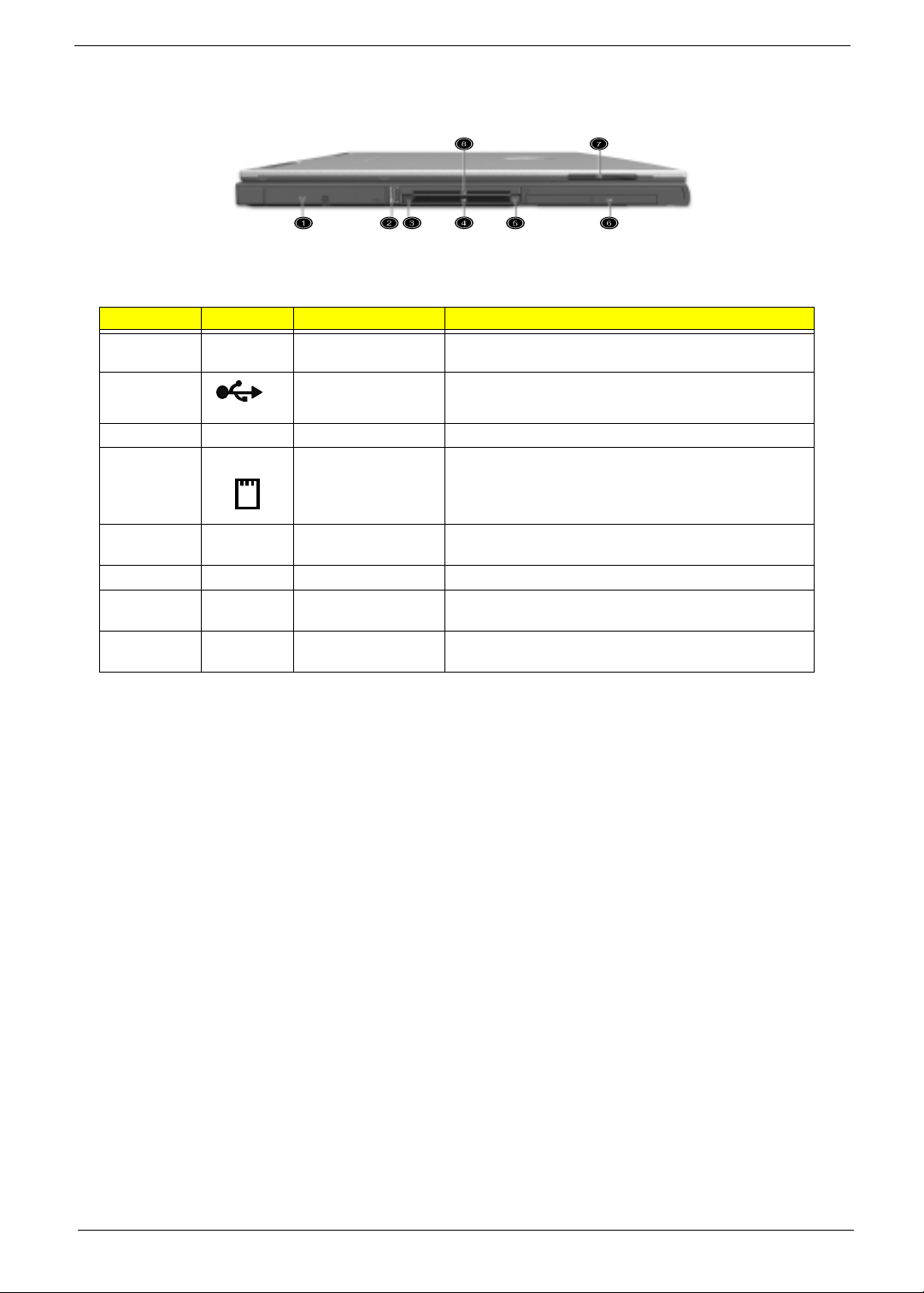
Left Panel
# Icon Item Description
1 Hard Disk Bay Houses the computer’s removable hard disk (secured by a
screw).
2 USB port Connect to Universal Serial Bus devices (e.g., USB mouse,
USB camera).
3 PC Card Eject buttons Eject the selected PC Card from the slot.
4 PC Card slot Accept one type III or 16-bit PC Card or 32-bit CardBus PC
Card.
5 Smart Card Eject
button
Ejects the SmartCard from the slot.
6 Battery bay Houses the computer’s battery pack.
7 Video capture kit slot Accepts the video capture kit option on the left side of the
computer.
8 Smart Card Slot Slot for Smart Card interface with pre-boot authentication
systems.
8 Chapter 1
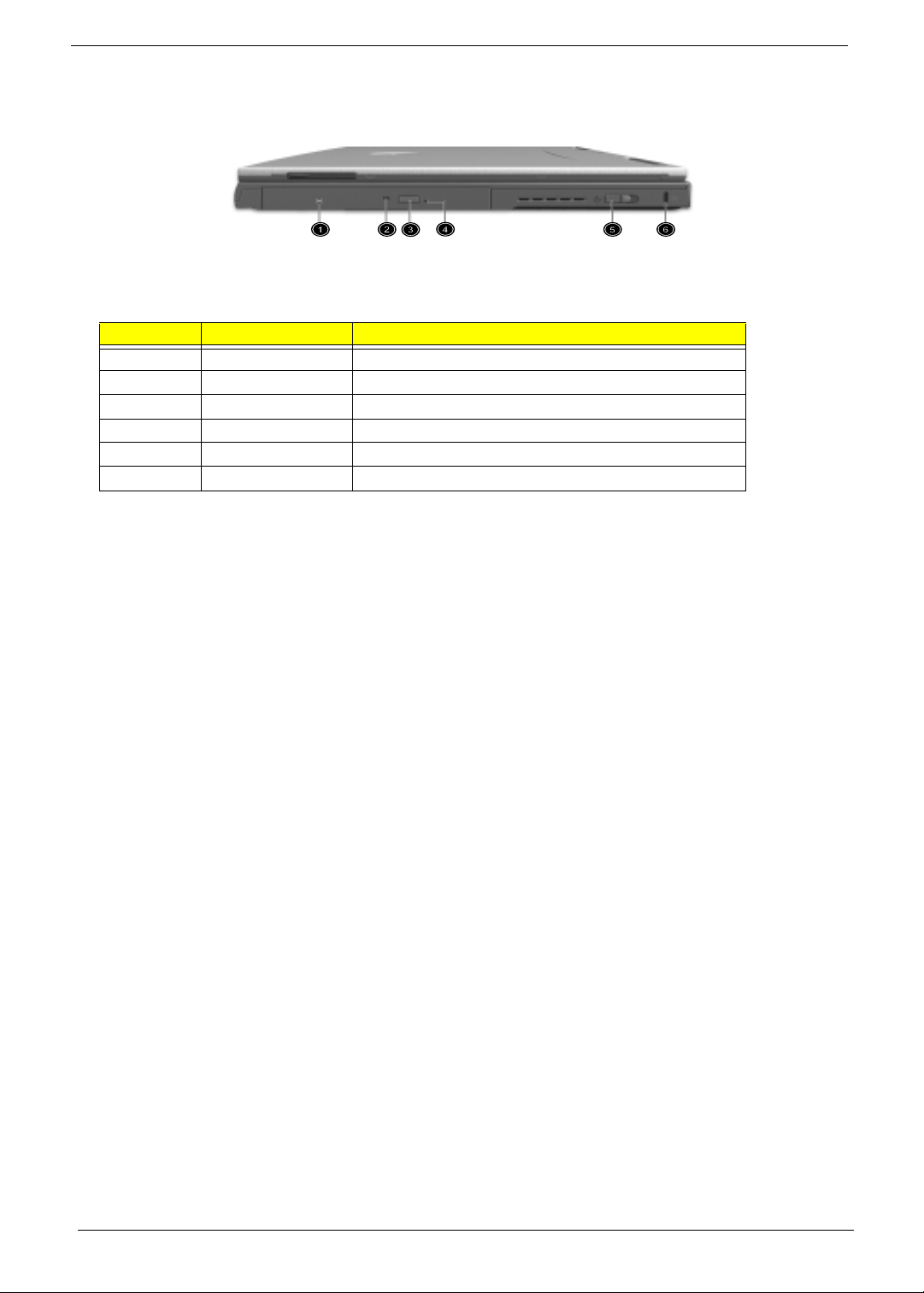
Right Panel
NOTE:
The positions of the AcerMedia indicator, eject button and emergency eject hole may differ depending
on hte optical drive module installed.
# Item Description
1 AcerMedia drive bay Houses a removable media drive module.
2 AcerMedia indicator Lights up when the AcerMedia drive is active.
3 Eject button Ejects the drive tray.
4 Emergency eject slot Ejects the drive tray when the computer is turned off.
5 Power switch Turns on the computer power.
6 Security keylock Connects to a Kensington-compatible computer security lock.
Chapter 1 9
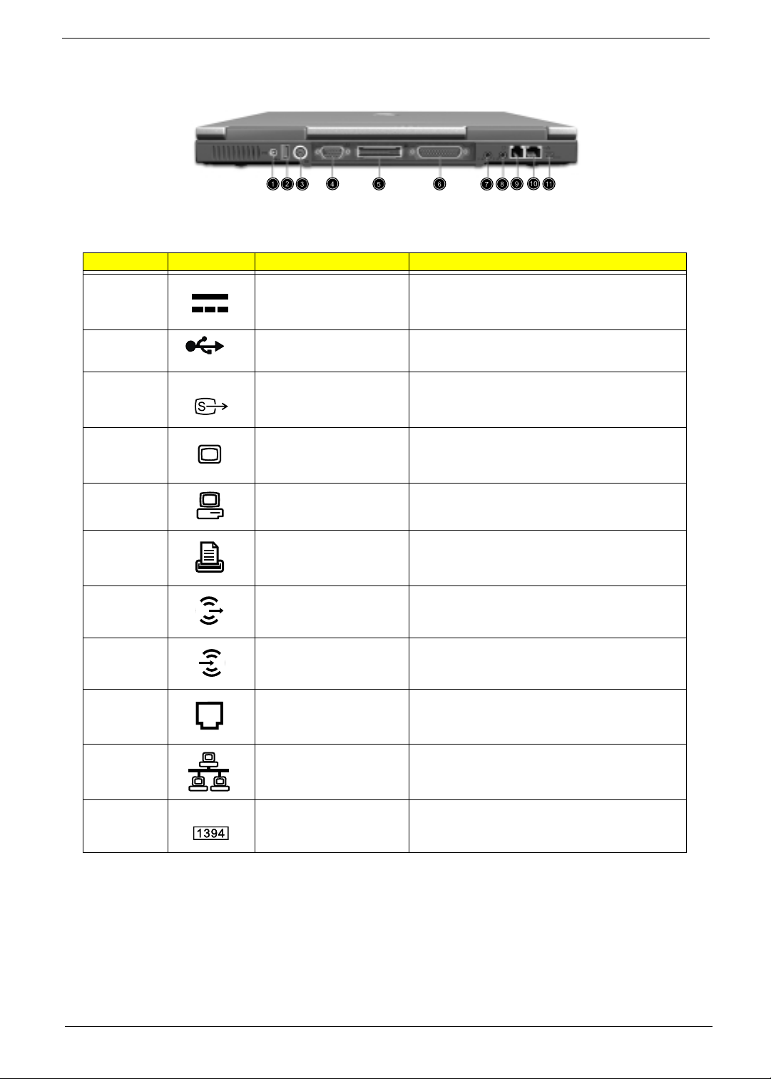
Rear Panel
# Icon Item Description
1 Power jack Connects to an AC adapter
2 USB ports (two) Connect to Universal Serial Bus devices (e.g., USB
mouse, USB camera).
3 S-video port Connects to a television or display device with S-
video input.
4 External display port Connects to a display device (e.g., external monitor,
LCD projector) and displays up to 16.7 million colors
at 1400x1050 resolution.
5 Easy Link Port/ Replicator
Port
I/O replicator for EasyPort expansion devices.
6 Parallel port Connects to a parallel device (e.g., parallel printer).
7 Speaker/Headphone-out
jack
Connects to audio line-out devices (e.g., speakers,
headphones).
8 Line-in jack Accepts audio line-in devices (e.g., audio CD player,
stereo walkman).
9 Modem jack Connects to a phone line.
10 Network jack Connects to an Ethernet 10/100-based network
11 IEEE 1394 Port Connects to IEEE 1394 devices.

10 Chapter 1
Bottom Panel
NOTE:
*: Do not cover or obstruct the opening of the fan.
# Icon Item Description
1 Cooling fan Helps keep the computer cool*.
2 AcerMedia bay release latch Unlatches the AcerMedia drive for removal or swapping.
3 AcerMedia bay Houses an AcerMedia drive module.
4 Personal identification slot Insert a business card or similar-sized identification card to
personalize your computer.
5 Battery release latch Unlatches the battery to remove the battery pack.
6 Battery bay Houses the computer’s battery pack.
7 Memory compartment Houses the computer’s main memory.
8 Hard disk bay Houses the computer’s hard disk. (Secured by a screw)
9 Hard disk protector Protects the hard disk from accidental bumps and vibration.
Chapter 1 11
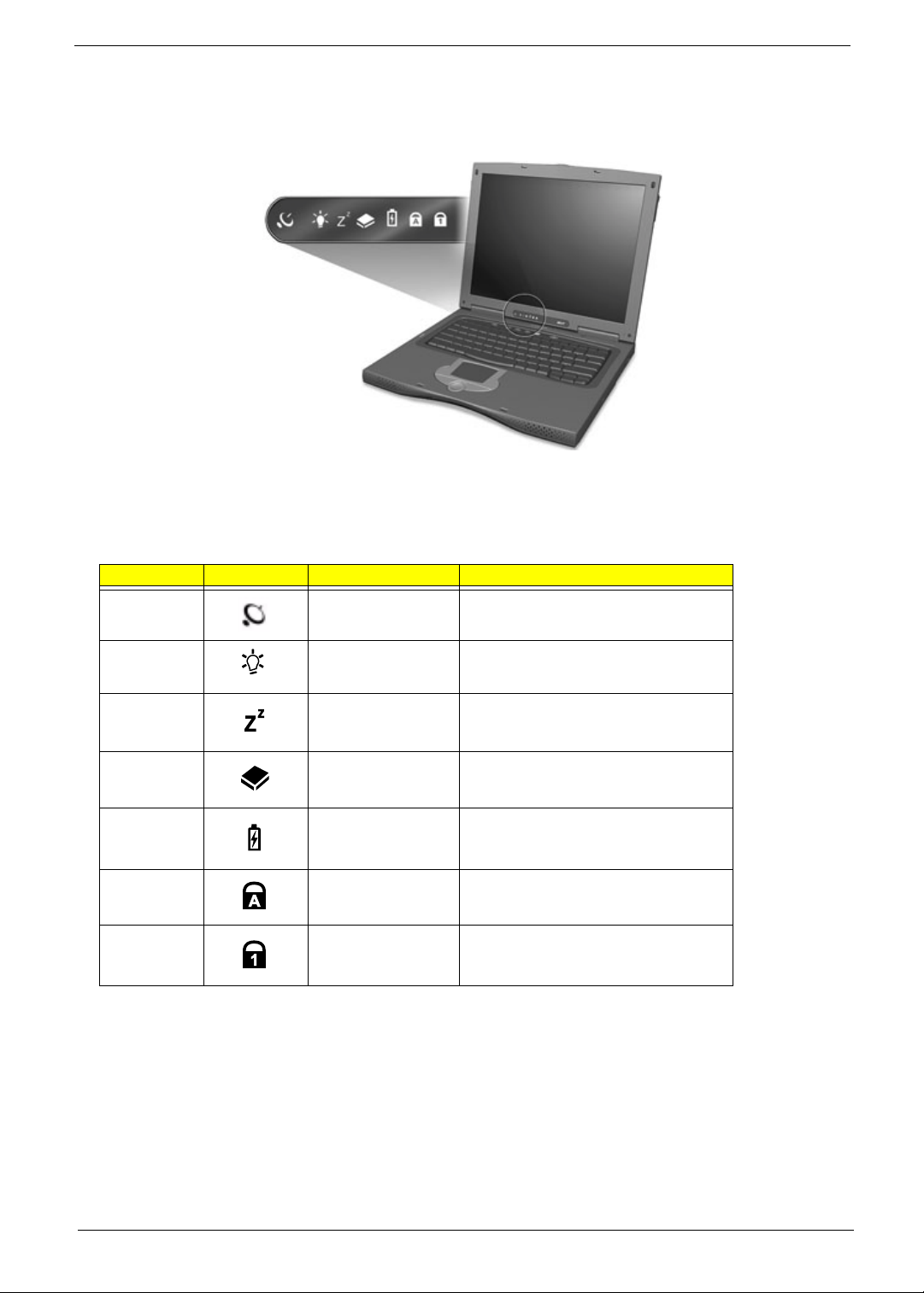
Indicators
The computer has seven easy-to-read status icons on the right of the display screen.
The Power and Sleep status icons are visible even when you close the display cover so you can see the status
of the computer while the cover is closed.
# Icon Function Description
1 Wireless
Communication
Lights when the Blue-Tooth/Wireless LAN
capabilities are enabled.
2 Power Lights when the computer is on.
Blinks when a battery-low condition occurs.
3 Sleep Lights when the computer enters Standby
mode and blinks when it enters into or
resumes from hibernation mode.
4 Media Activity Lights when the floppy drive, hard disk or
AcerMedia drive is active.
5 Battery Charge Lights when the battery is being charged.
6 Caps Lock Lights when Caps Lock is activated.
7 Num Lock Lights when Num Lock is activated.
12 Chapter 1
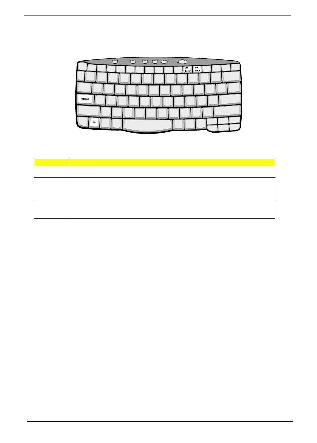
Lock Keys
The keyboard has three lock keys which you can toggle on and off.
Lock Key Description
@
@@
@
When
@
@@
@
is on, all alphabetic characters typed are in uppercase.
]
]]
]
(Fn-F11)
When
]
]]
]
is on, the embedded keypad is in numeric mode. The keys function as a calculator
(complete with the arithmetic operators +, -, *, and /). Use this mode when you need to do a lot of
numeric data entry. a better solution would be to connect an external keypad.
[
[[
[
(Fn-F12)
When
[
[[
[
is on, the screen moves one line up or down when you press the up or down arrow
keys respectively.
[
[[
[
does not work with some applications.
Chapter 1 13
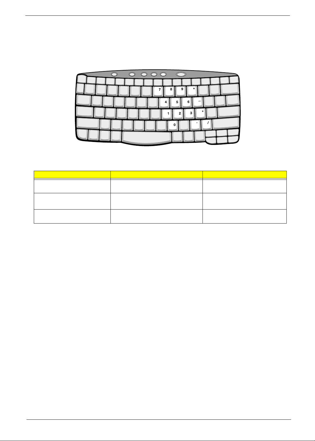
Embedded Numeric Keypad
The embedded numeric keypad functions like a desktop numeric keypad. It is indicated by small characters
located on the upper right corner of the keycaps. To simplify the keyboard legend, cursor-control key symbols
are not printed on the keys.
NOTE:
If an external keyboard or keypad is connected to the computer, the
]
]]
]
feature automatically shifts
from the internal keyboard to the external keyboard or keypad.
Desired Access Num Lock On Num Lock Off
Number keys on embedded
keypad
Type numbers in a normal manner.
Cursor-control keys on embedded
keypad
Hold
j
jj
j
while using cursor-control
keys.
Hold Fn while using cursor-control
keys.
Main keyboard keys Hold Fn while typing letters on embedded
keypad.
Type the letters in a normal manner.
14 Chapter 1
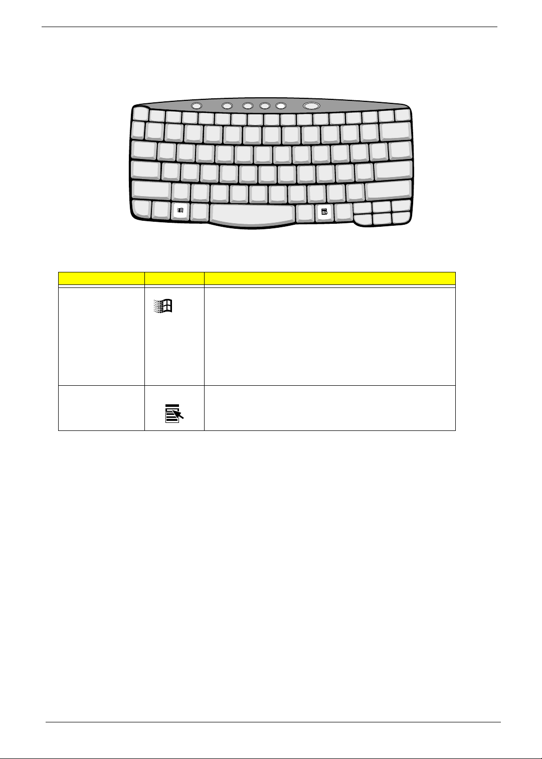
Windows Keys
The keyboard has two keys that perform Windows-specific functions.
Key Icon Description
Windows logo key Start button. Combinations with this key perform shortcut functions.
Below are a few examples:
!
+ Tab (Activates next taskbar button) Windows
+ E (Explores My
Computer)
!
+ F (Finds Document)
!
+ M (Minimizes All)
j
jj
j
+
!
+ M (Undoes Minimize All)
!
+ R (Displays the Run...dialog box)
Application key Opens a context menu (same as a right-click).
Chapter 1 15
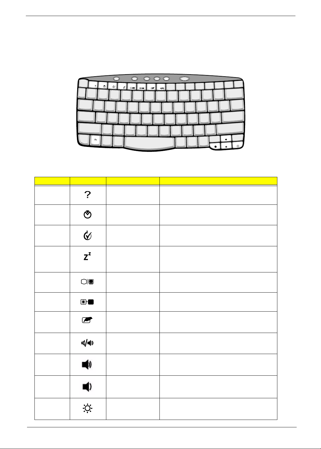
Hot Keys
The computer employs hot keys or key combinations to access most of the computer’s controls like screen
contrast and brightness, volume output and the BIOS Utility.
To activate hot keys, press and hold the
Fn
key before pressing the other key in the hot key combination.
Hot Key Icon Function Description
Fn-F1 Hot key help Displays a list of the hotkeys and their functions.
Fn-F2 Setup Accesses the notebook’s configuration utility.
Fn-F3 Power Management
Scheme Toggle
Switches the power management scheme used by the
computer (function available if supported by operating
system).
Fn-F4 Sleep Puts the computer in Sleep mode, which can be
defined via the advanced section of the Power
Management Properties in the Windows Control
Panel.
Fn-F5 Display toggle Switches display output between the display screen,
external monitor (if connected) and both the display
screen and external monitor.
Fn-F6 Screen blank Turns the display screen backlight off to save power.
Press any key to return.
Fn-F7 Touchpad toggle Turns the internal touchpad on and off.
When you connect an external PS/2 mouse, the
computer automatically disables the touchpad.
Fn-F8 Speaker toggle Turns the speakers on and off; mutes the sound.
Fn-up Volume up Increases the speaker volume.
Fn-dow n Volume down Decreases the speaker volume.
Fn-
→
Brightness up Increases the screen brightness.

16 Chapter 1
Fn-
←
Brightness down Decreases the screen brightness.
Hot Key Icon Function Description

Chapter 1 17
Launch Keys
Located at the top of the keyboard are five buttons. These buttons are called launch keys. They are
designated as P1, P2, P3, Mail button and Web browser button. By default, buttons P1and P2 are users
programmable. The mail button is used to launch the mail application. The LED of the mail button will flash
when the user has received an incoming email. The P3, by default is used to launch a multimedia application
that came bundled with your system. The web browser button, by default is used to launch your internet
browser.

18 Chapter 1
Touchpad
The built-in touchpad is a PS/2-compatible pointing device that senses movement on its surface. This means
the cursor responds as you move your finger on the surface of the touchpad. The central location on the
palmrest provides optimum comfort and support.
NOTE:
When using an external USB or serial mouse, you can press Fn +
r
rr
r
to disable the touchpad. If you
are using an external PS/2 mouse, the touchpad is automatically disabled.
Touchpad Basics
The following items teach you how to use the touchpad:
!
Move your finger across the touchpad to move the cursor.
!
Press the left (1) and right (3) buttons located on the edge of the touchpad to do selection and
execution functions. These two buttons are similar to the left and right buttons on a mouse.
Tapping on the touchpad produces similar results.
!
Use the center (2) button (top and bottom) to scroll up or down a page. This button mimics your
cursor pressing on the right scroll bar of Windows applications.
Chapter 1 19
NOTE: Keep your fingers dry and clean when using the touchpad. Also keep the touchpad dry and clean.
The touchpad is sensitive to finger movements. Hence, the lighter the touch, the better the response.
Tapping harder will not increase the touchpad’s responsiveness.
Function
Left
Button
Right
Button
Center
Buttons
Tap
Execute Click twice
quickly
Tap twice (at the same speed as
double-clicking a mouse button)
Select Click once Tap once
Drag Click and hold,
then use finger to
drag the cursor
on the touchpad
Tap twice (at the same speed as
double-clicking a mouse button)
then hold finger to the touchpad
on the second tap and drag the
cursor
Access context
menu
Click once
Scroll Click and hold
the up/down
button

20 Chapter 1
Hardware Specifications and Configurations
Processor
Item Specification
CPU type Intel Pentium IV 1.5/1.6/1.7 GHz processor with 512KB L2 on-die Cache
CPU package Micro-FCPGA package
CPU core voltage 1.40V/1.15V
CPU I/O voltage 1.25V
BIOS
Item Specification
BIOS vendor Phoenix
BIOS Version V 4.0 R6.1
BIOS ROM type Flash ROM
BIOS ROM size 512KB
BIOS package 32-pin TSOP
Supported protocols ACPI 1.0b, APM 1.2, PC Card 95, SM BIOS 2.3, EPP/IEEE 1284, ECP/
IEEE 1284 1.7 & 1.9, IrDA, PCI 2.2, PnP 1.0a, DMI 2.0, PS/2 keyboard and
mouse, USB, VESA VGA BIOS, DDC-2B, CD-ROM bootable, Windows
keyboard Microsoft Simple Boot Flag
BIOS password control Set by switch, see SW2(SW1) setting
Second Level Cache
Item Specification
Cache controller Built-in CPU
Cache size 512KB
1st level cache control Always enabled
2st level cache control Always enabled
Cache scheme control Fixed in write-back
System Memory
Item Specification
Memory controller Built-in Intel Amador-M
Onboard memory size 0MB
DIMM socket number 2 sockets (2 banks)
Supports memory size per socket 512MB
Supports maximum memory size 1024MB
Supports DIMM type Synchronous DDR
Supports DIMM Speed 266 MHz
Supports DIMM voltage 3.3V
Supports DIMM package 200-pin soDIMM
Memory module combinations You can install memory modules in any combinations as long as they
match the above specifications.
Loading...