

Acer Travelmate 230, Travelmate 280 Service Manual

TravelMate 230/ 280
Service Guide
PART NO.: 49.46W01.001
PRINTED IN TAIWAN

Revision History
Please refer to the table below for the updates made on HP Lapin service guide.
Date Chapter Updates
01/20/2003 Cover page Correct typo on page II
Dual high quality stereo speakers on page 2
Modify item 3 media activity on page 12
Supports memory size per socket: 512MB on page 19
USB Compliancy Level: USB 2.0 on page 25
Chapter 2 Modify Flash BIOS procedures
Delete "Removing HDD password procedures"
Chapter 3 Mark the size of the flat-bladed screwdriver and hexed
Chapter 4 Modify wording: If an error occurs with the internal diskette
Chapter 5 Modify Switch Setting
02/08/2003 Chapter 1 Delete dual display feature
04/14/2003 Chapter 1 Delete RS-232 serial port connectivity feature
screwdriver
Correct the disassembly procedure of HDD module.
drive, first turn off the power and then reconnect the
diskette connector to the system board.
II

Copyright
Copyright © 2003 by Acer Incorporated. All rights reserved. No part of this publication may be reproduced,
transmitted, transcribed, stored in a retrieval system, or translated into any language or computer language, in
any form or by any means, electronic, mechanical, magnetic, optical, chemical, manual or otherwise, without
the prior written permission of Acer Incorporated.
Disclaimer
The information in this guide is subject to change without notice.
Acer Incorporated makes no representations or warranties, either expressed or implied, with respect to the
contents hereof and specifically disclaims any warranties of merchantability or fitness for any particular
purpose. Any Acer Incorporated software described in this manual is sold or licensed "as is". Should the
programs prove defective following their purchase, the buyer (and not Acer Incorporated, its distributor, or its
dealer) assumes the entire cost of all necessary servicing, repair, and any incidental or consequential
damages resulting from any defect in the software.
Intel is a registered trademark of Intel Corporation.
Pentium and Pentium II/III are trademarks of Intel Corporation.
Other brand and product names are trademarks and/or registered trademarks of their respective holders.
III

Conventions
The following conventions are used in this manual:
Screen messages Denotes actual messages that appear
on screen.
NOTE Gives bits and pi eces of additional
information related to the current
topic.
WARNING Alerts you to any dam age that might
result from doing or not doing specific
actions.
CAUTION Gives precautionary measures to
avoid possibl e hardware or software
problems.
IMPORTANT Reminds you to do specific actions
relevant to the accom plishment of
procedures.
IV

Preface
Before using this i nformation and the product it supports, please re ad the f oll owing general inform ati on.
1. This Service Guide provides you with all technical in for m ation relating to the BASIC CONFIGURATION
decided for Acer "global " product offering. To better fit local market requirements and enhance pro duct
competitiv eness, your regional office MAY have decided to exten d the functionality of a machine (e.g.
add-on card, modem, or extr a me mo ry capability). The se LOCALIZED FEATURES will NOT be covered
in this generic service guide. In such cases, please contact your regional of fices or the responsible
personnel/channel to provide you with further technical details.
2. Please note WHEN ORDERING FRU PARTS, that you should check the most up-to-date infor m ati on
available on you r reg ional web or channel. If, for whatev er reason, a part number change is made, it will
not be noted in the printed Serv ic e Guide. For ACER AUTHORIZED SERVICE PROVIDERS, your Acer
office may have a DIFFERENT part number code to those giv en in t he FRU li st of thi s pri nted Service
Guide. You MUST use the list provided by your regional Acer office to order FRU pa rts for repair and
service of customer machines.
V

VI

T a ble of Contents
Chapter 1 System Introductio n 1
Features . . . . . . . . . . . . . . . . . . . . . . . . . . . . . . . . . . . . . . . . . . . . . . . . . . . . . . . .1
System Block Diagram . . . . . . . . . . . . . . . . . . . . . . . . . . . . . . . . . . . . . . . . . . . . .4
Board Layout . . . . . . . . . . . . . . . . . . . . . . . . . . . . . . . . . . . . . . . . . . . . . . . . . . . .5
Panel . . . . . . . . . . . . . . . . . . . . . . . . . . . . . . . . . . . . . . . . . . . . . . . . . . . . . . . . . . .7
Indicators . . . . . . . . . . . . . . . . . . . . . . . . . . . . . . . . . . . . . . . . . . . . . . . . . . . . . .12
Keyboard . . . . . . . . . . . . . . . . . . . . . . . . . . . . . . . . . . . . . . . . . . . . . . . . . . . . . .13
Hot Keys . . . . . . . . . . . . . . . . . . . . . . . . . . . . . . . . . . . . . . . . . . . . . . . . . . . . . . .15
Hardware Specifications and Configurations . . . . . . . . . . . . . . . . . . . . . . . . . . .18
Chapter 2 System Utilities 33
BIOS Setup Utility . . . . . . . . . . . . . . . . . . . . . . . . . . . . . . . . . . . . . . . . . . . . . . . .33
Multi-Boot Menu . . . . . . . . . . . . . . . . . . . . . . . . . . . . . . . . . . . . . . . . . . . . . . . . .35
Boot Options . . . . . . . . . . . . . . . . . . . . . . . . . . . . . . . . . . . . . . . . . . . . . . . . . . . .49
BIOS Flash Utility . . . . . . . . . . . . . . . . . . . . . . . . . . . . . . . . . . . . . . . . . . . . . . . .52
System Utility Diskette . . . . . . . . . . . . . . . . . . . . . . . . . . . . . . . . . . . . . . . . . . . .53
System Diagnostic Diskette . . . . . . . . . . . . . . . . . . . . . . . . . . . . . . . . . . . . . . . .54
Chapter 3 Machine Disassembly and Replacement 57
General Information . . . . . . . . . . . . . . . . . . . . . . . . . . . . . . . . . . . . . . . . . . . . . .58
Disassembly Procedure Flowchart . . . . . . . . . . . . . . . . . . . . . . . . . . . . . . . . . . .59
Removing the Battery . . . . . . . . . . . . . . . . . . . . . . . . . . . . . . . . . . . . . . . . . . . . .62
Removing the Hard Disk Drive Module . . . . . . . . . . . . . . . . . . . . . . . . . . . . . . . .63
Removing the Memory Module . . . . . . . . . . . . . . . . . . . . . . . . . . . . . . . . . . . . . .65
Removing the Modem Board . . . . . . . . . . . . . . . . . . . . . . . . . . . . . . . . . . . . . . .66
Disassembling the LCD . . . . . . . . . . . . . . . . . . . . . . . . . . . . . . . . . . . . . . . . . . .68
Disassembling the Main Unit . . . . . . . . . . . . . . . . . . . . . . . . . . . . . . . . . . . . . . .79
System Upgrade Procedure . . . . . . . . . . . . . . . . . . . . . . . . . . . . . . . . . . . . . . . .91
Chapter 4 Troubleshootin g 93
System Check Procedures . . . . . . . . . . . . . . . . . . . . . . . . . . . . . . . . . . . . . . . . . 94
Power-On Self-Test (POST) Error Message . . . . . . . . . . . . . . . . . . . . . . . . . . .98
Index of Error Messages . . . . . . . . . . . . . . . . . . . . . . . . . . . . . . . . . . . . . . . . . . .99
Index of Symptom-to-FRU Error Message . . . . . . . . . . . . . . . . . . . . . . . . . . . . 102
Intermittent Problems . . . . . . . . . . . . . . . . . . . . . . . . . . . . . . . . . . . . . . . . . . . .1 05
Undetermined Problems . . . . . . . . . . . . . . . . . . . . . . . . . . . . . . . . . . . . . . . . . .106
Index of Phlash16 Error Message . . . . . . . . . . . . . . . . . . . . . . . . . . . . . . . . . .107
Index of PQA Diagnostic Error Code, Message . . . . . . . . . . . . . . . . . . . . . . . .109
Chapter 5 Jumper and Connector Locations 111
Top View . . . . . . . . . . . . . . . . . . . . . . . . . . . . . . . . . . . . . . . . . . . . . . . . . . . . . .111
Bottom View . . . . . . . . . . . . . . . . . . . . . . . . . . . . . . . . . . . . . . . . . . . . . . . . . . .1 13
Chapter 6 FRU (Field Replaceable Unit) List 115
TravelMate 230 Exploded Diagram . . . . . . . . . . . . . . . . . . . . . . . . . . . . . . . . .116
TravelMate 280 Exploded Diagram . . . . . . . . . . . . . . . . . . . . . . . . . . . . . . . . .125
Appendix A Model Definition and Configuration 135
Model Number Definition . . . . . . . . . . . . . . . . . . . . . . . . . . . . . . . . . . . . . . . . .135
Appendix B Test Com patible C ompon en ts 137
Microsoft Windows XP Environment Test . . . . . . . . . . . . . . . . . . . . . . . . . . . . .138
Microsoft Windows 2000 Environment Test . . . . . . . . . . . . . . . . . . . . . . . . . . .142
Microsoft Windows 98 Environment Test . . . . . . . . . . . . . . . . . . . . . . . . . . . . .146
VII

Table of Contents
Appendix C Online Support Information 151
Index 153
VIII

System Introduction
Features
This computer was designed with the user in mind. Here are just a few of its many features:
Performance
T Intel
T Intel
T 64-bit memory bus
T Two 200-pin DDR-DRAM with each supporting 128MB/ 256MB/ 512MB, upgradable to the total
T Built-in floppy diskette drive and Hard diskette drive
T High-capacity, Enhanced-IDE hard disk
T Simultaneous LCD and CRT display
T Smart Lithium-Ion battery pack
T Power management system with ACPI (Advanced Configuration Power Interface)
T Plug and Play Feature
®
Mobile Celeron Pentium® 4 series processors from 1.6G up tp 2.0G with 512KB cache
(TravelMate 230)
®
Mobile Northwood Pentium® 4 series processors from 1.6G up tp 2.4G with 512KB cache
(TravelMate 280)
maximum of 1024MB with SODIMM modules, supporting PC1600/2100 .
Chapter 1
Multimedia
T 16-bit high-fidelity AC’97 stereo audio with 3D sound and wavetable synthesizer
T Built-in dual speakers
T High- speed CD-ROM, DVD-ROM, or DVD/ CD-R/RW drive
Connectivity
T 84/85/88 key keyboard, which is PC/AT keyboard compatible.
T Four Universal Serial Bus (USB) 2.0 Ports (Two ports optional)
T Bluetooth (Optional)
T Two IEEE 1394 ports (optional)
T Built-in V.90 and V.92 RJ-11 56Kbps fax/modem
T Onboard 10/100 Mbps Ethernet LAN Support
T Upgradeable memory and hard disk
T Mini PCI interface 802.11b/ 802.11a+b Module (optional)
T ECP Compliant parallel port.
Multimedia
T All-in-one design (CD-ROM, floppy disk drive, hard disk drive)
T Sleek, smooth and stylish design
T Full-sized keyboard
T Ergonomically centered touchpad pointing device with Internet scroll key
Chapter 1 1

Expansion
I/O Po rts
Display
K
One CardBus PC Card (formerly PCMC IA) Type III slot.
K
Upgrageable memory and hard disk
K
One VGA port, I2 C compatible (Op tional)
K
One DC-in port (AC adapter)
K
Dual high quality stereo speakers
K
One line-in
K
One line-out
K
One CardBus type III slot (3.3V, 5V, 12V support)
K
Four USB ports (2 ports optional)
K
Two IEEE 1394 ports (optional)
K
One ECP parallel port
K
One RJ-11 port
K
One RJ-45 jack
K
14.1” and 15” TFT LCD displaying 32-bit true-color at 1024x768 XGA resolution
K
3D capabilities
K
Supports other output display devices such as LCD projection panels for large audience
presentations
K
“Automatic LCD dim” feature that automatically decides the best sett ings for your display and
conserves power is activated when the system operates in Battery con dition.
Video performa n ce
4X AGP UMA video graphic accelerator with 8MB shared from syst em me mory wi th Intel 845GL to boost the
video performance.
Simultaneous display
The computer’s large display and multimedia capabilities are great for giving presentations. If you prefer, you
can also connect an external monitor when giving presentations. This computer has built-i n A GP and VGA
display syst em to support simultaneous LCD and CRT displ ay. Simultaneous displ ay allows you to contr ol the
presentation from your computer and at the same time face your audience. You can also conne ct other output
display devices such as LCD projection panels for large-audience presentations.
Dual Display
The computer’s unique graphics chip takes advantage of Windows XP’s multi-display capability, allowing you
to extend your deskt op to an external displ ay device, such as an external mon it or projector. With this feature
enabled, you can move program windows to/from the computer LCD and the external monitor.
Power m a nagemen t
The power management syste m inco rporates an "au tomati c LCD dim" feat ure that autom atic ally d ims the LCD
when the computer is powered by a battery pack to conser ve battery power. See “Power Management” on
page 28 for more information on power management feat ures.
Chapter 1 2

Opening and closing the display
To open the displ ay, slide the display cover latch to the right and l if t up the cover. Then tilt it to a comfortable
viewing posi ti on. The computer empl oys a m icroswitch tha t turns off the display (and enters standby mode) to
conserve power when you close the display cover, and tur ns it back on when you open the display cover.
NOTE: If an external moni tor is connected, the comp uter turns off the display (but does not enter standby
mode) when you close the display cover.
To close the di splay cover, fold it down gently until the display cover l a tch clicks into place.
WARNING: To avoi d dam aging the display, do not slam it when you close it. Also, do not place any object on
top of the computer when the display is closed.
3 TravelMate 230/ 280

System Block Diagram
Mobile CPU
Mobile CPU
P4-M N orthwood
P4-M N orthwood
P4-M Celeron
P4-M Celeron
HOST BUS 100MH z
HOST BUS 100MH z
Brookdale-GL
Brookdale-GL
HUB I/F 66MHz
HUB I/F 66MHz
INT . M IC
INT . M IC
MIC IN
MIC IN
Line In
Line In
CLK GEN
CLK GEN
ICS 94239
ICS 94239
DDR*2
DDR*2
DDR*2
266M H z
266M H z
266M H z
AC ‘97
AC ‘97
CODEC
CODEC
CS4299XQ
CS4299XQ
AC-Link
AC-Link
MCH
MCH
EXTERNAL
EXTERNAL
SPEE D ST E P
SPEE D ST E P
CIRCUIT
CIRCUIT
G768D
G768D
RGB
RGB
DVO LVDS
DVO LVDS
Chrontel
Chrontel
7019
PCI BUS
PCI BUS
7019
CARDBUS
CARDBUS
OZ 69 12
OZ 69 12
MINI PCI
MINI PCI
802.11
802.11
Dual
Dual
Channel
Channel
CRT
CRT
CONN
CONN
LCD
LCD
PWR SW
PWR SW
OZ 2211 S
OZ 2211 S
CARDBUS
CARDBUS
ONE SLOT
ONE SLOT
VR
VR
Line Out
Line Out
AUDIO
AUDIO
BOARD
BOARD
INT. SPKR
INT. SPKR
OP AMP
OP AMP
TPA020 2
TPA020 2
MODEM
MODEM
MDC Card
MDC Card
PIDE
PIDE
HDD
HDD
IC H 4
IC H 4
SIDE
SIDE
CD
CD
ROM
ROM
USB
USB
USB
USB
BT.
BT.
AGERE 1394
AGERE 1394
FW 3230 5
FW 3230 5
LAN
LAN
REALTEK
REALTEK
8100BL
8100BL
NS SIO
NS SIO
PC87392
PC87392
PRN
PRN
Port
Port
FDD
FDD
1394
1394
CONN
CONN
LPC BUS
LPC BUS
SER.
SER.
RES
RES
KBC
KBC
M38859
M38859
M38857
M38857
TRACK
TRACK
POINT
POINT
NARI
NARI
FWH 4MB
FWH 4MB
SIOC32
SIOC32
SOIC40
SOIC40
IN T KB
IN T KB
LPC
LPC
DEBUG
DEBUG
CONN.
CONN.
Chapter 1 4
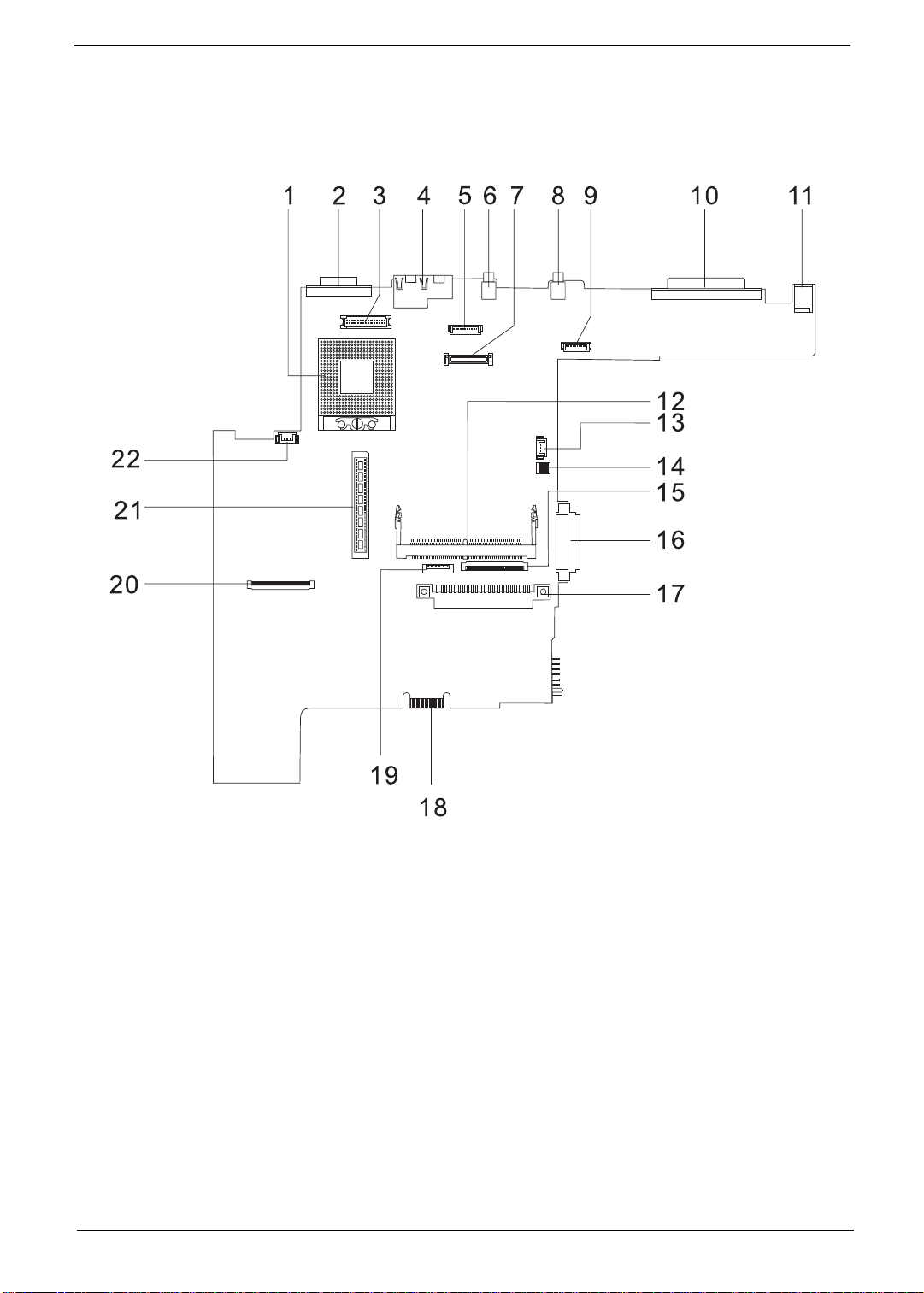
Board Layout
Top View
PCB No. 02217-SB
1 CPU Socket 12 Mini-PCI Connector
2 CRT Port 13 RTC Battery Connector
3 Inverter Connector 14 SW1 Setting (Please see Chapter 5 for details)
4 RJ45 + RJ11 15 Inte r na l Key board Cabl e C on ne ctor
5 Bluetooth Connector (Dummy) 16 CD-ROM Connector
6 USB Port 0 17 HDD Connector
7 LCD Coaxial C able Connector 18 Golden Finge r (or Debug Board)
8 USB Port 1 19 Touch Pad Cable Connector
9 Launch Cable Connector 20 FDD Connecto r
10 Parallel Port 21 CardBus Connector
11 DC-in Port 22 Fan Connector
5 TravelMate 230/ 280

Bottom View
1 Modem Cable Connector 7 Modem Connector
2 North Bridge (845-GL) 8 Battery Connector
3 DIMM Socket 1 9 CardBus Controller (OZ6912T)
4 Audio Board Connector 10 LAN Controller (RTL8100BL)
5 DIMM Socket 2 11 LVDS
6 South Bridge (ICH4)
Chapter 1 6

Panel
Ports allow you to connect peripheral devices to your computer as you woul d wit h a desktop PC.
Front Panel
# Item Description
1 Display scree n Also call ed LCD ( Li quid Cr ys t al D isp la y) , d is pl ay s c omput e r
output.
2 Status indicators LEDs (Light Emitting Diodes) that turn on and off to show
the status of the computer and its f unctions and
components.
3 Touchpad Touch-sensitive pointing device which functions like a
computer mouse.
4 Click button (left, center and right) The left and right buttons function like the left and right
mouse buttons, the center button serves as a scroll up/
down button.
5 Palmres t Comfor tab le sup po rt ar ea f or your han ds when yo u us e th e
6 Keyboard Inputs data into your computer.
7 Easy launch keys Buttons for launching frequently used programs.
computer.
7 TravelMate 230/ 280

Left Panel
# Icon Item/ Port Description
1 PCMCIA (PC card) Port Connects to one Type III 16-bit PC card or 32-bit
2 Eject button Eject PC cards from the card slots.
3 Floppy activity indicator LED (light-emitting diodes) that turn on and off
4 Speaker/ headphone-out jack Connects to audio line-out devices (e.g.,
CardBus PC Card.
when the flopp y is act ive.
speakers, head phones)
5 Li ne-in ja ck Accepts audio line-in devices (e .g., audio CD
player, stereo walkman).
6 Mi c rophone -in jack Accepts a mono/stereo condenser micropho ne.
7 Floppy dri v e Internal diskette drive, accepts 3.5-inch floppy
diskettes
8 Volume control Controls the volume of th e speakers.
9 Floppy disk eject but ton Push this butt on to eject the floppy disk
Chapter 1 8

Right Panel
# Icon Item/ Port Description
1 Battery bay Houses the computer’s battery pack.
2 Optical dri ve Houses rem o va ble optica l dr iv e mo du les.
3 LED indicator Lights up when the optical drive is active.
4 Eject button Ejects the compact disc from the drive.
5 Emergency eject sl ot Ejects the comp act discs when the computer
is turned off.
6 Securit y keylock Kensingt on-comp atible ke y-based computer
secur it y l o ck .
9 TravelMate 230/ 280

Rear Panel
# Icon Port Description
1 Power Jack Connects to an AC adapter
2 Parallel port Connects to a parallel device (e.g., parallel
3 USB port (two) Connects to any Universal Serial Bus
4 Modem jack Connects to the phone line
5 Network jack Connects to an Ethernet 10/100-based
6 Exter na l displa y por t Con ne cts to a d is pl ay de vi ce ( e. g. , ext e rnal
printer)
devices (e.g., USB mouse, USB camera).
network
monitor, LCD projector) and displays up to
64K colors at 1280x1024 resolution
Chapter 1 10

Bottom Panel
# Item Description
1 Batte ry bay Houses the computer’s battery pack.
2 Battery releas e latch Unlatches the battery to remove the battery pack.
3 Hard di sk bay Houses the co mputer’s hard disk (secured by a screw).
4 Memory compartment Houses th e computer’s main memory.
11 TravelMate 230/ 280

Indicators
The computer has six easy-to-read status icons on the right of the display screen.
The Power and S tandby status icons are visible even when you close the display cover so you can see the
status of th e computer while the cover is clos ed.
# Icon Function Description
1 Power Lights when the computer is on.
2 Sleep Lights when the computer enters Standby
3 Media Activity Lights when the floppy dr ive, hard disk or
4 Battery Charge Lights when the battery is being charged.
5 Caps Lock Lights when Caps Lock is activated.
6Num Lock
(Fn-F11)
mode and blinks when it enters into or
resumes from hibernation mode.
Media drive is active.
Lights when Numeric Lock is activated.
Chapter 1 12

Keyboard
The keyboard has full-sized keys and an embedded keypad, separate cursor keys, two Windows keys and
twelve function keys.
Special keys
Lock keys
The keyboard has three lock keys which you can toggle on and off.
Lock key Description
Caps Lock
When
@
is on, all alphabetic characters typed are in uppercase.
@
Num Lock (Fn-F11)
]
Scroll Lock (Fn-F12)
[
Embedded numeric keypad
The embedded numeri c keypad functions li ke a desktop numeric keypad. It is indicated by small characters
located on the upper right corner of the keycaps. To simplify the keyboard legend, cursor-control key sym bols
are not printed on the keys.
When
]
is on, the embedded keypad is in numeric mode. The keys function
as a cal cul ato r (comp le t e wit h the ar i thmet i c op era to rs ) , -, *, a nd / ). Use th i s mod e
when you need to do a lot of numeric data entry. A better solution would be to
connec t an ext e rnal keypad .
When
[
is on, the screen m oves one line up or down when you press the up
[
or down arrow keys respectively.
does not work with some applications.
13 TravelMate 230/ 280

Desir ed access Num lock on Num lock off
Number keys on embedded
keypad
Cursor-control keys on embedded
keypad
Main keyboard keys Hold Fn while typing letters on embedded
Ty pe number s in a norma l manner.
Hold Shift while usin g cursor -control keys. Hold Fn while usi ng cursor-control
keys.
Type the letters in a normal manner.
keypad.
NOTE: If an external keyboard or keypad is connected to the computer, the Num Lock featur e automatically
shifts f rom the internal keyboard to the external keyboar d or keypad.
Windows keys
The keyboard has two keys that perform Windows-specific functi ons.
Keys Description
Windows logo key
Application key Opens a context menu (same as a right-click).
Start button. Combinations with this key perform shortcut functions. Below
are a few exampl es:
+ Tab (A ctivates next ta skbar but ton)
+ E (Explores My Computer)
+ F (Finds Document)
+ M (Minimizes All)
j
+ + M (Undoes Mi ni m iz e A ll)
+ R (Displays the Run... dialog box)
Chapter 1 14

Hot Keys
The computer employs hot keys or key combinations to access most of the computer’s controls like sc reen
contrast and brightness, volume output and the BIOS Utility.
To activat e hot keys, press and hold the Fn key before pressing the other key in the hot key combinatio n.
Hot Key Icon Function Description
Fn-
l
Hotkey help Displays a list of the hotkeys and their functi on s.
Fn-
Fn-
Fn-
Fn-
Fn-
Fn-
Fn-
Fn-
Fn-
m
n
o
p
q
r
s
w
y
Setup Accesses the notebook configuration utility .
Power Scheme Toggle Switches between the power management scheme
used by the computer (function available if suppor ted
by operating system).
Sleep Puts the computer in Sleep mode.
Display toggle Switches display output between the display screen,
externa l monitor (if co nn ected) and both the display
screen and external monitor.
Screen blank Turns the disp lay screen backlight off to save power.
Press an y key to return.
Touchpad Toggle Turns the internal touchpad on and off.
Speaker on/off Turns the speakers on and off; mutes the sound.
Contrast up Increases the screen contrast (available only for
models with HPA displays).
Contrast down Decreases the screen contrast (available only for
models with HPA displays).
Fn-
x
15 TravelMate 230/ 280
Brigh tness up Increases the screen brightness.

Hot Key Icon Function Description
Fn-
¨
z
Brightness down Decreases the screen brightness.
Fn-
{
Fn-
}
a
Gr-Euro
The Euro symbol
If your keyboard l ayou t is set to United State s-Inter nation al or Uni ted Kingd om or if you have a ke yboard wi th a
European layout, you can type the Euro symbol on your keyboard.
Home
End
Euro Types the Euro symbol.
Functions as the
Functions as the
g
d
key.
key.
NOTE: for US keyboard user s: The keyboard layout is set when you first set up Windows. For the Euro
symbol to work, the keyboard layout has to be set to United States-international.
To verify the keyboard type:
1. Click on Start, Control Panel.
2. Double-cl ick on Regional and Language Options.
3. Click on the language tab and click on Details.
4. Verify that the keyboard layout used for “EN English (United States) is set to United States-International.
If not, select and click on ADD, then sel e c t United States-International and click on OK.
5. Click on OK.
To type the Euro symbol:
1. Locate the Euro symbol on your keyboard.
2. Open a text editor or word processor.
3. Hold
Chapter 1 16
a
Gr and press the Euro symbol.

Launch Keys
Located at the top of the keyboard are five buttons. These buttons are called launch keys. They are
designated as wireless LAN/Bluetooth , Web Browser button, mail button, P1 andP2. By default, P1 and P2
are users pro grammable. The Web Br owser bu tton, by de fault , is used to l aunch t he int erne t browse r The mail
button is used to launch the e-mail application. The LED of the mail button will flash when the user has
received an incoming email.
# Icon Function Description
1 Wireless/ Bluetooth 802.11a/802.11b wireless LAN/Bluetooth
(Optional)
2 Web browser Internet browser application
3 Mail Email application
4 P1 User-programmable
5 P2 User-programmable
17 TravelMate 230/ 280

Hardware Specifications and Configurations
System Board Major Chips
Item Controller
System core logi c Intel ICH4
Super I/O controller Mitsubish 38857
Audio co ntroller Cirrus CS4 29 9XQ
Video controller Intel 845GL
Hard dis k driv e co nt r oller Em bedded in Intel ICH4
Keyboard controller Mitsubish 38857
CardBus Controller OZ 6912T-U
RTC Intel ICH4
Processor (for TravelMa te 230)
Item Specification
CPU type
CPU package To 2.0GHz uFCBGA
CPU core voltage 1.7V
CPU I/O voltage 1.25V
Intel Celeron Pentium
®
4
Processor (for TravelMa te 280)
Item Specification
CPU type Intel Mobile Northood P4 with 512KB Cache
CPU package To 2.4GHz uFCBGA
CPU core voltage 1.7V
CPU I/O voltage 1.25V
BIOS
Item Specification
BIOS ve nd or Phoenix BIOS
BIOS Version R01XXX
BIOS ROM type Flash ROM
BIOS R O M si ze 512KB
BIOS package 32 Pin PLCC
Supported protocols ACPI 2.0 (if available, at least 1.0b), SMBIOS 2.3, PCI 2.2, Boot Block,
BIOS password control Set by switch, see SW1 settings
PXE 2.0, Mobile PC2001, Hard Disk Password, INT 13h Extensions, PCI
Bus Power Management interface Specification, EI Torito-Bootable CDROM Format Specification V1.0, Simple Boot Flag 1.0
Second Level Cache
Item Specification
Cache control le r Built-in CPU
Cache size 128KB
1st level cache co ntrol Always En a bl e d
Chapter 1 18

Second Level Cache
Item Specification
2nd leve l cache control Always Enabled
Cache sc heme cont r ol F ix e d- i n wr ite back
System Memory
Item Specification
Memory controller Intel 845GL
Onboard memory size 0MB
DIMM socket number 2 Sockets
Supports memory size per socket 512MB
Supports maximu m memory size 1024MB
Supports DIMM type DDR-DRAM SODIMM
Supports DIMM Speed 266 MHz
Supports DIMM voltage 3.3 V
Supports DIMM package 200-pin so-DIMM
Memory mo du le combina tions You can insta ll memory mo du les in any comb in ations as lon g as th e y
match the above specifications .
Memory Combinations
Slot 1 Slot 2 Total Memory
0MB 128MB 128 MB
128MB 0MB 128 MB
128MB 128MB 256 MB
256MB 0MB 256MB
0MB 256MB 256MB
256MB 128MB 384MB
128MB 256MB 384MB
256MB 256MB 512MB
0MB 512MB 512MB
512MB 128MB 640MB
256MB 512MB 768MB
128MB 512MB 640MB
512MB 256MB 768MB
256MB 128MB 384MB
128MB 256MB 384MB
512MB 512MB 1024MB
0MB 512MB 512MB
Above table lists some system memory configurations. You m ay com bine DIMMs with various capacities to
form other combinations.
19 TravelMate 230/ 280

Modem Interface
Item Specification
Chipset Ambit MDC module wi th Lucent modem contr oller
Fax modem data baud rate (bps) 14.4K
Data modem data baud rate (bps) 56K
Supports modem protocol V.90 /V .92MDC
Modem connector type RJ11
Modem connector location Rear side
Floppy Disk Drive Interface
Item Specification
Vendor & model name Mitsumi D353G W/I BEZ
MCI JU-226A293
Floppy Disk Specifications
Media recogniti on 2 DD (720KB) 2HD (1.2 MB, 3 mode) 2H D (1.44MB )
Sectors/track 9 15 18
Tracks 80 80 80
Data transfer rate
(Kbit/s)
Rotational speed (RPM) 300 360 300
Read/w rite heads 2
Encoding method MFM
Power Requirement
Input Voltage (V) +5V
1 MB 1.6 MB 2 MB
Hard Disk Drive Interface
Item Specification
Vendor & Model Name IBM (IC25N020ATD)
Capacity (MB) 20000
Bytes per sector 512
Logica l he ad s 16
Logica l sectors 63
Drive Format
Logica l cy li nd er s 1 63 83
Physical read/write heads 3
Disks 2
Spindle spee d ( RP M ) 420 0R P M
Perform a nc e Specification s
Buffer size 2MB
Interface ATA-5
Data transfer rate (disk-
buffer, Mbytes/s)
Data transfer, rate
(host~buffe r, Mbytes/s )
DC Power Requirements
Voltage tolerance 5 +/- 5%
121-216
100 MB/Se c
Chapter 1 20

CD-ROM Interface
Items Specification
Vendor & Model Name Mitsumi SR-244W1
Performance Specification
Transfer rate Read Sustained:
1545~3600 KB/sec
Programmed I/O:
16.7 MB/sec Max. (Mode 0~4)
Multi-word DMA:
16.7 MB/sec Max. (Mode 0~2)
Ultra DMA:
33.3MB/sec Max.
Access time (typ.) Random: 115 ms
Full Stroke: 250 ms
Rotation speed 5136 rpm
Data Buffer Capacity 128 KB
Interface IDE
Applicable disc format CD/CD-ROM(12cm,8cm), CD-R, CD-RW, CD-DA, CD-ROM (Mode 1, Mode2), CD-
ROM XA (Mode 2, Form1 and Form 2), Photo CD (Single, Multi- session),
Enhanced CD
Loadin g mechanism Drawer with soft eject and emergency eject hole
Power Requirement
Input Voltage +5V[DC]+/-5%
DVD-ROM Interface
Item Specification
Vendor & model name MKE SR-8177-BAA6
Performance Specif ication With CD Diskette With DVD Diskette
Transfer rate (KB/sec) Average Sustained:
CAV mode
775~1800 blocks/sec
(10.3X to 24X)
1550~3600kBytes/sec (Mode 1)
1768~4106 kBytes/sec (Mode 2)
DVD-5:
Norm al Speed ( 1X ) 11.08 Mbits/ s e c
CAV mode 36.67~88.64 Mbits/sec
DVD-9/DVD-R:
Norm al Speed ( 1X ) 11.08 Mbits/ s e c
CAV mode 36.67~88.64 Mbits/sec
21 TravelMate 230/ 280

DVD-ROM Interface
Item Specification
Average Full Access time (typ.) Random (*1)
CAV mode 110 msec typical 150
msec average max
Full Stroke (*2)
CAV mode 200 msec typical 260
msec average max
Data Buffer Capacity 512 kBytes
Interface IDE
Applicable disc format DVD: DVD-5, DVD-9, DVD-10, DVD-R (3.95G), DVD-RAM (2.6G), DVD-
RAM (4.7G)
CD: CD-A udio, CD-ROM (mo de 1 and mode 2), CD-ROM XA (mode 2, form
1 and form 2), CD-I (mode 2, form 1 and form 2), CD-I Ready, CD-I Bridge,
CD-WO, CD-RW, Photo CD, Video CD, Enhanced Music CD, CD-TEXT
Loadin g mechanism Soft eject (with emergency eject hole)
Power Requirement
Input Voltage +5V[DC]+/-5%
DVD-5:
Random (*4)
120 msec typical
160 msec average max
Full Stroke (*5)
270 msec typical
350 msec average max
DVD-9:
Random (*7)
150 msec typical
200 msec average max
Full Stroke (*8)
340 msec typical
450 msec average max
DVD-RAM (2.6G)
Random (*7)
200 msec typica l
300 msec average max
Full Stroke (*8)
300 msec typica l
600 msec average max
DVD-RAM (4.7G)
Random (*9)
180 msec typica l
300 msec average max
Full Stroke (*10)
320 msec typica l
700 msec average max
(*1) Average of Data read over the whole ar ea from 00 min. 02 sec. 00 block to 59 min. 58 sec. 74 block more
than 2000 times including l atency and layered error correction time.
(*2) From 00 min. 02 sec. 00 block to 59 min. 58 sec. 74 block including latency and layered error correction
time.
(*3) Disc: MNSU-005
(*4) Average of Data read over the whole area from starting dat a recor ded area (LBA:0) to maximum data
recorded area (LBA:23197F), more than 2000 times including latency and layered error correction time.
(*5) from s tarting dat a recorded area (LBA:0) to maximum data recorded area (LBA:23197F) i ncluding latenc y
and layered error correction time.
(*6) Disk: MKE-D551.
(*7) Average of Data read over the whole area from starting dat a recor ded area (LBA:0) to maximum data
recorded area (LBA:3FA0DF), more than 2000 times includi ng lat ency and layered error correction time.
(*8) from star ting d at a recor ded area (L BA:0) to maximum dat a reco rde d area (LBA:3FA0DF) i ncludi ng late ncy
and layered error correction time.
Chapter 1 22
 Loading...