


 Loading...
TravelMate 2350
Service Guide
Service guide files and updates are available on the ACER/CSD web; for more information, please refer to http://csd.acer.com.tw
PRINTED IN TAIWAN
Service CD P/N:WE DO NOT PRODUCE CD FOR THIS MODEL

Revision History
Please refer to the table below for the updates made on TravelMate 2350 service guide.
Date |
Chapter |
Updates |
|
|
|
|
|
|
|
|
|
|
|
|
|
|
|
|
|
|
|
|
|
II

Copyright
Copyright © 2004 by Acer Incorporated. All rights reserved. No part of this publication may be reproduced, transmitted, transcribed, stored in a retrieval system, or translated into any language or computer language, in any form or by any means, electronic, mechanical, magnetic, optical, chemical, manual or otherwise, without the prior written permission of Acer Incorporated.
Disclaimer
The information in this guide is subject to change without notice.
Acer Incorporated makes no representations or warranties, either expressed or implied, with respect to the contents hereof and specifically disclaims any warranties of merchantability or fitness for any particular purpose. Any Acer Incorporated software described in this manual is sold or licensed "as is". Should the programs prove defective following their purchase, the buyer (and not Acer Incorporated, its distributor, or its dealer) assumes the entire cost of all necessary servicing, repair, and any incidental or consequential damages resulting from any defect in the software.
Acer is a registered trademark of Acer Corporation. Intel is a registered trademark of Intel Corporation.
Pentium and Pentium II/III are trademarks of Intel Corporation.
Other brand and product names are trademarks and/or registered trademarks of their respective holders.
III

Conventions
The following conventions are used in this manual:
SCREEN |
Denotes actual messages that appear |
MESSAGES |
on screen. |
|
|
NOTE |
Gives bits and pieces of additional |
|
information related to the current |
|
topic. |
|
|
WARNING |
Alerts you to any damage that might |
|
result from doing or not doing specific |
|
actions. |
|
|
CAUTION |
Gives precautionary measures to |
|
avoid possible hardware or software |
|
problems. |
|
|
IMPORTANT |
Reminds you to do specific actions |
|
relevant to the accomplishment of |
|
procedures. |
|
|
IV

Preface
Before using this information and the product it supports, please read the following general information.
1.This Service Guide provides you with all technical information relating to the BASIC CONFIGURATION decided for Acer's "global" product offering. To better fit local market requirements and enhance product competitiveness, your regional office MAY have decided to extend the functionality of a machine (e.g. add-on card, modem, or extra memory capability). These LOCALIZED FEATURES will NOT be covered in this generic service guide. In such cases, please contact your regional offices or the responsible personnel/channel to provide you with further technical details.
2.Please note WHEN ORDERING FRU PARTS, that you should check the most up-to-date information available on your regional web or channel. If, for whatever reason, a part number change is made, it will not be noted in the printed Service Guide. For ACER-AUTHORIZED SERVICE PROVIDERS, your Acer office may have a DIFFERENT part number code to those given in the FRU list of this printed Service Guide. You MUST use the list provided by your regional Acer office to order FRU parts for repair and service of customer machines.
V

Chapter 1 System Specifications . . . . . . . . . . . . . . . . . . . . . . . . . . . . . . . . . . . . . . . . . . . . .1
Features . . . . . . . . . . . . . . . . . . . . . . . . . . . . . . . . . . . . . . . . . 1
System Block Diagram . . . . . . . . . . . . . . . . . . . . . . . . . . . . . . 3
Mainboard Placement . . . . . . . . . . . . . . . . . . . . . . . . . . . . . . . 4
Outlook View . . . . . . . . . . . . . . . . . . . . . . . . . . . . . . . . . . . . . . 6
Indicators . . . . . . . . . . . . . . . . . . . . . . . . . . . . . . . . . . . . . . . 12
Lock Keys . . . . . . . . . . . . . . . . . . . . . . . . . . . . . . . . . . . . . . . 13
Embedded Numeric Keypad . . . . . . . . . . . . . . . . . . . . . . . . . 14
Windows Keys . . . . . . . . . . . . . . . . . . . . . . . . . . . . . . . . . . . 15
Hot Keys . . . . . . . . . . . . . . . . . . . . . . . . . . . . . . . . . . . . . . . . 16
The Euro Symbol . . . . . . . . . . . . . . . . . . . . . . . . . . . . . . . . . 17
Launch Keys . . . . . . . . . . . . . . . . . . . . . . . . . . . . . . . . . . . . . 18
Touchpad . . . . . . . . . . . . . . . . . . . . . . . . . . . . . . . . . . . . . . . 19
Hardware Specifications and Configurations . . . . . . . . . . . . 20
Chapter 2 System Utility . . . . . . . . . . . . . . . . . . . . . . . . . . . . . . . . . . . . . . . . . . . . . . . . . .29
BIOS Setup Utility . . . . . . . . . . . . . . . . . . . . . . . . . . . . . . . . . 29
BIOS Flash Utility . . . . . . . . . . . . . . . . . . . . . . . . . . . . . . . . . 38
Chapter 3 Machine Disassembly and Replacement . . . . . . . . . . . . . . . . . . . . . . . . . . . . 39
General Information . . . . . . . . . . . . . . . . . . . . . . . . . . . . . . . 40
Removing HDD Module, ODD and Memory Module . . . . . . 42
Removing the Keyboard/LCD Module . . . . . . . . . . . . . . . . . 43
Chapter 4 Troubleshooting . . . . . . . . . . . . . . . . . . . . . . . . . . . . . . . . . . . . . . . . . . . . . . . . 50
System Check Procedures . . . . . . . . . . . . . . . . . . . . . . . . . . 50
Insyde MobilePro BIOS POST Beep Code and POST Messages 55
Index of Symptom-to-FRU Error Message . . . . . . . . . . . . . . 57
Undetermined Problems . . . . . . . . . . . . . . . . . . . . . . . . . . . . 60
Chapter 5 Jumper and Connector Locations . . . . . . . . . . . . . . . . . . . . . . . . . . . . . . . . . . 61
Top View . . . . . . . . . . . . . . . . . . . . . . . . . . . . . . . . . . . . . . . . 61
Bottom View . . . . . . . . . . . . . . . . . . . . . . . . . . . . . . . . . . . . . 63
Chapter 6 FRU(Field Replaceable Unit) List . . . . . . . . . . . . . . . . . . . . . . . . . . . . . . . . . .65
Exploded Diagram . . . . . . . . . . . . . . . . . . . . . . . . . . . . . . . . 66
Parts . . . . . . . . . . . . . . . . . . . . . . . . . . . . . . . . . . . . . . . . . . . 68
Appendix A Model Definition and Configuration . . . . . . . . . . . . . . . . . . . . . . . . . . . . . . . 78
TravelMate2350 G1&G2 . . . . . . . . . . . . . . . 78
Appendix B Test Compatible Components . . . . . . . . . . . . . . . . . . . . . . . . . . . . . . . . . . . .79
Microsoft Windows XP / Professional Environment Test . . . 80
Appendix C Online Support Information . . . . . . . . . . . . . . . . . . . . . . . . . . . . . . . . . . . . 82
Chapter 1 |
1 |

Chapter 1
System Specifications
Features
Below is the brief summary of the computer’s many features:
Performance
!Intel® Celeron® M processor at 1.2/1.3/1.4/1.5 GHz, 512 L2 cache, 400MHz FSB
!Intel 852GM Chipset, ICH4-M
!256/512MB of DDR 266 memory, upgradeable to 2GB using dual soDIMM moduels
!High-capacity, Enhanced-IDE hard disk
!Li-Ion main battery pack
!Wireless LAN, Inprocomm 802.11b/g, a/b/g with Mini PCI interface, dual band Wi-Fi CERTIFIEDTM solution; Acer SignalUp wireless technology support
Display
!14.1” or 15.0” Thin-Film Transistor (TFT) displaying at 1024x768 XGA and 1400x1050 SXGA resolution
!Intel® 852GM integrated 3D AGP graphics featuring Intel® Extreme Graphics 2 technology and up to 64MB VRAM, supporting dual independent display
!16.7 million colours
!Microsoft® DirectX® 9.0 support
!Simultaneous LCD and CRT display at 1024 x 768 pixel reslouation, 70Hz External resolution/ refresh rate:
!800x600: 200/160/120/100/85/75/60 Hz
!1024x768: 200/160/120/100/85/75/60 Hz
!1280x1024:160/120/100/85/75/60 Hz
!1400x1050: 60 Hz
!1600x1200: 120/100/85/75/60 Hz
!2048x1536: 75/60 Hz
!S-video/TV-out (NTSC/PAL) support
!MPEG-2/DVD hardware-assisted capability
Video
!VGA is integrated in Intel 852GM chipset
!Simultaneous display on LCD and CRT
!3D Windows accelerator
!Supports 15/16/24/32 bbp True Color on LCD & Dual View
!Hardware expansion for high resolution LCD
!Support TV-out feature by extra TV-Encoder (manufacure optional)
Audio
!AC97 Codec with Realtek ALC250
Chapter 1 |
1 |

!Built-in two stereo speakers
!No internal Microphone
Storage
!ODD
!Fixed Type
!Option for 12.7mm DVD Combo, DVD Dual and DVD Super Multi
!Located in front side
!HDD
!9.5mm, 2.5” HDD Support
!30/40/60/80GB ATA100 hard disc drive
!PCI Bus Master Enhanced IDE
!Ultra DMA 66/100 support
!Easy install with one protecting screw from right side
Communication
!Modem 56K ITU V.92 modem with PTT approval; Wake on-Ring ready
!10/100 Mbps Fast Ethernet LAN; Wake-on-LAN ready
!Wireless: integrated 802.11b/g Wi-Fi CERTIFIEDTM solution with Acer SignalUp wireless technology
!Wireless PAN integrated Bluetooth® (only available in selected regions)
Battery
!4/8 cells Li-ion 18650 size (2150mAh) main battery pack with 31/63W Capacity
!Supports 2.5/5 hrs operation time (battery mark 2002, in XGA resolution)
!Approximated charging time 3~8 hrs (System On) or 2.5hr (System Off)
!Smart battery pack, SMbus
I/O Ports
!Three USB 2.0 ports
!Ethernet (RJ-45) port
!Modem (RJ-11) port
!External display (VGA) port
!Microphone/line-in Jack
!Headphones/Speaker/Line-Out port
!PC Card Slot (one Type II)
!DC-In jack for AC adaptor
2 |
Chapter 1 |

System Block Diagram
Fan Control
MINI
PCI I/F
LED INDICATE
Power On/Off
Reset & RTC
DC/DC Interface
Suspend
Power Circuit
DC/DC
|
|
|
|
|
|
|
|
|
|
|
|
|
|
|
|
Mobile Celeron |
|
|
|
|
|
|
Thermal Sensor |
|
|
|
Clock Generator |
|
|
|
|
|
|
|
||||||||||||||||
|
|
|
|
|
|
|
|
|
|
|
|
|
|
|
|
|
|
|
|
|
|
|
|
|
|
|
|
|
|
|
|
|
|
|
|
|
|
|
||||||||||||
|
|
|
|
|
|
|
|
|
|
|
|
|
uFCBGA/uFCPGA CPU |
|
|
|
|
ADM1032 |
|
|
|
ICS950810CG |
|
|
|
|
|
|
|
|||||||||||||||||||||
|
|
|
|
|
|
|
|
|
|
|
|
|
|
|
|
|
|
|
|
|
|
|
|
|
|
|
|
|
|
|
|
|
|
|
|
|
|
|
||||||||||||
|
|
|
|
|
|
|
|
|
|
|
|
|
|
|
|
478 pin |
|
|
|
|
|
|
|
|
|
|
|
|
|
|
|
|
|
|
|
|
|
|
|
|
|
|
|
|
|
|
|
|||
|
|
|
|
|
|
|
|
|
|
|
|
|
|
|
|
|
|
|
|
|
|
|
|
|
|
|
|
|
|
|
|
|
|
|
|
|
|
|
|
|
|
|
|
|
|
|
|
|
|
|
|
|
|
|
|
|
|
|
|
|
|
|
HA#(3..31) |
|
System Bus |
|
HD#(0..63) |
|
|
|
|
|
|
|
|
|
|
|
|
|
|
|
|
|
|
|
|
|
|
|
|
|
|
||||||||
|
|
|
|
|
|
|
|
|
|
|
|
|
|
|
|
|
|
|
|
|
|
|
|
|
|
|
|
|
|
|
|
|
|
|
|
|
|
|
|
|
|
|
|
|
||||||
|
|
|
|
|
|
|
|
|
|
|
|
|
|
|
|
400MHz |
|
|
|
|
|
|
|
|
|
|
|
|
|
|
|
|
|
|
|
|
|
|
|
|
|
|
|
|
|
|
|
|||
|
|
|
|
|
|
|
|
|
|
|
|
|
|
|
|
|
|
|
|
|
|
|
|
|
|
Memory BUS(DDR) |
|
|
|
|
|
|
|
|
|
|
|
|
|
|
|
|
|
|
|
|
|
|||
|
|
|
|
|
|
|
|
|
|
|
|
|
|
|
INTEL 852GM |
|
2.5V 266MHz/333MHz |
|
|
|
DDR-SO-DIMM X2 |
|
|
|
|
|
|
|
||||||||||||||||||||||
|
|
LVDS & CRT |
|
|
|
|
|
|
|
|
|
|
|
|
|
|
|
|
|
|
|
|
|
|||||||||||||||||||||||||||
|
|
|
|
|
|
|
|
|
|
|
|
|
|
|
BANK 0, 1, 2, 3 |
|
|
|
|
|
|
|
||||||||||||||||||||||||||||
|
|
|
|
|
|
|
|
|
|
|
|
|
|
|
|
|
|
|
|
|
|
|
|
|
|
|
|
|
|
|
|
|
|
|
||||||||||||||||
|
|
Connector |
|
|
|
|
|
|
|
|
|
|
|
uFCBGA-732 pin |
|
|
|
|
|
|
|
|
|
|
|
|
|
|
|
|
||||||||||||||||||||
|
|
|
|
|
|
|
|
|
|
|
|
|
|
|
|
|
|
|
|
|
|
|
|
|
|
|
|
|
|
|
|
|
|
|
|
|
|
|
|
|
||||||||||
|
|
|
|
|
|
|
|
|
|
|
|
|
|
|
|
|
|
|
|
|
|
|
|
|
|
|
|
|
|
|
|
|
|
|
|
|
|
|
|
|
|
|
|
|
|
|
|
|
|
|
|
|
|
|
|
|
|
|
|
|
|
|
|
|
|
|
|
|
|
|
|
|
|
|
|
|
|
|
|
|
|
|
|
|
|
|
|
|
|
|
|
|
|
|
|
|
|
|
|
|
|
|
|
|
|
|
|
|
|
|
|
|
|
|
|
|
|
|
|
|
|
|
|
|
|
|
|
|
|
|
|
|
|
|
|
|
|
|
|
|
|
|
|
|
|
|
||||||
|
|
|
|
|
|
|
|
|
|
|
|
|
HUB-Link |
|
|
|
|
|
|
|
|
|
|
|
|
|
|
|
|
|
|
|
|
|
|
|
|
|
|
|
|
|
|
|
||||||
|
|
|
|
|
|
|
|
|
|
|
|
|
|
|
|
|
|
|
|
|
|
|
|
|
|
|
USB port 0, 2, 4 |
|
USBx3 |
|
|
|
|
|
|
|
|
|
|
|
|
|
|
|
||||||
|
|
|
|
|
|
|
|
|
|
|
|
|
|
|
|
|
|
|
|
|
|
|
|
|
|
3.3V 48MHz |
|
|
|
|
|
|
|
|
|
|
|
|
|
|
|
|
|
|
MBC Conn. |
|
|
|||
|
|
|
|
|
PCI BUS 3.3V 33MHz |
|
|
|
|
|
|
|
|
|
|
|
|
|
|
|
|
|
USB conn |
|
|
|
|
|
|
|
|
|
|
|
|
|
||||||||||||||
|
|
|
|
|
|
|
|
|
|
|
|
|
|
|
|
|
|
|
|
|
|
|
|
|
|
|
|
|
|
|
|
|
|
|
|
|
|
|
||||||||||||
|
|
|
|
|
|
|
|
|
|
|
|
|
|
|
|
ICH4-M |
|
|
|
|
|
|
|
|
|
|
|
|
|
|
|
|
|
|
USB port 1 |
|
|
|
|
|
|
|
||||||||
|
|
|
|
|
|
|
|
|
|
|
|
|
|
|
|
|
|
|
|
|
|
|
|
|
|
|
|
|
|
|
|
|
|
|
|
|
|
|
|
|||||||||||
|
|
|
|
|
|
|
|
|
|
|
|
|
|
|
|
BGA-421 |
|
|
|
|
|
3.3V 24.576MHz |
AC-LINK |
|
|
|
|
|
|
|
|
|
|
|
|
|
|
|
||||||||||||
|
|
LAN |
|
|
|
CardBus |
|
|
|
|
|
|
|
|
|
|
3.3V ATA100 |
|
|
|
|
|
|
|
|
|
|
|
|
|
|
|
|
|
|
|
|
|
|
|
|
|||||||||
|
|
RTL 8100CL |
|
|
ENE CB1410 |
|
|
|
|
|
|
|
|
|
|
|
|
|
|
|
|
|
|
|
|
|
|
|
|
|
|
|
|
|
|
|
|
|
|
|
|
|
|
|
|
|||||
|
|
|
|
|
|
|
|
|
|
|
|
|
|
|
|
|
|
|
|
|
|
|
|
|
|
|
|
|
|
|
|
|
|
|
|
|
|
|
|
|
|
|
|
|
|
|
|
|
|
|
|
|
|
|
|
|
|
|
|
|
|
|
|
|
|
|
|
|
|
|
|
|
|
|
|
|
|
|
|
|
|
|
|
|
|
|
|
|
|
|
|
|
|
|
|
|
|
|
|
|
|
|
|
RJ45 |
|
|
|
|
Slot 0 |
|
|
|
LPC BUS |
|
|
|
|
|
|
|
|
|
|
|
|
|
|
|
|
|
|
|
|
|
|
|
|
|
|
|
|
|
|
|
|
|
||||||
|
|
|
|
|
|
|
|
|
|
|
|
|
|
|
|
|
|
|
|
|
|
|
|
|
|
|
|
|
|
|
|
|
|
|
|
|
|
|
|
|
|
|
|
|
||||||
|
|
|
|
|
|
|
|
|
|
|
|
|
|
3.3V 33MHz |
|
|
|
|
|
|
|
|
|
|
|
|
|
|
|
|
|
|
|
|
|
|
|
|
|
|
|
|
|
|
|
|
||||
|
|
|
|
|
|
|
|
|
|
|
|
|
|
|
|
|
|
|
|
|
|
|
|
|
|
|
|
|
|
|
|
|
|
|
|
|
|
|
|
|
|
|
|
|
|
|
|
|
|
|
|
|
|
|
|
|
|
|
|
|
|
|
|
|
|
ENE KB910 |
|
|
|
|
|
|
|
|
|
|
|
|
|
|
|
|
|
|
|
|
|
|
|
|
|
|
|
|
|||||||
|
|
|
|
|
|
|
|
|
|
|
|
|
|
|
|
LPC to X-BUS |
|
|
|
|
|
|
|
|
|
HDD |
|
|
|
CDROM |
|
|
|
AC97 |
|
|
||||||||||||||
|
|
|
|
|
|
|
|
|
|
|
|
|
|
|
|
& KBC |
|
|
|
|
|
|
|
|
|
|
|
|
|
|
|
|
|
|||||||||||||||||
|
|
|
|
|
|
|
|
|
|
|
|
|
|
|
|
|
|
|
|
|
|
|
|
|
|
|
|
|
|
|
|
|
|
|
|
|
|
|
|
|
|
|
|
|
Codec |
|
|
|||
|
|
|
|
|
|
|
|
|
|
|
|
|
|
|
|
|
|
|
|
|
|
|
|
|
|
|
|
|
|
|
|
|
|
|
|
|
|
|
|
|
|
|
|
|
ALC250 |
|
|
|||
|
|
|
|
|
|
|
|
|
|
|
|
|
|
|
|
|
|
|
|
|
|
|
|
|
|
|
|
|
|
|
|
|
|
|
|
|
|
|
|
|
|
|
|
|
|
|
|
|
|
|
|
|
|
|
|
|
|
|
|
|
|
|
|
|
|
|
|
|
|
|
|
|
|
|
|
|
|
|
|
|
|
|
|
|
|
|
|
|
|
|
|
|
|
|
|
|
|
|
|||
|
|
|
|
|
|
|
|
|
|
|
|
|
|
|
|
|
|
|
|
|
|
|
|
|
|
|
|
|
|
|
|
|
|
|
|
|
|
|
|
|
|
|
|
|
AMP& Phone |
|
|
|||
|
|
|
|
|
|
|
|
|
|
|
|
EC I/O Buffer |
|
|
|
Touch Pad |
|
|
|
|
|
|
|
|
|
|
|
|
|
|
|
|
|
|
|
|
|
|||||||||||||
|
|
|
|
|
|
|
|
|
|
|
|
|
|
|
|
|
|
|
|
|
|
|
|
|
|
|
|
|
|
|
|
|
|
|
Jack |
|
|
|||||||||||||
|
|
|
|
|
|
|
|
|
|
|
|
|
|
|
|
|
|
|
|
|
|
|
|
|
|
|
|
|
|
|
|
|
|
|
|
|
||||||||||||||
|
|
|
|
|
|
|
|
|
|
|
|
|
|
|
|
|
|
|
|
|
|
|
|
|
|
|
|
|
|
|
|
|
|
|
|
|
|
|
|
|
|
|
|
|
|
|
|
|
|
|
|
|
|
|
|
|
|
|
|
|
|
|
|
BIOS |
|
|
|
|
Int.KBD |
|
|
|
|
|
|
|
|
|
|
|
|
|
|
|
|
|
|
|
|
|
|
|
|
|
|
||||||
|
|
|
|
|
|
|
|
|
|
|
|
|
|
|
|
|
|
|
|
|
|
|
|
|
|
|
|
|
|
|
|
|
|
|
|
|
|
|
|
|
||||||||||
|
|
|
|
|
|
|
|
|
|
|
|
|
|
|
|
|
|
|
|
|
|
|
|
|
|
|
|
|
|
|
|
|
|
|
|
|
|
|
|
|
|
|
|
|
|
|
|
|
|
|
|
|
|
|
|
|
|
|
|
|
|
|
|
|
|
|
|
|
|
|
|
|
|
|
|
|
|
|
|
|
|
|
|
|
|
|
|
|
|
|
|
|
|
|
|
|
|
|
|
|
|
|
|
|
|
|
|
|
|
|
|
|
|
|
|
|
|
|
|
|
|
|
|
|
|
|
|
|
|
|
|
|
|
|
|
|
|
|
|
|
|
|
|
|
|
|
Acer Inc. |
|
||||
|
|
|
|
|
|
|
|
|
|
|
|
|
|
|
|
|
|
|
|
|
|
|
|
|
|
|
|
|
|
|
|
|
|
|
|
|
|
|
|
|
Title |
|
|
|
|
|
|
|
||
|
|
|
|
|
|
|
|
|
|
|
|
|
|
|
|
|
|
|
|
|
|
|
|
|
|
|
|
|
|
|
|
|
|
|
|
|
|
|
|
|
|
|
|
|
|
Block Diagram |
|
|||
|
|
|
|
|
|
|
|
|
|
|
|
|
|
|
|
|
|
|
|
|
|
|
|
|
|
|
|
|
|
|
|
|
|
|
|
|
|
|
|
|
|
|
|
|
|
|
|
|
|
|
|
|
|
|
|
|
|
|
|
|
|
|
|
|
|
|
|
|
|
|
|
|
|
|
|
|
|
|
|
|
|
|
|
|
|
|
|
|
|
|
|
|
|
|
|
|
|
|
|
|
|
Chapter 1 |
3 |
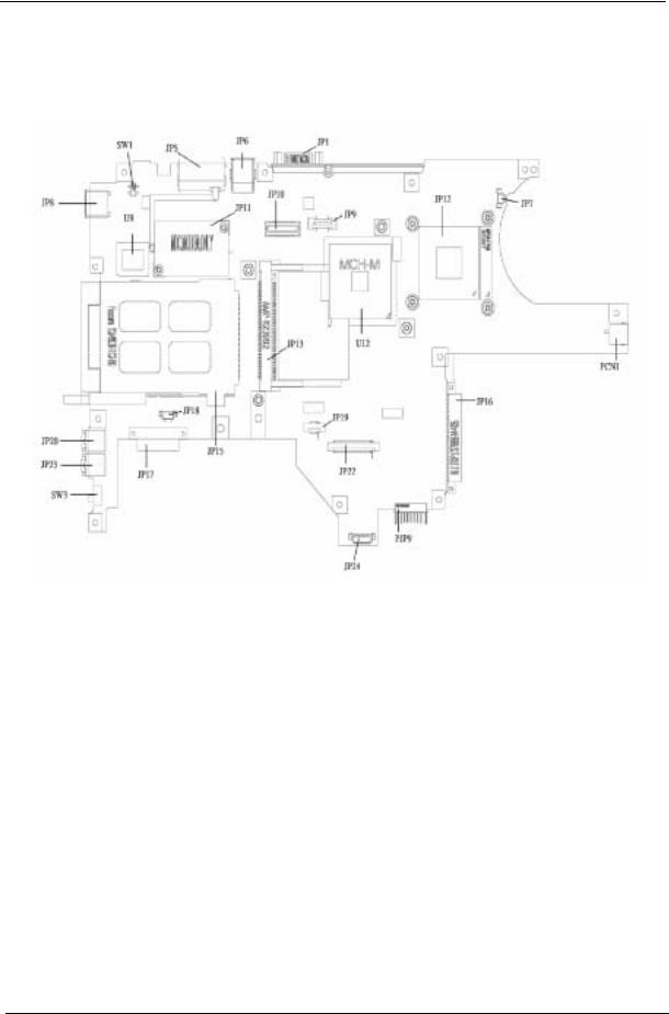
Mainboard Placement
Top View
Item |
Description |
Item |
Description |
|
|
|
|
JP1 |
CRT Connector |
JP18 |
Speaker Connector |
|
|
|
|
JP5 |
RJ11/RJ45 Connector |
JP19 |
Touchpad Board Connector |
|
|
|
|
JP6 |
USB Connector x 2 |
JP20 |
Microphone Jack |
|
|
|
|
JP7 |
CPU Fan Connector |
JP22 |
Keyboard Connector |
|
|
|
|
JP8 |
USB Connector |
JP23 |
Phone Jack |
|
|
|
|
JP9 |
Power Board Connector |
JP24 |
LED Board Connector |
|
|
|
|
JP10 |
LVDS Connector |
U9 |
BIOS ROM |
|
|
|
|
JP11 |
MDC Connector |
U12 |
North Bridge |
|
|
|
|
JP12 |
CPU Socket |
PCN1 |
AC Jack |
|
|
|
|
JP13 |
MiniPCI Connector |
PJP9 |
Battery Connector |
|
|
|
|
JP15 |
CardBus Connector |
SW1 |
LID Switch |
|
|
|
|
JP16 |
HDD Connector |
SW3 |
Kill Switch |
|
|
|
|
JP17 |
ODD Connector |
|
|
|
|
|
|
4 |
Chapter 1 |
Bottom View
Item |
Description |
Item |
Description |
|
|
|
|
U35 |
CardBus Controller |
JP25 |
SO-DIMM Socket |
|
|
|
|
U37 |
EC |
JP26 |
SO-DIMM Socket |
|
|
|
|
U39 |
CODEC |
|
|
|
|
|
|
Chapter 1 |
5 |

Outlook View
A general introduction of ports allow you to connect peripheral devices, as you would with a desktop PC.
Front Open View
# |
Item |
Description |
|
|
|
1 |
Display screen |
Also called Liquid-Crystal Display (LCD), displays |
|
|
computer output. |
|
|
|
2 |
Power button |
Turns on the computer. |
|
|
|
3 |
Launch keys |
Two special keys for frequently used programs. |
|
|
|
4 |
Keyboard |
Inputs data into your computer. |
|
|
|
5 |
Palmrest |
Comfortable support area for your hands when you use the |
|
|
computer. |
|
|
|
6 |
Click buttons |
The left and right buttons function like the left and right |
|
(left and right) |
mouse buttons. |
|
|
|
7 |
Touchpad |
Touch-sensitive pointing device which functions like a |
|
|
computer mouse. |
|
|
|
8 |
Status indicators |
Llight-Emitting Diodes (LEDs) that turn on and off to show |
|
|
the status of the computer, its functions and components. |
|
|
|
6 |
Chapter 1 |

Front View
# |
Item |
Description |
|
|
|
1 |
Optical drive |
Internal optical drive; accepts CDs or DVDs depending on |
|
|
the optical drive type. |
|
|
|
2 |
Optical drive eject |
Ejects the optical drive tray from the drive. |
|
button |
|
|
|
|
3 |
Emergency eject hole |
Ejects the optical drive tray when the computer is turned |
|
|
off. See page 56 for more details. |
|
|
|
4 |
Latch |
Latch for opening and closing the computer. |
|
|
|
5 |
Power indicator |
Lights when the computer is on. |
|
|
|
6 |
Battery indicator |
Lights when the battery is being charged. |
|
|
|
7 |
Wireless / Bluetooth® |
Lights to indicate the status of Wireless LAN (optional) / |
|
communications |
BluetoothR (optional) communications. |
|
|
|
|
|
1. Orange indicates that wireless LAN is |
|
|
enabled. |
|
|
2. Blue indicates that Bluetooth® is enabled. |
|
|
3. Purple indicates that wireless LAN & |
|
|
Bluetooth® are enabled. |
Chapter 1 |
7 |

Left View
# |
Item |
Description |
|
|
|
1 |
One USB 2.0 port |
Connects to Universal Serial Bus devices (e.g., USB |
|
|
mouse, USB camera). |
|
|
|
2 |
PC Card slot |
Accepts one Type II 16-bit PC Card or 32-bit CardBus PC |
|
|
Card. |
|
|
|
3 |
PC Card eject button |
Ejects the PC Card from the slot. |
|
|
|
4 |
Microphone/line-in |
Accepts input from external microphones, or other audio |
|
jack |
line-in devices (e.g. audio CD player, stereo walkman and |
|
|
etc.) |
|
|
|
5 |
Headphone/ Speaker/ |
Connects to headphones or other line-out audio devices |
|
Line-out jack |
(speakers). |
|
|
|
6 |
Wireless / Bluetooth |
Enables and disables Wireless / Bluetooth® |
|
Communication switch |
communication devices. (optional) |
|
|
|
|
|
|
7 |
Stereo speaker |
Generates sound |
|
|
|
8 |
Chapter 1 |

Right View
# |
Item |
Description |
|
|
|
1 |
Stereo speaker |
Outputs sound |
|
|
|
2 |
HDD |
Houses the computer's hard disk |
|
|
|
3 |
DC-in jack |
Connects the AC adapter |
|
|
|
4 |
Ventilation Slot |
Enables the computer to stay cool, even afterprolonged |
|
|
use. |
|
|
|
Chapter 1 |
9 |

Rear View
# |
Item |
Description |
|
|
|
1 |
Security keylock |
Connects to a Kensington-compatible computer security |
|
|
lock |
|
|
|
2 |
External display port |
Connects to a display device (e.g., external monitor, LCD |
|
|
projector) and displays up to16.7 million colors and up to |
|
|
1600x1200 at 85 Hz and 2048x1536 at 75 Hz resolution. |
|
|
|
3 |
Two USB 2.0 ports |
Connects to Universal Serial Bus devices (e.g.,USB |
|
|
mouse, USB camera) |
|
|
|
4 |
Modem port |
Connects to a phone line |
|
|
|
5 |
Ethernet port |
Connects to an Ethernet 10/100-based network |
|
|
|
10 |
Chapter 1 |
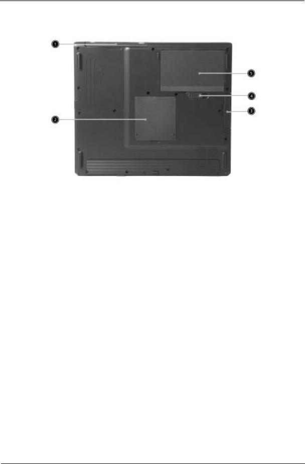
Bottom View
# |
Item |
Description |
|
|
|
1 |
Optical drive |
Internal optical drive; accepts CDs or DVDs depending on |
|
|
the optical drive type |
|
|
|
2 |
Memory compartment |
Houses the computer's main memory |
|
|
|
3 |
Hard disk bay |
Houses the computer's hard disk (secured by a screw) |
|
|
|
4 |
Battery compartment |
Unlatches the battery to remove the battery compartment |
|
release latch |
|
|
|
|
5 |
Battery bay |
Houses the computer's battery pack |
|
|
|
Chapter 1 |
11 |

Indicators
The computer has six easy-to-read status icons below the display screen.
The status LCD displays icons that show the status of the computer and its components.
Icon |
Function |
Description |
|
HDD |
Lights when Hard Disk Drive is activated. |
|
ODD |
Lights when Optical Disk Drive is activated. |
|
Scroll lock |
Lights when Scroll Lock is activated. |
|
Caps lock |
Lights when Caps Lock is activated. |
|
Pad lock (cursor) |
Lights when Pad lock is activated. |
|
Num lock |
Lights when Num Lock is activated. |
|
Power Indicator |
Lights when the computer is on |
|
Battery |
Lights green. Flashes when the battery is |
|
|
being charged or low capacity. |
|
Wireless |
Lights to indicate the status of Wireless |
|
Communications |
LAN(optional) communications |
12 |
Chapter 1 |

Lock Keys
The keyboard has four lock keys which you can toggle on and off.
Lock Key |
Description |
|
|
Caps Lock |
When Caps Lock is on, all alphabetic characters typed |
|
are in uppercase. |
|
|
Pad lock |
When Pad Lock is on, the embedded keypad is |
(Fn-F10) |
enabled. In this mode the keypad is cursor function. |
|
|
Num lock |
When Num Lock is on, the embedded keypad is in |
(Fn-F11) |
numeric mode. The keys function as a calculator |
|
(complete with the arithmetic operators +, -, *, and /). |
|
Use this mode when you need to do a lot of numeric |
|
data entry. A better solution would be to connect an |
|
external keypad. |
|
|
Scroll lock |
When Scroll Lock is on, the screen moves one line up |
(Fn-F12) |
or down when you press w and y respectively. |
|
Scroll Lock does not work with some applications. |
|
|
Chapter 1 |
13 |

Embedded Numeric Keypad
The embedded numeric keypad functions like a desktop numeric keypad. It is indicated by small characters located on the right hand side of the keycaps.
Desired Access |
Num Lock On |
Num Lock Off |
|
|
|
Number keys on embedded |
Type numbers in a normal |
|
keypad |
manner. |
|
|
|
|
Main keyboard keys |
Hold <Fn> while typing |
Type the letters in a normal |
|
letters on embedded |
manner. |
|
keypad. |
|
|
|
|
14 |
Chapter 1 |
Windows Keys
The keyboard has two keys that perform Windows-specific functions.
Key |
Description |
|
|
Windows logo key |
Start button. Combinations with this key perform special |
|
functions. Below are a few examples: |
|
+ Tab (Activates next taskbar button) |
 + E (Explores My Computer)
 + F (Finds Document)
+ M (Minimizes All)
j +  + M (Undoes Minimize All)
+ R (Displays the Run... dialog box)
Application key Opens a context menu (same as a right-click).
Chapter 1 |
15 |

Hot Keys
The computer uses hotkey or key combinations to access most of the computer’s controls like sreen brightness and volume output.
To activate hot keys, press and hold the Fn key before pressing the other key in the hot key combination.
Hot Key |
Icon |
Function |
Description |
|
|
|
|
Fn-Esc |
|
Sleep |
Puts the computer in Sleep mode. |
|
|
|
|
Fn-F5 |
|
Display toggle |
Switches display output between the display screen, |
|
|
|
external monitor (if connected) and both the display |
|
|
|
screen and external monitor. |
|
|
|
|
Fn-End |
|
Speaker toggle |
Turns the speakers on and off. |
|
|
|
|
Fn-PgUp |
|
Volume up |
Increases the speaker volume. |
|
|
|
|
Fn-PgDn |
|
Volume down |
Decreases the speaker volume. |
|
|
|
|
Fn-w |
|
Brightness up |
Increases the screen brightness. |
|
|
|
|
Fn-y |
|
Brightness down |
Decreases the screen brightness |
|
|
|
|
16 |
Chapter 1 |

The Euro Symbol
If your keyboard layout is set to United States-International or United Kingdom or if you have a keyboard with a European layout, you can type the Euro symbol on your keyboard.
NOTE: For US keyboard users: The keyboard layout is set when you first set up Windows. For the Euro symbol to work, the keyboard layout has to be set to United States-International.
To verify the keyboard type in Windows 2000 and Windows Millennium Edition, follow the steps below:
1.Click on Start, Settings, Control Panel.
2.Double-click on Keyboard.
3.Click on the Language tab.
4.Verify that keyboard layout used for “En English (United States)” is set to United States-International. If not, select and click on Properties; then select United States-International and click on OK.
5.Click on OK.
To verify the keyboard type in Windows XP, follow the steps below:
1.Click on Start, Control Panel.
2.Double-click on Regional and Language Options.
3.Click on the Language tab and click on Details.
4.Verify that the keyboard layout used for "En English (United States)" is set to United States-International. If not, select and click on ADD; then select United States-International and click on OK.
5.Click on OK.
To type the Euro symbol:
1.Locate the Euro symbol on your keyboard.
2.Open a text editor or word processor.
3.Hold Alt Gr and press the Euro symbol.
NOTE: Some fonts and software do not support the Euro symbol. Please refer to www.microsoft.com/ typography/faq/faq12.htm for more information.
Chapter 1 |
17 |

Launch Keys
Located at the top of keyboard are three buttons. The left-most button is the power button. To the right of the power button are the two launch keys. They are designated as the programmable buttons (P1 and P2).
Launch Key |
Default application |
|
|
e |
Acer eManager application (User-programmable) |
|
|
P |
User-programmable |
|
|
18 |
Chapter 1 |

Touchpad
The built-in touchpad is a pointing device that senses movement on its surface. This means the cursor responds as you move your finger on the surface of the touchpad. The central location on the palmrest provides optimum comfort and support.
Touchpad Basics
The following items teach you how to use the touchpad:
!Move your finger across the touchpad to move the cursor.
!Press the left and right buttons located on the edge of the touchpad to do selection and execution functions. These two buttons are similar to the left and right buttons on a mouse. Tapping on the touchpad produces similar results.
Function |
Left Button |
Right Button |
Tap |
|
|
|
|
Execute |
Click twice |
|
Tap twice (at the same |
|
quickly |
|
speed as double-clicking |
|
|
|
the mouse button) |
|
|
|
|
Select |
Click once |
|
Tap once |
|
|
|
|
Drag |
Click and hold, |
|
Tap twice (at the same |
|
then use finger |
|
speed as double-clicking |
|
to drag the |
|
a mouse button) then hold |
|
cursor on the |
|
finger to the touchpad on |
|
touchpad |
|
the second tap to drag the |
|
|
|
cursor |
|
|
|
|
Access context |
|
Click once |
|
menu |
|
|
|
|
|
|
|
NOTE: Keep your fingers dry and clean when using the touchpad. Also keep the touchpad dry and clean. The touchpad is sensitive to finger movements. Hence, the lighter the touch, the better the response. Tapping harder will not increase the touchpad’s responsiveness.
Chapter 1 |
19 |

Hardware Specifications and Configurations
Processor
Item |
Specification |
|
|
CPU type |
Intel® Celeron® M Processor at 1.5 GHz (or higher) |
CPU package |
µ FCBGA package |
|
|
CPU core voltage |
Intel® Celeron® M Processor supports automatic selection of power supply |
|
voltage |
|
|
CPU I/O voltage |
1.05V |
|
|
BIOS |
|
|
|
Item |
Specification |
|
|
BIOS vendor |
Insyde |
|
|
BIOS Version |
Insyde MobilePRO BIOS 4.0 |
|
|
BIOS ROM type |
Flash ROM |
|
|
BIOS ROM size |
512KB |
|
|
BIOS package |
32 lead of PLCC |
|
|
Bupported protocols |
ACPI 1.0b,PC Card 95, SM BIOS 2.3, EPP/IEEE 1284, ECP/IEEE 1284 |
|
1.7 & 1.9, PCI 2.2, PnP 1.0a, DMI 2.0, USB, VGA BIOS, CD-ROM bootable |
|
|
BIOS password control |
Set by setup manual |
|
|
Second Level Cache |
|
|
|
Item |
Specification |
|
|
Cache controller |
Built-in CPU |
|
|
Cache size |
Intel® Celeron® M Processor 512K |
1st level cache control |
Always enabled |
|
|
2nd level cache control |
Always enabled |
|
|
Cache scheme control |
Fixed in write-through |
|
|
System Memory |
|
|
|
Item |
Specification |
|
|
Memory controller |
Intel® 852GM |
Memory size |
128MB/256MB/512MB/1024MB(1GB) |
|
|
DIMM slot number |
2 slots |
|
|
Supports memory size per socket |
1GB |
|
|
Supports maximum memory size |
2GB (by two 1024MB SO-DIMM module) |
|
|
Supports DIMM type |
DDR Synchronous DRAM |
|
|
Supports DIMM Speed |
266 MHz |
|
|
Supports DIMM voltage |
2.5V |
|
|
Supports DIMM package |
200-pin SO-DIMM |
|
|
Memory module combinations |
You can install memory modules in any combinations as long as they |
|
match the above specifications. |
|
|
20 |
Chapter 1 |

Memory Combinations
Slot 1 |
Slot 2 |
Total Memory |
|
|
|
0MB |
128MB |
128MB |
|
|
|
0MB |
256MB |
256MB |
|
|
|
0MB |
512MB |
512MB |
|
|
|
0MB |
1024MB |
1024MB |
|
|
|
128MB |
0MB |
128MB |
|
|
|
128MB |
128MB |
256MB |
|
|
|
128MB |
256MB |
384MB |
|
|
|
128MB |
512MB |
640MB |
|
|
|
128MB |
1024MB |
1152MB |
|
|
|
256MB |
0MB |
256MB |
|
|
|
256MB |
128MB |
384MB |
|
|
|
256MB |
256MB |
512MB |
|
|
|
256MB |
512MB |
768MB |
|
|
|
256MB |
1024MB |
1280MB |
|
|
|
512MB |
0MB |
512MB |
|
|
|
512MB |
128MB |
640MB |
|
|
|
512MB |
256MB |
768MB |
|
|
|
512MB |
512MB |
1024MB |
|
|
|
512MB |
1024MB |
1536MB |
|
|
|
1024MB |
0MB |
1024MB |
|
|
|
1024MB |
128MB |
1152MB |
|
|
|
1024MB |
256MB |
1280MB |
|
|
|
1024MB |
512MB |
1536MB |
|
|
|
1024MB |
1024MB |
2048MB(2G) |
|
|
|
NOTE: Above table lists some system memory configurations. You may combine DIMMs with various capacities to form other combinations.
.
LAN Interface
Item |
Specification |
|
|
Supports LAN protocol |
10/100 Mbps |
|
|
LAN connector type |
RJ45 |
|
|
LAN connector location |
Rear Side |
|
|
.
Modem/Bluethooth Interface
Item |
Specification |
|
|
Data modem data baud rate (bps) |
56K |
|
|
Supports modem/bluetooth protocol |
V.92 WWDAA |
|
|
Modem connector type |
RJ11 |
|
|
Modem connector location |
Rear Side |
|
|
Chapter 1 |
21 |
Loading...