

Page 1
ARMC/3P
User Guide
Release 04.02.00
Copyright © 2007 Acer Inc
Userguide_ARMC/3P_v2
March 2007
100-80-8250-00
Page 2

Page 3

Copyright and Trademark Information
LISTED
1F6 1
This document contains proprietary information that is protected by copyright. All rights
reserved. No part of this document may be photocopied, reproduced, or translated into
another language without express prior written consent of Acer Inc.
© Copyright 2007 Acer Inc, All rights reserved. Java is a registered trademark of Sun
Microsystems, Inc. Internet Explorer is a registered trademark of Microsoft Corporation.
Netscape and Netscape Navigator are registered trademarks of Netscape
Communication Corporation. The Raritan logo are trademarks of Raritan Computer, Inc.
All other marks are the property of their respective owners.
FCC Information
This equipment has been tested and found to comply with the limits for a Class A digital
device, pursuant to Part 15 of the FCC Rules. These limits are designed to provide
reasonable protection against harmful interference in a commercial installation. This
equipment generates, uses, and can radiate radio frequency energy and if not installed
and used in accordance with the instructions, may cause harmful interference to radio
communications. Operation of this equipment in a residential environment may cause
harmful interference.
Japanese Approvals
Acer is not responsible for damage to this product resulting from accident, disaster,
misuse, abuse, non-Acer modification of the product, or other events outside of Acer’s
reasonable control or not arising under normal operating conditions.
U
US
C
L
I.T.E .
For assistance around the world, please see the back cover of this guide for
regional Acer Inc contact information.
Page 4

Safety Guidelines
To avoid potentially fatal shock hazard and possible damage to Acer equipment:
• Test AC outlets at your computer and monitor for proper polarity and grounding.
• Use only with grounded outlets at both the computer and monitor. When using a
backup UPS, power the computer, monitor and appliance off the supply.
Page 5

C
ONTENTS
i
Contents
ARMC/3P
ARMC/3P ................................
ARMC/3PARMC/3P
Contents
Contents ................................
ContentsContents
Figures
Figures................................
FiguresFigures
Tables
Tables................................
TablesTables
Chapter 1: Introduction
Chapter 1: Introduction ................................
Chapter 1: IntroductionChapter 1: Introduction
Product Overview ......................................................................................................1
Product Photos..........................................................................................................1
Product Features.......................................................................................................3
Terminology............................................................................................................... 3
Package Contents .....................................................................................................5
When the Server is up and running ........................................................................... 5
When the Server is dead ...........................................................................................6
................................................................
................................................................
................................................................
................................................................
................................................................
................................................................
................................................................
................................................................
................................................................
................................................................
........................................................
................................................................
.........................................................
................................................................
...........................................................
................................................................
............................................................
................................................................
.................................... 1111
................................................................
........................ 1111
................................................
......................... iiii
..................................................
...........................iv
......................................................
............................vi
........................................................
iv
iviv
vi
vivi
Chapter 2: Installation
Chapter 2: Installation ................................
Chapter 2: InstallationChapter 2: Installation
Operation Overview................................................................................................... 7
Connectors and Jumpers........................................................................................... 7
Serial Interface...................................................................................................................................8
USB Plug ...........................................................................................................................................8
Video/USB System Interface .............................................................................................................8
10/100 Mpbs Ethernet Adaptor..........................................................................................................8
External Power Option.......................................................................................................................8
Power using ATX Power Cable Adaptor ............................................................................................8
ATX Power Reset ..............................................................................................................................8
Intelligent Management Platform Bus Connector (IPMB) ..................................................................9
The Set to Default (S2D) Pins ...........................................................................................................9
Serial 1, Serial 2 and PS/2.................................................................................................................9
Placing the ARMC/3P into the Server...................................................................... 11
Open the Server ..............................................................................................................................11
Plugging an ARMC/3P into a PCI Slot .............................................................................................11
Chapter 3: Configuration
Chapter 3: Configuration ................................
Chapter 3: ConfigurationChapter 3: Configuration
Initial Configuration.................................................................................................. 17
ARMC/3P Psetup Tool ............................................................................................ 17
Using the Psetup Tool via Graphical User Interface ........................................................................17
Running the Linux Psetup Tool via Command Line .........................................................................18
Mac Address Detection ........................................................................................... 20
Authentication.......................................................................................................... 20
Initial Configuration via DHCP Server...................................................................... 21
Initial Configuration via Serial Console ....................................................................21
Web Interface..........................................................................................................22
Mouse, Keyboard and Video configuration ..............................................................22
ARMC/3P USB interface..................................................................................................................22
ARMC/3P Keyboard Settings ..........................................................................................................23
Remote Mouse Settings ..................................................................................................................23
Auto Mouse Speed and Mouse Synchronization .............................................................................23
Host System Mouse Settings...........................................................................................................24
Single and Double Mouse Mode......................................................................................................25
Recommended Mouse Settings.......................................................................................................25
Video Modes....................................................................................................................................26
Resetting the ARMC/3P to its Factory Settings........................................................ 26
Using the S2D Pins..........................................................................................................................26
Using the Serial Interface ................................................................................................................26
................................................................
................................................................
.............................................................
................................................................
..................................
................................................................
............................. 17
..........................................................
.. 7777
....
17
1717
Page 6

ii C
Chapter 4: Usage
Chapter 4: Usage................................
Chapter 4: UsageChapter 4: Usage
................................................................
................................................................
.........................................
................................................................
......... 27
..................
Prerequisites ........................................................................................................... 27
HTTP/HTTPS ..................................................................................................................................27
Telnet...............................................................................................................................................27
SSH .................................................................................................................................................27
Login into the ARMC/3P and logout.........................................................................28
Login into the ARMC/3P ..................................................................................................................28
Navigation........................................................................................................................................29
Logout from the ARMC/3P...............................................................................................................31
Managing the ARMC/3P with a CommandCenter....................................................31
The Remote Console...............................................................................................31
General Description .........................................................................................................................31
Main Window ...................................................................................................................................32
Remote Console Control Bar...........................................................................................................33
Remote Console Options.................................................................................................................34
Remote Console Status Line ...........................................................................................................44
Optimizing the Video Picture ...........................................................................................................45
Reducing the Noise of the Video Picture .........................................................................................46
Using the ARMC/3P with low bandwidth..........................................................................................47
Chapter 5: Menu Options
Chapter 5: Menu Options................................
Chapter 5: Menu OptionsChapter 5: Menu Options
.............................................................
................................................................
............................. 49
..........................................................
Remote Control ....................................................................................................... 49
KVM Console...................................................................................................................................49
Remote Power.................................................................................................................................49
Telnet Console.................................................................................................................................51
Virtual Media ........................................................................................................... 54
Floppy Disk......................................................................................................................................54
CD ROM ..........................................................................................................................................55
Drive Redirection .............................................................................................................................59
Options ............................................................................................................................................62
Creating an Image ...........................................................................................................................63
System Health.........................................................................................................65
Chassis Control ...............................................................................................................................65
Monitor Sensors...............................................................................................................................65
System Event Log............................................................................................................................66
Alarm Settings .................................................................................................................................66
User Management................................................................................................... 67
Change Password ...........................................................................................................................67
User and Groups .............................................................................................................................67
Permissions .....................................................................................................................................69
KVM Settings........................................................................................................... 70
User Console...................................................................................................................................70
Power Control..................................................................................................................................73
Keyboard/Mouse..............................................................................................................................74
Video ...............................................................................................................................................75
Device Settings .......................................................................................................78
Network ...........................................................................................................................................78
Dynamic DNS ..................................................................................................................................81
Security............................................................................................................................................83
Certificate ........................................................................................................................................86
Serial Port........................................................................................................................................89
Intelligent Platform Management Interface (IPMI)............................................................................92
Date/Time ........................................................................................................................................93
Authentication..................................................................................................................................93
Event Log ........................................................................................................................................96
SNMP Settings ................................................................................................................................98
Maintenance.......................................................................................................... 101
Device Information.........................................................................................................................101
Language.......................................................................................................................................102
Event Log ......................................................................................................................................103
Update Firmware ...........................................................................................................................103
Unit Reset......................................................................................................................................104
ONTENTS
27
2727
49
4949
Appendix A: Specifications
Appendix A: Specifications ................................
Appendix A: SpecificationsAppendix A: Specifications
........................................................
................................................................
........................105
................................................
Sizes and Weights................................................................................................. 105
Environment .......................................................................................................... 105
Temperature ..................................................................................................................................105
105
105105
Page 7

C
ONTENTS
iii
Humidity.........................................................................................................................................105
Appendix B: ARMC/3P Video Modes
Appendix B: ARMC/3P Video Modes ................................
Appendix B: ARMC/3P Video ModesAppendix B: ARMC/3P Video Modes
Appendix C: Key Codes
Appendix C: Key Codes ................................
Appendix C: Key CodesAppendix C: Key Codes
Appendix D: Pin Assignment
Appendix D: Pin Assignment ................................
Appendix D: Pin AssignmentAppendix D: Pin Assignment
VGA HD-15 ........................................................................................................... 111
RJ45 Connetcor Ethernet ...................................................................................... 111
IPMB/I2 Connector ................................................................................................ 111
Serial SUB-D9 Connector 1...................................................................................112
PS/2 Connector..................................................................................................... 112
USB....................................................................................................................... 112
Appendix E: Troub
Appendix E: Troubleshooting
Appendix E: TroubAppendix E: Troub
Appendix F: GNU General Public License (GPL)
Appendix F: GNU General Public License (GPL) ........................
Appendix F: GNU General Public License (GPL)Appendix F: GNU General Public License (GPL)
Appendix G: The OpenLADAP Public License
Appendix G: The OpenLADAP Public License ............................
Appendix G: The OpenLADAP Public LicenseAppendix G: The OpenLADAP Public License
leshooting ................................
leshootingleshooting
..............................................................
................................................................
......................................................
................................................................
.....................................................
................................................................
...........................................
................................................................
..............................109
............................................................
......................111
............................................
.....................113
..........................................
........................115
................................................
............................121
........................................................
...........107
......................
107
107107
109
109109
111
111111
113
113113
115
115115
121
121121
Page 8

iv F
Figures
IGURES
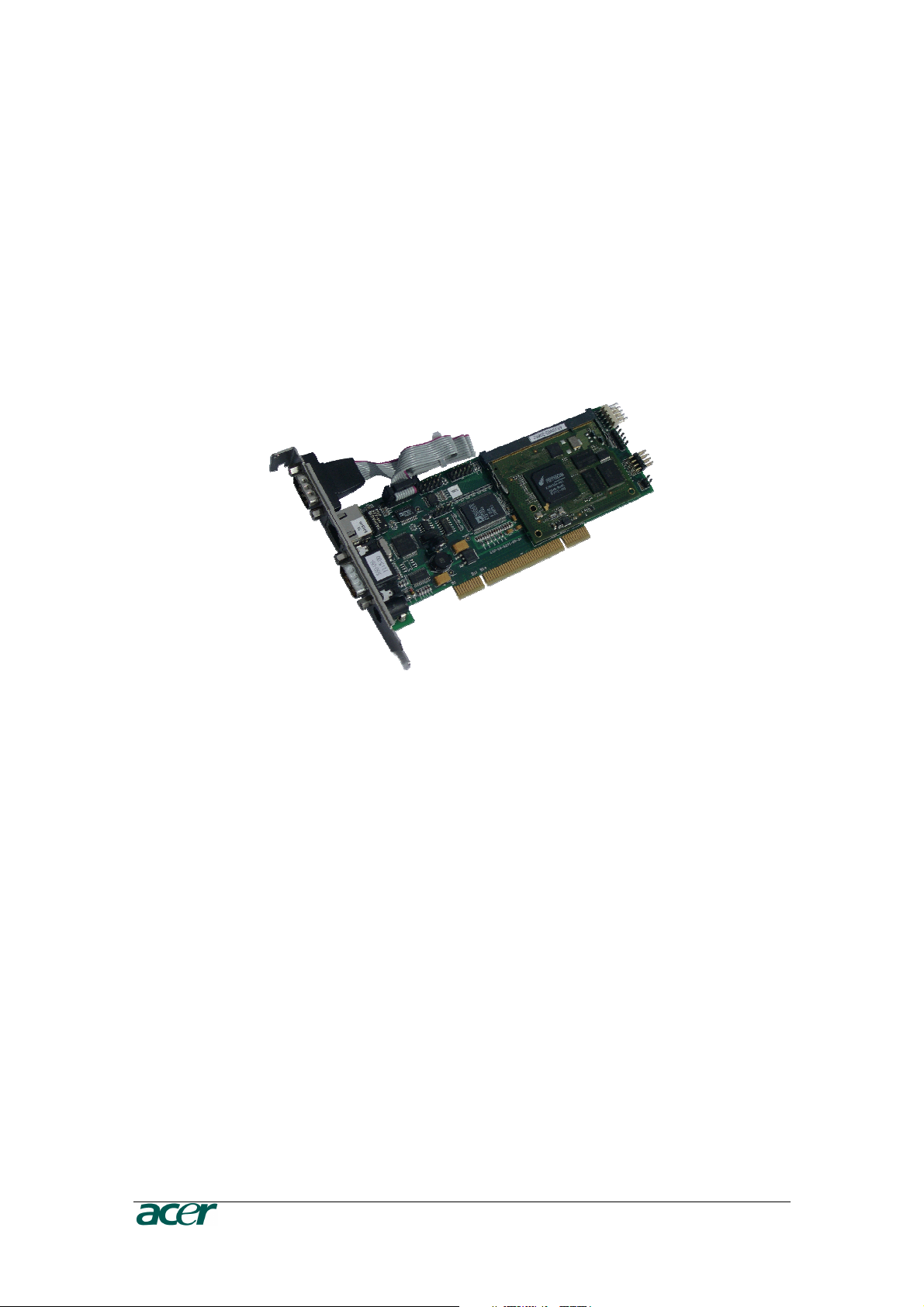
Figure 1 ARMC/3P with High-Profil Bracket................................................................................................. 1
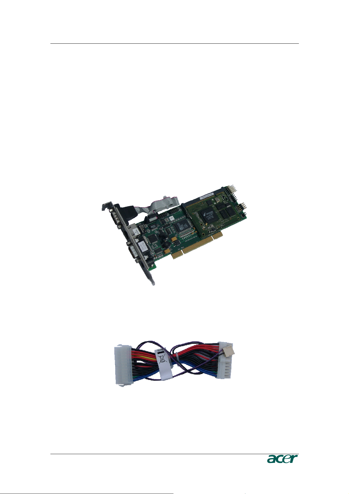
Figure 2 24-pole ATX Power Cable Adaptor ................................................................................................ 1
Figure 3 ARMC/3P with Low-Profil Bracket.................................................................................................. 2
Figure 4 IPMB Cable, Power Cable, Reset Cable........................................................................................ 2
Figure 5 Serial Cable ................................................................................................................................... 2
Figure 6 VGA-USB System Cable and PS/2 System Cable......................................................................... 2
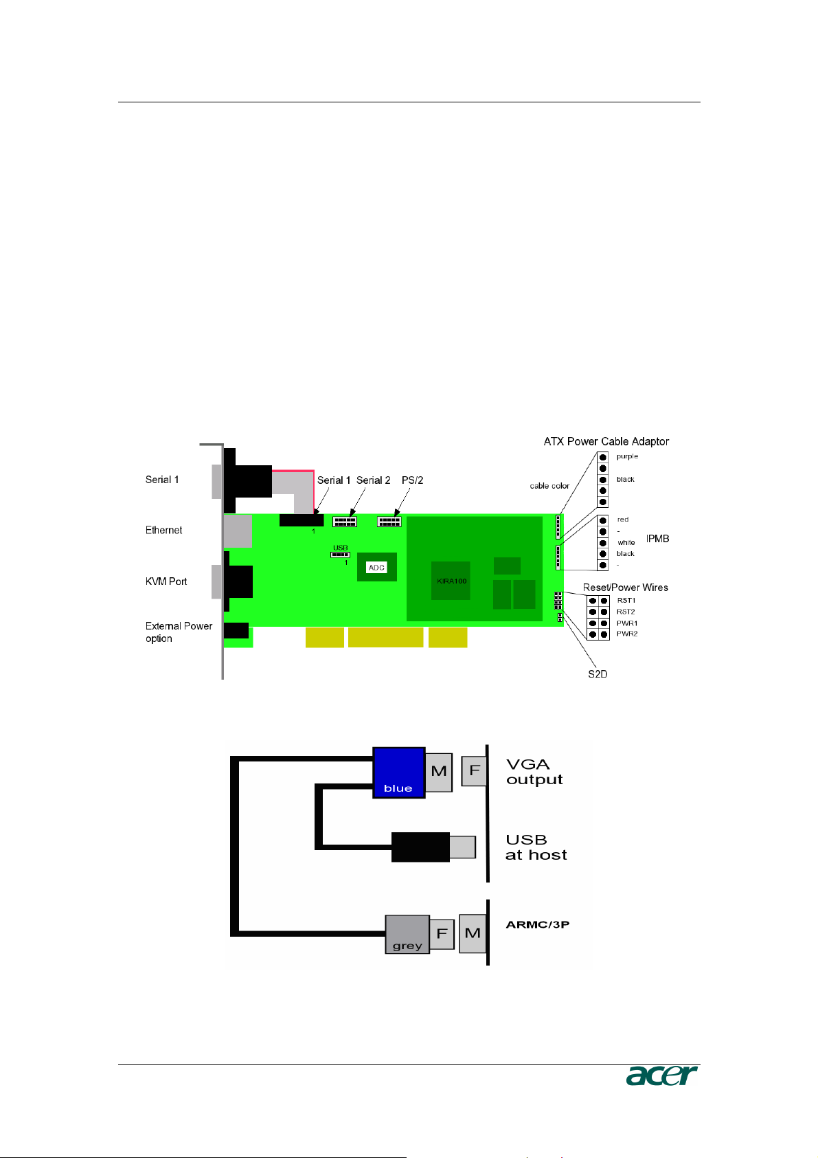
Figure 7 ARMC/3P Internal Connectors....................................................................................................... 7
Figure 8 Connection of the ARMC/3P VGA-USB System Cable.................................................................. 7
Figure 9 ARMC/3P Reset/Power Connection Pinout ................................................................................... 9
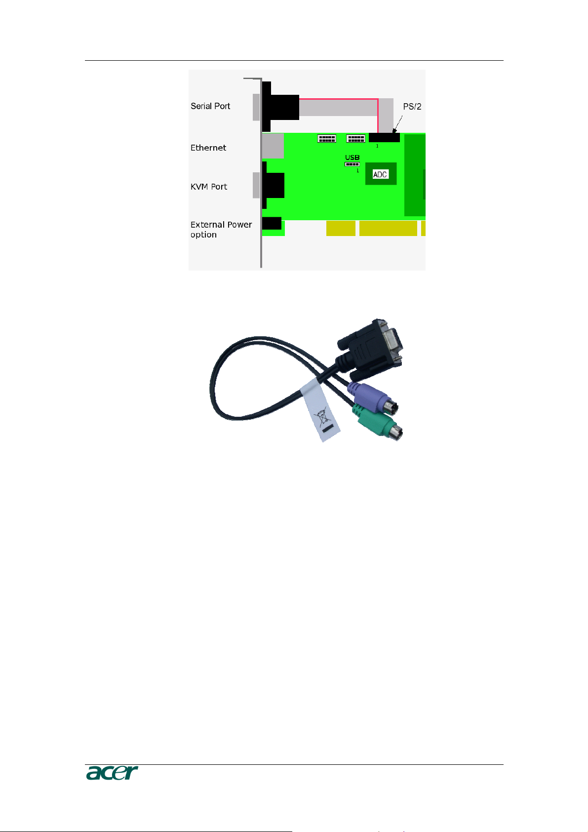
Figure 10 ARMC/3P with PS/2................................................................................................................... 10
Figure 11 PS/2 System Cable.................................................................................................................... 10
Figure 12 Mounting the ARMC/3P into a PCI Slot ..................................................................................... 11
Figure 13 IPMB Cable................................................................................................................................ 11
Figure 14 IPMB Connector......................................................................................................................... 12
Figure 15 Power using Reset/Power Wires................................................................................................ 12
Figure 16 Power using ATX Power Cable Adaptor .................................................................................... 14
Figure 17 ARMC/3P Psetup Tool (Windows Version)................................................................................ 18
Figure 18 ARMC/3P Psetup Tool (Linux Version)...................................................................................... 18
Figure 19 Remote Console Control Bar: Sync Button................................................................................ 24
Figure 20 Terminal with Reset Message.................................................................................................... 26
Figure 21 The Internet Explorer displaying the Encryption Key Length ..................................................... 28
Figure 22 Login Screen.............................................................................................................................. 28
Figure 23 Password Change Request ....................................................................................................... 29
Figure 24 ARMC/3P Main Page Overview ................................................................................................. 30
Figure 25 Navigation Frame Overview....................................................................................................... 30
Figure 26 Logout Link ................................................................................................................................ 31
Figure 27 Remote Console ........................................................................................................................ 32
Figure 28 Remote Console Control Bar ..................................................................................................... 33
Figure 29 Remote Console Options Menu ................................................................................................. 34
Figure 30 Remote Console Options Menu: Scaling ................................................................................... 35
Figure 31 Remote Console Options Menu: Mouse Handling ..................................................................... 36
Figure 32 Remote Console Options Menu: Local Cursor........................................................................... 37
Figure 33 Remote Console Options Menu: Chat Window.......................................................................... 37
Figure 34 Remote Console Options Menu: Video Settings Panel.............................................................. 39
Figure 35 Remote Console Options Menu: Softkeyboard.......................................................................... 41
Figure 36 Soft Keyboard Mapping ............................................................................................................. 41
Figure 37 Remote Console Options Menu: Hotkey Confirmations Dialog.................................................. 42
Figure 38 Remote Console Options Menu: Encoding - Predefined............................................................ 42
Figure 39 Remote Console Options Menu: Encoding - Compression........................................................ 43
Figure 40 Remote Console Options Menu: Encoding – Color Depth ......................................................... 44
Figure 41 Remote Console Status Line ..................................................................................................... 44
Figure 42 Status Line Transfer Rate .......................................................................................................... 45
Figure 43 Remote Console Video Settings: Reset this Mode .................................................................... 46
Figure 44 Main Page with Remote Console Preview ................................................................................. 49
Figure 45 Power Control Overview ............................................................................................................ 50
Figure 46 ‘Internal Power Control’ Buttons................................................................................................. 50
Figure 47 ‘Power Control via IPMI’ Buttons................................................................................................ 51
Figure 48 Telnet Console........................................................................................................................... 52
Figure 49 Floppy Virtual Area .................................................................................................................... 54
Figure 50 Select Image File ....................................................................................................................... 55
Figure 51 Active Image File ....................................................................................................................... 55
Page 9

F
IGURES
v
Figure 52 Selecting CD-ROM and Windows Share ................................................................................... 56
Figure 53 The Image File on the Share...................................................................................................... 57
Figure 54 Explorer Context Menu .............................................................................................................. 58
Figure 55 Share Configuration Dialog........................................................................................................ 58
Figure 56 Drive Redirection ....................................................................................................................... 59
Figure 57 Main View .................................................................................................................................. 60
Figure 58 Selecting the desired Drive ........................................................................................................ 61
Figure 59 Selection Write Support ............................................................................................................. 61
Figure 60 Device Authentification .............................................................................................................. 61
Figure 61 Virtual Drive Selection................................................................................................................ 62
Figure 62 Tray Info..................................................................................................................................... 62
Figure 63 USB Mass Storage Option......................................................................................................... 62
Figure 64 RawWrite for Windows Selection Dialog.................................................................................... 63
Figure 65 Nero Selection Dialog ................................................................................................................ 64
Figure 66 Chassis Control.......................................................................................................................... 65
Figure 67 Monitor Sensors Overview......................................................................................................... 66
Figure 68 System Event Log Overview...................................................................................................... 66
Figure 69 IPMI Alarm Configuration........................................................................................................... 66
Figure 70 Set Password............................................................................................................................. 67
Figure 71 User/Group Management .......................................................................................................... 67
Figure 72 User/Group Permission Settings................................................................................................ 69
Figure 73 User Console Settings (Part 1) .................................................................................................. 70
Figure 74 User Console Settings (Part 2) .................................................................................................. 71
Figure 75 Power Control ............................................................................................................................ 73
Figure 76 Keyboard and Mouse Settings................................................................................................... 74
Figure 77 Video Settings............................................................................................................................ 77
Figure 78 Network Settings........................................................................................................................ 78
Figure 79 Dynamic DNS ............................................................................................................................ 81
Figure 80 Dynamic DNS Scenario ............................................................................................................. 81
Figure 81 Security Settings ........................................................................................................................ 83
Figure 82 Certificate Settings..................................................................................................................... 87
Figure 83 SSL Certificate Upload............................................................................................................... 88
Figure 84 Serial Settings............................................................................................................................ 90
Figure 85 IPMI Settings.............................................................................................................................. 92
Figure 86 Date and Time ........................................................................................................................... 93
Figure 87 Authentication Settings .............................................................................................................. 95
Figure 88 Event Log Settings..................................................................................................................... 97
Figure 89 SNMP Settings........................................................................................................................... 99
Figure 90 Device Information ................................................................................................................... 101
Figure 91 Connected Users ..................................................................................................................... 101
Figure 92 Voltages Overview ................................................................................................................... 102
Figure 93 Language Settings ................................................................................................................... 102
Figure 94 Event Log List .......................................................................................................................... 103
Figure 95 Update Firmware Dialog .......................................................................................................... 103
Figure 96 Unit Reset ................................................................................................................................ 105
Figure 97 English (US) keyboard Layout, used for the key codes ........................................................... 109
Figure 98 VGA HD-15.............................................................................................................................. 111
Figure 99 RJ45 ........................................................................................................................................ 111
Figure 100 Serial Connector .................................................................................................................... 112
Page 10

vi F
Tables
IGURES
Table 1 Hardware Failures........................................................................................................................... 6
Table 2 Host System Failures and how they are detected........................................................................... 6
Table 3 Voltage and Power Specification................................................................................................... 14
Table 4 Initial Network Configuration ......................................................................................................... 17
Table 5 Serial Line Parameters.................................................................................................................. 21
Table 6 Standard User Settings ................................................................................................................. 22
Table 7 Standard User Settings ................................................................................................................. 29
Table 9 Links for Navigation....................................................................................................................... 30
Table 10 Buttons displaying the Access Status ......................................................................................... 45
Table 11 Buttons displaying the Monitor State........................................................................................... 45
Table 12 ARMC/3P Specifications ........................................................................................................... 105
Table 13 Temperature ............................................................................................................................. 105
Table 14 Humidity .................................................................................................................................... 105
Table 15 ARMC/3P Video Modes ............................................................................................................ 107
Table 16 Key Names ............................................................................................................................... 109
Table 17 VGA HD-15 ............................................................................................................................... 111
Table 18 RJ45.......................................................................................................................................... 111
Table 19 IPMB/I2C Connector ................................................................................................................. 111
Table 20 Serial Connector 1 .................................................................................................................... 112
Table 21 Serial Connetcor 2 .................................................................................................................... 112
Table 22 PS/2 Connector......................................................................................................................... 112
Table 23 USB Connector ......................................................................................................................... 112
Page 11

F
IGURES
vii
Page 12

Page 13
C
HAPTER 1: INTRODUCTION
1
Chapter 1: Introduction
Product Overview
The ARMC/3P is a manufacturer-independent remote administration system. The
ARMC/3P works as an integrated solution on your server system. Based on an
embedded operating system, the ARMC/3P provides both exceptional stability and
permanent availability independent of the present state of the server’s operating system.
As a system administrator, you have entire control and location-independent remote
access to react upon both critical incidents and cases of necessary maintenance.
Product Photos
Figure 1 ARMC/3P with High-Profil Bracket
Figure 2 24-pole ATX Power Cable Adaptor
Page 14

2 P
Figure 3 ARMC/3P with Low-Profil Bracket
RODUCT USER GUIDE
Figure 4 IPMB Cable, Power Cable, Reset Cable
Figure 5 Serial Cable
Figure 6 VGA-USB System Cable and PS/2 System Cable
Page 15

C
HAPTER 1: INTRODUCTION
3
Product Features
The ARMC/3P defines a new class of remote access devices. It combines digital remote
access via IP networks with comprehensive and integrated system management. The
ARMC/3P offers convenient, remote KVM access and control via LAN or Internet. It
captures, digitizes, and compresses video and transmits it with keyboard and mouse
signals to and from a remote computer. Remote access and control software runs on its
embedded processors only, but not on mission critical servers, so there is no
interference with server operation or impact on network performance.
Furthermore, the ARMC/3P offers additional remote power management with the help of
optional available devices. Features of the ARMC/3P are:
- KVM (keyboard, video, mouse) access over IP or telephone line
- No impact on server or network performance
- Automatically senses video resolution for best possible screen capture
- High-performance mouse tracking and synchronization
- Port to connect a user console for direct analogous access to KVM device
- Local mouse suppression (only when using SUN’s Java Virtual Machine)
- Remote Power Management
- Remote Virtual Media
Terminology
ACPI
Advanced Configuration and Power Interface
A specification that enables the operating system to implement power
management and system configuration.
ATX
Advanced Technology Extended
A specification that covers the style of motherboards and enclosures
introduced by Intel in 1995.
Client
The workstation of the user for connecting the host system through the
ARMC/3P.
DHCP
Dynamic Host Configuration Protocol
A protocol for dynamically assigning IP addresses to host names,
especially used in a local network.
DNS
Domain Name System
A protocol used to locate computers on the Internet by their name.
FAQ
Frequently Asked Questions
Page 16

4 P
Host
Host System
The server system which is hosting the ARMC/3P.
HTTP
Hypertext Transfer Protocol
One of the protocols used for communication between single computers,
especially between web browsers and web servers.
HTTPS
Hypertext Transfer Protocol Secure
The secure version of HTTP.
IPMI
Intelligent Platform Management Interface
A specification defining a set of common interfaces for operating system
independent platform management and health monitoring.
LED
Light Emitting Diode
A semiconductor device that emits incoherent monochromatic light when
electrically biased in the forward direction.
PS/2
Personal System/2
IBM’s second generation of personal computers, which was released to
the public in 1987. Today, PS/2 is known as a device interface for mouse
and keyboard.
SNMP
Simple Network Management Protocol
A widely used network monitoring and control protocol.
SSH
Secure Shell
An encrypted network protocol providing a secure replacement for Telnet.
SSL
Secure Socket Layer
An encryption technology for the Internet used to provide secured data
transmissions.
SVGA
Super Video Graphics Array
A refinement of the Video Graphics Array (VGA) that provides increased
pitch and resolution performance.
UTP
Unshielded Twisted Pair
A cable with two conductors twisted as a pair and bundled within the
same outer PVC covering.
RODUCT USER GUIDE
Page 17

C
HAPTER 1: INTRODUCTION
5
Package Contents
The ARMC/3P comes as a regular PCI card and is shipped with:
- an ARMC/3P Board with High-Profile Bracket
- a VGA-USB System Cable
- an IPMB Cable
- an ATX Reset/Switch Cable
- a Videosplitter cable for Local Console
- a CD ROM with User Manual and utilities
- a Quick Start Guide
- an External Power supply # TZ.30400.006 1
1. In EMEA Region the ARMC/3P card is shipped by default with the External Power
Adaptor, In order to make the ARMC/3P card System independent. In other regions it is
an optional item.
Available separately (optional):
- Power Pack US (PWRPK-US-5mm) # TZ.30400.004
External Power Supply
AC Power Cord US
- Power Pack UK (PWRPK-UK-5mm) # TZ.30400.005
External Power Supply
AC Power Cord UK
- Power Pack EU (PWRPK-EU-5mm) # TZ.30400.006
External Power Supply
AC Power Cord EU
When the Server is up and running
The ARMC/3P gives you full control over the remote server. The Management Console
allows you to access the remote server’s graphics, keyboard and mouse and to send
special commands to the server. You can also perform periodic maintenance of the
server. Using the Console Redirection Service you can do the following:
• Reboot the system (a graceful shutdown)
• Watch the boot process
• Boot the system from a separate partition or from Virtual Media
to load the diagnostic environment or install operating systems
• Run special diagnostic programs
Page 18

6 P
RODUCT USER GUIDE
When the Server is dead
Obviously, fixing hardware defects is not possible using a remote management device.
Nevertheless, the ARMC/3P gives the administrator valuable information about the type
of a hardware failure. Serious hardware failures can be categorized into five different
categories with different chances to happen 1:
Table 1 Hardware Failures
Category Probability
Hard disk failure 50 %
Power cable detached, power supply failure 28 %
CPU, Controller, motherboard failure 10 %
CPU fan failure 8 %
RAM failure 4 %
Using the ARMC/3P,
failure
has
occurred
administrators can
(see
Table 2
).
determine
which kind of serious har
dware
Table 2 Host System Failures and how they are detected
Category Probability
Hard disk failure Console screen, CMOS set-up
information
Power cable detached, power supply
failure
Server remeians in power off state after
power on command has been given.
CPU, Controller, motherboard failure Power supply is on, but there is no video
putput.
CPU fan failure By IPMI or server specific management
software
RAM failure Boot-Sequence on boot console
Note:
Accor
ding to a survey made by the Intel Corp.
Page 19
C
HAPTER 2: INSTALLATION
7
Chapter 2: Installation
Operation Overview
The ARMC/3P redirects local keyboard, mouse and video data to a remote
administration console. All data is transmitted with the TCP/IP protocol family.
The ARMC/3P can be used in both a multi-administrator and multi-server environments.
Combining one or more ARMC/3P with a single KVM switch allows acess to multiple
servers on a single remote console.
Connectors and Jumpers
Figure 7 and Figure 8 show all connectors and plugs of the ARMC/3P. Each of these
connectors will be explained in the following.
Figure 7 ARMC/3P Internal Connectors
Figure 8 Connection of the ARMC/3P VGA-USB System Cable
Page 20

8 P
RODUCT USER GUIDE
Serial Interface
An optional external modem may be connected to the ARMC/3P using this
connector. The connector is compliant to the RS 232 serial line standard with
hardware handshake.
Every off-the-shelf modem can be connected to the ARMC/3P via the RS 232
interface. For details on configuring and using the serial interface please see
Chapter 5: Serial Port.
USB Plug
Use this connector to connect the ARMC/3P with the host’s USB interface.
Video/USB System Interface
This interface combines both the USB and the Video input connector of the
ARMC/3P. Please connect the supplied system cable to the connector, only.
10/100 Mpbs Ethernet Adaptor
UTP Cat 3 or 5 cables can be connected to the ARMC/3P using a standard RJ45
jack. Refer to Appendix F for the details of the pin assignment for the RJ45
connector.
External Power Option
To allow the ARMC/3P to operate independently from the server system, An
external power supply must be connected to the ARMC/3P. Please see Chapter 2:
Connecting Optional External Power Supply for further details.
Power using ATX Power Cable Adaptor
The 20–pole or 24-pole ATX Power Cable Adaptor has to be connected to the
ARMC/3P and between the motherboard and the host power supply for the internal
powering of the ARMC/3P. Please see Chapter 2: Connecting Power using ATX
Power Cable Adaptor for further details.
ATX Power Reset
Additional cables are required in order to enable the remote reset and the remote
power functions of the ARMC/3P. The reset/power switch has the pin assignment
as shown in Figure 9. Please see Chapter 2: Connecting to ATX Control
Signals for further details.
Page 21

C
HAPTER 2: INSTALLATION
9
Figure 9 ARMC/3P Reset/Power Connection Pinout
Note: On the ARMC/3P the pin for the power connector is tagged with “ATX”.
Intelligent Management Platform Bus Connector (IPMB)
The IPMB connector on an IPMI capable motherboard allows direct access to
power control functions. Connecting the IPMB connector of the ARMC/3P with
such a port using our IPMB cable makes it possible to use the IPMI over IPMB
function of the ARMC/3P. Refer to Appendix D: Pin Assignment for the pin
assignment details of the IPMB connector.
The Set to Default (S2D) Pins
These pins may be used to reset the ARMC/3P to its factory settings. See Chapter
3: Resetting the ARMC/3P to its Factory Settings for a detailed description on
how to reset the ARMC/3P.
Serial 1, Serial 2 and PS/2
If your server does not support USB keyboard and/or mouse in all states but only
PS/2 mouse and keyboard, you need the PS/2 system cable to connect the
ARMC/3P. The proprietary PS/2 to Sub D9 cable enables the control over the host
system. The following steps describe how to use this PS/2 system cable.
1. The flat cable from the serial port (Sub D9 connector) of the High-Profile
Bracket has to be connected to the PS/2 pins on the ARMC/3P (see Figure 10).
2. Connect the PS/2 cable to the serial port (Sub D9) (see Figure 11 PS/2 System
Cable).
Page 22
10 P
Figure 10 ARMC/3P with PS/2
RODUCT USER GUIDE
Figure 11 PS/2 System Cable
There are only 9 PS/2 pins on the ARMC/3P. Therfore the PS/2 system cable
offers only the connection from ARMC/3P to the server. Connecting local PS/2
mouse and keyboard to the server is no longer possible!
There are the following function restrictions:
- If using the Low-Profile Bracket, then there is no serial or PS/2 connection
possible. Except for using additional brackets for offering the missing
connection.
- If using the High-Profile Bracket, then you have either the serial connector
or the PS/2 connector. Except for using an additional bracket to offer the
missing connection.
- If using PS/2 connection from ARMC/3P to server, then the local mouse
and keyboard have to be connected via USB.
Page 23
C
HAPTER 2: INSTALLATION
11
Placing the ARMC/3P into the Server
Open the Server
In order to install the ARMC/3P you need to open the host system. Detach the host
from its power cable and follow the instructions of your system documentation.
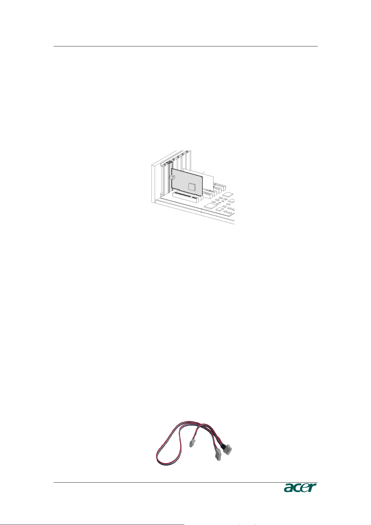
Plugging an ARMC/3P into a PCI Slot
ARMC/3P PCI
Place the ARMC/3P into a free PCI slot. You may use any PCI slot (33 or 66 MHz,
32 or 64 Bit, PCI-X).
Figure 12 Mounting the ARMC/3P into a PCI Slot
Connecting Power and Reset Cables
The ARMC/3P offers the possibility to remotely control both the power and the
reset functions of the host system. In order to support it, there is additional cabling
necessary. The preferred way for this cabling are the interfaces offered by IPMI.
However, if your host does not support IPMI you may use one of the other
possibilities.
Connecting over IPMB
This connection is used to power on or power off the system, or to perform a hard
reset. You must have a motherboard that supports IPMI 1.5 or higher and has a 3
or 4 pin IPMB connector as shown in Figure 14
o Connect the 5 pin connector of the IPMB cable with the 1x5 pin IPMB
connector on the ARMC/3P as shown in Figure 7.
o Connect the other ending of the cable with one of the IPMB connectors (3
or 4 pin connector) on the motherboard.
o Set the IPMI settings to IPMI over IPMB.
o Make sure that the IPMI function is enabled on the host system.
Figure 13 IPMB Cable
Page 24
12 P
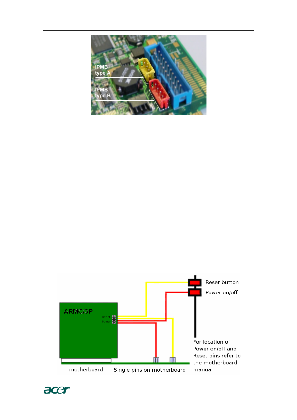
Figure 14 IPMB Connector
RODUCT USER GUIDE
Connecting to ATX Control Signals
In case your system provides separated pins for reset and power on/off, perform
the following steps while referring to Figure 7 ARMC/3P Internal Connectors.
1. Find the cable connecting the front panel reset button and the motherboard.
2. Disconnect this cable from the motherboard and connect it to RST2 of the
ARMC/3P. Refer to Figure 9 for pin assignment.
3. Take the reset cable provided with the ARMC/3P and connect one end to the
motherboard’s reset connector (from where you just disconnected the cable to
the front panel), and the other end to RST1 of the RST/PWR connector of the
ARMC/3P.
4. Find the cable connecting the front panel power button and the motherboard.
5. Disconnect this cable from the motherboard and connect it to PWR2. For pin
assignment details, refer to Figure 9.
6. Take the power cable provided with the ARMC/3P and connect one end to the
motherboard’s power connector (from where you just discon- nected the cable
to the front panel), and the other end to PWR1 of the RST/PWR connector of
the ARMC/3P.
7. Check the cabling: there are four cables connected to the RST/PWR connector,
finally.
Figure 15 Power using Reset/Power Wires
Page 25

C
HAPTER 2: INSTALLATION
13
Connecting with Front Panel Connector
There are motherboards which do not have separated pins for power on/off and
reset. Both the reset and the power buttons are placed on the system’s front panel
and connected to the motherboard via a common front panel connector. To allow
the connection of the ARMC/3P’s remote reset and power on/off signals to those
motherboards a special front panel adapter has to be placed between the front
panel connector on the motherboard and the cable connector to the front panel.
Please ask your local service center for assistance.
Connecting Power Supply
The ARMC/3P offers the possibility to be powered internally by the host system
using the ATX Power Adaptor cable or powered externally using the external
Power adaptor. (see Package Contents).
Connecting Power using ATX Power Cable Adaptor
If the host system provides an ATX 20 or ATX 24 (EPS) connection from the power
supply to the motherboard, this cable can be extended with the delivered ATX
Power Cable Adaptor. In that case the ARMC/3P is powered internally using the
5V Standby Power of the host power supply. There is no other external power
supply necessary.
For connecting the ATX Power Cable Adaptor obey the following steps while
referring to Figure 7.
1. Power off the host and disconnect it from the power line.
2. Find the ATX cable connecting the host system power supply and the
motherboard and remove the cable.
3. Exchange the disconnected cable with the delivered 20-pole ATX Power Cable
Adaptor or the 24-pole ATX Power Cable Adaptor (EPS) cable. Then, connect
the male connector of the enclosed ATX Power Cable Adaptor to the power
supply of the host system and connect the female connector of the enclosed
ATX Power Cable Adaptor to the power connector of the motherboard.
4. Connect the ATX Power Cable Adaptor male connector on the ARMC/3P with
the 5 pin female connector of the ATX Power Cable Adaptor. Refer to Figure 16
ARMC/3P Host Power pins
5. Check the cabling, finally.
Note: Powering the ARMC/3P using ATX Power Cable Adaptor solution
requires Standard ATX Power Supply with 5V/2A Standby Power. Refer to
the host system and/or power supply manual if the host system and the host
power supply fully support the ATX standard.
Page 26

14 P
Figure 16 Power using ATX Power Cable Adaptor
RODUCT USER GUIDE
Connecting Optional External Power Supply
To allow the ARMC/3P to operate independently from the server system it is
possible to connect the card to an external power supply. From the technical point
of view any power supply can be used as long as the following specifications are
met:
Table 3 Voltage and Power Specification
Parameter Value
Voltage 5V
Current >= 1A
Pinning Plus on inner connector
Dimension 2.1 mm diameter
We recommend a 5V /1A power supply. Contact your local sales representative for
an Acer approved power supply.
Important: Any standard power supply compliant with the
requirements stated above may be used. Nevertheless, any
warranty from Acer voids if non-Acer power supplies are used in
conjunction with the ARMC/3P. Check for the Acer approval label
on the external power supply in order to preserve your
manufacturer’s warranty.
Connecting Keyboard and Mouse
Keyboard and mouse data are transmitted via USB into the server system.
Connect the USB plug into the appropriate socket on the server. Local USB
keyboard and mouse could be plugged into the host directly and parallel to the
ARMC/3P VGA-USB cable.
Page 27

C
HAPTER 2: INSTALLATION
15
Connecting Ethernet
The bracket of the ARMC/3P provides a RJ45 connector for Ethernet. The connector is used either for a 100 Mbps 100Base-TX connection or for a 10 Mbps
10BASE-T connection. The adapter can sense the connection speed and will
adjust to the appropriate operation mode automatically.
10 Mbps Connection
For 10BASE-T Ethernet networks the Fast Ethernet adapter uses category 3, 4, or
5 UTP cable. To establish a 10 Mbps connection, the cable has to be connected to
a 10BASE-T hub.
1. Make sure that the cable is wired appropriately for a standard 10BASE-T
adapter.
2. Align the RJ45 plug with the notch on the adapter ’s connector and insert it into
the adapter ’s connector.
100 Mbps Connection
For 100BASE-TX Ethernet networks the ARMC/3P supports category 5 UTP
cabling. To establish a 100 Mbps connection, the cable has to be connected to a
100BASE- TX hub.
1. Make sure that the cable is wired appropriately for a standard 100BASE-TX
adapter.
2. Align the RJ45 plug with the notch on the adapter ’s connector and insert it into
the adapter ’s connector.
Important: The UTP wire pairs and configuration for 100 BASE-TX
cable are identical to those for 10 BASE-T cable when used with
category 5 UTP cable.
Page 28

Page 29

C
HAPTER 3: CONFIGURATION
17
Chapter 3: Configuration
Initial Configuration
The ARMC/3P’s communication interfaces are all based on TCP/IP. It comes
preconfigured with the IP configuration listed in Table 4 Initial Network Configuration.
Table 4 Initial Network Configuration
Parameter Value
IP auto configuration DHCP
IP address none
Netmask 255.255.255.0
Gateway none
IP access control none
Important: If the DHCP connection fails on boot up, the ARMC/3P
will not have an IP adresss.
If this initial configuration does not meet your requirements, the following describes the
initial IP configuration that is necessary to access the ARMC/3P for the first time.
ARMC/3P Psetup Tool
The psetup
DHCP server or to change the device’s initial network configuration.
tool is used to
determine
the IP addr
ess assigned to the ARMC/3P by
the
Using the Psetup Tool via Graphical User Interface
Connect the ARMC/3P to your computer via local network. Start the psetup tool,
which can be found on your ARMC/3P CD, on the computer in which the ARMC/3P
is installed or any other computer which is part of the same local network.
Note: If your network provides a properly configured DHCP server the
ARMC/3P should be automatically assigned an IP address. Please ask your
DHCP admin for the IP address the ARMC/3P got from the DHCP server.
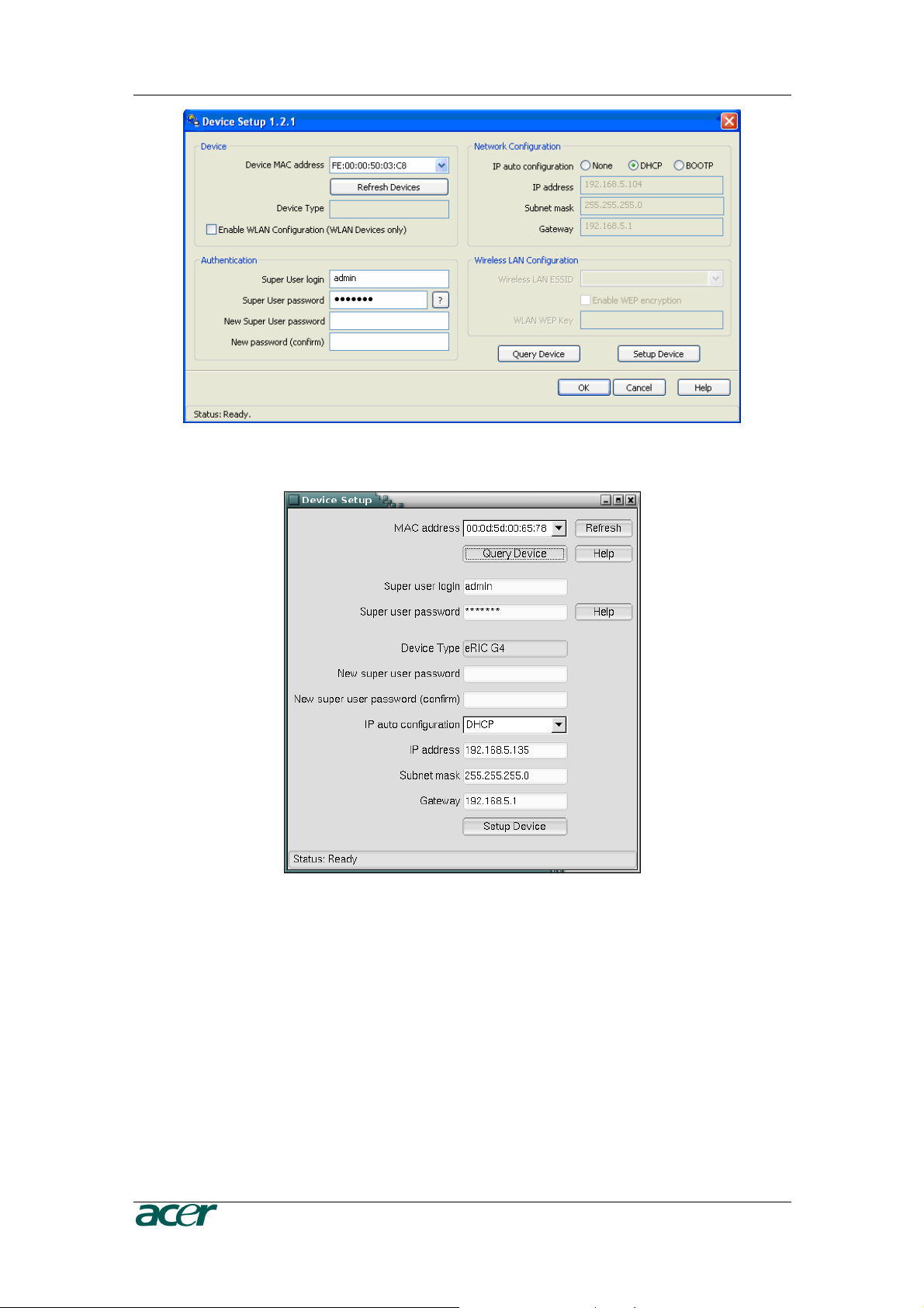
A window opens as seen in Figure 17 (on a Windows OS) and Figure 18 ARMC/3P
Psetup Tool (Linux Version).
Page 30
18 P
Figure 17 ARMC/3P Psetup Tool (Windows Version)
RODUCT USER GUIDE
Figure 18 ARMC/3P Psetup Tool (Linux Version)
Running the Linux Psetup Tool via Command Line
The following list shows the command syntax and their usage:
--mac <MAC address of the device>
Shows the current network configuration.
--ip <neue IP address>
Set a new IP address.
Page 31

C
HAPTER 3: CONFIGURATION
19
--ipacp <dhcp|bootp|none>
Set the auto configuration.
--netmask <net mask>
Set a new netmask.
--gateway <gateway address>
Set a new gateway address.
--login <username>
Admin rights are required to change the network configuration.
--pw <password>
Password of the specified above user.
--pw-new <password>
The specified above user get a new password.
An example shows the described commands and their effects:
Displaying the current network settings
test@teststation:~# /home/test/psetup --mac 00:0D:5D:00:65:78
IP auto configuration: dhcp
IP address: 192.168.5.135
Subnet mask: 255.255.255.0
Gateway: 192.168.5.1
test@teststation:~#
Changing the network settings
test@teststation:~# /home/test/psetup
--mac 00:0D:5D:00:65:78 --ipacp none
--ip 192.168.5.55 --gateway 192.168.5.1
--netmask 255.255.255.0 --login super --pw pass
Device configured successfully.
test@teststation:~#
Page 32

20 P
Mac Address Detection
Using the Psetup Tool for Windows
On the upper left corner, the MAC address of the ARMC/3P is displayed. To
detect the MAC address manually, press the button Refresh Devices. The
displayed MAC address is the same MAC address printed on the white
sticker placed on the back of the ARMC/3P. On the lower right corner of the
window, there are two buttons: Query Device and Setup Device. Press the
Query Device button to display the preconfigured values of the network
configuration. The values are displayed in the text fields located above. If
necessary, adjust the network settings to your needs. To save the changes
enter an user name and an according password. Then press the Setup
Device button.
Using the Linux Psetup Tool
On the top of the window the MAC address of the device is displayed. To
detect the MAC address manually, press the button Refresh. The displayed
MAC address is the same MAC address printed on the white sticker placed
on the back of the ARMC/3P. Furthermore, there are two buttons on the
window: Query Device and Setup Device. Press the Query Device button
to display the preconfigured values of the network configuration. The values
are displayed in the text fields located nearby. If necessary, adjust the
network settings to your needs. To save the changes enter an user name and
an according password. Then press the Setup Device button.
RODUCT USER GUIDE
Authentication
To adjust the authentication settings, enter your login as a super user and change
your password.
Super user login
Enter the login name of the super user. The initial value is “admin”.
Super user password
Enter the current password for the super user. This initial value is “password”.
New super user password
Enter the new password for the super user.
New password (confirm)
Re-type the new password for the super user.
To close the window and accept the changes press the OK button, otherwise press
the Cancel button (on Windows). On a Linux system close the window by the
appropiate button of the window frame.
Page 33

C
HAPTER 3: CONFIGURATION
21
Initial Configuration via DHCP Server
By default, the ARMC/3P will try to contact a DHCP server in the subnet to which it is
physically connected. If a DHCP server is found, it may provide a valid IP address,
gateway address and net mask. Before you connect the device to your local subnet, be
sure to complete the corresponding configuration of your DHCP server. It is
recommended to configure a fixed IP assignment to the MAC address of the ARMC/3P.
You can find the MAC address on the outside of the shipping box and on the bottom side
of the ARMC/3P. If this initial configuration does not meet your local requirements, use
the psetup tool to adjust the values to your needs. The psetup tool can be found on your
ARMC/3P CD. You can follow the procedure described below.
Initial Configuration via Serial Console
To configure the ARMC/3P via serial interface both a serial port replicator cable and a
null modem cable are required. Using a serial terminal, the ARMC/3P has a serial line
interface (rear bracket). This connector is compliant with the RS 232 serial line standard.
To establish a serial connection use a standard NULL-Modem cable. The serial line has
to be configured with the parameters given in Table 5. When configuring with a serial
terminal, reset the ARMC/3P and immediately press the ESC key. You will see some
device information, and a “=>” prompt. Enter config, press Enter and wait for a few
seconds for the configuration questions to appear.
Table 5 Serial Line Parameters
Parameter Value
Bits/second 115200
Data bits 8
Parity no
Stop bits 1
Flow control Hardware
As you proceed, the following questions will appear on the screen. To accept the default
values which are shown in square brackets below, press Enter.
IP auto configuration
IP [none]:
Net mask [255.255.255.0]:
Gateway (0.0.0.0 for none) [0.0.0.0]:
(none/dhcp/bootp) [dhcp]:
IP autoconfiguration
With this option you can specify whether the ARMC/3P should get its network
settings from a DHCP or BOOTP server. For DHCP, enter “dhcp”, and for
BOOTP enter “bootp”. If you do not specify any of these, the IP
autoconfiguration is disabled and subsequently you will be asked for the
following network settings.
Page 34

22 P
RODUCT USER GUIDE
IP address
The IP address the ARMC/3P uses. This option is only available if IP
autocon- figuration is disabled.
Net mask
The net mask of the connected IP subnet. This option is only available if IP
autoconfiguration is disabled.
Gateway address
The IP address of the default router for the connected IP subnet. If you do not
have a default router, enter 0.0.0.0. This option is only available if IP
autoconfiguration is disabled.
Finally, you will be asked if the values are correct, and may adjust them if necessary.
After your confirmation the ARMC/3P performs a reset using the new values.
Web Interface
The ARMC/3P may be accessed using a standard
use the HTTP pr
configured IP addr
otocol or a
ess of the ARMC/3P into your
secure encrypted
Java enabled
web browser. You may
connection via HTTPS. Just enter the
web browser.
The initial login
settings are:
Table 6 Standard User Settings
Parameter Value
Login admin
Password password
Changing these settings to user specific values is strongly recommended and can be
done on the “User Management” page (see Chapter 5: User and Groups).
Mouse, Keyboard and Video configuration
Between the ARMC/3P and the host, there are two interfaces available for transmitting
keyboard and mouse data: USB and PS/2. The correct operation of the remote mouse
depends on several settings which will be discussed in the following subsections.
ARMC/3P USB interface
To use the USB interface a correct cabling between the managed host and the
managing device is necessary. If the managed host has no USB keyboard support
in the BIOS and you have connected the USB cable only, then you will have no
remote keyboard access during the boot process of the host. Please see Chapter
5: Keyboard/Mouse for more details.
Page 35

C
HAPTER 3: CONFIGURATION
23
ARMC/3P Keyboard Settings
The ARMC/3P settings for the host’s keyboard type have to be correct in order to
make the remote keyboard work properly. Check the settings in the ARMC/3P
front-end. See Chapter 5: Keyboard/Mouse for details.
Remote Mouse Settings
A common problem with KVM devices is the synchronization between the local and
remote mouse cursors. The ARMC/3P addresses this situation with an intelligent
synchronization algorithm. There are three mouse modes available on the
ARMC/3P.
Auto Mouse Speed
The automatic mouse speed mode tries to detect the speed and acceleration
settings of the host system automatically. See the section below for a more
detailed explanation.
Fixed Mouse Speed
This mode just translates the mouse movements from the Remote Console in
a way that one pixel move will lead to n pixel moves on the remote system.
This parameter n is adjustable with the scaling. It should be noted that this
works only when mouse acceleration is turned off on the remote system.
Single/Double Mouse Mode
This mode is described in the Section called Single and Double Mouse Mode.
Auto Mouse Speed and Mouse Synchronization
The automatic mouse speed mode performs the speed detection during mouse
syn- chronization. Whenever the mouse does not move correctly, there are two
ways for re-synchronizing local and remote mouse:
Fast Sync
The fast synchronization is used to correct a temporary but fixed skew.
Choose this option from the Remote Console Options menu (entry: Mouse
Handling). If defined you may also press the mouse synchronization hotkey
sequence (see Chapter 4: Remote Console Control Bar details) .
Intelligent Sync
If the Fast Sync does not work or the mouse settings have been changed on
the host system, use the Intelligent Synchronization, instead. This method
adjusts the parameters for the actual movement of the mouse pointer so that
the mouse pointer is displayed at the correct position on the screen. This
method takes more time than the Fast Sync and can be accessed with the
appropriate item in the Remote Console Option menu (entry: Mouse
Handling).
The Intelligent Synchronization requires a correctly adjusted picture. Use the
Auto Adjustment function or the manual correction in the Video Settings panel
to setup the picture.
Page 36

24 P
Furthermore, the shape of the mouse pointer has a significant influence on
the pointer detection. We recommend to use a simple, but common pointer
shape. In most cases, the detection and synchronization of animated pointer
shapes is likely to fail. In general, pointer shapes that change during the
pointer detection process are rather impossible to figure out in the transferred
video picture. With the usage of a standard mouse pointer shape the
detection is rather simple and the syncronization is at its best.
Figure 19 Remote Console Control Bar: Sync Button
The Sync Mouse button on top of the Remote Console can behave
differently, depending on the current state of mouse synchronization. Usually
pressing this button leads to a Fast Sync, except in situations where the KVM
port or the video mode changed recently. See also Chapter 4: Remote
Console Control Bar.
Note: At first start, if the local mouse pointer is not synchronized with the
remote mouse pointer, press the Auto Adjust Button once.
RODUCT USER GUIDE
Host System Mouse Settings
The host’s operating system knows various settings for the mouse driver.
Important: The following limitations do not apply in case of USB
and Mouse Type “MS Windows 2000 and newer”.
While the ARMC/3P works with accelerated mice and is able to synchronize the
local with the remote mouse pointer, there are the following limitations which may
prevent this synchronization from working properly:
Special Mouse Driver
There are mouse drivers which influence the synchronization process and
lead to desynchronized mouse pointers. If this happens, make sure you do
not use a special vendor-specific mouse driver on your host system.
Windows 2003 Server/XP Mouse Settings
Windows XP knows a setting named “improve mouse acceleration” which has
to be deactivated.
Active Desktop
If the Active Desktop feature of Microsoft Windows is enabled, do not use a
plain background. Instead, use some kind of wallpaper. As an alternative, you
could also disable the Active Desktop completely.
See also the Section Recommended Mouse Settings for mouse mode
recommendations.
Page 37

C
HAPTER 3: CONFIGURATION
25
Navigate your mouse pointer into the upper left corner of the applet screen and
move it slightly forth and back. The mouse will be resynchronized. If
resynchronizing fails, disable the mouse acceleration and repeat the procedure.
Single and Double Mouse Mode
The information above applies to the Double Mouse Mode where remote and local
mouse pointers are visible and need to be synchronized. The ARMC/3P also features another mode, the Single Mouse Mode, where only the remote mouse pointer
is visible. Activate this mode in the Remote Console (see Chapter 4: Remote
Console Control Bar) and click into the window area. The local mouse pointer will
be hidden and the remote one can be controlled directly. To leave this mode it is
necessary to define a mouse hotkey in the Remote Console Settings Panel. Press
this key to free the captured local mouse pointer.
Recommended Mouse Settings
For the different operating systems on the host we can give the following advice:
MS Windows NT4
NT4 supports PS/2, only. Please choose the options PS/2 mouse and Auto
Mouse Speed.
MS Windows 2000, 2003, XP (all versions)
In general, we recommend the usage of a mouse via USB. Choose USB
without Mouse Sync. For a PS/2 mouse choose Auto Mouse Speed. For XP
disable the option “enhance pointer precision” in the Control Panel.
Note: The remote mouse is always synchronized with the local mouse if
selecting the option “MS Windows 2000 or newer”.
SUN Solaris
Adjust the mouse settings either via “xset m 1” or use the CDE Control Panel
to set the mouse to “1:1, no acceleration”. As an alternative you may also use
the Single Mouse Mode.
MAC OS X
We recommend using the Single Mouse Mode.
OS/2
We recommend using the Single Mouse Mode.
Linux
First, choose the option “Other Operating Systems” from the the Mouse Type
selection box. Second, choose the option Auto Mouse Speed. This applies for
both USB and PS/2 mice.
Note: For connecting a PS/2 mouse the PS/2 system cable is required.
Page 38

26 P
RODUCT USER GUIDE
Video Modes
The ARMC/3P recognizes a limited number of common video modes. When running X11 on the host system please do not use any custom modelines with special
video modes. If you do, the ARMC/3P may not be able to detect them. We recommend using any of the standard VESA video modes instead. Please refer to
Appendix B: ARMC/3P Video Modes for a list of all supported video modes.
Resetting the ARMC/3P to its Factory Settings
Using the S2D Pins
The ARMC/3P has two reset pins as described in Chapter 2: The Set to Default
(S2D) Pins. Upon delivery these pins are open. Close the pins with a jumper and
reboot the ARMC/3P. Wait for about two or three minutes until the primary step for
the reinitialization succeeded. Remove the jumper from the Reset Pins and reboot
the ARMC/3P, again. Now, you may use the default settings as described in
Chapter 3: The Initial Configuration.
Using the Serial Interface
Reset the ARMC/3P and immediately press the ESC key. On your screen a command prompt “=>” will be visible. Enter the command “defaults”, press the Enter
key and wait for a few seconds for the ARMC/3P to reboot. Now, you may use the
default settings as described in Chapter 3: Initial Configuration.
Figure 20 Terminal with Reset Message
Page 39

C
HAPTER 4: USAGE
27
Chapter 4: Usage
Prerequisites
The ARMC/3P features an embedded operating system and applications offering a
variety of standardized interfaces. This chapter will describe both these interfaces and
the way to use them in a more detailed manner. The interfaces are accessed using the
TCP/IP protocol family, thus they can be accessed using the built-in Ethernet adapter or
a modem, too.
The following interfaces are supported:
HTTP/HTTPS
Full access is provided by the embedded web server. The ARMC/3P environment
can be entirely managed using a standard web browser. You can access the
ARMC/3P using the insecure HTTP protocol or using the encrypted HTTPS
protocol. Whenever possible use HTTPS.
Telnet
A standard Telnet client can be used to access ay device connected to the
ARMC/3P’s serial port via a terminal mode.
SSH
The ARMC/3P also offers SSH (Secure Shell) access as a secure alternative to
Telnet.
The primary interface of the ARMC/3P is the HTTP interface. This is covered extensively
in this chapter. Other interfaces are addressed in subtopics.
In order to use the Remote Console window of your managed host system, the browser
has to come with a Java Runtime Environment version 1.1 or higher. If the browser has
no Java support (such as on a small handheld device), you are still able to maintain your
remote host system using the administration forms displayed by the browser itself.
Important: We recommend to install a Sun JVM 1.5.
For an insecure connection to the ARMC/3P we can recommend the following web
browsers:
- Microsoft Internet Explorer version 5.0 or higher on Windows 98,
Windows ME, Windows 2000 and Windows XP
- Netscape Navigator 7.0, Mozilla 1.6 and Mozilla Firefox on Windows 98,
Windows ME, Windows 2000, Windows XP, Linux and other UNIX-like
Operating Systems
In order to access the remote host system using a securely encrypted connection, you
need a browser that supports the HTTPS protocol. Strong security is only assured by
using a key length of 128 Bit. Some of the old browsers do not have a strong 128 Bit
encryption algorithm.
Page 40

28 P
RODUCT USER GUIDE
Using the Internet Explorer, open the menu entry “?” and “Info” to read about the key
length that is currently activated. The dialog box contains a link that leads you to Usage
information on how to upgrade your browser to a state of the art encryption scheme.
Figure 21 shows the dialog box presented by the Internet Explorer 6.0.
Figure 21 The Internet Explorer displaying the Encryption Key Length
Newer web browsers do support strong encryption by default.
Login into the ARMC/3P and logout
Login into the ARMC/3P
Open your web browser. Type in the address of your ARMC/3P which you configured during the installation process. The address used might be a plain IP address
or a host and domain name, in case you have given your ARMC/3P a symbolic
name in the DNS. For instance, type the following in the address line of your
browser when establishing an unsecured connection:
http://192.168.1.22/
In order to use a secure connection type in:
https://192.168.1.22/
This will lead you to the ARMC/3P login page as shown in Figure 22.
Figure 22 Login Screen
Important: Your web browser has to accept cookies or else login is
not possible.
Page 41

C
HAPTER 4: USAGE
29
The ARMC/3P has a built-in admin that has all the permissions to administer your
ARMC/3P. See the following table for the default settings.
Table 7 Standard User Settings
Parameter Value
Login admin
Password password
When you login for the first time on the ARMC/3P a window will open to request a
password change as shown in Figure 23. The password change is to prevent
unauthorized access of the host system and the ARMC/3P.
Figure 23 Password Change Request
Important: Please make sure to change the admin user password
immediately after you have installed and accessed your ARMC/3P
for the first time. Not changing the pass phrase for the admin user
is a severe security risk and might result in unauthorized access to
the ARMC/3P and to the host system including all possible
consequences!
Navigation
Having logged into the ARMC/3P successfully, the main page of the ARMC/3P
appears (see Figure 24). This page consists of three parts, each of which contains
specific information. The buttons on the upper side allow you to switch between the
different sections of the ARMC/3P (see Figure 25). The lower left frame contains
user and device information (see
right frame, task-specific information is displayed that depends on the section you
have chosen before.
錯誤
錯誤! 找不到參照來源
找不到參照來源。。。。
錯誤錯誤
找不到參照來源找不到參照來源
for details). Within the
Page 42

30 P
RODUCT USER GUIDE
Figure 24 ARMC/3P Main Page Overview
Figure 25 Navigation Frame Overview
Table 8 Links for Navigation
Link Description
Click to open the main page overview (like
Figure 24).
Click to open the KVM Console.
Important: If there is no activity for half an hour, the ARMC/3P will
log you out automatically. A click on one of the links will bring you
back to the login screen.
Page 43

C
HAPTER 4: USAGE
31
Logout from the ARMC/3P
This link logs out the current user and presents a new login screen. Please note
that an automatic logout will be performed in case there is no activity for half an
hour.
Figure 26 Logout Link
Managing the ARMC/3P with a CommandCenter
If you use CommandCenter Secure Gateway to manage your devices, then you can add
your ARMC/3P to CC-SG´s management domain to enable all CommandCenter features
for ARMC/3P. This includes single sign on and central user management and will allow
you to operate and configure the ARMC/3P directly from the CommandCenter. Please
consult your CommandCenter manual for further information on this topic.
While the ARMC/3P is managed by a CommandCenter no local access is possible.
Access and Authorization will only be granted through the CommandCenter.
Releasing the ARMC/3P from managed mode should be done with the CommandCenter.
Should the CommandCenter not be available for some reasons, then the ARMC/3P will
automatically reenable local logins after a defined time. The administrator can then
manually release the ARMC/3P from CommandCenter.
The Remote Console
General Description
The Remote Console is the redirected screen, keyboard and mouse of the remote
host system that the ARMC/3P controls.
The Remote Console window is a Java Applet that tries to establish its own TCP
connection to the ARMC/3P. The protocol that is run over this connection is neither
HTTP nor HTTPS, but RFB (Remote Frame Buffer Protocol). Currently RFB tries to
establish a connection to port #443. Your local network environment has to allow
this connection to be made, i.e. your firewall and, in case you have a private
internal network, your NAT (Network Address Translation) settings have to be
configured accordingly.
Page 44

32 P
RODUCT USER GUIDE
In case the ARMC/3P is connected to your local network environment and your
connection to the Internet is available using a proxy server only without NAT being
configured, the Remote Console is very unlikely to be able to establish the
connection. This is because today’s web proxies are not capable of relaying the
RFB protocol.
In case of problems, please consult your network administrator in order to provide
an appropriate network environment.
Figure 27 Remote Console
Main Window
Starting the Remote Console opens an additional window. It displays the screen
content of your host system. The Remote Console will behave exactly in the same
way as if you were sitting directly in front of the screen of your remote system. That
means keyboard and mouse can be used in the usual way. However, be aware of
the fact that the remote system will react to keyboard and mouse actions with a
slight delay. The delay depends on the bandwidth of the line which you use to
connect to the ARMC/3P.
With respect to the keyboard, the very exact remote representation might lead to
some confusion as your local keyboard changes its keyboard layout according to
the remote host system. If you use a German administration system and your host
system uses a US English keyboard layout, for instance, special keys on the
Page 45

C
HAPTER 4: USAGE
33
German keyboard will not work as expected. Instead, the keys will work like their
US English counterparts. You can circumvent such problems by adjusting the
keyboard of your remote system to the same mapping as your local one.
The Remote Console window always tries to show the remote screen with its
optimal size. That means it will adapt its size to the size of the remote screen
initially and after the screen resolution of the remote screen has been changed.
However, you can always resize the Remote Console window in your local window
system as usual.
Important: In difference to the remote host system, the Remote
Console window on your local window system is just one window
among others. In order to make keyboard and mouse work, your
Remote Console window must have the local input focus.
Remote Console Control Bar
The upper part of the Remote Console window contains a control bar. Using its
elements you can see the status of the Remote Console and influence the local
Remote Console settings. A description for each control follows.
Ctrl+Alt+Delete
Special button key to send the “Control Alt Delete” key combination to the
remote system (see also Chapter 5: KVM Settings for defining new button
keys).
Drive Redirection button
Menu Button for opening the Drive Redirection menu and choosing between
two virtual media options at the same time (see also Chapter 5: Drive
Redirection).
Note: The “Drive Redirection” window with the two drives for selection opens
only if the client system is using Windows 2000 or higher and if the Remote
Console user has an administrator status on Windows. In case the client
system is using a LINUX OS the “Drive Redirection Selection” window will not
be displayed.
Figure 28 Remote Console Control Bar
Auto Adjust button
If the video displayed is of bad quality or distorted in some way, press this
button and wait a few seconds while the ARMC/3P tries to adjust itself for the
best possible video quality.
Page 46

34 P
Sync Mouse
Choose this option in order to synchronize the local with the remote mouse
cursor. This is especially necessary when using accelerated mouse settings
on the host system. In general, there is no need to change mouse settings on
that.
Single/Double Mouse Mode
Switches between the Single Mouse Mode (where only the remote mouse
pointer is visible) and the Double Mouse Mode (where remote and local
mouse pointers are visible and need to be synchonized). Single Mouse Mode
is only available if using SUN JVM 1.4 or higher.
Note: If the “Host Interface” is set on “USB” and the “USB Mouse Type” is set
on “Windows >= 200, MAC OS X” then the buttons for “Sync Mouse” and
“Single/Double Mouse Mode” are hide.
Options
To open the Options menu click on the button Options. See the Section
Remote Console Options for a detailed description of the available options
for the ARMC/3P.
RODUCT USER GUIDE
Remote Console Options
To open the Options menu click on the button Options.
Figure 29 Remote Console Options Menu
A description of the options follows.
Page 47

C
HAPTER 4: USAGE
35
Monitor Only
Toggles the Monitor Only filter on or off. If the filter is switched on no remote
console interaction is possible. The remote screen can be viewed, only.
Exclusive Access
If a user has the appropriate permission, he or she can force the Remote Consoles
of all other users to close. No one can open the Remote Console at the same time
again until this user disables the exclusive access or logs off. A change in the
access mode is also visible in the status line. See the Section Remote Console
Status Line for more information.
Readability Filter
Toggles the Readability Filter on or off. If the filter is switched on in scaling mode, it
will preserve most of the screen details even if the image is substantially scaled
down. This option will be available only with a JVM 1.4 or higher.
Scaling
Allows you to scale down the Remote Console. You can still use both mouse and
keyboard, but the scaling algorithm will not preserve all display details.
Figure 30 Remote Console Options Menu: Scaling
Page 48

36 P
RODUCT USER GUIDE
Mouse Handling
The submenu for mouse handling offers two options for synchronizing the local and
the remote mouse pointer as explained in Chapter 3: Mouse, Keyboard and
Video configuration.
• Fast Sync
The fast synchronization is used to correct a temporary but fixed skew.
• Intelligent Sync
Use this option if the fast sync does not work or the mouse settings have
been changed on the host system.
• Mouse Mode
Use this option to choose between Single Mouse or Double Mouse Mode,
see Section: Remote Console Control Bar.
Important: This method takes more time than the fast one and
requires a correctly adjusted picture. To setup the picture you may
use either the auto adjustment function or the manual correction
in the Video Settings panel.
Figure 31 Remote Console Options Menu: Mouse Handling
Local Cursor
Offers a list of different cursor shapes to choose from for the local mouse pointer.
The selected shape will be saved for the current user and activated the next time
this user opens the Remote Console. The number of available shapes depends on
the Java Virtual Machine, a version of 1.2 or higher offers the full list.
Page 49

C
Chat Line
HAPTER 4: USAGE
37
Figure 32 Remote Console Options Menu: Local Cursor
Chat Window
The ARMC/3P Remote Console features a Chat Frame that allows you to communicate with other parties logged into the same card. Figure 33 Remote Console
Options Menu: Chat Window shows an example of the Chat Frame.
Title Bar
Chat Area
Figure 33 Remote Console Options Menu: Chat Window
Identity Label
The Chat Frame is helpful especially for discussing problems and questions among
the users logged into the ARMC/3P. The remote host’s screen should not be
changed or misused for that purpose.
Title Bar
Shows the IP address of the ARMC/3P you are connected to.
Page 50

38 P
RODUCT USER GUIDE
Chat Area
Read-only text area showing the messages, which have been received so far,
including your own messages sent to others. The identity string of the sender
precedes each message.
Identity Label
Shows the identity string used to precede messages sent by this Chat Frame.
The first part of the identity string is the user ID that has been used to log into
the client system, i.e. the system the browser runs on. The second part,
behind the “ @ ”, is the hostname of the client system. The last part in round
brackets is the user who logged into the ARMC/3P . As displayed in Figure
33, it is the user “super” .
Chat Line
This is an editable text line, where a new message can be entered. Once the
Enter key is hit the message is broadcasted to every other connected party.
In case a connected user has not yet opened the Chat Frame, it will be
opened automatically in order to receive and display the delivered message.
Important: Any message sent to the Chat will be broadcasted to all
connected users, which are using the Remote Console at the time
the message was sent. There is no option to direct a message to a
particular user only. The Chat has no message history. That means,
messages will be received only after opening the Remote Console.
Messages that possibly have been sent among other users will be
lost for a user who opens up his Remote Console afterwards.
Video Settings
Opens a panel for changing the ARMC/3P video settings. The ARMC/3P features
two different dialogs which influence the video settings.
Video Settings through the HTML Frontend
Select this option to enable local video port. This option decides if the local
video output of the ARMC/3P is active and passing through the incoming
signal from the host system.
The option Noise Filter defines how the ARMC/3P reacts to small changes in
the video input signal. A large filter setting needs less network traffic and
leads to a faster video display but small changes in some display regions
may not be recognized immediately. A small filter displays all changes
instantly but may lead to a constant amount of network traffic even if display
content is not really changing (depending on the quality of the video input
signal). All in all the default setting should be suitable for most situations.
Video Settings through the remote console
Page 51

C
HAPTER 4: USAGE
39
Figure 34 Remote Console Options Menu: Video Settings Panel
Brightness
Controls the brightness of the picture.
Contrast
Controls the contrast of the picture.
Clock
Defines the horizontal frequency for a video line and depends on the video
mode. Different video card types may require different values here. The
default settings in conjunction with the auto adjustment procedure should be
adequate for all common configurations. To achieve a better picture quality
you may try to change this setting together with the sampling phase.
Phase
Defines the phase for video sampling, used to control the display quality
together with the setting for sampling clock.
Horizontal Position
Use the left and right buttons to move the picture in horizontal direction while
this option is selected.
Vertical Position
Use the left and right buttons to move the picture in vertical direction while
this option is selected.
Reset this Mode
Reset mode specific settings to the factory-made defaults.
Reset all Modes
Reset all settings to the factory-made defaults.
Save changes
Save changes permanently.
Page 52

40 P
RODUCT USER GUIDE
Undo Changes
Restore last settings.
Refresh Video
Use this option to refresh the video picture. The video data for the Remote Console
is updated completely.
On startup of the Remote Console, the ARMC/3P transmits the entire video picture
from the remote host. Subsequently, the parts of the video picture that did not
change are filtered and not transmitted, again. This leads to less video data to be
transmitted. It may happen that there are parts of the video picture that are not
updated correctly (video noise, compression errors). You may use this option to
initiate an entire refresh, manually.
Soft Keyboard
The Soft Keyboard simulates an entire keyboard that is connected to the remote
system. It is necessary in case your remote system runs with a completely different
language and country mapping than your administration machine. By selecting the
appropriate button(s) you can send key codes and also key sequences to the
remote system and act as if you would work with a keyboard that is directly
connected to the remote system.
In order to open the Soft Keyboard select the entry “Soft Keyboard” from the
Options menu. You can send single key strokes like F as well as combinations of
keys such as Ctrl+C or AltGr+Shift+F4.
For a single key stroke you can click on the button with the appropriate character.
Single keys such as regular characters and numbers are sent immediately. Special
keys like Ctrl, Shift as well as the function keys F1 to F12 have to be
selected twice. The first press sends the signal “key is pressed”, the second press
sends the signal “key is released” to the remote system. After the first press the
button will change its color to indicate that the appropriate key is pressed, currently.
After the second press the button will appear as usual and indicate that the key
was sent.
To send the key combination Ctrl+C select the button Ctrl first. The button will
change its color. Press the button C. The following key (C in our example) will be
combined with the previously selected key. Both the buttons Ctrl and C are
released and the key combination will be sent to the remote system. The button
Ctrl will appear as normal (color change).
In order to send the key combination Ctrl+F5 three steps have to be taken.
Select the button Ctrl once and the button F5 twice. The last press will release
both buttons and send the key combination to the remote system.
In order to send the key combination AltGr+Shift+F4 four steps are required.
First, select the button AltGr once. Second, select the button Shift. Finally, choose
the button F4 twice. The last press will release all the buttons and send the key
combination to the remote system.
Page 53

C
HAPTER 4: USAGE
41
Figure 35 Remote Console Options Menu: Softkeyboard
• Show
Displays the Soft Keyboard.
• Mapping
Used for choosing the appropriate language and country mapping of the Soft
Keyboard.
Figure 36 Soft Keyboard Mapping
Local Keyboard
Used to change the language mapping of your browser machine running the Remote Console Applet. Normally, the applet determines the correct value automatically. However, depending on your particular JVM and your browser settings this is
not always possible. A typical example is a German localized system that uses a
US-English keyboard mapping. In this case you have to change the Local
Keyboard setting to the right language manually.
Hotkeys
Opens a list of hotkeys defined before. In order to send a registered command to
the host system choose the appropriate entry. A confirmation dialog can be added
that will be displayed before sending the selected command to the remote host.
Choose OK to perform the command on the remote host. For a detailed description
see Chapter 5: Remote Console Button Keys.
Page 54

42 P
RODUCT USER GUIDE
Figure 37 Remote Console Options Menu: Hotkey Confirmations Dialog
Encoding
These options are used to adjust the encoding level in terms of compression and
color depth. They are only available unless “Transmission Encoding” is determined
automatically (see Chapter 5: Transmission Encoding).
• Predefined
This option Predefined offers optimized data for transmission. It depends on
the bandwidth of the chosen connection.
Figure 38 Remote Console Options Menu: Encoding - Predefined
• Compression level
You may select a value between 1 and 9 for the desired compression level
with level 1 enabling the fastest compression and level 9 the best
compression. The most suitable compression level should always be seen as
a compromise between the network bandwith that is available, the video
picture to be transferred, and the number of changes between two single
video pictures. We recommend to use a higher compression level if the
network bandwidth is low. The higher the compression level the more time is
necessary to both pack and unpack the video data on either side of the
connection. The compression quality depends on the video picture itself, e.g.
Page 55

C
HAPTER 4: USAGE
43
the number of colors or the diversity of pixels. The lower the compression
quality, the more data have to be sent and the longer it may take to transfer
the whole video picture.
If level 0 is chosen the video compression is disabled, completely.
The option Video Optimized has its advantages if transferring high-quality
motion pictures. In this case the video compression is disabled, completely
and all video data is transferred via network as full-quality video snippets.
Therefore, a high amount of bandwidth is required to ensure the quality of the
video picture.
Figure 39 Remote Console Options Menu: Encoding - Compression
• Color Depth
Set the desired color depth. You may select between 8 or 16 bit for Video
Opti- mized/compression level 0, or between 1 and 8 bit for compression
level 1 to 9. The higher the color depth, the more video information has to be
captured and transferred.
Page 56

44 P
Figure 40 Remote Console Options Menu: Encoding – Color Depth
RODUCT USER GUIDE
Note: If displaying motion pictures on a connection with low speed you may
achieve an improvement regarding the video transfer rate by lowering the
color depth and disabling the option “Video Optimized”. As a general result,
the data rate is reduced (less bits per color). Furthermore, the ARMC/3P will
not have to do any video compression. In total, this will lead to less transfer
time of the motion picture.
• Lossy
Toggles the Lossy filter on or off. If the filter is switched on there will be less
data transmitted but no frames/pictures lost. That means a higher frame rate
with fewer details.
Remote Console Status Line
The status line shows both console and the connection state. On the left the size of
the remote screen is displayed. Figure 41 was taken from a Remote Console with
a resolution of 800x600 pixels (see Appendix B: ARMC/3P Video Modes for a list
of screen resolutions that can be displayed using the ARMC/3P). The value in
brackets describes the connection to the Remote Console. “Norm” means a
standard connection without encryption, “SSL” indicates a secure connection using
Secure Socket Layer (SSL).
Figure 41 Remote Console Status Line
The status line displays the number of frame buffer updates (“Fps”) as well as the
incoming (“In:”) and the outgoing (“Out:”) network traffic in kilobytes per second. A
Page 57

C
HAPTER 4: USAGE
45
low value of the network traffic is recommended and can be achieved as described
in the Section Optimizing the Video Picture. If compressed encoding is enabled,
a value in brackets displays the compressed transfer rate.
Figure 42 Status Line Transfer Rate
The next button displays the Remote Console Access settings.
Table 9 Buttons displaying the Access Status
One single user is connected to the Remote
Console of the ARMC/3P.
One or more users are connected to the Remote
Console of the ARMC/3P.
A remote user has exclusive access. You may not
access the remote host via Remote Console
unless the other user disables this option.
Exclusive access is set for you. Any other user
may not access the remote host via Remote
Console unless you disable this option.
The outer right button displays the state of the Monitor Only settings.
Table 10 Buttons displaying the Monitor State
The option Monitor Only is disabled.
The option Monitor Only is enabled.
For more information about Monitor Only and Exclusive Access settings see the
according paragraphs in the Remote Console Control Bar.
Optimizing the Video Picture
To achieve an optimal video picture for the Remote Console follow the steps as
given here:
1. Press the Auto Adjust button once (see the Section Remote Console
Control Bar for details).
Page 58

46 P
RODUCT USER GUIDE
2. Choose the option Video Settings from the Options Menu of the Remote
Console. Press the button Reset this Mode.
Figure 43 Remote Console Video Settings: Reset this Mode
3. Again, press the Auto Adjust button once.
4. The ARMC/3P detects the video mode with 8 bits (256 colors) automatically.
To improve the picture quality you may select 16 bit (True Color) from the
Options Menu of the Remote Console, sub menu “Encoding”, entry “Color
Depth” (see the Section Encoding for details).
5. Finally, if the the Remote Console transfer rate is too high you may do an
adjustment using the Noise filter. The higher the filter level the more
information is filtered from the transferred video picture (see the Section
called Video in Chapter 6 for details) and the data rate is reduced.
Currently, the video picture with the best quality can be achieved with the settings
“16 bit (High Color)” in the Remote Console or “LAN (High Color)” in the web
frontend. This option can also be preset in Chapter 5: User Console. The sub
menu “Compression” from the Options menu has no influence on the picture
quality but on the data rate of the picture that is transferred to the Remote Console.
Reducing the Noise of the Video Picture
To reduce the noise from the video picture for the Remote Console you may adjust
the Noise filter. Prior to that we recommend optimizing the video picture as
described in the Section called Optimizing the Video Picture.
In most cases the rate of transferred data indicates the noise level. The higher the
transfer rate, the higher the noise of the video picture. You may do an adjustment
using the Noise filter. The higher the filter level the more information is filtered from
the transferred video picture (see Chapter 5: Video details) and the data rate is
reduced.
Page 59

C
HAPTER 4: USAGE
47
Using the ARMC/3P with low bandwidth
The network connection of the ARMC/3P has an important influence on the time
between two single video pictures. On a connection with low bandwidth it takes
longer to transfer the video data from the ARMC/3P to the Remote Console on the
local host. If the remote screen has changed a new picture is sent.
In terms of transfer time there is no difference between text screens and screens in
graphics mode. The video picture is taken as graphics data no matter what the
screen looks like and which video mode is chosen. In terms of transferred data
there can be an improvement. The compression plays an important role here. You
can choose a compression level from the sub menu Compression in the Options
menu of the Remote Console.
Please note that the video will be compressed on the ARMC/3P, transferred to the
Remote Console and unpacked in a Java environment. Depending on the remote
host and on the local machine this procedure may take some time and may result
in a slowly updated picture in the Remote Console.
To improve the speed you may also set the picture quality in the Remote Console
to either “8 bit” or even to grayscale. Due to less video data to be processed this is
likely to be more effective than the highest compression level.
Page 60

Page 61

C
HAPTER 5: MENU OPTIONS
49
Chapter 5: Menu Options
Remote Control
KVM Console
Figure 44 Main Page with Remote Console Preview
Remote Console Preview
To open the KVM console click on the Remote Console link on the left or on the
console picture on the right, or click the Remote Control navigation button and
choose KVM Console (seen in Figure 44). To refresh the picture click on the
button that is named Refresh.
Remote Power
Use the “Remote Power” page to control the host system’s power status via one of
the following methods:
• Internal Power Control via ATX wires
• Power Control via IPMI
Page 62

50 P
RODUCT USER GUIDE
Figure 45 Power Control Overview
Internal Power Control via ATX wires
The power button is the representation of the ATX power button on your host
system. It is used to switch on and off the power supply. The ATX power button
knows two operation modes: pressing it shortly and pressing it for about 4 seconds.
Short Press
A short press on the ATX button is normally caught by the running operating
system that tries to initiate a controlled shutdown.
Usually this should always be the first action you try in case you would like to
power off your system. Only in case this is not working you should try the
long press button.
Please note that after you have pressed this button the power state displayed
in the administration panel will not immediately reflect the requested change.
A controlled shut down of the system may take some minutes. You can
observe the action caused by your button press using the Remote Console
window or by reloading the Server Power Control panel.
Long Press
This will unconditionally power off the system. Even if you have submitted a
short press before, this will shut down the power supply of the host system.
The effect of the long button press can be immediately observed on the panel
that is loaded into the browser because of the button press. The power state
will be off.
Reset
Pressing this button is similar to pressing the Reset button directly on the
remote system. Be aware that pressing the Reset button will result in an
unconditional and immediate cold start of the system. This might damage
open files and the file system itself.
Figure 46 ‘Internal Power Control’ Buttons
Page 63

C
HAPTER 5: MENU OPTIONS
51
Important: The prerequisite for the remote power/reset button to
work is a correct installation of the ARMC/3P.
Power Control via Intelligent Platform Management Interface (IPMI)
The ARMC/3P is capable of controlling the power status of an IPMI-enabled host
system. See Chapter 5: Intelligent Platform Management Interface (IPMI) for
configuration instructions. If the ARMC/3P is configured to act as an IPMI client the
Remote Power Control page will show three buttons:
Power On
Sends an IPMI “Power On” command to the Baseboard Management
Controller (BMC).
Power Off
Sends an IPMI “Power Off” command to the BMC.
Reset
Sends an IPMI “Hard Reset” command to the BMC.
Figure 47 ‘Power Control via IPMI’ Buttons
Telnet Console
The ARMC/3P firmware features a Telnet gateway that enables a user to connect
to the ARMC/3P via a standard Telnet client. For connecting to the ARMC/3P via
Telnet protocol you may use a terminal program such as xterm, TeraTerm or
Putty. As an alternative you may also enter the telnet command on the command
line or use the “Run” dialog from the Windows Start Menu. As an example you may
type the following sequence:
telnet 192.168.1.22
Replace the IP address by the one that is actually assigned to the ARMC/3P. This
will prompt for user name and password in order to log into the device. The credentials that need to be entered for authentication are identical to those of the web
interface. That means the user management of the Telnet interface is entirely
controlled with the comparable functions of the web interface.
Once you have successfully logged into the ARMC/3P a command line will be
presented and you can enter the necessarry management commands.
In general, the Telnet interface supports two operation modes: the command line
mode and the terminal mode. The command line mode is used to control or display
some parameters. In terminal mode the pass-through access to serial port 1 is acti-
Page 64

52 P
RODUCT USER GUIDE
vated (if the serial settings were made accordingly). All inputs are redirected to the
device on serial port #1 and its answers are displayed on the Telnet interface.
Figure 48 Telnet Console
The following list shows the command syntax and their usage.
help
Displays the list of possible commands
quit
Exits the current session and disconnects from the client
version
Displays the release information
terminal
Starts the terminal pass-through mode for serial port #1. The key sequence
esc exit switches back to the command mode. The command has an optional
parameter (1 or 2) to select the desired serial port for pass-through access.
reset [host|card]
Resets the given target, the host system or the ARMC/3P card. If no reset
target is given it defaults to “host”. Note that resetting the ARMC/3P results in
disconnecting every client. This includes also the client the reset command
was sent from.
power [on|off [short|long]]
The host is powered on or off. If no new power state is given, the current
Page 65

C
HAPTER 5: MENU OPTIONS
53
state will be displayed. The given attribute (either short or long) will determine
the ATX duration. The default value is short.
Voltages
Displays a list of all current voltages of the system.
Page 66

54 P
RODUCT USER GUIDE
Virtual Media
The ARMC/3P provides Double Virtual Media. So it is possible to choose between two
virtual media devices at the same time, for example required by special applications like
BOOT procedure.
Floppy Disk
Figure 49 Floppy Virtual Area
Upload a Floppy Image
With two small steps working on the basis of a certain (floppy) image can be
achieved.
• First the path of the image has to be specified. You can do that either by
hand or by using the file selection dialog of your web browser. To open the
file selection dialog click on the Browse button and select the desired image
file.
The maximum image size is limited to 1.44MB. To use a larger image mount
this image via Windows Share (or SAMBA) (see the Section called Use
Image on Windows Share (SAMBA) for details).
• Secondly, click on the Upload button to initiate the transfer of the chosen
image file into the ARMC/3P’s on-board memory. This image file is kept in the
on- board memory of the ARMC/3P until the end of the current session, until
you logged out or initiated a reboot of the ARMC/3P.
Page 67

C
HAPTER 5: MENU OPTIONS
55
Figure 50 Select Image File
Download a Floppy Image
A floppy image kept in the ARMC/3P’s memory can be both read and written to. To
retrieve the changed image contents after writing to it click the Download button
and select a folder to store the file in.
Figure 51 Active Image File
CD ROM
Use Image on Windows Share (SAMBA)
To include an image from a Windows share select CD-ROM from the submenu.
The following information has to be given to mount the selected image properly:
Share host
The server name or its IP address. On Windows 95, 98 and Windows ME do
not specify the IP address but the server name (“NetBIOS Name”).
Share name
The name of the share to be used.
Path to image
The path of the image file on the share.
User (optional)
If necessary, specify the user name for the share named before. If
Page 68

56 P
unspecified and a guest account is activated, this guest account information
will be used as your login.
Password (optional)
If necessary, specify the password for the given user name.
RODUCT USER GUIDE
Figure 52 Selecting CD-ROM and Windows Share
For an example you may have a look on Figure 52. First, the ARMC/3P will look for
a server named mysql.acme.com. Then, the entered share name is selected (in
our example we use the share storage) and the image file \cdrom_image.iso is
opened. If this file can only be accessed with both a user name and password
enter the appropriate values in the input fields for user name and password. In our
case the file is owned by the user “johndoe” and protected by a user-specific passphrase (displayed as a number of stars).
To register the specified file image and its location click on the Set button.
Page 69

C
HAPTER 5: MENU OPTIONS
57
The specified image file is supposed to be accessible from the ARMC/3P. The information above has to be given from the point of view of the ARMC/3P. It is
important to specify correct IP addresses and device names. Otherwise, the
ARMC/3P may not be able to access the referenced image file properly, leave the
given file unmounted and it will display an according error message, instead. So,
we recommend to state correct values and repeat this step if necessary.
Figure 53 The Image File on the Share
Furthermore, the specified share has to be configured correctly. Therefore, administrative permissions are required. As a regular user you may not have these permissions. You should either login as a system administrator (or as “root” on UNIX
systems) or ask your system administrator for help to complete this task.
Windows 2000/XP
Open the Explorer, navigate to the directory (or share) and press the right
mouse button to open the context menu. Select Sharing to open the
configuration dialog (see Figure 54).
Adjust the settings for the selected directory (see Figure 55).
• Activate the selected directory as a share. Select Share this folder.
• Choose an appropriate name for the share. You may also add a short
description for this folder (input field Comment).
• If necessary, adjust the permissions (button Permissions).
• Click OK to set the options for this share.
Page 70

58 P
Figure 54 Explorer Context Menu
RODUCT USER GUIDE
Figure 55 Share Configuration Dialog
Page 71

C
HAPTER 5: MENU OPTIONS
59
UNIX and UNIX-like OS (UNIX, Solaris, Linux)
If you like to access the share via SAMBA, SAMBA has to be set up properly.
You may either edit the SAMBA configuration file /etc/samba/smb.conf
or use the Samba Web Administration Tool (SWAT) or WebMin to set the
correct parameters.
For additional options see the Section: Options for details.
Drive Redirection
The Drive Redirection is another possibility to use a virtual disc drive on the remote
computer. With Drive Redirection you do not have to use an image file but may
work with a drive from your local computer on the remote machine. The drive is
hereby shared over a TCP network connection. Devices such as floppy drives,
hard discs, CD ROMs and other removable devices like USB sticks can be
redirected. It is even possible to enable a write support so that for the remote
machine it is possible to write data to your local disc.
Figure 56 Drive Redirection
Please note that Drive Redirection works on a level which is far below the
operating system. That means that neither the local nor the remote operating
system is aware that the drive is currently redirected, actually. This may lead to
inconsistent data as soon as one of the operating systems (either from the local
machine, or from the remote host) is writing data on the device. If write support is
enabled the remote computer might damage the data and the file system on the
redirected device. On the other hand, if the local operating system writes data to
the redirected device the drive cache of the operating system of the remote host
might contain older data. This may confuse the remote host’s operating system.
We recommend to use the Drive Redirection with care, especially the write support.
Drive Redirection Options
As shown in Figure 56 the following options may be enabled:
Page 72

60 P
RODUCT USER GUIDE
Disable Drive Redirection
If enabled the Drive Redirection is switched off.
Force read-only connections
If enabled the Write Support for the Drive Redirection is switched off. It is not
possible to write on a redirected device.
Click Apply to submit your changes.
Software Requirements
To use this feature, you have to install the Drive Redirection software that is
currently only available for Microsoft Windows. This software can be found on your
ARMC/3P CD.
Configuration
Figure 57 Main View
Specify the parameters of the network connection (see Figure 57).
Device
This is the address (either the DNS name or the IP address) of the ARMC/3P
you would like to connect to.
Port
This is the network port. By default, ARMC/3P uses the remote console port
(#443) here. You may change this value if you have changed the remote
console port in your ARMC/3P’s network settings.
Page 73

C
HAPTER 5: MENU OPTIONS
61
Secure Connection
Enable this box to establish a secure connection via SSL. This will maximize
the security but may reduce the connection speed.
Drive Selection
Figure 58 Selecting the desired Drive
Select the drive you would like to redirect. All available devices (drive letters) are
shown here. Please note that the whole drive is shared with the remote computer,
not only one partition. If you have a hard disc with more than one partition all drive
letters that belong to this disc will be redirected.
The Refresh button may be used to regenerate the list of drive letters, especially
for an USB stick.
Write Support
Figure 59 Selection Write Support
This feature may be enabled here. Write support means that the remote computer
is allowed to write on your local drive. As you can imagine, this is very dangerous.
If both the remote and the local system try to write data on the same device, this
will certainly destroy the file system on the drive. Please use this only when you
exactly know what you are doing.
Virtual Drive and Device Authentification
Figure 60 Device Authentification
To use the Drive Redirection, you have to authenticate on the ARMC/3P using a
valid username and password. A permission to change the virtual disc
configuration is necessary .
With the offered Double Virtual Media feature of the ARMC/3P you have to select
the drive you want to use.
Page 74

62 P
Figure 61 Virtual Drive Selection
Navigation Buttons
Connect/Disconnect
To establish the drive redirection press the Connect button once. If all the
settings are correct, the status bar displays that the connection has been
established, the Connect button is disabled and the Disconnect button is
enabled.
On an error, the status line shows the error message. The drive redirection
software tries to lock the local drive before it is redirected. That means that it
tries to prevent the local operating system from accessing the drive as long
as it is redirected. This may also fail, especially if a file on the drive is
currently open. In the case of a locking failure, you will be prompted if you
want to establish the connection anyhow. This should not be a serious
problem when the note above is respected. If the write support is enabled, a
drive which is not locked might be damaged by the Drive Redirection.
With the Disconnect button, a connection via Drive Redirection connection is
stopped.
Exit/Hide
If the Exit button is pressed, the Drive Redirection software is closed. If a
Drive Redirection connection is active, the connection will be closed before
the application terminates.
Using the Hide to Tray button the application is hidden, but not terminated
completely. That means that an active connection will be kept active until it is
closed explicitly. You can access the software by its tray icon. The tray icon
also shows whether a connection is established or not. A double click on the
icon shows the application window, or with a right click you may access a
small menu (see Figure 62).
RODUCT USER GUIDE
Figure 62 Tray Info
Options
Figure 63 USB Mass Storage Option
Page 75

C
HAPTER 5: MENU OPTIONS
63
Set this option to disable the mass storage emulation (and hide the virtual drive) as
long as no image file is currently loaded. If unset and no file image will be found, it
may happen that the host system will hang on boot due to changes in the boot
order or the boot manager (LILO, GRUB). This case was reported for some
Windows versions (2000, XP), other OS may not be fully excluded. This behaviour
depends on the BIOS version used in that machine.
To set this option press the Apply button.
Creating an Image
Floppy Images
UNIX and UNIX-like OS
To create an image file make use of “dd”. This is one of the original UNIX
utilities and is included in every UNIX-like OS (UNIX, Sun Solaris, Linux). To
create a floppy image file copy the contents of a floppy to a file. You can use
the following command:
dd [ if=/dev/fd0 ] [ of=/tmp/floppy.image ]
dd reads the entire disc from the device /dev/fd0 and saves the output in the
spec- ified output file /tmp/floppy.image. Adjust both parameters exactly
to your needs (input device etc.)
MS Windows
You can use the tool “RawWrite for Windows”.
Select the tab Read from the menu. Enter (or choose) the name of the file in
which you would like to save the floppy content. Click on the Copy button to
initiate the image creation process. For related tools you may have a look at
the homepage of the fdos project
(http://www.fdos.org/ripcord/rawrite/).
Figure 64 RawWrite for Windows Selection Dialog
Page 76

64 P
CD ROM/ISO 9660 Images
UNIX and UNIX-like OS
To create an image file make use of “dd”. This is one of the original UNIX
utilities and is included in every UNIX-like OS (UNIX, Sun Solaris, Linux). To
create a CDROM image file copy the contents of the CDROM to a file. You
can use the following command:
dd [ if=/dev/cdrom ] [ of=/tmp/cdrom.image ]
dd reads the entire disc from the device /dev/cdrom and saves the output
in the specified output file /tmp/cdrom.image. Adjust both parameters
exactly to your needs (input device etc.).
MS Windows
To create the image file use your favourite CD imaging tool. Copy the whole
contents of the disc into one single ISO image file on your harddisk. For
example, with “Nero” you choose “Copy and Backup”. Then, navigate to the
Copy Disc section. Select the CD ROM or DVD drive you would like to
create an ISO image from. Specify the filename of the ISO image and save
the CD ROM content in that file.
RODUCT USER GUIDE
Figure 65 Nero Selection Dialog
Page 77

C
HAPTER 5: MENU OPTIONS
65
System Health
The IPMI support on the host system enables you to power on or off the host
system or to perform a hard reset over the ARMC/3P. Furthermore, it provides the
possibility to show an event log of the host system and the status of some system
sensors (i.e. temperature).
Chassis Control
With Chassis Control one can
• Get the information of the specified chassis
• Switch host power on/off
• Locate host chassis
• Enable/disable the Power, Reset, NMI buttons on the front panel
Figure 66 Chassis Control
Monitor Sensors
Some of the sensors on the host will be listed here.
Page 78

66 P
Figure 67 Monitor Sensors Overview
RODUCT USER GUIDE
System Event Log
You can browse the System event logs here. Please note that these logs are for
IPMI events, they are independent to the system logs of the OPMA add-on card.
Figure 68 System Event Log Overview
Alarm Settings
Here you can see all the alerts of the system. You can also define the filters,
policies and LAN destinations, to which the alerts will be sent. For more details
please consult the IPMI specifications.
Figure 69 IPMI Alarm Configuration
Page 79

C
HAPTER 5: MENU OPTIONS
67
User Management
Change Password
Figure 70 Set Password
To change your password enter the new password in the upper entry field. Retype
the password in the field below.
Click Apply to submit your changes.
User and Groups
Figure 71 User/Group Management
Page 80

68 P
RODUCT USER GUIDE
User Management
The configurable settings of the ARMC/3P are split into user settings (basically
authentication and user information) and group settings (authorization).
There is one predefined user "admin" and two predefined group "admin" and
"<unknown>", which cannot be renamed or deleted.
Each user may be member of one group and inherits permissions set for this group.
If a user is not member of a group, permissions can be set exclusively for that user.
The user “admin” is always member of admin group which has full system access.
The <unknown> group initially does not have any permissions, but is modifiable.
Users can authenticate against a remote authentication service (such as LDAP or
RADIUS). If this remote authentication service returns an invalid or no group
assignment, the user is considered to be member of the <unknown> group.
Upon delivery, the account for the user “admin” has the password “password”.
Make sure to change the password immediately after you have installed and first
accessed your ARMC/3P.
A full list of available options follows. This list can only be seen by the admin.
Existing users
Select an existing user for modification. Once a user has been selected, click
the Lookup button to see the user information.
New User name
The new user name for the selected account.
Password
The password for the login name. It must be at least four characters long.
Confirm password
Confirmation of the password above.
Email address
This is optional.
Mobile number
This information may be optionally provided.
Dial-back number
This information may be optionally provided.
Page 81

C
HAPTER 5: MENU OPTIONS
69
Existing groups
Select an existing group for modification. Each user can be a member of a
group - either an administrator or a regular user. Choose the desired group
from the selection box.
New group name
The new group name for the selected account.
To create a user or a group press the Create button. The Modify button changes
the displayed user settings. To delete an user or group press the Delete button.
Note: The ARMC/3P is equipped with an host-independent processor and
memory unit which both have a limitation in terms of the processing
instructions and memory space. To guarantee an acceptable response time
we recommend not to exceed the number of 25 users connected to the
ARMC/3P at the same time. The memory space that is available onto the
ARMC/3P mainly depends on the configuration and the usage of the
ARMC/3P (log file entries etc.). That’s why we recommend not to store more
than 150 group profiles.
Permissions
Figure 72 User/Group Permission Settings
Here you can define the permissions for the different groups. All users of one group will
have the same rights. When you want to change the permissions for one special user
you have to define a new group for him.
Page 82

70 P
RODUCT USER GUIDE
KVM Settings
User Console
The following settings are user specific. That means the admin can customize
these settings for every user separately. Changing the settings for one user does
not affect the settings for the other users.
Figure 73 User Console Settings (Part 1)
Remote Console Settings for User
This selection box displays the user ID for which the values are shown and for
which the changes will take effect. Select the desired user from the selection box
and press the Update button. This will result in displaying the according user
settings below.
Note: You are allowed to change the settings of other users only if you have
the necessary access rights for this task. For a regular user without the
correct permissions it is not possible to change the settings for any other
users.
Transmission Encoding
The Transmission Encoding setting allows changing the image-encoding algorithm
that is used to transmit the video data to the Remote Console window. It is possible
to optimize the speed of the remote screen depending on the number of users
working at the same time and the bandwidth of the connection line (Modem, ISDN,
DSL, LAN, etc.).
Automatic detection
The encoding and the compression level is determined automatically from the
available bandwidth and the current content of the video image.
Pre-configured
The pre-configured settings deliver the best result because of optimized
adjustment of compression and color depth for the indicated network speed.
Manually
Allows to adjust both compression rate and the color depth individually.
Page 83

C
HAPTER 5: MENU OPTIONS
71
Depending on the selected compression rate the data stream between the
ARMC/3P and the Remote Console will be compressed in order to save
bandwidth. Since high compression rates are very time consuming, they
should not be used while several users are accessing the ARMC/3P
simultaneously.
The standard color depth is 16 Bit (65536 colors). The other color depths are
intended for slower network connections in order to allow a faster
transmission of data. Therefore compression level 0 (no compression) uses
only 16 Bit color depth. At lower bandwidths only 4 Bit (16 colors) and 2 Bit (4
gray scales) are recommended for typical desktop interfaces. Photo-like
pictures have best results with 4 Bit (16 gray scales). 1 Bit color depth
(black/white) should only be used for extremely slow network connections.
Remote Console Type
Figure 74 User Console Settings (Part 2)
Specifies which Remote Console Viewer to use.
Default Java Virtual Machine (JVM)
Uses the default JVM of your web browser. This may be the Microsoft JVM
for the Internet Explorer or the Sun JVM if it is configured this way. Use of the
Sun JVM may also be forced (see below).
Sun Microsystems Java Browser Plugin
Instructs the web browser of your administration system to use the JVM of
Sun Microsystems. The JVM in the browser is used to run the code for the
Remote Console window which is actually a Java Applet. If you check this
box for the first time on your administration system and the appropriate Java
Page 84

72 P
RODUCT USER GUIDE
plug-in is not yet installed on your system, it may be downloaded and
installed automatically. However, in order to make the installation possible,
you still have to answer the according dialogs with “yes”. The download
volume is around 11 Mbytes. The advantage of downloading Sun’s JVM is
the usage of a stable and identical JVM across different platforms. The
Remote Console software is optimized for this JVM version and offers a wider
range of functionality when run in SUN’s JVM.
Important: If you are connected over a slow connection to the
Internet you can also pre-install the JVM on your administration
machine.
Miscellaneous Remote Console Settings
Start in Monitor Mode
Sets the initial value for the monitor mode. By default the monitor mode is
disabled. In case you switch it on, the Remote Console window will be started
in a read only mode.
Start in Exclusive Access Mode
Enables the exclusive access mode immediately at Remote Console startup.
This forces the Remote Consoles of all other users to close. Nobody else can
open the Remote Console at the same time again until you disable this
feature or log off.
Mouse Hotkey
Allows to specify a hotkey combination which starts either the mouse
synchronization process if pressed in the Remote Console or is used to leave the
single mouse mode.
Remote Console Button Keys
Button Keys allow simulating keystrokes on the remote system that cannot be
generated locally. The reason for this might be a missing key or just the fact that
the local operating system of the Remote Console is unconditionally catching this
keystroke already. Typical examples are “Control+Alt+Delete” on Windows and
DOS, that is always caught, or the key sequence “Control+Backspace” on Linux
that can be used for terminating the X-Server.
In order to define a new Button Key or to adjust an existing one have a look at the
rules that describe the setting for a key. In general, the syntax for a key is as
follows:
[confirm] <keycode>[+|-|<[*]<keycode>]*
A term in brackets is optional. The star at the end means that you add further keys
as often as required for your case. The term “confirm” adds an confirmation
dialogue that is displayed before the key strokes will be sent to the remote host.
The “keycode” is the key to be sent. Multiple key codes can be concatenated with
either a plus, a minus, or an “<” sign. The plus sign builds key combinations - all
Page 85

C
HAPTER 5: MENU OPTIONS
73
the keys will be pressed until a minus sign or the end of the combination is
encountered. In this case all pressed keys will be released in reversed sequence.
So, the minus sign builds single, separate keypresses and keyreleases. The “<”
sign releases the last key, only. The star inserts a pause with a duration of 100
milliseconds.
As an example, the key combination of Ctrl, Alt and F2 is represented by the
sequence
Ctrl+Alt+F2
For a full list of key codes and aliases please refer to the Appendix C: Key Codes.
Key Definition
Enter your desired key combination as described above.
Name
You may also name your button that will be visible in the Remote Console
Control Bar. If unspecified the sequence of keys will be displayed, instead.
Note
If you need more button keys than shown use the more
entries button. This will open a list of additional entry fields.
Power Control
Figure 75 Power Control
The Power Control panel enables the access to the most important external
buttons of your host system besides from the keyboard. These buttons are the
reset and the power button. To enable power control by ATX/Reset wires, set this
option. Furthermore, the duration the according button is pressed can be adjusted.
Set the duration for
• ATX Reset button press
• ATX Power button short press
• ATX Power button long press
Page 86

74 P
Then, click Apply to submit your changes.
Keyboard/Mouse
RODUCT USER GUIDE
Figure 76 Keyboard and Mouse Settings
Host Interface
Enables a certain interface the mouse is connected to. You can choose between
Auto for automatic detection, USB for a USB mouse and PS/2 for a PS/2 mouse.
Important: To use the USB and/or PS/2 interface you need a correct
cabling between the managed host and the managing device. If the
managed host has no USB keyboard support in the BIOS and you
have connected the USB cable only then you will have no remote
keyboard access during the boot process of the host. If USB and
PS/2 are both connected and you selected “Auto” as host interface,
then the card will select “USB” if available or otherwise falls back
to “PS/2”.
To get USB remote keyboard access during the boot process of the host, the
following conditions must be fulfilled:
• the host BIOS must have USB keyboard support
• the USB cable must be connected or must be selected in the Host interface
option
Page 87

C
HAPTER 5: MENU OPTIONS
75
PS/2 Keyboard Model
Enables a certain keyboard layout. You can choose between “Generic 101-Key
PC” for a standard keyboard layout, “Generic 104-Key PC” for a standard keyboard
layout extended by three additional Windows keys, “Generic 106-Key PC” for a
Japanese keyboard, and “Apple Macintosh” for the Apple Macintosh.
If a keyboard timout is required the according option can be enabled. Additionally,
set the desired time value in the input field below.
USB Mouse Type
Enables the USB mouse type. Choose an appropriate option from the selection
box. For a detailed description about the mouse type and recommended options
for the different operating systems see the Section: Recommended Mouse Settings
in Chapter 3.
Mouse Speed
Auto mouse speed
Use this option if the mouse settings on the host use an additional
acceleration setting. The ARMC/3P tries to detect the acceleration and speed
of the mouse during the mouse sync process.
Fixed mouse speed
Use a direct translation of mouse movements between the local and the
remote pointer.
You may also set a fixed scaling which determines the amount the remote
mouse pointer is moved when the local mouse pointer is moved by one pixel.
This option only works when the mouse settings on the host are linear. This
means that there is no mouse acceleration involved.
To set the options click Apply.
Video
Host Monitor Settings
Using this option
which are not recognized using the factory settings. This
special modelines in a X-W
hosts or
operating systems.
screen resolution for the local monitor.
Important: This option is for advanced users only. It is possible to
influence the correct video transmission by using this option. We
recommend to use with care.
The maximum number of the custom video resolution is 4.
Modes Handling custom modes may be either disabled (
(see
Figure 77
) it is possible to add video modes to the ARMC/3P
may be useful when using
indow c
onfiguration
on
the host or with uncommon
From the selection box you may choose the desired
Using the option Custom
Off),
additionally used to
Page 88

76 P
RODUCT USER GUIDE
the standa rd video resolution or used in an
last option it is also poss
ible to force a
special video mode for the ARMC/3P. To
exclusive way (
change the parameters for a certain video mode choose the accor
the selection box and press the
Update
button. It is
additional information so that the video mode may be
X Resolution
V
isible number of horizont
al
pixels.
Y Resolution
V
isible number of vertical
pixels.
Horizontal Fr
equency (Hz
)
The horizontal (line) frequency in Hz.
V
ertical Fr
equency (Hz)
The vertical (r
efr
esh) frequency in Hz.
T
otal horizontal
The total amount of
ar
ea.
pixels
pixels
per line, including the non-v
Polarity
The polarity (positive/negative) of the
verti
cal, H means horizontal pol
arity.
synchr
onization signals. V means
Description
Here
you can provide a mode name which is displayed in the Remote
Console if this
custom mode is activ
ated.
Only). With the
ding number from
necessary to pr
ovide
correctly recognized:
isible
and
blanking
some
Page 89

C
HAPTER 5: MENU OPTIONS
77
Figure 77 Video Settings
To set the options (see below) click on the Apply button.
Miscellaneous Video Settings
Noise filter
This option defines how the ARMC/3P reacts to small changes in the video
input signal. A large filter setting needs less network traffic and leads to a
faster video display, but small changes in some display regions may not be
recognized immediately. A small filter displays all changes instantly but may
lead to a con- stant amount of network traffic even if the display content is not
really changing (depending on the quality of the video input signal). All in all
the default setting should be suitable for most situations.
Force Composite Sync (Required for Sun Computers)
To support signal transmission from a Sun machine enable this option. If not
enabled the picture of the remote console will not be visible.
Page 90

78 P
RODUCT USER GUIDE
Device Settings
Network
The Network Settings panel as shown in Figure 78 allows changing network
related parameters. Each parameter will be explained below. Once applied the new
network settings will immediately come into effect.
Figure 78 Network Settings
Important: The initial IP configuration is usually done directly at
the host system using the special procedure described in Table 4
Initial Network Configuration.
Page 91

C
HAPTER 5: MENU OPTIONS
79
Important: Changing the network settings of the ARMC/3P might
result in losing connection to it. In case you change the settings
remotely make sure that all the values are correct and you still
have an option to access the ARMC/3P.
Basic Network Settings
IP auto configuration
With this option you can define if the ARMC/3P should fetch its network
settings from a DHCP or BOOTP server. For DHCP select “dhcp” and for
BOOTP select “bootp” accordingly. If you choose “none” then IP auto
configuration is disabled.
Preferred host name
Preferred host name to request from DHCP server. Whether the DHCP
server takes the ARMC/3P’s suggestion into account or not depends on the
server configuration.
IP address
IP address in the usual dot notation.
Subnet Mask
The net mask of the local network.
Gateway IP address
In case the ARMC/3P should be accessible from networks other than the
local one, this IP address must be set to the local network router ’s IP
address.
Primary DNS Server IP Address
IP address of the primary Domain Name Server in dot notation. This option
may be left empty, however the ARMC/3P will not be able to perform name
resolution.
Secondary DNS Server IP Address
IP address of the secondary Domain Name Server in dot notation. It will be
used in case the Primary DNS Server cannot be contacted.
Miscellaneous Network Settings
Remote Console And HTTPS port
Port number at which the ARMC/3P’s Remote Console server and HTTPS
server are listening. If left empty the default value will be used.
HTTP port
Port number at which the ARMC/3P’s HTTP server is listening. If left empty
the default value will be used.
Page 92

80 P
RODUCT USER GUIDE
Telnet port
Port number at which the ARMC/3P’s Telnet server is listening. If left empty
the default value will be used.
SSH port
Port number at which the ARMC/3P’s Secure Shell (SSH) server is listening.
If left empty the default value will be used.
Bandwidth Limit
The maximum network traffic generated through the ARMC/3P Ethernet
device. Value in Kbit/s.
Enable Telnet access
Set this option to allow accessing the ARMC/3P using the Telnet gateway
(see the Chapter 5: Telnet Console).
Enable SSH access
Set this option to allow accessing the ARMC/3P using the Secure Shell (SSH)
protocol. This SSH console offers the same features as Telnet (see the
Chapter 5: Telnet Console), but uses a secure, encrypted connection
instead.
Disable Setup Protocol
Enable this option to exclude the ARMC/3P from the setup protocol.
LAN Interface Settings
This entry field displays the current settings for the Ethernet/LAN interface of the
ARMC/3P. You may choose between auto negotiation and a fixed setting for the
Ethernet transceiver settings “interface speed” and “duplex mode” in case auto
negotiation does not work correctly.
LAN interface speed
Depending on your network connection you may select an according speed
value for this interface. To adjust the interface automatically choose
“autodetect” (default value). If this selection results in misbehavior of the
interface, choose one of other speed options to work with. The interface will
transmit and receive data with that fixed speed.
LAN interface duplex mode
If necessary you may also select a specific duplex mode. The default value is
set to “autodetect” which leads to an automatic setting of the duplex mode
depend- ing on your network (recommended). As an alternative you may
explicitly set the interface to either “half duplex” or “full duplex” mode.
These settings may also be configured via serial console. See Chapter 3: Initial
Configuration via Serial Console for details.
Page 93

C
HAPTER 5: MENU OPTIONS
81
Dynamic DNS
Figure 79 Dynamic DNS
A freely available Dynamic DNS service (dyndns.org) can be used in the following
scenario (see Figure 80 Dynamic DNS Scenario):
Figure 80 Dynamic DNS Scenario
Page 94

82 P
RODUCT USER GUIDE
The ARMC/3P is reachable via the IP address of the DSL router which is dynamically assigned by the provider. Since the administrator does not know the IP
address assigned by the provider, the ARMC/3P connects to a special dynamic
DNS server in regular intervals and registers its IP address there. The
administrator may contact this server as well and pick up the same IP address
belonging to the card.
The administrator has to register an ARMC/3P that is supposed to take part in the
service with the Dynamic DNS Server and assign a certain hostname to it. He will
get a nickname and a password in return from the registration process. This
account information together with the hostname is needed in order to determine the
IP address of the registered ARMC/3P.
You have to perform the following steps in order to enable Dynamic DNS:
• Make sure that the LAN interface of the ARMC/3P is properly configured.
• Enter the Dynamic DNS Settings configuration dialog as shown in Figure 79.
• Enable Dynamic DNS and change the settings according to your needs
(see below).
Enable Dynamic DNS
This enables the Dynamic DNS service. This requires a configured DNS
server IP address.
Dynamic DNS server
This is the server name where ARMC/3P registers itself in regular intervals.
Currently this is a fixed setting since only dyndns.org is supported for now.
Hostname
This is the hostname of the ARMC/3P that is provided by the Dynamic DNS
Server (use the whole name including the domain, e.g. testserver.dyndns.org,
not just the actual hostname).
Username
You have registered this username during your manual registration with the
Dynamic DNS Server. Spaces are not allowed in the Nickname.
Password
You have used this password during your manual registration with the
Dynamic DNS Server.
Check time
The ARMC/3P card registers itself in the Dynamic DNS server at this time.
Check interval
This is the interval for reporting again to the Dynamic DNS server by the
ARMC/3P.
Important: The ARMC/3P has its own independent real time clock.
Make sure the time setting of the ARMC/3P is correct (see Chapter
5: Date/Time).
Page 95

C
HAPTER 5: MENU OPTIONS
83
Security
Figure 81 Security Settings
Encryption Settings
Force HTTPS
If this option is enabled, access to the web front-end is only possible using a
HTTPS connection. The ARMC/3P will not listen on the HTTP port for
incoming connections.
In case you want to create your own SSL certificate that is used to identify the
ARMC/3P, refer to Chapter 5: Certificate.
KVM encryption
This option controls the encryption of the RFB protocol. RFB is used by the
Page 96

84 P
Remote Console to transmit both the screen data to the administrator
machine and keyboard and mouse data back to the host.
If set to Off no encryption will be used. If set to Try the applet tries to make
an encrypted connection. If the connection cannot be established an
unencrypted connection will be used instead. If set to Force the applet tries
to make an encrypted connection. An error will be reported in case the
connection establishment fails.
IP Access Control
This
secti
on
access to a d
their IP addr
explains the settings related to IP access
istinguished number of clients only.
ess
from
which they are
trying to build up a connection.
control. It is used to limit the
These clients will be identified by
Important: The IP access control settings apply to the LAN
interface only!
Enable IP Access Contr
Enables access control
ol
based on IP source
addr
esses.
Default policy
This
option contr
any of
the configured rules. They
ols what to do
with arriving IP packets that do not match
can be accepted or dr
opped.
RODUCT USER GUIDE
Important: If you set this to “DROP” and you have no “ACCEPT”
rules configured, the access to the web front end over LAN is
actually impossible! To enable access again you can change the
security settings via modem or by temporarily disabling IP
access control with the initial configuration procedure (see
Table 4).
Rule Number
This
should
apply. In
contain
the n
umber of a r
case of appending a
ule for which
new rule,
the following
this field will be
ignor
commands will
ed.
IP/Mask
S
pecifies the IP addr
Examples (the number concatenated to an IP addr
number of
valid bits that will be used of the given IP addr
ess or IP addr
ess range for which the rule applies.
ess with a “/” is the
ess):
192.168.1.22/32
Matches
the IP Addr
ess 192.168.1.22
Matches all IP packets with sources
192.168.1.0/24
addresses from 192.168.1.0 to
192.168.1.255
0.0.0.0/0
Matches any IP packet
Page 97

C
HAPTER 5: MENU OPTIONS
85
Policy
The policy determines what to do w
either
accepted or dr
opped.
ith matching packets. They can be
Important: The order of the rules is important. The rules are
checked in ascending order until a rule matches. All the rules
below the matching one will be ignored. The default policy applies
if no match has been found.
Appending a rule
Enter the IP/Mask
and
set the
policy.
Finally, press the
Append button
.
Inserting a rule
Enter the rule number,
Insert
button
.
the IP/Mask
and
set the policy.
Finally,
press the
Replacing a rule
Enter the rule number,
Replace
button
.
the IP/Mask
and
set the policy.
Finally
, press
the
Deleting a rule
Enter the rule
number
and press the
Delete
button
.
Anti Brute Force Setting
The Anti Br
cer
tain user if
The
duration of the blocking is also configurable.
ute
his
Force
user blocking mechanism allows to disable the login of a
password
was entered
incorr
ectly
for a specific number of times.
Maximum number of failed
Enter the maximum number of failed login
not be
disable
possible for this user to login
the
user blocking feature.
logins
any
attempts after
more.
Leave this field
which it
empty to
should
Block time
The number of minutes the
num
ber of failed login
infinite
amount of time until he is manually unblocked again.
user is blocked
after he
exceeded
his
maximum
attempts. Leave this field empty to block him for an
Unblocking Users
There are two possibilties to unblock a blocked user.
• A parent user may go to the user management settings (see User
Management) and press the Unblock button for the user.
• It is also possible to use the serial console for the initial configuration (see
Table 4) and login as the user “unblock”. The ARMC/3P will ask for the
superuser password ans present a list of blocked users which may be
unblocked.
Page 98

86 P
RODUCT USER GUIDE
Login Limitations
Single Loging Limitation
If this option is enabled, the user can access the ARMC/3P only from one IP
adress with one connection. It is not possible to access the ARMC/3P from
different IP addresses or web browsers with the same login at the same time.
You have to be logged out or the session has to be timed out to get a new
connection on a different IP address on the ARMC/3P with this login.
Password Aging
If this option is enabled after a defined interval a reminder will request a new
password for the user. The set interval displays how many days the password
is active.
Certificate
The ARMC/3P uses the Secure Socket Layer (SSL) protocol for any encrypted network traffic between itself and a connected client. During the connection establishment the ARMC/3P has to expose its identity to a client using a cryptographic
certificate. Upon delivery this certificate and the underlying secret key is the same
for all ARMC/3P ever produced and certainly will not match the network configuration that will be applied to the ARMC/3P cards by its user. The certificate’s
underlying secret key is also used for securing the SSL handshake. Hence, this is
a security risk (but far better than no encryption at all).
However, it is possible to generate and install a new base64 x.509 certificate that is
unique for a particular ARMC/3P card. In order to do that, the ARMC/3P is able to
generate a new cryptographic key and the associated Certificate Signing Request
(CSR) that needs to be certified by a certification authority (CA). A certification authority verifies that you are the person who you claim you are and signs and issues
a SSL certificate to you.
Page 99

C
HAPTER 5: MENU OPTIONS
87
Figure 82 Certificate Settings
To create and install a SSL certificate for the ARMC/3P the following steps are
necessary:
• Create a SSL Certificate Signing Request using the panel shown in Figure
82. You need to fill out a number of fields that are explained below. Once
this is done, click on the Create button which will initiate the Certificate
Signing Request generation. The CSR can be downloaded to your
administration machine with the Download button (see Figure 83).
• Send the saved CSR to a CA for certification. You will get the new
certificate from the CA after a more or less complicated traditional
authentication process (depending on the CA).
• Upload the certificate to the ARMC/3P using the Upload button as shown in
Figure 83.
Page 100

88 P
RODUCT USER GUIDE
Figure 83 SSL Certificate Upload
After completing these three steps the ARMC/3P has its own certificate that is used
for identifying the card to its clients.
Important: If you destroy the CSR on the ARMC/3P there is no way
to get it back! In case you deleted it by mistake, you have to
repeat the three steps as described above.
Common name
This is the network name of the ARMC/3P once it is installed in the user’s
network (usually the fully qualified domain name). It is identical to the name
that is used to access the ARMC/3P with a web browser but without the prefix
“http://”. In case the name given here and the actual network name differ, the
browser will pop up a security warning when the ARMC/3P is accessed using
HTTPS.
Organizational unit
This field is used for specifying to which department within an organization
the ARMC/3P belongs.
Organization
The name of the organization to which the ARMC/3P belongs.
Locality/City
The city where the organization is located.
 Loading...