

Page 1

Remote
Management Card
User’s Guide
MAN-ARMC
03/03/03
Page 2

© Copyright 1998-2003 American Megatrends, Inc. for Acer, Inc.
All rights reserved.
American Megatrends, Inc.
6145-F Northbelt Parkway
Norcross, GA 30071
This publication contains proprietary information which is protected by copyright. No
part of this publication can be reproduced, transcribed, stored in a retrieval system,
translated into any language or computer language, or transmitted in any form
whatsoever without the prior written consent of the publisher, American Megatrends, Inc.
American Megatrends, Inc. acknowledges the following trademarks:
Intel is a registered trademark of the Intel Corporation.
MS-DOS and Microsoft are registered trademarks of the Microsoft Corporation.
Microsoft Windows is a trademark of the Microsoft Corporation.
IBM, AT, VGA, PS/2, and OS/2 are registered trademarks and XT and CGA are
trademarks of the International Business Machines Corporation.
Java is the trademark of Sun Microsystems Corporation.
Other trademarks and trade names may be used in this document to refer to either the
entities claiming the marks and names or their products.
Acer, Inc. disclaims any proprietary interest in trademarks and trade names other than its
own.
American Megatrends, Inc. disclaims any proprietary interest in trademarks and trade
names other than its own.
Revision History
03/03/03 Initial release.
Acer Remote Management Card (ARMC) User’s Guide
ii
Page 3

Table of Contents
Chapter 1 Introduction ................................................................................................................ 1
Features ....................................................................................................................................... 1
Chapter 2 Installing Your ARMC Card ....................................................................................... 3
Before You Start .......................................................................................................................... 3
Avoid Electro-Static Discharge (ESD)...................................................................................... 3
ARMC Installation and Setup....................................................................................................... 3
Step 1 Unpack the ARMC Card (and check jumper settings) ..................................................... 4
ARMC Card Layout .................................................................................................................. 4
ARMC MAC Address................................................................................................................4
J5 ARMC Feature Connector ................................................................................................... 5
JP2 Flash Write Enable/Disable............................................................................................... 5
JP3 ARMC Reset Button.......................................................................................................... 5
JP6 Diagnostic and Recovery Mode Jumper ........................................................................... 6
Step 2 Install the Optional Battery and Battery Clip .................................................................... 6
Installation ................................................................................................................................ 6
Charging the Battery Pack .......................................................................................................7
Storage ..................................................................................................................................... 7
Changing the Battery Pack.......................................................................................................7
Disposing of a Battery Pack .....................................................................................................8
Battery Disposal Laws.............................................................................................................. 8
Other Laws in Other Areas.......................................................................................................8
Step 3 Install the Optional Modem Daughterboard ..................................................................... 9
Step 4 Plug in the ARMC Card into the Host System and Attach Internal Cables ...................... 9
Step 5 Connect External Cables................................................................................................ 10
Step 6 Confirm the Motherboard’s BIOS Settings ..................................................................... 10
Step 7 Install the Operating System and ARMC Drivers ........................................................... 10
Step 8 Install the Acer-ARMC Windows Host Components ...................................................... 11
Step 9 Setup Your Client Internet Browser................................................................................ 15
Step 10 Connect to the ARMC from a Client System................................................................ 19
Step 11 Load the ARMC SDK File for Your Model.................................................................... 23
Chapter 3 Locating Your ARMC Card...................................................................................... 27
Overview .................................................................................................................................... 27
Locating Your ARMC Card ........................................................................................................ 27
IP Address Range...................................................................................................................... 30
Schedule Discovery ................................................................................................................... 32
Usage......................................................................................................................................... 33
Chapter 4 Using Your ARMC .................................................................................................... 35
GUI Overview............................................................................................................................. 35
Section Icons and Functions...................................................................................................... 35
Default User Name and Password ............................................................................................ 38
Welcome Screen/ Section.......................................................................................................... 38
ARMC Information ..................................................................................................................... 39
System Information .................................................................................................................... 40
Health of the ARMC Card .......................................................................................................... 41
Preface
iii
Page 4

Table of Contents
Host Health Information ............................................................................................................. 42
Loading an SDK File .............................................................................................................. 43
SDK Explained ....................................................................................................................... 46
Show Thresholds.................................................................................................................... 47
Acer 301 Thresholds Explained ............................................................................................. 48
Hide Thresholds ..................................................................................................................... 49
Deleting an SDK File .............................................................................................................. 50
Event Log ................................................................................................................................... 53
Clear Event Logs.................................................................................................................... 54
Refresh Event Logs................................................................................................................ 56
ARMC Card Management.......................................................................................................... 57
Remote Control.......................................................................................................................... 57
Remote Console ........................................................................................................................ 58
Redirection ................................................................................................................................. 59
Setting up Internet Explorer....................................................................................................59
Staring Redirection................................................................................................................. 63
Remote Console Shortcut Key Combinations........................................................................ 64
Console Redirection Window ................................................................................................. 65
Console Redirection Toolbar.................................................................................................. 68
Console Redirection Toolbar Status ...................................................................................... 68
Console Redirection Toolbar Toggle Buttons ........................................................................ 69
Setting up Virtual Floppy on Windows 2000/XP..................................................................... 70
Start Floppy Drive Redirection ............................................................................................... 73
Stop Floppy Drive Redirection................................................................................................ 75
Start CD-ROM Drive Redirection ........................................................................................... 76
Stop CD-ROM Drive Redirection ........................................................................................... 78
Stopping Console Redirection................................................................................................ 79
Crash Screen ............................................................................................................................. 80
ARMC Card Configurations ....................................................................................................... 81
Administrator Setup................................................................................................................ 82
Adding an Administrator .........................................................................................................83
Editing an Administrator ......................................................................................................... 85
Removing an Administrator .................................................................................................... 87
Networking Options ................................................................................................................ 89
Setting up Date and Time....................................................................................................... 91
Maintenance/ Flash ................................................................................................................ 92
Updating Your ARMC Card’s Firmware ................................................................................. 93
Mail Configuration .................................................................................................................. 98
Alert Recipients ...................................................................................................................... 99
Select Your Event Log Policy ............................................................................................... 100
Advanced ARMC Card Configurations .................................................................................... 101
I2C Configuration ................................................................................................................. 101
IPMI Configuration................................................................................................................ 102
Modem Configuration ........................................................................................................... 103
Host Heartbeat ..................................................................................................................... 105
ARMC Server Heartbeat ...................................................................................................... 106
Acer Remote Management Card (ARMC) User’s Guide
iv
Page 5

Table of Contents
Appendix A ARMC IPMB I2C Cable .................................................................................... 107
ARMC IPMB I2C Cable Layout................................................................................................ 107
Appendix B WinCuri, LinCuri, and RMConfigApp............................................................. 109
Overview .................................................................................................................................. 109
RMConfigApp........................................................................................................................... 109
User Manager Tab ............................................................................................................... 111
About .................................................................................................................................... 112
Network Configuration Tab................................................................................................... 113
Firmware Flash Tab ............................................................................................................. 114
Advanced Tab ...................................................................................................................... 115
Server Information Tab......................................................................................................... 116
WinCuri .................................................................................................................................... 117
WinCuri.exe Help File........................................................................................................... 117
LinCuri...................................................................................................................................... 119
LinCuri Help File................................................................................................................... 120
Appendix C ARMC Mouse Booster..................................................................................... 123
ARMC Mouse Booster ............................................................................................................. 123
Appendix D ARMC Flash Utility .......................................................................................... 125
ARMC Card Flash Utility .......................................................................................................... 125
Appendix E Troubleshooting : Screen Distortion ............................................................. 131
Problem.................................................................................................................................... 131
Solution .................................................................................................................................... 132
Appendix F Serial Over LAN ............................................................................................... 133
Hardware Setup ....................................................................................................................... 133
Internal.................................................................................................................................. 133
External ................................................................................................................................ 134
BIOS ..................................................................................................................................... 135
Connecting using Hyper Terminal ........................................................................................... 136
Appendix G Modem Daughterboard................................................................................... 139
Overview .................................................................................................................................. 139
Before You Start ...................................................................................................................... 139
Avoid Electro-Static Discharge (ESD).................................................................................. 139
Modem Daughterboard Installation.......................................................................................... 140
Modem Daughterboard Installation Illustration..................................................................... 141
Pin Alignment Illustration...................................................................................................... 141
Configuring the Modem............................................................................................................ 142
Outgoing Calls...................................................................................................................... 142
Incoming Calls...................................................................................................................... 145
Appendix H Port Usage........................................................................................................ 147
Port Usage Table ..................................................................................................................... 147
Preface
v
Page 6

Table of Contents
Appendix I ARMC MAC Address Map............................................................................... 149
Notes........................................................................................................................................ 150
Appendix J Tree Structure and Description of CD Contents .......................................... 151
ARMC CD ................................................................................................................................ 151
CD Contents......................................................................................................................... 151
Appendix K Host System USB Mouse and Keyboard Considerations for Linux 7.x..... 157
Overview .................................................................................................................................. 157
File Description ........................................................................................................................ 157
Check Your AMIBIOS Settings ................................................................................................ 157
USB Keyboard ......................................................................................................................... 157
USB Mouse.............................................................................................................................. 158
If linking to XFree86….......................................................................................................... 158
Appendix L GtkRConsoleARMC for Linux ........................................................................ 159
Installation ................................................................................................................................ 159
Index ........................................................................................................................................... 161
Acer Remote Management Card (ARMC) User’s Guide
vi
Page 7

Limitations of Liability
Acer, Inc. shall in no event be held liable for any loss, expenses, or damages of any kind
whatsoever, whether direct, indirect, incidental, or consequential (whether arising from
the design or use of this product or the support materials provided with the product). No
action or proceeding against Acer may be commenced more than two years after the
delivery of product to Licensee of Licensed Software.
Licensee agrees to defend and indemnify Acer from any and all claims, suits, and
liabilities (including attorney’s fees) arising out of or resulting from any actual or alleged
act or omission on the part of Licensee, its authorized third parties, employees, or agents,
in connection with the distribution of Licensed Software to end-users, including, without
limitation, claims, suits, and liability for bodily or other injuries to end-users resulting
from use of Licensee’s product not caused solely by faults in Licensed Software as
provided by Acer to Licensee.
Web Site
We invite you to access the Acer World Wide Web site at:
http://www.acer.com/
Preface
vii
Page 8

Disclaimer
This manual describes the operation of the Acer Remote Management Card (ARMC).
Although efforts have been made to assure the accuracy of the information contained
here, Acer expressly disclaims liability for any error in this information, and for damages,
whether direct, indirect, special, exemplary, consequential or otherwise, that may result
from such error, including but not limited to the loss of profits resulting from the use or
misuse of the manual or information contained therein (even if Acer has been advised of
the possibility of such damages). Any questions or comments regarding this document or
its contents should be addressed to Acer at the address shown on the inside of the front
cover.
Acer provides this publication “as is” without warranty of any kind, either expressed or
implied, including, but not limited to, the implied warranties of merchantability or fitness
for a specific purpose.
Some states do not allow disclaimer of express or implied warranties or the limitation or
exclusion of liability for indirect, special, exemplary, incidental or consequential
damages in certain transactions; therefore, this statement may not apply to you. Also, you
may have other rights which vary from jurisdiction to jurisdiction.
This publication could include technical inaccuracies or typographical errors. Changes
are periodically made to the information herein; these changes will be incorporated in
new editions of the publication. Acer may make improvements and/or revisions in the
product(s) and/or the program(s) described in this publication at any time.
Packing List
Requests for technical information about Acer products should be made to your Acer
authorized reseller or marketing representative.
You should have received the following:
• an Acer Remote Management Card (ARMC)
• one USB cable
• 20-pin flat ribbon cable
• external power adapter
• this Acer Remote Management Card User's Guide (located on the ARMC CD)
• an Acer Remote Management Card Quick Installation Guide
• an ARMC CD
Acer Remote Management Card (ARMC) User’s Guide
viii
Page 9

Optional Components
The following components do not come with your ARMC Card. You must order these
components separately.
• internal modem daughterboard (not designed to support Console Redirection)
• internal battery backup with battery clip
• 20-pin to 3-pin and 4-pin ARMC IPMB I2C cable
Note: The optional modem is NOT designed for Console Redirection. However, you can still
perform Console Redirection, but it is debilitating and extremely slow.
ICES-003 (Canada)
Cet appareil numérique respecte les limites bruits radioélectriques applicables aux
appareils numériques de Classe A prescrites dans la norme sur le matériel brouilleur:
“Appareils Numériques”, NMB-003 édictée par le Ministre Canadian des
Communications.
English translation of the notice above:
“This digital apparatus does not exceed the Class A limits for radio noise emissions from
digital apparatus set out in the interference-causing equipment standard entitled “Digital
Apparatus,” ICES-003 of the Canadian Department of Communications.”
BSMI (Taiwan)
The BSMI Certification number is located on the product safety label that is located on
the topside of the PCB.
D33314
Preface
ix
Page 10

Acer Remote Management Card (ARMC) User’s Guide
x
Page 11

Chapter 1 Introduction
Features
Feature Description
Key Feature
Service Processor
Remote Client
Processor
Memory
Flash
Ethernet LAN
On-Board Modem + DAA
(Optional)
I2C Controller Hardware
Monitor
Power Supply switching logic between 6 V wall adapter, 5 V PCI and optional on-board battery
Battery Backup (Optional) provides 30 minutes of battery backup in case of host system or wall adapter power
Form Factor
Environmental
Specifications
Monitoring
• 100% out-of-band
• 100% operating system independent
• provides out-of-band connectivity
• plugs into a mission critical server
• half-sized PCI form factor plugs into any PCI slot
• industry standard Internet browser (any JavaScript 1.2 capable)
• manage the server from anywhere in the world
• SSL v3 for secure connection
• 32-Bit 66 MHz ~ 60 MIPS System On Chip (SOC)
• 16 megabyte SDRAM standard (soldered on PCB, you cannot upgrade or
remove)
• four megabyte flash ROM (soldered on PCB, you cannot upgrade or remove)
• integrated SOC 10/100 MAC
• external level one 10/100 BASE-TX Ethernet
• 56K socket modem (not designed to support Console Redirection)
• ambient temperature monitoring
• PCI voltages monitoring
• battery voltage monitoring
• RTC
• external RTC for time stamp of events
failure
• half-size standard PCI card
• storage temperature: -20 degrees to 80 degrees C
• relative humidity: 5 to 80 percent non-condensing @ 40 degrees
• operating temperature: 0 to 45 degrees C
• vibration: 2.5G acceleration over 2000 Hz sine wave, 2oct/mian sine sweep
• shock: 20G; 11 msec duration, half-sine shock sweep
• IPMI 1.5 compliant
• I2C sensors
• SDK support for easy customization
• Automatic Server Recovery (ASR)
Cont’d
Chapter One : Introduction
1
Page 12

Features, Continued
Feature Description
Communication
Alert Notification
Console Redirection
Security
Virtual Boot
Host Side Operating
System Support
Server Development Kit
(SDK)
• 10/100 megabit Ethernet LAN
• 56K modem (optional, not designed to support Console Redirection)
• VPN support
• TCP/IP
• DHCP enabled
• SNMP
• web-based interface
• SNMP trap up to eight destinations
• numeric and alphanumeric paging (when optional modem is installed)
• email notification
• via 10/100 megabit Ethernet LAN
• up to 15 screens per second high speed redirection hardware engine
• no overhead on the host system, complete operating system independence
• redirect BIOS screens and setup screens
• seamless text and graphics transition
• PCI support
• SSL (Secured Socket Layer) 3.0
• DAA (Digestive Authentication Access)
• MD-5
• CD-ROM
• Floppy
• allows remote operating system boot up and installation
• Windows 2000/XP and above
• RedHat 7.3 and above
available
Acer Remote Management Card (ARMC) User’s Guide
2
Page 13

Chapter 2 Installing Your ARMC Card
Before You Start
Avoid Electro-Static Discharge (ESD)
Electro-Static Discharge (ESD) can damage the ARMC card and other system
components. Keep your ARMC card in its anti-static bag until it is to be installed.
Avoid contact with any component or connector on any adapter card, printed circuit
board, or memory module. Handle these components by the mounting bracket.
Perform all unpacking and installation procedures on a ground-connected anti-static mat.
Wear an anti-static wristband grounded at the same point as the anti-static mat. You can
also use a sheet of conductive aluminum foil grounded through a one megaohm resistor
instead of the anti-static mat. Similarly, a strip of conductive aluminum foil wrapped
around the wrist and grounded through a one megaohm resistor serves the same purpose
as a wristband.
ARMC Installation and Setup
Use the following steps to install the ARMC card into the host system.
Step Action
1 Unpack the ARMC card (and check jumper settings)
2 Install the optional battery and battery clip
3 Install the optional modem daughterboard
4 Plug in the ARMC card into the host system and attach internal cables
5 Connect external cables
6 Confirm the motherboard’s BIOS settings
7 Install the operating system and ARMC card’s display adapter drivers
8 Install all Acer-ARMC Windows Host Components
9 Setup your client system’s Internet browser
10 Connect to the ARMC from a client system
11 Load the ARMC SDK file for your model
Note: Inspect the cardboard carton for obvious damage.
Chapter Two : Installing Your ARMC Card
3
Page 14
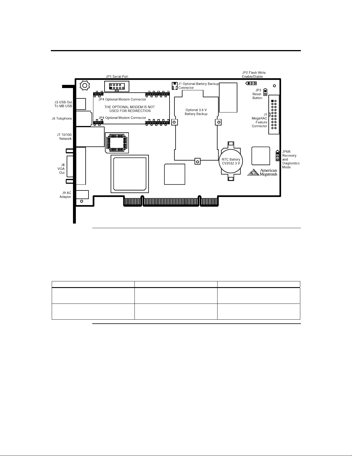
Step 1 Unpack the ARMC Card (and check jumper settings)
ARMC Card Layout
ARMC MAC Address
Your ARMC card has a unique MAC address. The MAC address is the only way to
distinguish one ARMC card from another when you run programs such as WinFlash and
RMseek. You can write down your ARMC card’s MAC address in the table below or in
Appendix I, ARMC MAC Address Map. See the first line for an example.
MAC Address Location Description
00-40-D9-02-9B-3C Server Room, Rack 2, 5
Windows 2000 Advanced
Server, Mail Server
Cont’d
Acer Remote Management Card (ARMC) User’s Guide
4
Page 15

Step 1 Unpack the ARMC Management Board (and check jumper settings),
Continued
Check the following jumpers:
Jumper Setting
JP2 Confirm that pins one and two are shorted
JP6 Confirm that pins one, two and three are open
J5 ARMC Feature Connector
This feature connector is primarily used for operating the host system’s motherboard
power and reset switch.
Note: The hardware health monitoring function requires a specific cable and Sensor Definition
Kit (SDK) file.
Pin Description Pin Description
1 Not Connected 11 Reset_Host #
2 I2C Clock 12 Ground
3 Not Connected 13 Ground
4 Not Connected 14 Not Connected
5 Power_Off # 15 Not Connected
6 I2C Data 16 Ground
7 Not Connected 17 Not Connected
8 Not Connected 18 Not Connected
9 Not Connected 19 Not Connected
10 Not Connected 20 Ground
JP2 Flash Write Enable/Disable
You can write-protect your ARMC card’s firmware so that it cannot be flashed. By
default, pins one and two are shorted so that you can flash the firmware.
Pin Description
1 VCC3
2 Write-Protect Enabled
3 Ground
Pin Description
1-2 Flash Write Enable
2-3 Flash Write Disable
JP3 ARMC Reset Button
You can short this jumper to reset your ARMC card.
Pin Description
1 Ground
2 Reset #
Cont’d
Chapter Two : Installing Your ARMC Card
5
Page 16

Step 1 Unpack the ARMC Management Board (and check jumper settings),
Continued
JP6 Diagnostic and Recovery Mode Jumper
This jumper is primarily used to recover a failed flash attempt. By shorting pins one and
two, you can place your ARMC card into Diagnostics Mode. By shorting pins two and
three, you can place your ARMC card into Recovery Mode. See Appendix D,
WinFlash.exe for more information on how to recover your ARMC card. By default, pins
one, two and three are open.
Pin Description
1 GP I/O PA7
2 Ground
3 GP I/O PA10
Step 2 Install the Optional Battery and Battery Clip
The ARMC on-board battery backup is an optional component. When the optional
battery is installed, your ARMC card can stay powered on for 28 minutes without any
external power from the host system or AC adapter.
Installation
To install the Battery Backup Unit, plug the battery cable into the J1 connector and place
the battery pack in between the three mounting holes. Next, align and snap the plastic
battery clip into the three mounting holes over the battery pack. See the diagram on the
right.
Align and snap
the battery clip
Place the battery
in between the three
mouniting holes
Plug the battery cable
into the J1 connector
into the three
mounting holes
on top side of
the PCB over the
battery backup
unit
Acer Remote Management Card (ARMC) User’s Guide
6
Cont’d
Page 17

Step 2 Install the Optional Battery and Battery Clip, Continued
Charging the Battery Pack
WARNING!
Risk of explosion if battery type used is incorrect.
ONLY use Acer battery part number BAT-LIION-3.6-01.
The optional battery pack is shipped uncharged. The ARMC card automatically starts to
charge the battery after you install it. You must charge the battery pack before it can be
used to provide backup power to the ARMC card. The minimum time that the battery
must be charged is:
Acer Part Number Description Weight Time to Charge
BAT-LIION-3.6-01 Battery, Li-Ion, 3.6 V, 855/900 mAh on-board
battery pack with mounting brackets
Note: Li-Ion has no memory effect. Lithium-ion cells offer extended cycle life when cycled at
low depth of discharge. Li-Ion batteries are specified to operate between –208C to +608C
for discharge and 08C to +408C for charge.
Storage
33 g six hours
If you keep a stock of extra ARMC batteries, store them at room temperature.
Note: The recoverable capacity of cells stored for over one year at room temperature and fully
charged is 94%. The retained capacity of these same cells is 87%. This means the selfdischarge rate for a fully charged cell is approximately 150 mAh per year or 427 uAh per
day. The self-discharge rate for cells is non-linear. A partially charged cell has a selfdischarge rate of about 80 uAh per day.
Changing the Battery Pack
The optional ARMC battery pack must be replaced every 400 cycles. Cells retain 80% of
their original capacity after 400 cycles. A cycle is defined as a full charge (4.2V)
followed by a full discharge (2.8V). Keep in mind that cycling or storing the cells at
elevated temperatures can reduce the cell capacity and cycle life. Cells discharged and
stored at low temperatures can extend the shelf life of the batteries.
Step Action
1 Bring down the operating system properly. Turn the computer power off. Remove the computer cover.
Remove the ARMC card.
2 Disconnect the battery pack cable or harness from the J1 jumper on the ARMC card.
3 Install a new battery pack and connect the new battery pack to the J1 jumper.
4 Reinstall the ARMC card into the host system.
Cont’d
Chapter Two : Installing Your ARMC Card
7
Page 18

Step 2 Install the Optional Battery and Battery Clip, Continued
Disposing of a Battery Pack
WARNING!
Do not dispose of the ARMC optional battery pack by fire. Do not mutilate the battery pack. Do not
damage it in any way. Toxic chemicals can be released if it is damaged. Do not short-circuit the battery
pack.
The material in the battery pack contains heavy metals that can contaminate the
environment. Federal, state, and local laws prohibit disposal of some rechargeable
batteries in public landfills. These batteries must be sent to a specific location for proper
disposal. Call the Rechargeable Battery Recycling Corporation at 678-419-9990 (FAX:
678-419-9986) for an authorized battery disposal site near you. For a list of battery
disposal sites, write to:
Rechargeable Battery Recycling Corporation
http://www.rbrc.org/
1000 Parkwood Circle
Suite 450
Atlanta, GA 30339
Phone: 678-419-9990
Fax: 678-419-9986
Battery Disposal Laws
IMPORTANT!
Most used Lithium-ion batteries are not classified as hazardous waste under the federal RCRA (Resource
Conservation and Recovery Act). Although Minnesota law requires that Lithium-ion batteries be labeled
“easily removable” from consumer products, and that Lithium-ion batteries must be collected by
manufacturers, the Minnesota Pollution Control Agency (MPCA) has granted a temporary exemption
from these requirements.
Other Laws in Other Areas
Acer reminds you that you must comply with all applicable battery disposal and
hazardous material handling laws and regulations in the country or other jurisdiction
where you are using an optional battery pack on the ARMC card.
Acer Remote Management Card (ARMC) User’s Guide
8
Page 19

Step 3 Install the Optional Modem Daughterboard
The ARMC modem daughterboard is an optional component. Locate JP4 on the ARMC
card. It has a series of pinholes that allow you to insert the modem daughterboard. Match
the modem daughterboard and the pin holes so that the pins align properly. Insert the
modem daughterboard by sliding it straight down into the ARMC card. See Appendix G :
Modem Daughterboard for more information.
Note: The optional modem is NOT designed for Console Redirection. However, you can still
perform Console Redirection, but it is debilitating and extremely slow.
Step 4 Plug in the ARMC Card into the Host System and Attach Internal
Cables
If you have a BMC on your serverboard, you can use the 4-pins or 3-pins IPMB I2C
connector to monitor the hardware health of the serverboard. Otherwise, please check the
location of 20-pin feature connector on your motherboard and have it connected to
ARMC card at J5.
Attach the optional ARMC feature connector to the motherboard.
Plug the ARMC card into an open 32-bit PCI slot and secure it to the chassis.
Chapter Two : Installing Your ARMC Card
9
Page 20

Step 5 Connect External Cables
• Connect the USB cable from the back of the ARMC card to the motherboard’s USB
port.
• Connect your VGA monitor.
• Connect the RJ45 LAN cable from your local network.
• Connect your phone cord from the back of the ARMC card to the telephone wall
outlet. (Only if the optional modem daughterboard is installed.)
• Connect your AC adapter.
Step 6 Confirm the Motherboard’s BIOS Settings
Power on the motherboard and enter the BIOS. Using the following table, confirm that
your motherboard’s BIOS settings are correct.
BIOS Section Setting
Boot Options> Removable Devices AMI Virtual Floppy
Boot Options> ATAPI CDROM AMI Virtual CDROM
Advanced> PCIPnP> Configuration> Legacy USB Support Enable
Save the BIOS settings and restart the computer.
Note: Make sure that your motherboard BIOS supports Legacy USB devices, USB Boot or Boot
to USB.
Note: On Acer serverboards, depress the <CTRL>, <ALT>, and <ESC> keys simultaneously to
enter the BIOS.
Step 7 Install the Operating System and ARMC Drivers
Step Action
1 Install the operating system (if applicable) on the host system.
2 (Not required in Windows 2000/XP) If prompted for the display adapter drivers, install the ARMC
management board display adapter drivers located on the ARMC CD in the VGA Drivers folder.
3 (Windows 2000/XP only) When prompted for the virtual floppy drivers, install the ARMC management
board virtual floppy drivers located on the ARMC CD in the USB Floppy folder.
Note: Virtual floppy is not supported on all versions of the ARMC card.
4 (Windows 2000/XP only) When prompted for the virtual CD-ROM drivers, install the default CD-ROM
drivers.
Note: Do not use the amivirtfl.inf when prompted to install the virtual CD-ROM drivers.
Virtual CD-ROM device does not require any special drivers. You can select the default
option Microsoft Windows provides.
The
Acer Remote Management Card (ARMC) User’s Guide
10
Page 21

Step 8 Install the Acer-ARMC Windows Host Components
Acer-ARMC Windows Host Components is a collection of four ARMC host-side
components. These programs are briefly explained in the following table:
Program Description
ARMC Mouse
Booster
RMConfigApp The RMConfigApp program allows you to configure the ARMC card from the host system or
WinCuri The WinCuri program is a command prompt-based program that you can use to configure the
ARMC Server
Heartbeat
Step Description
1 Insert your ARMC CD into the host system. The host system is the system that has the ARMC card
installed into it. Browse to the following folder and file:
CDROM\HostSide\Win32\Setup.exe
2 Double left click the Setup.exe icon to begin the installation of the Acer-ARMC Windows Host
Component.
The ARMC Mouse Booster program allows you to speedup the cursor on the host system
when you use mouse redirection during Console Redirection.
from a client system.
ARMC card. It allows you all the functionality of both the Internet browser-based Remote
Access Companion for ARMC and the RMConfigApp program.
The ARMC Server Heartbeat is installed as a service in Windows. It is used to tell whether
the operating system on the host system is operating or not. It can also detect whether the
operating system was shutdown normally or abruptly.
Follow the steps outlined in the following table to install the Acer-ARMC Windows Host
Components:
3 The Acer-ARMC Windows Host Component setup window opens. Left click the Next button.
Chapter Two : Installing Your ARMC Card
Cont’d
11
Page 22
Step 8 Install the Acer-ARMC Windows Host Components, Continued
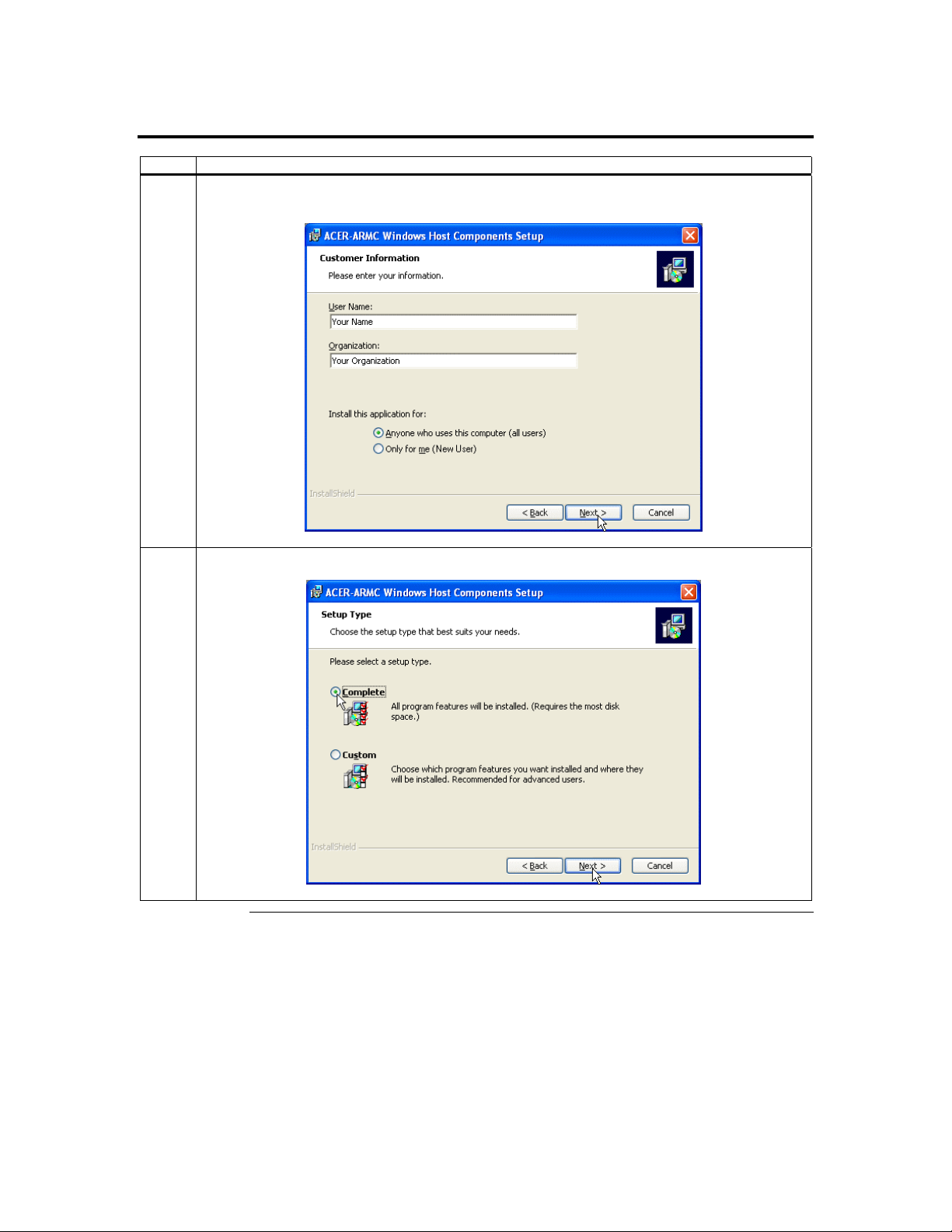
Step Description
4 The Customer Information window opens. Enter your name and your organization’s name in the
appropriate fields. Select the option for Install this application for and left click the Next button.
5 The Setup Type window opens. Select the Complete setup option. Left click the Next button.
Acer Remote Management Card (ARMC) User’s Guide
12
Cont’d
Page 23

Step 8 Install the Acer-ARMC Windows Host Components, Continued
Step Description
6 The Install Program window opens. Left click the Install button.
7 The Installation Progress window opens.
Cont’d
Chapter Two : Installing Your ARMC Card
13
Page 24

Step 8 Install the Acer-ARMC Windows Host Components, Continued
Step Description
8 The installation is complete. Left click the Finish button.
Acer Remote Management Card (ARMC) User’s Guide
14
Page 25

Step 9 Setup Your Client Internet Browser
You must first setup your Internet browser on the client system before you can redirect
the host system’s console or view the Crash screen. Follow the instructions in the table
below:
Step Description
1 Open Internet Options. To get there, open your Internet Explorer browser, left click Tools and then
Internet Options.
2 The Internet Options window opens. Left click the Settings button.
Cont’d
Chapter Two : Installing Your ARMC Card
15
Page 26

Step 9 Setup Your Client Internet Browser, Continued
Step Description
3 The Settings window opens. Left click the Every visit to the page button or Automatically button. Left
click the OK button to apply the change and to go back to the Internet Options window.
Note: Other settings can cause old data to be displayed when performing operations on the ARMC.
4 Next, you must setup Internet Explorer to allow the downloading of Signed ActiveX controls and also
allow it to run Signed ActiveX controls. To do this, left click the Security tab and then the Custom Level
button.
Acer Remote Management Card (ARMC) User’s Guide
16
Cont’d
Page 27

Step 9 Setup Your Client Internet Browser, Continued
Step Description
5 The Security Settings window opens. Left click the Enable button under the Download signed ActiveX
controls section.
6 Scroll down and left click the Enable button under the Run ActiveX controls and plug-ins section. Left
click the OK button.
Cont’d
Chapter Two : Installing Your ARMC Card
17
Page 28

Step 9 Setup Your Client Internet Browser, Continued
Step Description
7 You are prompted with a Warning window. Left click the Yes button to accept the changes to the Internet
zone and to go back to the Internet Options window.
8 Left click the Apply button and then the OK button to make the changes.
Note: You must restart Internet Explorer before the changes take effect.
Note: Remote Console cannot run with any other security settings in Internet Explorer.
Acer Remote Management Card (ARMC) User’s Guide
18
Page 29

Step 10 Connect to the ARMC from a Client System
In order to connect to the ARMC card, you must access the ARMC from another system
on the same network. This document refers to this other system as the client system. To
do this, you must know the ARMC card’s IP address. If you have installed the ARMC on
a network that uses DHCP, you can search the network for the ARMC card. To locate
and find out its IP address, you must install and run RMseek.
Note: To get or set the IP address on your ARMC card in a Windows 2000/XP environment,
you can also run the RMConfigApp program on the host system. See Appendix B,
WinCuri, LinCuri, and RMConfigApp for more information on how to use the
RMConfigApp program.
Follow the steps in the table below to connect to the ARMC from a client system:
Step Description
1
RMSeek.exe
On a local network computer, place the ARMC CD into the CD-ROM drive. Locate the RMseek program
on your ARMC CD Disc. It is located in the following directory:
CDROM\RemoteTools\Win32\RMseek.exe
Run the RMseek program by double left clicking on it.
2 Left click on the Next button when you see this screen.
Cont’d
Chapter Two : Installing Your ARMC Card
19
Page 30

Step 10 Connect to the ARMC from a Client System, Continued
Step Description
3
Type in your Network Name. In this example, Your Network is the Network Name. Next, you must
enter a range of IP addresses that you want to search. In this example, the ARMC card’s IP address is
between 192.168.0.0 to 192.168.1.0. Left click the Add>> button when finished.
4 The name and IP range of the ARMC will display in the right field. Place a check in the box next to the
range of IP addresses. Left click on the Next button.
Cont’d
Acer Remote Management Card (ARMC) User’s Guide
20
Page 31

Step 10 Connect to the ARMC from a Client System, Continued
Step Description
5 The name and IP range of the ARMC will display in the Selected IP Range window. Left click on the
Next button.
6 If the IP range is correct, RMseek will locate the ARMC card. It will list all ARMC cards it has
discovered.
Note: If more than one ARMC card is found, you can distinguish them by the ARMC card’s name.
The ARMC card’s name consists of the IP address, the letters A, R, M, and C, and the ARMC
card’s MAC address.
Cont’d
Chapter Two : Installing Your ARMC Card
21
Page 32

Step 10 Connect to the ARMC from a Client System, Continued
Step Description
7 In this example, the ARMC card’s IP address is 192.168.0.14. Double left click on the IP address to start
managing the ARMC card and write down its IP address. Left click on the Finish button after RMseek
discovers all ARMC cards.
8
When prompted for the user name and password, enter the following:
Field Default
User Name acerarmc
Password acerarmc
Left click the OK button. After you successfully log into your ARMC card, you are greeted with the
Welcome to ARMC screen.
Note: The default user name and password are in lower-case characters.
Note: When you log in using the default user name and password, you have full administrative
powers. It is advised that once you log in, you change your user name and password. See the
Administrator Setup subsection under the ARMC Configurations section of this chapter.
Acer Remote Management Card (ARMC) User’s Guide
22
Page 33

Step 11 Load the ARMC SDK File for Your Model
The following table is a pictorial description of how to load an SDK file:
Step Description
1 The quick navigation bar on the left side of the GUI has a series of section buttons. Left click on the
Information button and then left click the Host Health icon. Left click the Upload SDK File button.
2 Left click the Browse button.
Cont’d
Chapter Two : Installing Your ARMC Card
23
Page 34

Step 11 Load the ARMC SDK File for Your Model, Continued
Step Description
3
4
Insert the ARMC CD and browse to it. Select the SDKPorts directory. Select your motherboard
manufacturer. In this example, we are using the Acer Altos (G301) serverboard, so we will select the
Acer folder.
Note: The Choose File browse window differs from operating system to operating system. However,
the procedure is similar.
Select the SDK file with the DAT file extension and left click the Open button.
Acer Remote Management Card (ARMC) User’s Guide
24
Cont’d
Page 35

Step 11 Load the ARMC SDK File for Your Model, Continued
Step Description
5 Left click the Upload button.
6 Once the SDK file is uploaded, the following screen appears.
Note: If the reading displays access failed, try the following:
• If your serverboard does not have or support a BMC, check the ARMC 20-pin cable or the
3-pin or 4-pin IPMB connector to see if the cable is plugged in correctly.
• The SDK file may be corrupt. Try to upload the SDK file again.
• The SDK file you uploaded may be for a different motherboard. Make sure you are
uploaded the correct SDK file.
Chapter Two : Installing Your ARMC Card
25
Page 36

Acer Remote Management Card (ARMC) User’s Guide
26
Page 37

Chapter 3 Locating Your ARMC Card
Overview
The Acer family of server and system remote management cards can be accessed from
anywhere on your Intranet through an Internet browser. This is a great way to maintain
your critical server when you are nowhere near it.
This chapter explains how to locate your ARMC card on your local network.
Locating Your ARMC Card
In order to configure your ARMC card completely, you must access the ARMC from
another system on the same network. This document refers to this other system as a client
system. To do this, you must know the ARMC card’s IP address. If you have installed the
ARMC on a network that uses DHCP, you can search the network for the ARMC card.
To locate and find out its IP address, you must install and run RMseek.
Note: To get or set the IP address on your ARMC card in a Windows 2000/XP environment,
you can also run the RMConfigApp program on the host system. See Appendix B,
WinCuri, LinCuri, and RMConfigApp for more information on how to use the
RMConfigApp program.
Follow the steps in the table below to run RMseek:
Step Description
1
RMSeek.exe
On a local network computer, place the ARMC CD into the CD-ROM drive. Locate the RMseek program
on your ARMC CD Disc. It is located in the following directory:
CDROM\RemoteTools\Win32\RMseek.exe
Run the RMseek program by double left clicking on it.
2 Left click on the Next button when you see this screen.
Cont’d
Chapter Three : Locating Your ARMC Card
27
Page 38

Locating Your ARMC Card, Continued
Step Description
3
Type in your Network Name. In this example, Your Network is the Network Name. Next, you must
enter a range of IP addresses that you want to search. In this example, the ARMC card’s IP address is
between 192.168.0.0 to 192.168.1.0. Left click the Add>> button when finished.
4 The name and IP range of the ARMC will display in the right field. Place a check in the box next to the
range of IP addresses. Left click on the Next button.
Cont’d
Acer Remote Management Card (ARMC) User’s Guide
28
Page 39

Locating Your ARMC Card, Continued
Step Description
5 The name and IP range of the ARMC will display in the Selected IP Range window. Left click on the
Next button.
6 If the IP range is correct, RMseek will locate the ARMC card. It will list all ARMC cards it has
discovered.
Note: If more than one ARMC card is found, you can distinguish them by the ARMC card’s name.
The ARMC card’s name consists of the IP address, the letters A, R, M, and C, and the ARMC
card’s MAC address.
Cont’d
Chapter Three : Locating Your ARMC Card
29
Page 40

Locating Your ARMC Card, Continued
Step Description
7 In this example, the ARMC card’s IP address is 192.168.0.14. We can double left click on the IP to begin
managing the card or we can write down the IP and access it from an Internet browser. Left click on the
Finish button after RMseek discovers all ARMC cards.
Congratulations! You have successfully located your ARMC card.
IP Address Range
Type in a unique name for this IP range in the Network Name field. In this example,
Your Network is the Network Name. Next, you must enter a range of IP addresses that
you want to search. In this example, the ARMC card’s IP address is between 192.168.0.0
to 192.168.1.0. Left click the Add>> button when finished.
Acer Remote Management Card (ARMC) User’s Guide
30
Cont’d
Page 41

IP Address Range, Continued
Note: The Start and End IP addresses can be the same if you only wish to scan for one ARMC
card with that specific IP address.
When you have finished entering all the IP address ranges to be scanned, make sure that
they appear correctly in the list box. Confirm that the checkbox next to the IP range you
want to search is checked.
At this point, you have two options. You can choose to run the scan immediately by left
clicking on the Next button, or you can select to schedule the discovery to run at specific
times and intervals: daily, weekly, monthly or never.
The name and IP range of the ARMC card will display in the Selected IP Range window.
Left click on the Next button.
Cont’d
Chapter Three : Locating Your ARMC Card
31
Page 42

IP Address Range, Continued
If the IP range is correct, RMseek will locate the ARMC card. It will list all ARMC cards
it has discovered. Left click on the Finish button after RMseek discovers all ARMC
cards.
Schedule Discovery
To schedule a scan, left click on the Set button in the Schedule Discovery box.
Select scanning frequency desired and start time and date. Left click on the OK button.
Make sure that the IP address ranges to be scanned are checked. Left click the Cancel
button to close that page. Left click on the Finish button to close the Installation Wizard.
Schedule Discover will start at the scheduled time on those specified IP addresses ranges.
Acer Remote Management Card (ARMC) User’s Guide
32
Page 43

Usage
Once the program has been installed and setup, you can access it any time by double left
clicking on its icon on the task bar. The screen that was last viewed will appear.
Chapter Three : Locating Your ARMC Card
33
Page 44

Acer Remote Management Card (ARMC) User’s Guide
34
Page 45

Chapter 4 Using Your ARMC
GUI Overview
The ARMC has a user-friendly Graphics User Interface (GUI) called Remote Access
Companion for ARMC. It is designed to be easy to use. It has a low learning curve
because it uses a standard Internet browser. You can expect to be up and running in less
than five minutes.
This chapter allows you to become familiar with the Remote Access Companion for
ARMC’s various functions. Each function is described in detail.
Section Icons and Functions
This table allows you to become familiar with the many icons used in the GUI.
Section Icon Name Description
Welcome Acer Online This takes you to the Acer website.
Cont’d
Chapter Four : Using Your ARMC Card
35
Page 46

Section Icons and Functions, Continued
This table allows you to become familiar with the many icons used in the GUI.
Section Icon Name Description
Information
Management
System
Information
ARMC
Health
Information
Host Health This page describes the environmental parameters for the
Event Log This page contains the log of events that have occurred in the
Remote Control This page allows you to control the host system through a
Remote Console This page allows you to remotely operate the host system’s
Crash Screen This page allows you to view the last screen before a cold
This page contains general information describing the ARMC
card's firmware and the host system.
This page contains the monitored voltages on the ARMC
card. These voltages are measured both at the PCI bus
directly, and on-board the ARMC card itself.
host system based on information from an SDK file. These
parameters include, but are not limited to, ambient/
component temperatures, voltages, fan speeds, and other
chassis parameters.
host system. These events are generated due to environmental
circumstances as well as other parameters monitored
periodically by the ARMC hardware.
hardware reset or power cycle.
keyboard and mouse during a video redirection.
boot. This is useful in the event that the host system locks up
or freezes.
Cont’d
Acer Remote Management Card (ARMC) User’s Guide
36
Page 47

Section Icons and Functions, Continued
Section Icon Name Description
Configuration
Advanced
Administrators This page allows you to configure the administrators who
have access to the ARMC card.
Networking This page describes the network parameters for the ARMC
card.
Date/Time This page displays the ARMC card’s date and time. You may
also set the card's date and time by entering appropriate
values in the Set boxes and pressing Sync. For your
convenience, this system's current date and time show up by
default in the Set boxes.
Maintenance This page allows you to update your ARMC card's firmware
using an upgrade wizard.
SMTP The ARMC card uses SMTP to send out E-mail alerts and
SNMP Traps. This page configures the SMTP parameters.
The ARMC card tries the second mail server if it cannot
contact the first mail server. Some SMTP servers also require
a valid From Address to send out mails. You can use the
From address fields to specify a valid address that your mail
server will accept.
Alerts This page allows you to configure alert recipients. You can
also set the conditions necessary for the alert recipients to
receive alerts.
Event Log Policy This page allows you to set what happens when the event
logs are full. You can either set up the ARMC card to stop
logging events or roll over the log files.
I2C This page allows you to perform advanced I2C
configurations.
IPMI This page allows you to configure how the ARMC card uses
IPMI.
Modem
Configuration
Host Heartbeat This page allows you to configure the Host Heartbeat’s time
This page describes the modem configuration parameters for
the ARMC card. (not designed to support Console
Redirection)
interval. The ARMC card expects a heartbeat from the host
system after every configured elapsed time interval to
determine if the host system’s operating system is
functioning.
Chapter Four : Using Your ARMC Card
37
Page 48

Default User Name and Password
When you first try to access your ARMC card, you will be prompted to enter a user name
and password. The default user name and password are as follows:
Field Default
User Name acerarmc
Password acerarmc
Note: The default user name and password are in lower-case characters.
Note: When you log in using the default user name and password, you have full administrative
powers. It is advised that once you log in, you change your user name and password. See
the Administrator Setup subsection under the ARMC Configurations section of this
chapter.
Welcome Screen/ Section
After you successfully log into your ARMC card, you are greeted with the Welcome to
ARMC screen. The quick navigation bar on the left side of the GUI has a series of section
buttons. They are listed in the following order:
• Welcome
• Information
• Management
• Configuration
• Advanced
Cont’d
Acer Remote Management Card (ARMC) User’s Guide
38
Page 49

Welcome Screen/ Section, Continued
By clicking on a section button, you can navigate to a different section. See Section Icons
and Functions at the beginning of this chapter for a brief description of each section and
their accompanying icons and functions.
The Welcome section has one function. It is not really a function, but instead a hyperlink.
The Acer Online icon is a hyperlink to the Acer website.
ARMC Information
You can left click on the Information section button to view the ARMC card’s firmware
build and version date, health, and event log information. These functions are divided
into four subsections. The following table gives you a brief description of each. Each
subsection is explained in more detail further in this section.
Function Icon Description
View System
Information
View ARMC
Health
Information
View Host
Health
View and Clear
Event Log
This page contains general information describing the ARMC card's
firmware and the host system.
This page contains the monitored voltages on the ARMC card.
These voltages are measured both at the PCI bus directly, and onboard the ARMC card itself.
This page describes the environmental parameters for the host
based on information from an SDK file. These parameters include,
but are not limited to, ambient/ component temperatures, voltages,
fan speeds, and other chassis parameters.
This page contains the log of events that have occurred in the host
system. These events are generated due to environmental
circumstances as well as other parameters monitored periodically
by the ARMC hardware.
Chapter Four : Using Your ARMC Card
39
Page 50

System Information
The System Information screen is a subsection of the Information group. The following
table describes the information listed in this subsection in detail:
Field Description
Version Information This field gives the ARMC card’s firmware version number.
Build Date This field gives the ARMC card’s build date. It is in the following
format:
DAY MONTH DATE HOUR:MIN:SEC TIMEZONE YEAR
Host Name This field displays the name of the host system.
Host Hardware This field displays the type of hardware used for the host system.
Host Location This field displays the location of the host system.
Description This field displays a description of the host system.
ARMC card’s Name This field gives you the ARMC card’s current name.
Note: The default name is “ARMC- <the ARMC card’s
MAC address>”
Acer Remote Management Card (ARMC) User’s Guide
40
Page 51

Health of the ARMC Card
The ARMC Health Information screen is a subsection of the Information group. The
following table describes the information listed in this subsection in detail:
Field Description
ARMC Health Status
Functional This health status means that the ARMC card is
operating within normal parameters.
Warning This health status means that the ARMC card is
operating within warning parameters.
Critical This health status means that the ARMC card is
operating within critical parameters.
On Battery This health status means that the ARMC card is
operating using the on-board board battery.
Note: The on-board battery is an optional
component.
Overall Host Health
Status
ARMC 3.3V This field gives the current 3.3 V voltage reading that is measured at
ARMC 5V This field gives the current 5 V voltage reading that is measured at
PCI 12V This field gives the current PCI 12 V voltage reading that is
PCI 3.3V This field gives the current PCI 3.3 V voltage reading that is
PCI 5V This field gives the current PCI 5 V voltage reading that is measured
ARMC Wall Adapter
(6V)
Functional This health status means that the host system is
operating within normal parameters.
Warning This health status means that the host system is
operating within warning parameters.
Critical This health status means that the host system is
operating within critical parameters.
the ARMC card.
the ARMC card.
measured at the ARMC card.
measured at the ARMC card.
at the ARMC card.
This field gives the current voltage coming from the wall adapter that
is plugged into the back of the ARMC card.
Note: You can ignore this field if you do not have an AC/DC
power adapter installed.
Cont’d
Chapter Four : Using Your ARMC Card
41
Page 52

Health of the ARMC Card, Continued
The following symbols are used to indicate the health of each of the voltage fields:
Symbol Definition
Indicates that the value is within
tolerance levels.
Indicates that the value has
reached set critical levels.
Indicates that the value has
reached set warning levels.
Host Health Information
The Host Health Information screen is a subsection of the Information group. You can
load and delete a loaded Sensor Definition Kit (SDK) file from this screen. An SDK file
is a file that contains all the hardware monitoring values and thresholds for your given
motherboard. In this manual we use the Acer Altos (G301) serverboard and SDK file.
Acer Remote Management Card (ARMC) User’s Guide
42
Cont’d
Page 53

Host Health Information, Continued
Loading an SDK File
The following table is a pictorial description of how to load an SDK file:
Step Description
1 Left click the Upload SDK File button.
2 Left click the Browse button.
Cont’d
Chapter Four : Using Your ARMC Card
43
Page 54

Host Health Information, Continued
Loading an SDK File, Continued
Step Description
3
4
Insert the ARMC CD and browse to it. Select the SDKPorts directory. Select your motherboard
manufacturer. In this example, we are using the Acer Altos (G301) serverboard, so we will select the
Acer folder.
Note: The Choose File browse window differs from operating system to operating system. However,
the procedure is similar.
Select the SDK file with the DAT file extension and left click the Open button.
Acer Remote Management Card (ARMC) User’s Guide
44
Cont’d
Page 55

Host Health Information, Continued
Loading an SDK File, Continued
Step Description
5 Left click the Upload button.
6 Once the SDK file is uploaded, the following screen appears.
Note: If the reading displays access failed, try the following:
• If your serverboard does not have or support a BMC, check the ARMC 20-pin cable or the
3-pin or 4-pin IPMB connector to see if the cable is plugged in correctly.
• The SDK file may be corrupt. Try to upload the SDK file again.
• The SDK file you uploaded may be for a different motherboard. Make sure you are
uploaded the correct SDK file.
Cont’d
Chapter Four : Using Your ARMC Card
45
Page 56

Host Health Information, Continued
SDK Explained
The following table is an example of some of the fields listed:
Field Description
CPU Temperature Gives the CPU temperature reading in Celsius.
CPU Voltage Gives the CPU voltage reading.
Power Supply +3.3
Volts
Power Supply +5 Volts Gives the power supply 5 V voltage reading.
Power Supply +12
Volts
CPU Fan Gives the CPU fan’s RPM reading.
Chassis Fan Gives the chassis fan’s RPM reading.
Gives the power supply 3.3 V voltage reading.
Gives the power supply 12 V voltage reading.
The following symbols are used to indicate the health of each of the voltage fields:
Symbol Definition
Indicates that the value is within
tolerance levels.
Indicates that the value has
reached set critical levels.
Indicates that the value has
reached set warning levels.
Cont’d
Acer Remote Management Card (ARMC) User’s Guide
46
Page 57

Host Health Information, Continued
Show Thresholds
The following table is a pictorial description of how to display the hardware health
thresholds:
Step Description
1 Left click the Show Thresholds button.
2 The following screen appears.
Cont’d
Chapter Four : Using Your ARMC Card
47
Page 58

Host Health Information, Continued
Acer 301 Thresholds Explained
The following table describes the columns in the Thresholds in detail:
Column Description
Host Health Parameters This column displays the SDK parameter and graphical health icon.
Reading This column displays the current reading. For example, a
temperature, voltage, or RPM represented by a numeric value.
Low Critical This column displays the low critical warning value. When this value
is reached, an alert can be sent and an event is added to the event log.
Low Warning This column displays the low warning value. When this value is
reached, an alert can be sent and an event is added to the event log.
High Warning This column displays the high warning value. When this value is
reached, an alert can be sent and an event is added to the event log.
High Critical This column displays the high critical warning value. When this
value is reached, an alert can be sent and an event is added to the
event log.
Cont’d
Acer Remote Management Card (ARMC) User’s Guide
48
Page 59

Host Health Information, Continued
Hide Thresholds
The following table is a pictorial description of how to hide the hardware health
thresholds:
Step Description
1 Left click the Hide Thresholds button.
2 The following screen appears.
Cont’d
Chapter Four : Using Your ARMC Card
49
Page 60

Host Health Information, Continued
Deleting an SDK File
The following table is a pictorial description of how to delete an SDK file:
Step Description
1 Left click the Delete SDK File button.
2 The SDK File Delete confirmation page appears. This page allows you to delete the SDK file currently
stored on the ARMC card.
Note: Without an SDK file, host system health monitoring is not possible.
Cont’d
Acer Remote Management Card (ARMC) User’s Guide
50
Page 61

Host Health Information, Continued
Deleting an SDK File, Continued
Step Description
3 Left click the Delete Current SDK File button
4 Left click the OK button.
Cont’d
Chapter Four : Using Your ARMC Card
51
Page 62

Host Health Information, Continued
Deleting an SDK File, Continued
Step Description
5 The following screen appears.
Acer Remote Management Card (ARMC) User’s Guide
52
Page 63

Event Log
The Event Log screen is a subsection of the Information group. The following table
describes the information listed in this subsection in detail:
Column Description
Symbol Displays the symbol used to describe the current health status. See
table below.
Date Gives the date in the following format:
MM/DD/YY
Time Gives the time in the following format:
HH/MM/SS
Note: In 24-hour military time.
Code:Description Gives the error code and description of the problem or event.
Event Data Gives the event data reading.
The following symbols are used to indicate the health of each of the log events:
Symbol Definition
Indicates that the value is within
tolerance levels.
Indicates that the value has
reached set critical levels.
Indicates that the value has
reached set warning levels.
Note: Information in the system event log can be copied to the clipboard, and then pasted into
other documents, such as email messages or reports. Highlight the text you wish to copy
by left clicking and dragging the cursor. Copy the text by right clicking, and select
"copy." You may now paste the copied selection into another application using whatever
means are appropriate for your application and platform.
Cont’d
Chapter Four : Using Your ARMC Card
53
Page 64

Event Log, Continued
Clear Event Logs
This button allows you to clear all events in the log. Once the log reaches 512 events, it
cannot log any new events.
Note: The ARMC card automatically issues an alert when the logs are 75 percent full.
The following table is a pictorial description of how to clear the event logs:
Step Description
1 Left click the Clear Events button.
2 The Clear Event Log confirmation page appears with the number of events you are clearing. This page
allows you to clear the event logs stored on your ARMC card. Left click the OK button.
Cont’d
Acer Remote Management Card (ARMC) User’s Guide
54
Page 65

Event Log, Continued
Clear Event Logs, Continued
Step Description
3 The following screen appears showing that all events are cleared.
Cont’d
Chapter Four : Using Your ARMC Card
55
Page 66

Event Log, Continued
Refresh Event Logs
This button allows you to refresh the event log. The following table is a pictorial
description of how to refresh the event logs:
Step Description
1 Left click the Refresh button.
2 The event log appears with the newest list of events.
Acer Remote Management Card (ARMC) User’s Guide
56
Page 67

ARMC Card Management
You can left click on the Management section button to remotely control and redirect
your ARMC card and host system. This is the most powerful feature of the ARMC card.
These functions are divided into two subsections. The following table gives you a brief
description of each. Each subsection is explained in more detail further in this section.
Function Icon Description
Remote
Control
Remote
Console
Crash Screen This page allows you to view the last screen before a cold boot.
Remote Control
This page allows you to control the host system through a hardware
reset or power cycle.
This page allows you to remotely operate the host system’s
keyboard and mouse during a video redirection.
This is useful in the event that the host system locks up or freezes.
The Remote Control screen is a subsection of the Management group. The buttons in this
subsection generate the following results:
Button Description
Reset Generates a hardware reset signal on the host system.
Power Down Powers up the host system.
Power Up Powers up the host system.
Power Cycle Automatically generates power down followed by a power up
sequence with a pre-specified delay.
Reset ARMC Resets the ARMC card's on-board firmware.
Note: Sometimes resetting the host system cannot solve your given problem. In such cases,
power cycling the host system may overcome the problem.
Chapter Four : Using Your ARMC Card
57
Page 68

Remote Console
The Remote Console screen is a subsection of the Management group. The following
table describes the information listed in this subsection in detail:
Item Description
High Color Mode
Option
Low Color Mode
Option
Use Compression Box Place a check in this box if you want to use hardware compression.
Start Redirection Button This button allows you to start the redirection of the host system’s
This option allows the ARMC card to send 16 bits per pixel color.
This setting is recommended for faster connection speeds or over a
LAN connection. This is the default setting.
This option allows the ARMC card to send 8 bits per pixel color.
This setting is recommended for lower connection speeds or over a
WAN connection.
By default compression is not enabled. Compression can reduce the
frame rates, but increase the color output. Use compression only
when network traffic is expected to be low and graphic intensive
applications are NOT used. Best used for slower host systems.
display, keyboard and mouse. See the Redirection section in this
chapter for more information on how to use redirection. It is a
powerful feature of the ARMC card.
Note: The low color mode is recommended for low speed connections such as those over a
Wide Area Network or home DSL. If you are connecting over a LAN at high speeds you
can use the High Color Mode. In order to change modes you will have to stop redirection
and reconnect in the appropriate mode.
Acer Remote Management Card (ARMC) User’s Guide
58
Page 69

Redirection
The most powerful feature of your ARMC card is the ability to redirect the host system’s
console. To redirect the host system’s console is the ability to manage your host system
as if it were physically in front of you, but not.
Setting up Internet Explorer
You must first setup your Internet browser before you can redirect the host system’s
console.
Step Description
1 Open Internet Options. To get there, open your Internet Explorer browser, left click Tools and then
Internet Options.
2 The Internet Options window opens. Left click the Settings button.
Cont’d
Chapter Four : Using Your ARMC Card
59
Page 70

Redirection, Continued
Setting up Internet Explorer, Continued
Step Description
3 The Settings window opens. Left click the Every visit to the page button or Automatically button. Left
click the OK button to apply the change and to go back to the Internet Options window.
Note: Other settings can cause old data to be displayed when performing operations on the ARMC.
4 Next, you must setup Internet Explorer to allow the downloading of Signed ActiveX controls and also
allow it to run Signed ActiveX controls. To do this, left click the Security tab and then the Custom Level
button.
Acer Remote Management Card (ARMC) User’s Guide
60
Cont’d
Page 71

Redirection, Continued
Setting up Internet Explorer, Continued
Step Description
5 The Security Settings window opens. Left click the Enable button under the Download signed ActiveX
controls section.
6 Scroll down and left click the Enable button under the Run ActiveX controls and plug-ins section. Left
click the OK button.
Cont’d
Chapter Four : Using Your ARMC Card
61
Page 72

Redirection, Continued
Setting up Internet Explorer, Continued
Step Description
7 You are prompted with a Warning window. Left click the Yes button to accept the changes to the Internet
zone and to go back to the Internet Options window.
8 Left click the Apply button and then the OK button to make the changes.
Note: You must restart Internet Explorer before the changes take effect.
Note: Remote Console cannot run with any other security settings in Internet Explorer.
Acer Remote Management Card (ARMC) User’s Guide
62
Cont’d
Page 73

Redirection, Continued
Staring Redirection
Follow the steps in the table below to begin Console Redirection:
Step Description
1 Select the Color Mode option that you want to use. If you want to enable compression, place a check in
the box next to the Use Compression item. Left click the Start Redirection button.
2 The Remote Console Key Help window will open.
Note: The Remote Console Key Help window remains open during your Remote Console session.
After your Remote Console session is over, you can close this window by left clicking the
Close button or the upper right corner of the window.
Cont’d
Chapter Four : Using Your ARMC Card
63
Page 74

Redirection, Continued
Staring Redirection, Continued
Step Description
3 The Console Redirection window will open.
Remote Console Shortcut Key Combinations
The most powerful feature of your ARMC card is the ability to redirect the host system’s
console. To Redirect the host system’s console is the ability to manage your host system
as if it were physically in front of you, but not. The following table is a list of basic
keystrokes and their functions:
Acer Remote Management Card (ARMC) User’s Guide
64
Cont’d
Page 75

Redirection, Continued
Console Redirection Window
Dropdown
Menu Item
Console
Redirection
Description
This dropdown menu contains the following dropdown menu items:
Start Console Redirection This menu item can be used to begin Console Redirection.
Stop Console Redirection This menu item can be used to halt Console Redirection.
Restart This menu item can be used to stop Console Redirection and then
start Console Redirection again.
Full Screen This menu item can be used to view the Console Redirection in
Full Screen mode.
Note: Set your client system’s screen resolution to 1024 x
768 so that you can view the host system in true full
screen.
Sync Cursor This menu item can be used to synchronize the mouse cursor.
Note: Load the HostMouseWin.exe program to speedup
the cursor movement. See Appendix C,
HostMouseWin.exe for more information.
Start Device Redirection This menu item can be used to start redirection of the CD-ROM
drive.
Stop Device Redirection This menu item can be used to stop redirection of the CD-ROM
drive.
Cont’d
Chapter Four : Using Your ARMC Card
65
Page 76

Redirection, Continued
Console Redirection Window, Continued
Dropdown
Menu Item
Keyboard
Description
This dropdown menu contains the following dropdown menu items:
Hold Right CTRL Key This menu item can be used to act as the right-side <CTRL> key
when in Console Redirection.
Hold Right ALT Key This menu item can be used to act as the right-side <ALT> key
when in Console Redirection.
Hold Left CTRL Key This menu item can be used to act as the left-side <CTRL> key
when in Console Redirection.
Hold Left ALT Key This menu item can be used to act as the left-side <ALT> key
when in Console Redirection.
ALT+CTRL+DEL This menu item can be used to act as if you depressed the
<CTRL>, <ALT> and <DEL> keys down simultaneously on the
host system that you are redirecting.
F10 Key This menu item can be used to act as if you depressed the <F10>
key when in Console Redirection.
F11 Key This menu item can be used to act as if you depressed the <F11>
key when in Console Redirection.
F12 Key This menu item can be used to act as if you depressed the <F12>
key when in Console Redirection.
Acer Remote Management Card (ARMC) User’s Guide
66
Cont’d
Page 77

Redirection, Continued
Console Redirection Window, Continued
Dropdown
Menu Item
View This dropdown menu item contains the Toolbar menu item that allows you to start the Console
Help This dropdown menu item contains the About RConsoleOCX Control menu item that allows you to
Description
Redirection toolbar.
The following window is a screen capture of the Console Redirection toolbar.
view the RConsoleOCX Control version number and copyright information.
Cont’d
Chapter Four : Using Your ARMC Card
67
Page 78

Redirection, Continued
Console Redirection Toolbar
The Console Redirection toolbar allows you to use Console Redirection more easily in
full screen mode. The Console Redirection toolbar is a great GUI to use especially if you
are not familiar with the shortcut key combinations.
Note: Load the HostMouseWin.exe program to speedup the cursor movement. See the
HostMouseWin.exe Appendix C for more information.
Follow the steps in the table below to begin the Console Redirection toolbar:
Step Description
1 Left click the View dropdown menu. The dropdown menu will open. Left click on the Toolbar menu item.
2 The Console Redirection toolbar will open.
Console Redirection Toolbar Status
Status Item Description
Resolution This displays if you are using high or low color
mode during your redirection.
Compression This displays if you are using compression or not.
Frame Rate This displays the current frame rate you are getting.
Cont’d
Acer Remote Management Card (ARMC) User’s Guide
68
Page 79

Redirection, Continued
Console Redirection Toolbar Toggle Buttons
Icon Description
When you see this icon, it means that the Console
Redirection is on. You can left click this icon to stop
Console Redirection.
When you see this icon, it means that Console
Redirection is stopped. You can left click this icon to start
Console Redirection.
When you see this icon, it means that device redirection is
stopped. You can left click this icon to start CD-ROM
redirection.
When you see this icon, it means that CD-ROM
redirection is currently on. You can left click this icon to
stop CD-ROM redirection.
When you see this icon, it means that floppy drive
redirection is currently on. You can left click this icon to
stop floppy drive redirection.
Left click to start mouse synchronization or press the
<ALT> <M> keys.
Note: Load the HostMouseWin.exe program to
speedup the cursor movement. See the
HostMouseWin.exe Appendix C for more
information.
Left click to stop mouse synchronization or press the
<ALT> <M> keys.
Left click to view the redirected host system’s console in
full screen mode.
Note: Set your client system’s screen resolution to
1024 x 768 so that you can view the host system
in true full screen.
Left click to view the redirected host system’s console in
a window.
Left click to toggle the use of the <CTRL> key.
Left click to toggle the use of the <ALT> key.
Left click to use the <CTRL> <ALT> <DEL> keys
together.
Cont’d
Chapter Four : Using Your ARMC Card
69
Page 80

Redirection, Continued
Setting up Virtual Floppy on Windows 2000/XP
Windows 2000/XP needs to install the amivirtfl.inf file before you can redirect the
floppy drive on the host system. Windows asks for the INF file when you attempt to
redirect the floppy drive using the remote console for the first time.
Step Description
1 When you first attempt to redirect the floppy drive, Windows 2000/XP detects a new device called AMI
Virtual Floppy. Windows 2000/XP asks you to provide the software drivers for the newly discovered
device. Do not use the default file provided by Windows 2000/XP. Instead, select the Specify a Location
option.
Note: Do not use the amivirtfl.inf when prompted to install the virtual CD-ROM drivers. The
Virtual CD-ROM device does not require any special drivers. You can select the default option Microsoft
Windows provides.
2 Left click the Don’t search I will choose the driver to install option and left click the Next button.
Cont’d
Acer Remote Management Card (ARMC) User’s Guide
70
Page 81

Redirection, Continued
Setting up Virtual Floppy on Windows 2000/XP, Continued
Step Description
3 Left click the Have Disk button.
4 Left click the Browse button and browse to the ARMC CD.
5
Select the amivirtfl.inf file located on the ARMC CD located in the USB Floppy folder. Left
click the Open button.
Cont’d
Chapter Four : Using Your ARMC Card
71
Page 82

Redirection, Continued
Setting up Virtual Floppy on Windows 2000/XP, Continued
Step Description
6 Left click the OK button.
7 Once this file is installed onto the host system, Windows 2000/XP recognizes the device. You can now
redirect the floppy drive.
Note: Windows 2000/XP may ask you to reboot of the host system.
Note: Virtual floppy is not supported on all versions of the ARMC card.
Note: You only have to install the amivirtfl.inf file once onto the host system. Once it is
installed, you can redirect that host system’s floppy drive without the need for the above
steps.
Cont’d
Acer Remote Management Card (ARMC) User’s Guide
72
Page 83

Redirection, Continued
Start Floppy Drive Redirection
Follow the steps in the table below to begin the Floppy Drive Redirection:
Step Description
1 There are two ways to start the Floppy Drive Redirection.
One way is to use the Console Redirection toolbar.
The second way is to use the Console Redirection dropdown menu.
Left click the Floppy Redirection radial button.
Cont’d
Chapter Four : Using Your ARMC Card
73
Page 84

Redirection, Continued
Start Floppy Drive Redirection, Continued
Step Description
2 Select the Floppy Drive you want to redirect. Left click the OK button. Floppy Drive Redirection will
begin immediately.
3 If you used the Console Redirection toolbar to start the Floppy Drive Redirection, you will see the
following:
Notice that the Drive Redirection icon changes.
Cont’d
Acer Remote Management Card (ARMC) User’s Guide
74
Page 85

Redirection, Continued
Stop Floppy Drive Redirection
Follow the steps in the table below to stop the Floppy Drive Redirection:
Step Description
1 There are two ways to stop the Floppy Drive Redirection.
One way is to use the Console Redirection toolbar.
The second way is to use the Console Redirection dropdown menu.
2 If you used the Console Redirection toolbar, simply left click the Floppy Drive Redirection icon.
If you used the Console Redirection dropdown menu, simply left click the Stop Device Redirection.
Cont’d
Chapter Four : Using Your ARMC Card
75
Page 86

Redirection, Continued
Start CD-ROM Drive Redirection
Follow the steps in the table below to begin the CD-ROM Drive Redirection:
Step Description
1 There are two ways to start the CD-ROM Drive Redirection.
One way is to use the Console Redirection toolbar.
The second way is to use the Console Redirection dropdown menu.
Acer Remote Management Card (ARMC) User’s Guide
76
Cont’d
Page 87

Redirection, Continued
Start CD-ROM Drive Redirection, Continued
Step Description
2 Select the CD-ROM Drive you want to redirect. Left click the OK button. CD-ROM Drive Redirection will
begin immediately.
3 If you used the Console Redirection toolbar to start the CD-ROM Drive Redirection, you will see the
following:
Notice that the Drive Redirection icon changes.
Cont’d
Chapter Four : Using Your ARMC Card
77
Page 88

Redirection, Continued
Stop CD-ROM Drive Redirection
Follow the steps in the table below to stop the CD-ROM Drive Redirection:
Step Description
1 There are two ways to stop the CD-ROM Drive Redirection.
One way is to use the Console Redirection toolbar. If you used the Console Redirection toolbar, simply
left click the CD-ROM Drive Redirection icon.
The second way is to use the Console Redirection dropdown menu. If you used the Console Redirection
dropdown menu, simply left click the Stop Device Redirection.
2 The Console Redirection message box will appear as it stops device redirection.
Acer Remote Management Card (ARMC) User’s Guide
78
Cont’d
Page 89

Redirection, Continued
Stopping Console Redirection
Follow the steps in the table below to stop Console Redirection:
Step Description
1 Left click the Console Redirection dropdown menu item from the toolbar. The dropdown menu will
appear. Left click Stop Console Redirection.
Note: You can press the <ALT> key and the <T> key to stop Console Redirection.
Note: You can left click on the Stop Redirection icon on the toolbar to stop Console Redirection.
2 The following Console Redirection message box will appear.
3 Once Console Redirection has stopped, you can close both the Console Redirection and Remote Console
Key Help window. You can also leave these two windows open and start redirection again once you are
ready.
Chapter Four : Using Your ARMC Card
79
Page 90

Crash Screen
This page allows you to view the last text-based screen in the event that the host system
locks up or freezes during a blue screen. This is useful because it allows you to
troubleshoot the host system.
Note: To view the Crash Screen, you need to have Java™ Runtime Environment (JRE)
installed. The Crash Screen viewer is a Java™ Applet and therefore needs JRE. Visit the
following website for the JRE installation files:
http://java.sun.com/
Note: You must install the ARMC Server Heartbeat program to enable the Crash Screen
function. The Crash Screen function starts automatically once the ARMC Server
Heartbeat program is installed. The ARMC Server Heartbeat program is located on your
ARMC CD and must be installed on the host system. The host system is the system that
has the ARMC card physically installed into it.
Note: The maximum size that the Crash Screen image can be is 50 Kb. Because of this, only
one Crash Screen image can be saved. Also, only text-based crashes can be captured.
Graphics-based freezes and lock ups are not captured to the Crash Screen program.
Note: You cannot flush a captured Crash Screen image from the ARMC card’s memory. It will
automatically be erased when another Crash Screen image is saved.
Acer Remote Management Card (ARMC) User’s Guide
80
Page 91

ARMC Card Configurations
You can left click on the Configuration section button to administer users, configure
network parameters, and perform several other powerful management features. These
functions are divided into six subsections. The following table gives you a brief
description of each. Each subsection is explained in more detail further in this section.
Function Icon Description
Configure
Administrators
Configure
Network
Parameters
Configure Date
and Time
Update Your
ARMC Card
Configure
SMTP
Configure
Alerts
Select Your
Event Log
Policy
This page allows you to configure the administrators who have
access to the ARMC card.
This page describes the network parameters for the ARMC card.
This page shows the date and time on the ARMC card. You can
also set the ARMC card's date and time by entering appropriate
values in the Set boxes and pressing Sync. For your convenience,
this system's current date and time show up by default in the Set
boxes.
This page allows you to update your ARMC card's firmware using
an upgrade wizard.
The ARMC card uses SMTP to send out E-mail alerts and SNMP
Traps. This page configures the SMTP parameters. The ARMC
card tries the second mail server if it cannot contact the first mail
server. Some SMTP servers also require a valid From Address to
send out mails. You can use the From address fields to specify a
valid address that your mail server will accept.
This page allows you to configure alert recipients. You can also set
the conditions necessary for the alert recipients to receive alerts.
This page allows you to set what happens when the event logs are
full. You can either set up the ARMC card to stop logging events or
roll over the log files.
Cont’d
Chapter Four : Using Your ARMC Card
81
Page 92

ARMC Card Configurations, Continued
Administrator Setup
The Administrators screen is a subsection of the Configuration group. This page allows
you to configure the administrators who have access to the ARMC card. The following
table describes the information listed in this subsection in detail:
Item Description
Select Administrator This box contains a list of all administrators who are able to access
this ARMC card.
Note: The default administrator is acerarmc. It is prudent for
you to create a new administrator and remove the default
administrator.
Note: The Select Administrator box can display up to 16
administrators.
Add Button This button allows you to enter a page that allows you to add and
configure new administrators to your ARMC card.
Edit Button This button allows you to enter a page that allows you to edit a
current administrator’s account information
Remove Button This button allows you to eliminate an administrator from your
ARMC card’s access list.
Cont’d
Acer Remote Management Card (ARMC) User’s Guide
82
Page 93

ARMC Card Configurations, Continued
Adding an Administrator
Follow the steps in the table below to add an administrator:
Step Description
1 Left click the Add button.
2 Enter a user name in the Username field. Your user name must be no more than eight characters long.
Enter a password in the Password field. Your password must be at least eight characters long. Confirm
your password by entering your password again in the Confirm Password field. You can setup SNMPv3
Access on this page. After you enter the new administrator’s information, left click the Add button.
Note: The password must be a minimum of eight characters and a maximum of sixteen characters.
Use alphanumeric characters for better security. The password is case-sensitive. Parenthesis,
slashes, asterisks, spaces, the at sign (@), and the hash sign (#) are not allowed. The at sign
(@) and the hash sign (#) characters have special meanings on some UNIX based server.
Cont’d
Chapter Four : Using Your ARMC Card
83
Page 94

ARMC Card Configurations, Continued
Adding an Administrator, Continued
Step Description
3 Left click the OK button.
Cont’d
Acer Remote Management Card (ARMC) User’s Guide
84
Page 95

ARMC Card Configurations, Continued
Editing an Administrator
Follow the steps in the table below to edit an administrator’s access properties:
Step Description
1 Left click an administrator from the Select Administrator field. Once the administrator you want to edit is
highlighted, left click the Edit button.
2 Enter a new password in the Password field. Your password must be at least eight characters long.
Confirm your new password by entering your password again in the Confirm Password field. You can edit
the SNMPv3 Access on this page. After you edit the administrator’s information, left click the Edit button.
Cont’d
Chapter Four : Using Your ARMC Card
85
Page 96

ARMC Card Configurations, Continued
Editing an Administrator, Continued
Step Description
3 Left click the OK button.
Cont’d
Acer Remote Management Card (ARMC) User’s Guide
86
Page 97

ARMC Card Configurations, Continued
Removing an Administrator
Follow the steps in the table below to remove an administrator:
Step Description
1 Left click an administrator from the Select Administrator field. Once the administrator you want to remove
is highlighted, left click the Remove button.
2 A confirmation dialog box will open. Left click the OK button to confirm deletion or left click the Cancel
button to cancel.
Cont’d
Chapter Four : Using Your ARMC Card
87
Page 98

ARMC Card Configurations, Continued
Removing an Administrator, Continued
Step Description
3 Left click the OK button.
Cont’d
Acer Remote Management Card (ARMC) User’s Guide
88
Page 99

ARMC Card Configurations, Continued
Networking Options
The Networking Information screen is a subsection of the Configuration group. This page
allows you to configure the network parameters for the ARMC card. The following table
describes the information listed in this subsection in detail:
Item Description
ARMC card Network
Status
Link This field displays the type of network the ARMC card is attached
Hardware Address This field displays the ARMC card’s network interface’s MAC
Internet Address This field displays the IP address of the ARMC card.
Broadcast This field displays the IP broadcast range that the ARMC card is on.
Network Mask This field displays the IP mask that the ARMC card is on.
Functional This health status means that the ARMC card’s
network is operating within normal parameters. If
it is not operating under normal conditions, you
cannot log onto the ARMC card.
to. In this example, we are attached to an Ethernet network link.
address.
Cont’d
Chapter Four : Using Your ARMC Card
89
Page 100

ARMC Card Configurations, Continued
Networking Options, Continued
Item Description
Gateway This field displays the gateway that the ARMC card uses to access
the Internet or router.
Configuration Method This field allows you to configure the ARMC card’s IP address
statically or dynamically.
Set Internet Address This field allows you to set the ARMC card’s IP address. You can
only set the IP address if the Configuration Method is set to Static.
Set Network Mask This field allows you to set the ARMC card’s Network Mask address.
You can only set the Network Mask if the Configuration Method is
set to Static.
Set Gateway This field allows you to set the ARMC card’s Gateway access
address. You can only set the Gateway access address if the
Configuration Method is set to Static.
Save Button This button allows you to save your configuration.
Note: You are prompted to close your Internet browser and reconnect to the new IP address if
you make changes to the Networking Information screen.
Cont’d
Acer Remote Management Card (ARMC) User’s Guide
90
 Loading...