

Page 1

Acer Smart Console
User’s Guide
Version: 1.0
Page 2

Table of Contents
Using Your Acer Smart Console ....................................................................................................... 3
Software Install ................................................................................................................................. 4
Prerequisites on remote management PC .................................................................................. 4
Install Java Tool ........................................................................................................................ 4
Console Redirection Configuration ........................................................................................... 5
Acer Smart Console Overview ......................................................................................................... 6
Enter Acer Smart Console ................................................................................................................. 7
System Information ................................................................................................................... 8
Summary ........................................................................................................................... 8
FRU Reading ..................................................................................................................... 9
Server Health .......................................................................................................................... 10
Event Log ..................................................................................................................... ... 11
Configuration .......................................................................................................................... 12
Alert ........................................................................................................................................ 12
Platform Event ................................................................................................................ 12
Trap Settings ................................................................................................................... 13
Email Settings ................................................................................................................. 14
Date and Time ................................................................................................................. 15
IPMI ........................................................................................................................................ 16
LDAP ...................................................................................................................................... 18
Network ................................................................................................................................... 19
Network Security .................................................................................................................... 21
Services ................................................................................................................................... 22
Serial Over LAN ..................................................................................................................... 23
SSL Certification ..................................................................................................................... 24
Users ....................................................................................................................................... 25
Remote Console ...................................................................................................................... 26
Console Redirection ........................................................................................................ 26
Console Redirection Configuration ................................................................................. 28
Server Power Control ...................................................................................................... 29
Power Management (Optional) ............................................................................................... 30
Maintenance ............................................................................................................................ 31
Firmware Updates ........................................................................................................... 31
Unit Reset ........................................................................................................................ 32
Factory Default ............................................................................................................... 32
IPMI Configuration ......................................................................................................... 33
Miscellaneous .................................................................................................................. 34
Sessions ........................................................................................................................... 34
KVM Function Description ............................................................................................................ 35
Main Menu ...................................................................................................................... 35
1
Page 3

File .................................................................................................................................. 35
V iew ................................................................................................................................ 36
Marcos ............................................................................................................................. 37
Tools ................................................................................................................................ 37
Power .............................................................................................................................. 38
Help ................................................................................................................................. 38
2
Page 4

Using Your Acer Smart Console
The Acer Smart Console has a user-friendly Graphics User Interface (GUI) called the Acer Smart
Console GUI. It is designed to be easy to use. It has a low learning curve because it uses a
standard Internet browser. You can expect to be up and running in less than five minutes. This
chapter allows you to become familiar with the Acer Smart Console GUI’s various functions. Each
function is described in detail.
3
Page 5

Software Install
Prerequisites on remote management PC
Before installing Java tool, please check your system for the following required configuration
requirements:
Supported environments: Microsoft Windows Vista, XP, Windows 2000, 2003, 2008 Server.
JAVA Recommended Version 6 Update 12 (file size: ~ 7 MB)
Install Java Tool
Please follow the instruction to install Java in Windows operating system.
1. Go to http://www.java.com
2. Click Download on the upper right corner of the home page.
3. Click see all Java downloads
4. Click Window s XP/Vista/2000/2003/2008 Online
5. Choose the folder location. (Save the file to a known location on your computer)
6. Click Save.
7. Click Yes to replace.
8. Verify that the
Name of the file is jre-6u12-windows-i586-p.exe or later version
Size is approximately 7MB.
9. Close all applications including the browser.
10. Double-click on the saved file icon to start the installation process.
4
Page 6
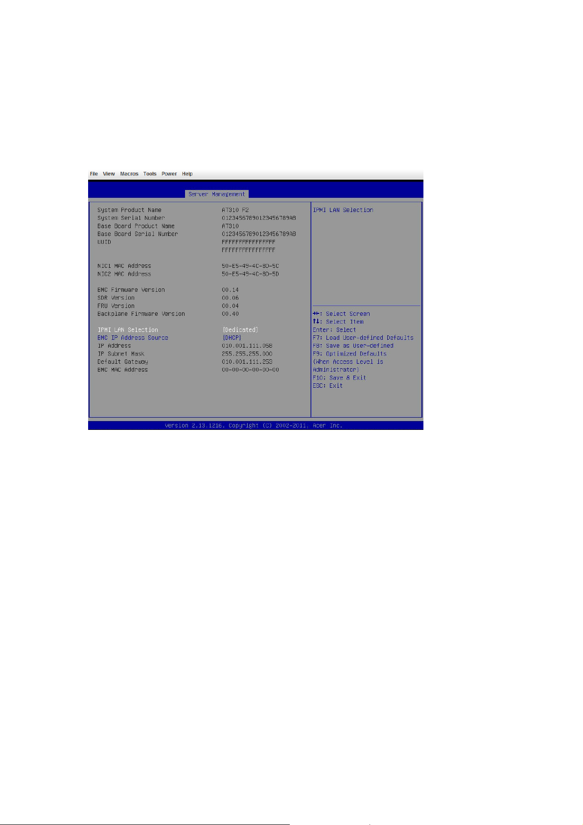
Console Redirection Configuration
Please follow the instruction to enable the console redirection function.
1. Go to BIOS setup menu.
2. Select Server Management.
3. Define IPMI LAN Selection and BMC IP Address Source.
4. Save the configuration and exit BIOS setup menu.
NOTE! If set to Shared mode, connect network cable to LAN2 port; if set to Fail-Over mode,
connect network cable to LAN 2 or LANM port.
5
Page 7
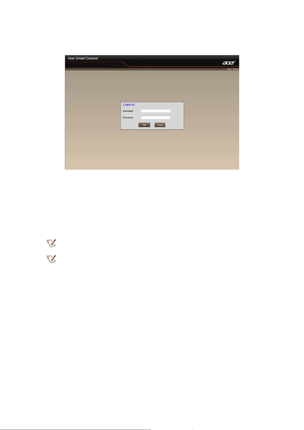
Acer Smart Console Overview
1. Open a web browser and type in your identified IP. The IP address can be found using your
DHCP server.
2. A dialog box prompts you to enter Username and Password.
3. Enter the following values:
Username: root
Password: superuser
The default user name and password are in lower-case characters.
When you log in using the root user name and password, you have full administrative
powers. It is advised that once you log in, you change the root password.
6
Page 8
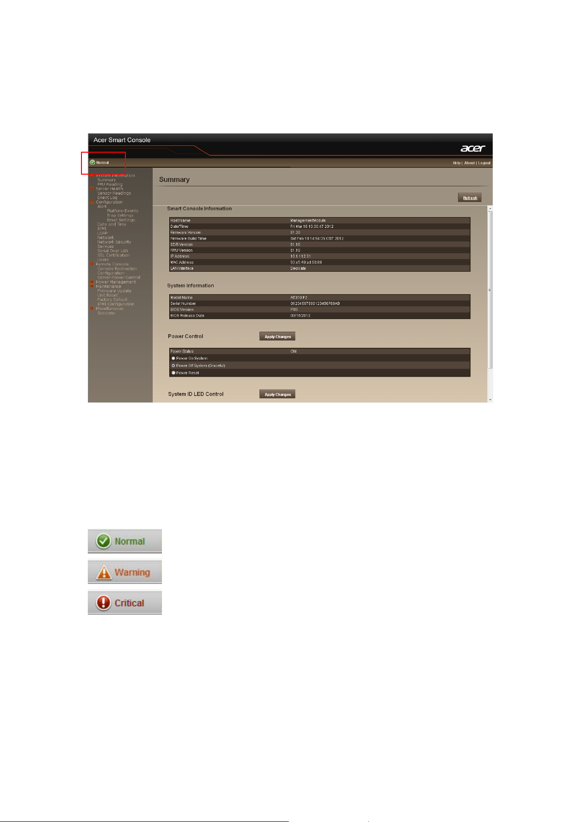
Enter Acer Smart Console
After you successfully log into your Acer Smart Console, the Remote Management Console GUI
appears.
Smart Console Information
Smart Console Information shows the general system health status of the current remote client. It
contains three main system health status: Smart Console Information, System Information, Power
Control and System ID LED Control.
The System Status will appear on the left upper corner with different color, each color definition
will be described in the following:
Normal: All sensors are normal and there’s no sensor that has any alert.
Warning: There’s at least one sensor that has warning alert.
Critical: There’s at least one sensor that has critical alert.
Priority: Critical > Warning > Normal
7
Page 9
System Information
System Information contains two major system information: Summary, and FRU Reading.
Summary displays the general system information and FRU reading shows the major system
component FRU information.
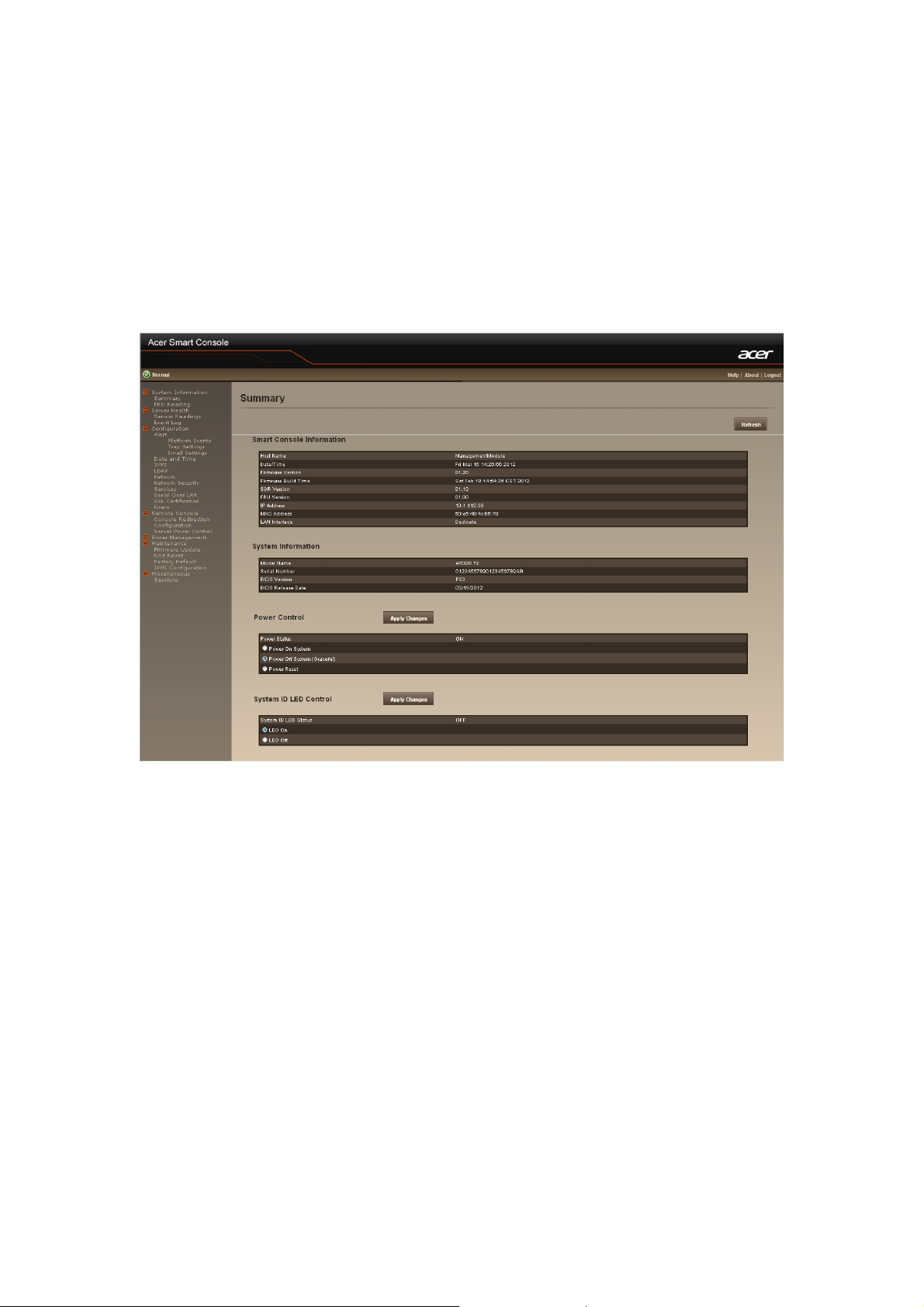
Summary
Summary displays the Smart Console Information and System Information of current remote
client system; it also provides options for Power Control and System ID LED Control of current
remote client system.
Power Control
The Power Control allows you to power on/off/reset the remote host system. Additionally you can
see the remote power status.
To perform the power control operation, select the operation and click “Apply Changes”.
System ID LED Control
The System ID LED Control allows you to define system ID LED on/off of the remote host
system. Additionally you can see the remote system ID LED status.
To perform the system ID LED control operation, select the operation and click “Apply Changes”.
To refresh the system information, just click “Refresh”
8
Page 10
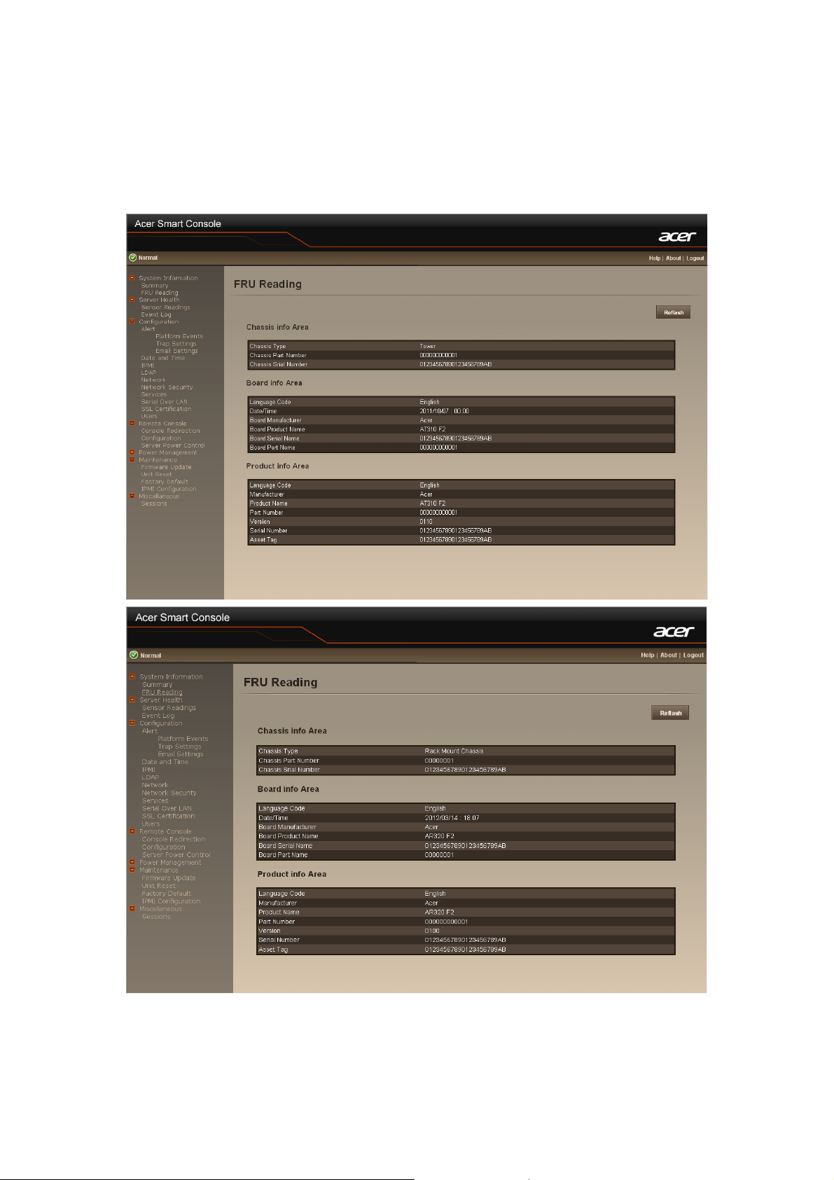
FRU Reading
User also can get the FRU information by selecting FRU Reading from the function list of left
window.
After selecting FRU Reading, it shows all FRU information. FRU information includes: Chassis
information, Board information, and Product information.
9
Page 11
Server Health
This section shows you data related to the sensor’s health, such as sensor reading.
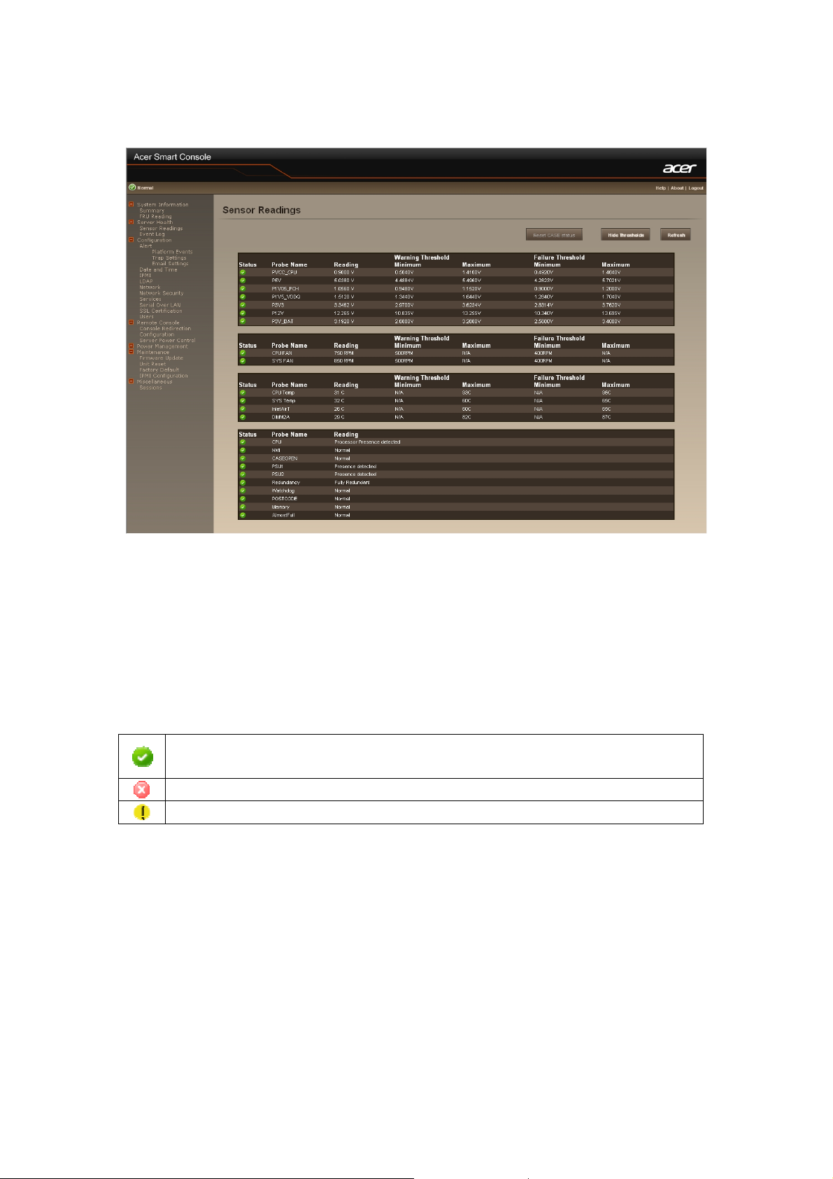
Sensor Readings
It reads all the sensor information of system. It lists the System’s Voltage, System /CPU FAN, and
CPU/System Temperature senor information. You can select single sensor information from the
drop-down list.
Sensor Display Icon
On each sensor displays different color icon. The color icon indicates the health status of specified
device.
Indicates the device is health.
Indicates the device has warning alert.
Means the device has critical alert.
Reset Case Status
When the chassis case is opened, the BMC will raise case intrusion alters. Check the chassis case
is closed properly and press the “Reset Case Status” to reset the case status.
Hide Threshold
You can click “Hide Thresholds” to hide the thresholds of every sensor.
To refresh the sensor status, just click “Refresh”.
10
Page 12
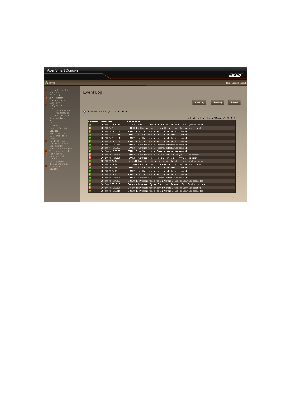
Event Log
It records the event when sensor has abnormal state. When the log matches the pre-defined alert,
the system will send out the notification automatically if it is pre-configured.
To clear the event lot, just click “Clear Log”.
To save the event lot, just click “Save Log”.
To refresh the event log, just click “Refresh”.
11
Page 13

Configuration
Alert
Alter contains three major alter configuration: Platform Event, Trap Settings, and Email Settings.
Platform Event
A platform event filter (PEF) can trigger an action and generate an alert when a critical
hardware-related event occurs. For each PEF, you can choose the action to be taken when a
platform event occurs.
You can also choose to generate and send an alert when a platform event occurs. In the Platform
Events screen, you can enable the generation of platform event alerts globally by clicking Global
Alerting Enable.
When you finish the configuration, click “Apply Changes”.
12
Page 14

T rap Settings
In the Trap Settings, user can set the IPv4 and Ipv6 Destination List.
IPv6 and IPv4 are two completely separate protocols. IPv6 is not backwards compatible with IPv4,
and IPv4 hosts and routers will not be able to deal directly with IPv6 traffic.
IPv6 has a significantly larger address space than IPv4. This results from the use of a 128-bit
address, whereas IPv4 uses only 32 bits.
When you finish the configuration, click “Apply Changes”.
13
Page 15

Email Settings
If you want the alert to be sent by email, you can configure to specify the e-mail address, subject
and message in the Email Settings. After you finish the configuration, click Apply Change to save
the settings.
SMTP
Set E-mail (SMTP) server IP address for sending alert notification to user.
Check the SMTP Authentication Enabled box and enter the SMTP IP address, User Name,
Password; select the STARTTLS Mode and SASL Mode from the drop-down list.
When you finish the configuration, click “Apply Changes”.
14
Page 16

Date and Time
This page provides the mechanism to configure the Network Time acquisition method. With
Administrator or Operator privilege level, you can modify configuration settings and click the
Apply Changes button to execute the settings, as well as click the Sync Time Now button (when in
Requested Mode) to request an immediate clock set.
Operation Mode
Configures the NTP Mode. You can Disable NTP, set Requested Mode, or Daemon Mod e in this
parameter.
In Requested Mode, you can request an immediate clock synchronization with the NTP server;
request will be sent when click the Sync Time Now button.
The Daemon Mode runs NTP daemon which sends a NTP request at approximately 5 minute
intervals. Multiple NTP servers may be specified to provide redundancy.
Time Synchronization Method
Specifies the synchronization method for Requested Mode. Select Slew mode when you want to
adjust the time smoothly over time if there are time sensitive applications in place. Select Step
mode to aggressively change the time using settimeofday() system call.
15
Page 17

IPMI
This screen contains two sections: IPMI Serial and IPMI Settings.
IPMI Serial
There are four serial configuration in IPMI Serial: Connection Mode Settings, Baud Rate, Flow
Control, and Channel Privilege Level Limit.
The Connection Mode Settings allows user to select the Console redirection type and to manage
the system from a remote location.
Once the connection mode is set, select the Baud Rate and Flow Control from the drop-down list.
With Channel Privilege Level Limit, users can be configured to operate with a particular
maximum Privilege Level. Privilege levels tell the BMC which commands are allowed to be
executed. The following table shows the Channel Privilege Level.
Users This may be considered the lowest privilege level.
Operator All BMC commands are allowed, except for configuration
commands that can change the behavior of the out-of-band
interfaces. For example, Operator privilege does not allow the
capability to disable individual channels, or change user
access privileges.
Administrator All BMC commands are allowed, including configuration
commands. An Administrator can even execute configuration
commands that would disable the channel that the
Administrator is communicating over.
16
Page 18

IPMI Settings
IPMI Settings provides remote configuration over LAN. To activate IPMI remote configuration by
LAN, check Enable IPMI Over LAN option, define the Channel Privilege Level Limit, and enter
the Encryption Key.
When you finish the configuration, click “Apply Changes”.
17
Page 19

LDAP
LDAP screen allows download user list of LDAP server then create Acer Smart Console user
account from this list directly.
Check the box below to enable LDAP authentication and enter the required information to access
the LDAP server. Click “Apply Changes” to save your changes.
18
Page 20

Network
You can view and modify the network settings on this screen. Select the Network Mode from the
drop-down list.
Dedicate Mode
When set to Dedicate Mode, you can configure the BMC related settings through the BMC port.
Shared Mode
When set to Shared Mode, you can configure the BMC related settings through the NIC2 port.
(Shared NIC Mode)
Failover Mode
When set to Failover Mode, you can configure the BMC related settings through the BMC or
NIC2 port. (Backup Mode)
When you finish configuration, click “Apply Change”.
Please note that the changes may not take effect immediately, click "Refresh" to take effect of
changes.
19
Page 21

Device Connection Sequence
Mode 1.
LANM
Dedicated
Shared
Fail-Over
V
V
V V LANM or LAN2
2.
LAN2
3.
Remark
LAN1
20
Page 22

Network Security
You can configure the network security settings on this screen. Check the IP Blocking Enabled
box and input the desire value of IP Blocking Fail Count, IP Blocking Fail Window, and IP
Blocking Penalty Time. After you finish the configuration, click “Apply Change” to save the
settings.
21
Page 23

Services
You can configure the web server parameters (such as, HTTP Port Number, HTTPS Port Number,
and Timeout) on a remote computer. By default, the timeout is 1800 seconds.
When you finish the configuration, click “ Apply Changes”.
22
Page 24

Serial Over LAN
You can configure the Serial Over LAN settings on this screen. Check the Enable Serial Over
LAN box and select the Baud Rate and Channel Privilege Limit from the drop-down list. After
you finish the configuration, click “Apply Change” to save the settings.
23
Page 25

SSL Certification
SSL Certification shows the current certificate status. To generate a new certificate, click
“Generate Certificate”.
To upload a certificate, click “Upload Certificate”.
24
Page 26

Users
To configure a specific user, click the Users ID. When you finish the configuration, click “ Apply
Changes”.
To display new user information, click “Refresh”.
25
Page 27

Remote Console
Console Redirection
This screen allows you to start a Remote Console session with the host system.
Click Launch Java KVM Client to launch the redirection console and manage the server
remotely. After clicking the button, a console appears as below:
For KVM and remote redirection detail function description, please go to chapter:
KVM Function Description
26
Page 28

Click Launch Java VM Client to launch the redirection console and manage the local computer.
After clicking the button, a console appears as below:
Function Item Resulting Action
Mapped Check the mapped box next to the drive types you want to
connect.
Create Image…
Add Image…
Remove Image
Click the Create Image…button and create to the image.
Click the Add Image…button and browse to the image.
Click the Remove Image…button and remove to the
image.
Exit
Click Exit button to terminate the Media Redirection
wizard.
Details
Click Details to see more information of the image.
27
Page 29

Console Redirection Configuration
This screen allows you to configure the Remote Console settings. Check the Virtual KVM
Configuration Enabled box or Virtual Media Configuration Enabled box, and select the Max
Sessions, Remote Port, Video Encryption Enabled, and Preference Client from the drop-down
list. After you finish the configuration, click “Apply Change” to save the settings.
28
Page 30

Server Power Control
The Server Power Control allows you to power on/off/cycle the remote host system. Additionally
you can see the remote power status.
To perform the power control operation, select the operation and click “Apply Changes”.
29
Page 31

Power Management (Optional)
This screen displays information on the system power consumption and configuration of system
power consumption. The system power consumption information includes Current Power
Consumption, Max Power Consumption, Min Power Consumption, and Average Power
Consumption.
With the configuration of system power consumption, check the Power Limit Management
Activated Enabled box, and configure all related settings in the Power Limit.
When you finish the configuration, click “Apply Changes”.
Please note that the Power Management screen appears only when the PMBUS connector is
configured.
30
Page 32

Maintenance
Firmware Updates
The firmware can be updated remotely .
To update firmware, follow the instruction be low:
1. Select Update Type.
2. Select the file on your local system using Browse.
3. Click Upload to update to the new version of firmware.
31
Page 33

Unit Reset
Unit Reset provides BMC reboot function. To reboot system, click Reboot.
Factory Default
Factory Default provides BMC Factory default restore function.
To restore factory default, click Factory Default.
32
Page 34

IPMI Configuration
You can use this page to backup and restore the previous configuration that made in the Acer
Smart Console.
1. Click Backup to download the backup file
2. Select the file on your local system using Browse.
3. Click Restore to restore your configuration.
33
Page 35

Miscellaneous
Sessions
This screen displays information on Active Sessions. Additionally, the trash can icon provides the
delete function for privileged users. Click Refresh to refresh the Sessions status.
34
Page 36

KVM Function Description
After selecting KVM Remote Console Redirection button, system will lead you to the main
menu of KVM window which is shown as below:
Main Menu
The items in the main menu will be described in the following sections..
File
Menu Item Resulting Action
File→Capture to File
File→Exit
Save s a snapshot of the target’s desktop to a file.
Terminate the KVM session and close.
35
Page 37

View
Menu Item Resulting Action
View → Hide/Show Status Bar
View →Refresh
View →Full Screen
View →Fit
Hide / Show the status bar which includes "Session IP
address", "Session Username", "Frame Rate", and
“Bandwidth".
Sends a request to the KVM server asking for a reference
screen.
Will switch to full screen mode. This menu is only available
when not in full screen mode.
Resized the window to the size needed to completely
display the targets desktop without an extra border or
scrollbars. This will only work if the client desktop is large
enough to accommodate the resized window.
36
Page 38

Marcos
Macros are a mechanism to send keystrokes to the target that the user may otherwise not be able to
send. One of the most obvious examples of this is the Ctrl-Alt-Del sequence under Window.
Because this sequence of keystrokes is intercepted by the Windows OS, the KVM client will never
receive the complete sequence and can therefore never send them to the target through normal
keyboard operation. The solution to this is to provide an alternate mechanism for generate these
keystrokes. We refer to these keystroke sequences as macros.
The list of supported macros is as follows:
Tools
Menu Item Resulting Action
Tools → Session Options
Tools → Session User List
Tools → Single Cursor
Tools → Stats
This will bring up the session options dialog.
This will display all shared KVM users name.
Causes the viewer to enter single cursor mode.
Will display the perform ance statistics dialog.
37
Page 39

Power
Menu Item Resulting Action
Power → Power On System
Power → Power Off System
Power → Graceful Shutdown
Power → Reset System (warm
boot)
Power → Power Cycle System
(cold boot)
Help
Turns the power on.
Turns the power off.
Issue a graceful shutdown command to the target.
Issues a reboot command to the target. Target will reboot
without powering off.
This will power cycle the target by tur ni n g the power off for
a short period of time and then back on again.
Menu Item Resulting Action
Help → Contents and Index
Help → About
Will cause the viewer help to be displayed.
Will display a dialog with the product name, version, and
copyright notices.
38
 Loading...