

Page 1

AR320 F1 Series
User Guide
Page 2

© 2010. All Rights Reserved.
Acer AR320 F1 Series
User Guide
Acer AR320 F1
Model Number :
Serial Number:
Purchase Date:
Place of Purchase:
Page 3

iii
Information for your safety and comfort
Safety instructions
Read these instructions carefully. Keep this document for future reference.
Follow all warnings and instructions marked on the product.
Turning the product off before cleaning
Unplug this product from the wall outlet before cleaning. Do not use liquid
cleaners or aerosol cleaners. Use a damp cloth for cleaning.
CAUTION for power cord
Observe the following guidelines when connecting and disconnecting power to
the power supply unit:
• Install the power supply unit before connecting the power cord to the AC
power outlet.
• Unplug the power cord before removing the power supply unit from the
computer.
• If the system has multiple sources of power, disconnect power from the
system by unplugging all power cords from the power supplies.
CAUTION for accessibility
Be sure that the power outlet you plug the power cord into is easily accessible
and located as close to the equipment operator as possible. When you need to
disconnect power to the equipment, be sure to unplug the power cord from the
electrical outlet.
Warnings
• Restricted access location: location for equipment where both of the
following apply:
• access can only be gained by service persons or users who have been
instructed about the reasons for the restrictions applied to the
location and about any precautions that shall be taken; and
• access is through the use of a tool or lock and key, or other means of
security, and is controlled by the authority responsible for the
location.
• Do not use this product near water.
• Do not place this product on an unstable cart, stand or table. If the product
falls, it could be seriously damaged.
Page 4

iv
• Slots and openings are provided for ventilation to ensure reliable
operation of the product and to protect it from overheating. These
openings must not be blocked or covered. The openings should never be
blocked by placing the product on a bed, sofa, rug or other similar surface.
This product should never be placed near or over a radiator or heat
register, or in a built-in installation unless proper ventilation is provided.
• Never push objects of any kind into this product through cabinet slots as
they may touch dangerous voltage points or short-out parts that could
result in a fire or electric shock. Never spill liquid of any kind onto or into
the product.
• To avoid damage of internal components and to prevent battery leakage,
do not place the product on a vibrating surface.
• Never use it under sporting, exercising, or any vibrating environment
which will probably cause unexpected short current or damage rotor
devices, HDD, Optical drive, and even exposure risk from lithium battery
pack.
Using electrical power
• This product should be operated from the type of power indicated on the
marking label. If you are not sure of the type of power available, consult
your dealer or local power company.
• Do not allow anything to rest on the power cord. Do not locate this
product where people will walk on the cord.
• If an extension cord is used with this product, make sure that the total
ampere rating of the equipment plugged into the extension cord does not
exceed the extension cord ampere rating. Also, make sure that the total
rating of all products plugged into the wall outlet does not exceed the fuse
rating.
• Do not overload a power outlet, strip or receptacle by plugging in too
many devices. The overall system load must not exceed 80% of the branch
circuit rating. If power strips are used, the load should not exceed 80% of
the power strip's input rating.
• This product's power supply is equipped with a three-wire grounded plug.
The plug only fits in a grounded power outlet. Make sure the power outlet
is properly grounded before inserting the power supply plug. Do not insert
the plug into a non-grounded power outlet. Contact your electrician for
details.
Warning! The grounding pin is a safety feature. Using a power outlet that is
not properly grounded may result in electric shock and/or injury.
Page 5

v
Note: The grounding pin also provides good protection from unexpected
noise produced by other nearby electrical devices that may interfere with
the performance of this product.
• Use the product only with the supplied power supply cord set. If you need
to replace the power cord set, make sure that the new power cord meets
the following requirements: detachable type, UL listed/CSA certified, VDE
approved or its equivalent, 4.6 meters (15 feet) maximum length.
Product servicing
Do not attempt to service this product yourself, as opening or removing covers
may expose you to dangerous voltage points or other risks. Refer all servicing to
qualified service personnel.
Unplug this product from the wall outlet and refer servicing to qualified service
personnel when:
• The power cord or plug is damaged, cut or frayed.
• Liquid was spilled into the product.
• The product was exposed to rain or water.
• The product has been dropped or the case has been damaged.
• The product exhibits a distinct change in performance, indicating a need
for service.
• The product does not operate normally after following the operating
instructions.
Note: Adjust only those controls that are covered by the operating
instructions, since improper adjustment of other controls may result in
damage and will often require extensive work by a qualified technician to
restore the product to normal condition.
CAUTION: Danger of explosion if battery is incorrectly replaced. Replace only
with the same or equivalent type recommended by the manufacturer. Dispose
of used batteries according to the manufacturer’s instructions.
Page 6
vi
Additional safety information
Your device and its enhancements may contain small parts. Keep them out of
the reach of small children.
Disposal instructions
Do not throw this electronic device into the trash when
discarding. To minimize pollution and ensure utmost protection
of the global environment, please recycle. For more
information on the Waste from Electrical and Electronics
Equipment (WEEE) regulations, visit
www.acer-group.com/public/Sustainability/sustainability01.htm.
Mercury advisory
For projectors or electronic products containing an LCD/CRT
monitor or display: Lamp(s) inside this product contain mercury and
must be recycled or disposed of according to local, state or federal
laws. For more information, contact the Electronic Industries Alliance at
www.eiae.org. For lamp-specific disposal information, check
www.lamprecycle.org.
Tips and information for comfortable use
Computer users may complain of eyestrain and headaches after prolonged use.
Users are also at risk of physical injury after long hours of working in front of a
computer. Long work periods, bad posture, poor work habits, stress,
inadequate working conditions, personal health and other factors greatly
increase the risk of physical injury.
Incorrect computer usage may lead to carpal tunnel syndrome, tendonitis,
tenosynovitis or other musculoskeletal disorders. The following symptoms may
appear in the hands, wrists, arms, shoulders, neck or back:
• numbness, or a burning or tingling sensation
• aching, soreness or tenderness
• pain, swelling or throbbing
• stiffness or tightness
• coldness or weakness
If you have these symptoms, or any other recurring or persistent discomfort
and/or pain related to computer use, consult a physician immediately and
inform your company's health and safety department.
The following section provides tips for more comfortable computer use.
Page 7

vii
Finding your comfort zone
Find your comfort zone by adjusting the viewing angle of the monitor, using a
footrest, or raising your sitting height to achieve maximum comfort. Observe
the following tips:
• Refrain from staying too long in one fixed posture.
• Avoid slouching forward and/or leaning backward.
• Stand up and walk around regularly to remove the strain on your leg
muscles.
• Take short rests to relax your neck and shoulders.
• Avoid tensing your muscles or shrugging your shoulders.
• Install the external display, keyboard and mouse properly and within
comfortable reach.
• If you view your monitor more than your documents, place the display at
the center of your desk to minimize neck strain.
Taking care of your vision
Long viewing hours, wearing incorrect glasses or contact lenses, glare, excessive
room lighting, poorly focused screens, very small typefaces and low-contrast
displays could stress your eyes. The following sections provide suggestions on
how to reduce eyestrain.
Eyes
• Rest your eyes frequently.
• Give your eyes regular breaks by looking away from the monitor and
focusing on a distant point.
• Blink frequently to keep your eyes from drying out.
Display
• Keep your display clean.
• Keep your head at a higher level than the top edge of the display so your
eyes point downward when looking at the middle of the display.
• Adjust the display brightness and/or contrast to a comfortable level for
enhanced text readability and graphics clarity.
• Eliminate glare and reflections by:
• Placing your display in such a way that the side faces the window or
any light source.
• Minimizing room light by using drapes, shades or blinds.
• Using a task light.
• Changing the display's viewing angle.
Page 8

viii
• Using a glare-reduction filter.
• Using a display visor, such as a piece of cardboard extended from the
display's top front edge.
• Avoid adjusting your display to an awkward viewing angle.
• Avoid looking at bright light sources, such as open windows, for extended
periods of time.
Developing good work habits
Develop the following work habits to make your computer use more relaxing
and productive:
• Take short breaks regularly and often.
• Perform some stretching exercises.
• Breathe fresh air as often as possible.
• Exercise regularly and maintain a healthy body.
Page 9

ix
Regulations and safety notices
FCC notice
This device has been tested and found to comply with the limits for a Class A
digital device pursuant to Part 15 of the FCC rules. These limits are designed to
provide reasonable protection against harmful interference in a residential
installation. This device generates, uses, and can radiate radio frequency energy
and, if not installed and used in accordance with the instructions, may cause
harmful interference to radio communications.
However, there is no guarantee that interference will not occur in a particular
installation. If this device does cause harmful interference to radio or television
reception, which can be determined by turning the device off and on, the user
is encouraged to try to correct the interference by one or more of the following
measures:
• Reorient or relocate the receiving antenna.
• Increase the separation between the device and receiver.
• Connect the device into an outlet on a circuit different from that to which
the receiver is connected.
• Consult the dealer or an experienced radio/television technician for help.
Notice: Shielded cables
All connections to other computing devices must be made using shielded cables
to maintain compliance with FCC regulations. In compliance with FCC
regulations, use shielded cables to connect to other computing devices. A duallink cable is recommended for DVI output.
Notice: Peripheral devices
Only peripherals (input/output devices, terminals, printers, etc.) certified to
comply with the Class A limits may be attached to this equipment. Operation
with non-certified peripherals is likely to result in interference to radio and TV
reception.
Caution
Changes or modifications not expressly approved by the manufacturer could
void the user's authority, which is granted by the Federal Communications
Commission, to operate this computer.
Page 10

x
Operation conditions
This device complies with Part 15 of the FCC Rules. Operation is subject to the
following two conditions: (1) this device may not cause harmful interference,
and (2) this device must accept any interference received, including interference
that may cause undesired operation.
Notice: Canadian users
This Class A digital apparatus complies with Canadian ICES-003.
Remarque à l'intention des utilisateurs canadiens
Cet appareil numérique de la classe B est conforme a la norme NMB-003 du
Canada.
Compliant with Russian regulatory certification
Notice for Australia
For safety reasons, only connect headsets with a
telecommunications compliance label. This includes customer equipment
previously labelled permitted or certified.
Notice for New Zealand
1 The grant of a Telepermit for any item of terminal equipment indicates
only that Telecom has accepted that the item complies with minimum
conditions for connection to its network. It indicates no endorsement of
the product by Telecom, nor does it provide any sort of warranty. Above
all, it provides no assurance that any item will work correctly in all respects
with another item of Telepermitted equipment of a different make or
model, nor does it imply that any product is compatible with all of
Telecom's network services.
2 This equipment is not capable, under all operating conditions, of correct
operation at the higher speeds for which it is designed. Telecom will accept
no responsibility should difficulties arise in such circumstances.
3 Some parameters required for compliance with Telecom's Telepermit
requirements are dependent on the equipment (PC) associated with this
device. The associated equipment shall be set to operate within the
following limits for compliance with Telecom's Specifications:
a There shall be no more than 10 call attempts to the same number
within any 30 minute period for any single manual call initiation, and
b The equipment shall go on-hook for a period of not less than 30
seconds between the end of one attempt and the beginning of the
next call attempt.
Page 11

xi
4 Some parameters required for compliance with Telecom's Telepermit
requirements are dependent on the equipment (PC) associated with this
device. In order to operate within the limits for compliance with Telecom's
specifications, the associated equipment shall be set to ensure that
automatic calls to different numbers are spaced such that there is not less
than 5 seconds between the end of one call attempt and the beginning
of another.
5 This equipment shall not be set up to make automatic calls to Telecom's
111 Emergency Service.
6 This device is equipped with pulse dialing while the Telecom standard is
DTMF tone dialing. There is no guarantee that Telecom lines will always
continue to support pulse dialing.
7 Use of pulse dialing, when this equipment is connected to the same line as
other equipment, may give rise to bell tinkle or noise and may also cause a
false answer condition. Should such problems occur, the user should NOT
contact the telecom Fault Service.
8 This equipment may not provide for the effective hand-over of a call to
another device connected to the same line.
9 Under power failure conditions this appliance may not operate. Please
ensure that a separate telephone, not dependent on local power, is
available for emergency use.
Notice: BSMI
Laser compliance statement
The CD or DVD drive used with this computer is a laser product.
The CD or DVD drive's classification label (shown below) is located on the drive.
CLASS 1 LASER PRODUCT
CAUTION: INVISIBLE LASER RADIATION WHEN OPEN. AVOID EXPOSURE
TO BEAM.
Appareil à laser de classe 1
Attention : Radiation laser visible et invisible en cas d’ouverture. Éviter toute
exposition aux rayons.
Laserprodukt der Klasse 1
Achtung: Beim Öffnen werden unsichtbare Laserstrahlen freigelegt. Setzen Sie
sich diesen Strahlen nicht aus.
Page 12

xii
Prodotto laser di classe 1
Attenzione: Radiazioni laser invisibili in caso d’apertura. Evitare l’esposizione ai
raggi.
Producto l
Precauci
haz de luz.
Produto Laser de Classe 1
Precaução: Radiação laser invisível quando aberto. Evite exposição ao feixe.
Laserproduct klasse 1
Voorzichtig: Onzichtbare laserstraling indien geopend. Voorkom blootstelling
aan straal.
áser de Clase 1
ón: Cuando está abierta, hay radiación láser. Evite una exposición al
Digital audio output statement
The optical connector contains no laser or light emitting diode (LED) more than
Class I.
Radio device regulatory notice
Note: Below regulatory information is for models with wireless LAN and/or
Bluetooth only.
General
This product complies with the radio frequency and safety standards of any
country or region in which it has been approved for wireless use. Depending on
configurations, this product may or may not contain wireless radio devices (such
as wireless LAN and/or Bluetooth modules).
Declaration of Conformity for EU countries
Hereby, Acer, declares that this system is in compliance with the essential
requirements and other relevant provisions of Directive 1999/5/EC.
List of applicable countries
This device must be used in strict accordance with the regulations and
constraints in the country of use. For further information, please contact local
office in the country of use. Please see http://ec.europa.eu/enterprise/rtte/
implem.htm for the latest country list.
Page 13

xiii
ENEGY STAR
ENERGY STAR qualified products save you money by reducing
energy cost and protecting the environment without sacrificing
features or performance. Acer is proud to offer our customers
products with the ENERGY STAR mark.
What is ENERGY STAR?
Products that are ENERGY STAR qualified use less energy and prevent
greenhouse gas emissions by meeting strict energy efficient guidelines set by
the U.S. Environmental Protection Agency. Acer is committed to offer products
and services worldwide that help customers save money, conserve energy and
improve the quality of our environment. The more energy we can save through
higher energy efficiency, the more we reduce greenhouse gases and the risks of
climate change. For more information, go to www.energystar.gov or
www.energystar.gov/powermanagement.
Note: The statement above is applicable only to Acer system with an
ENERGY STAR sticker.
Page 14

xiv
Page 15

Information for your safety and comfort iii
Regulations and safety notices ix
1 System tour 1
System notes 2
External and internal structure 3
Front panel 3
Rear panel 5
Internal components 7
Mainboard 8
2 System setup 13
Setting up the system 14
Pre-installation requirements 14
Connecting peripherals 15
Front connections 15
Rear connections 15
Turning on the system 16
Power-on problems 17
Configuring the system OS 18
Turning off the system 19
3 System upgrades 21
Installation precautions 22
ESD precautions 22
Pre-installation instructions 22
Post-installation instructions 23
Configuring the storage devices 24
Accessing the drive bays 24
Guidelines for configuring hard disk drives 24
Determining the drive status 25
Removing and installing a hard disk drive 25
Installing an additional hard disk drive with carrier 26
Opening the server 29
Removing and installing an optical drive 30
Removing and installing the air duct 31
Replacing a system fan 33
Replacing the processor and heatsink 34
Removing the heatsink 35
Installing a heatsink 36
Upgrading the processor 37
Contents
Page 16

xvi
Upgrading the system memory 41
Installing an expansion card 46
Installing a PCI Express card on the left slot 46
Installing a PCI Express card on the right slot 49
4 System BIOS 53
BIOS overview 54
Entering BIOS Setup 55
BIOS setup primary menus 55
BIOS setup navigation keys 56
Main menu 57
Advanced menu 59
Processor Configuration 60
Memory Configuration 64
ATA Controller Configuration 65
Serial Port Configuration 68
PCI Configuration 69
Advanced Chipset Configuration 70
System Acoustic & Performance Configuration 72
Power menu 74
Security menu 76
Setting a system password 78
Changing a system password 78
Removing a system password 78
Server Management menu 79
System Information 80
Console Redirection 81
Event Log Configuration 82
Boot menu 84
Exit menu 85
5 System troubleshooting 87
Resetting the system 88
Initial system startup problems 88
BIOS error beep codes 89
Initial troubleshooting checklist 90
Hardware diagnostic testing 91
Checking the boot-up status 91
Verifying the condition of the storage devices 92
Confirming loading of the operating system 92
Specific problems and corrective actions 93
Page 17

Appendix A Server management tools 99
Server management overview 100
RAID configuration utilities 101
MEGARAID SAS 8204ELP configuration 101
Onboard SATA RAID creation 103
Appendix B Rack mount configuration 105
Rack installation information 106
System rack installation 108
Vertical mounting hole pattern 109
Installing the system into the rack 110
Appendix C Acer Smart Console 115
Using Acer Smart Console 116
Software Installation 117
Prerequisites on remote management PC 117
Installing the Java Tool 117
Installing the UPnP tool 118
Using the UPnP tool to search for a server 119
Configuring the BMC NIC settings 121
Accessing Acer Smart Console 123
Acer Smart Console user interface 125
System status indicator 125
System Information 126
Server Health 128
Configuration 131
Remote Control 143
Maintenance 145
KVM Remote Console Utility 147
Menu bar 148
xvii
Index 151
Page 18

xviii
Page 19

1 System tour
Page 20

2
System notes
1 System tour
The AR320 is an entry-level 1U single processor server system based on
the Intel Foxhollow platform. This system integrated the new Intel
chip architecture solution for Intel
processors, and Intel
the 3420 (Ibex Peak) chipset, with DDR3 technology supporting both
Unbufferred ECC and Register DIMMs up to 1333 MHz in speed.
This server has two PCI-E IO connectors to support two low-profile PCIE
cards, onboard Intel SATA software RAID that supports RAID levels 0, 1,
5 and 10, onboard BMC, iKVM feature and integrated VGA with 32 MB
memory.
This server supports one slim type optical device and a maximum of
four hot-swappable 3.5-inch SATA/SAS hard disk drives.
The AR320 delivers affordable, reliable, manageable and optimized
performance for small businesses. It is ideal for single-application IT
infrastructure, web and edge-of-network applications.
®
Xeon® X3400 Series quad core processors and
i3 series and Pentium dual core
®
2-
Page 21

External and internal structure
Front panel
The illustration below shows the system front panel.
No. Icon Component No. Icon Component
1 USB 2.0 ports 8 System ID button
3
2 HDD activity
indicator
3 Power indicator 10 Optical drive bay
4 LAN1 activity
indicator
5 LAN2 activity
indicator
6 System ID indicator 13 3.5-inch hard disk
7 Status/fault
indicator
9 Power button
11 Hot-plug HDD activity
indicator
12 Hot-plug HDD status
indicator
drive (HDD) bays
14 Rack handles
Page 22

4
Front panel LED indicator status
LED indicator LED color LED state Status
Power
indicator
HDD activity
indicator
Green On S0: Power ON
Green Blink (1 Hz at
50% duty cycle)
N/A Off S4
N/A Off S5
Green Blink HDD Access
N/A Off No access and No HDD fault
S1: Sleep
1 System tour
System Status/
Fault indicator
LAN activity
indicators
(LAN1,
LAN2)
System ID
indicator
Green On System ready / no alarm
Green Blink (1 Hz at
50% duty cycle)
Amber On Critical alarm (critical failure
Amber Blink (1 Hz at
50% duty cycle)
N/A Off System not ready (Post error/
Green On LAN Link / No Access
Green Blink LAN Access
N/A Off Disconnect / Idle
N/A Off Normal
Blue On System ID button pressed
System ready but some CPU
functions and DIMM may be
degraded or damaged.
in power module, voltage,
power supply, temperature
and voltage, etc.)
Non-critical alarm (noncritical failures in
temperature, voltage, etc.)
NMI event/CPU or
terminator missing, etc.)
Page 23

Rear panel
No. Icon Component
1 Power supply module cord socket
2PS/2 mouse port
3 Serial port
4 Gigabit LAN ports (10/100/1000 Mbps)
5
5 Low-profile PCI Express 2.0 x8 expansion slots
6 System ID switch
7 Server management port (RJ-45) (10/100 Mbps)
8 USB 2.0 ports
9 Monitor port
10 PS/2 keyboard port
Page 24

6
Rear panel LED indicator status
LED indicator LED color LED state Status
1 System tour
System ID
indicator
N/A Off Normal
Blue On System ID button pressed
LAN port LED indicators
LED indicator LED color LED state Status
RJ-45 LED (Left) N/A Off No connection or 10 Mbps
Green On 100 Mbps
Amber On 1000 Mbps
RJ-45 LED (Right) Yellow On Active connection
Yellow Blinking Transmit/Receive activity
Page 25
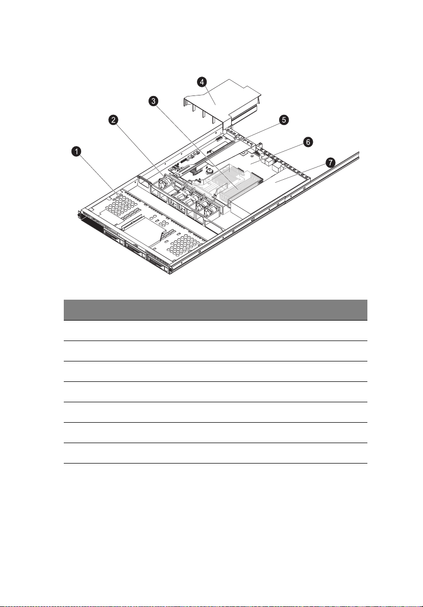
Internal components
No. Component
7
1 Hard disk drives
2 System fan modules
3 Memory modules
4 Air duct
5 PCI riser board bracket assembly
6 Mainboard
7 Power supply module
Page 26
8
1 System tour
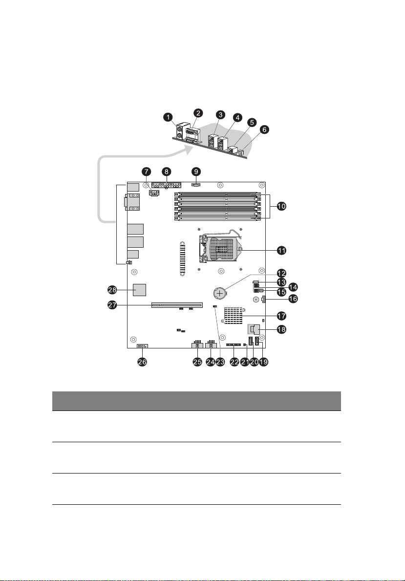
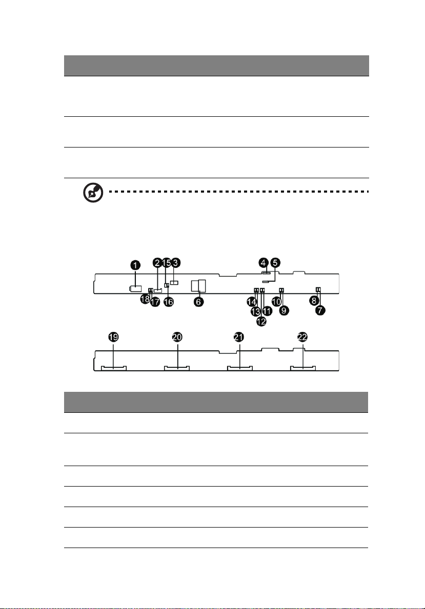
Mainboard
The mainboard becomes accessible once you open the system. It should
look like the figure shown below.
No. Code Description
1KB
MS
2COM1
VGA
3 GLAN1 LAN1 port (top)
PS/2 mouse port (top)
PS/2 keyboard port (bottom)
Serial port (top)
VGA port (bottom)
USB ports (bottom)
Page 27

No. Code Description
4 GLAN2 LAN2 port (top)
USB ports (bottom)
5 BMC_LAN Server management port
6 SW1 System ID button
7 ATX CPU 8-pin ATX power connector
8 ATX 24-pin ATX power connector
9 PWR_DET Power supply PSMI connector
9
10 DIMM 2A,
DIMM 2B,
DIMM 2C,
DIMM 1A,
DIMM 1B,
DIMM 1C
11 U1 Processor socket
12 BAT Battery
13 IPMB IPMB header (for an IPMI card)
14 Select jumpers
15 NMI_BTN NMI button
16 BPB_SMBUS Backplane board system management bus
17 U2 Intel 3420 PCH chipset
18 SATA0-3 Mini-SAS port (supports 4 ports, SATA only)
19 SATA4 SATA 4 port
20 SATA5 SATA 5 port
21 CASE_OPEN Chassis intrusion header
DDR3 DIMM slots
(SMBUS) connector
22 SB_PANEL Front control board cable connector
Page 28
10
No. Code Description
23 CLR_CMOS1 Clear CMOS jumper
24 USB1 Front USB1 cable connector
25 USB2 Internal USB connector
26 COM2 Connects to serial port
27 PCI3 PCI-E x16 slot
28 U28 BMC controller
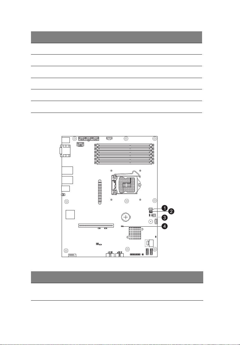
Mainboard jumper settings
1 System tour
Code Jumper
No.
BIOS_WP
1
BIOS data
write protect
Default Setting
1-2 Close: Normal (default setting)
2-3 Close: BIOS write protect
Page 29
Code Jumper
No.
11
Default Setting
2
3
4
PASSWORD
BIOS_RVCR
CLR_CMOS1
Set
Supervisor
Password
BIOS
recovery
Clear CMOS
1-2 Close: Set Supervisor Password
(default setting)
2-3 Close: Clear Supervisor Password
1-2 Close: Normal (default setting)
2-3 Close: Enable BIOS recovery
1-2 Close: Normal (default setting)
2-3 Close: Clear CMOS
Note: Jumpers not indicated are for test purposes only.
Backplane board and jumper settings
No.
1
2
3
4
5
6
Code Description
P2
J2
8-pin ATX power conector
SMBUS connector
Connects to mainboard or RAID card
CD-ROM_PW1
SGPIO_JP1
J12
SATA0-3
ODD power connector
SGPIO connector
MG9082 upgrade/debug header
Mini-SAS port (supports 4 ports)
Page 30

12
1 System tour
No.
7~18
19~22
Code Description
FAN_1A, FAN_1B,
FAN_2A, FAN_2B,
FAN_3A, FAN_3B,
FAN_4A, FAN_4B,
FAN_5A, FAN_5B,
FAN_6A, FAN_6B
SATA/SAS_3,
SATA/SAS_2,
SATA/SAS_1,
SATA/SAS_0
Fan connectors
SATA 0-3 connectors
Page 31

2 System
setup
Page 32

14
2 System setup
Setting up the system
Pre-installation requirements
Selecting a site
Before unpacking and installing the system, select a suitable site for
the system for maximum efficiency. Consider the following factors
when choosing a site for the system:
• Near a grounded power outlet.
• Clean and dust-free.
• Stable surface free from vibration.
• Well-ventilated and away from sources of heat.
• Protected from electromagnetic fields produced by electrical
devices such as air conditioners, radio and TV transmitters, etc.
Package contents
Ensure you have the following items:
• Acer AR320 system
• Acer AR320 accessory box
If any of the above items is damaged or missing, contact your dealer
immediately.
Save the boxes and packing materials for future use.
Page 33

Connecting peripherals
Caution! The server operates on 100 to 240 VAC only. Do not
connect the system to an incorrect voltage source.
Refer to the illustration below for specific connection instructions on
the peripherals you want to connect to the system.
Front connections
15
Rear connections
Note: Consult the operating system manual for information on
how to configure the network setup.
Page 34

16
2 System setup
Turning on the system
After making sure that you have properly set up the system and
connected all the required cables, you can now power on the system.
To power on the system:
After plugging in the power cord, press the power button.
The system starts up and displays a welcome message on the monitor.
After that, a series of POST messages appears. The POST messages
indicate if the system is running well or not.
Note: If the system does not turn on or boot after pressing the
power button(s), go to the next section for the possible causes of
the boot failure.
Aside from the POST messages, you can determine if the system is in
good condition by checking if the following occurred.
• The power indicator on the front panel lights up green.
• The Num Lock, Caps Lock, and Scroll Lock indicators on the
keyboard light up.
Page 35

Power-on problems
If the system does not boot after you have applied power, check the
following factors that might have caused the boot failure.
• The external power cord may be loosely connected.
Check the power cord connection from the power source to the
power supply module AC input connector on the rear panel. Make
sure that the power cord is properly connected to the power
source and to the AC input connector.
• No power comes from the grounded power outlet.
Have an electrician check your power outlet.
• Loose or improperly connected internal power cables.
Check the internal cable connections. If you are not confident to
perform this step, ask a qualified technician to assist you.
Warning! Make sure all power cords are disconnected from the
electrical outlet before performing this task.
Note: If you have gone through the preceding actions and the
system still fails to boot, ask your dealer or a qualified technician
for assistance.
17
Page 36
18
2 System setup
Configuring the system OS
Acer Smart Setup assists you to conveniently install your choice of
operating system.
Note: To purchase the Acer Smart Setup software, contact your
local Acer representative.
To start using Smart Setup, follow the steps below.
1 Locate the Smart Setup disc included in the system package.
2 If an optional optical drive is not installed in the server, connect an
external optical drive to your system. Press the Stop/Eject button
on the optical drive to eject the disc tray.
3 When the disc tray slides open, insert the Smart Setup disc with the
label or title side of the disc facing upward.
Note: When handling the disc, hold it by the edges to avoid
smudges or fingerprints.
4 Gently press the disc down to make sure that it is properly
inserted.
Caution! While pressing the disc, be careful not to bend the disc
tray. Make sure that the disc is properly inserted before closing
the disc tray. Improper insertion may damage both the disc and
the CD-ROM drive.
5 Gently press the drive Stop/Eject button again to close the disc
tray.
6 On the Acer Smart Setup window, select OS Installation.
7 Follow all onscreen instructions.
For more information, refer to the Smart Setup Help file.
Note: Acer Smart Setup only supports the Microsoft Windows
Server, Red Hat Enterprise Linux and SUSE Linux Enterprise Server
operating systems, The Windows or Red Hat installation disc(s) is
required to install the OS.
Page 37

19
Turning off the system
There are two ways to turn off the server — via software or via
hardware. The software procedure below applies to a system running
the Windows operating system. For further operating system
shutdown procedures, refer to the related user documentation.
To turn off the system via software:
1 Press <Ctrl> + <Alt> + <Delete> on the attached keyboard or click
Start on the Windows taskbar.
2 Select Shut Down.
3 Select Shut down from the drop-down window then click on OK.
To turn off the system via hardware:
If you cannot shut down the server using the software, press and hold
the power button for at least four seconds. Quickly pressing the button
may put the server in a Suspend mode only.
Page 38

20
2 System setup
Page 39

3 System
upgrades
Page 40

22
3 System upgrades
Installation precautions
Before you install any server component, we recommend that you read
the following sections. These sections contain important ESD
precautions along with pre-installation and post-installation
instructions.
ESD precautions
Electrostatic discharge (ESD) can damage the processor, disk drives,
expansion boards, mainboard, memory modules and other server
components. Always observe the following precautions before you
install a server component:
• Do not remove a component from its protective packaging until
you are ready to install it.
• Do not touch the component pins, leads, or circuitry.
• Components with a Printed Circuit Board (PCB) assembly should
always be laid with the assembly-side down.
• Wear a wrist grounding strap and attach it to a metal part of the
server before handling components. If a wrist strap is not
available, maintain contact with the server throughout any
procedure requiring ESD protection.
• Keep the work area free of nonconductive materials, such as
ordinary plastic assembly aids and foam packing.
Pre-installation instructions
Perform the steps below before you open the server or before you
remove or replace any component:
Warning! Failure to properly turn off the server before you start
installing components may cause serious damage. Do not attempt
the procedures described in the following sections unless you are
a qualified service technician.
1 Turn off the system and all the peripherals connected to it.
2 Unplug all cables from the power outlets.
3 Disconnect all telecommunication cables from their ports.
Page 41

4 Place the system unit on a flat, stable surface.
5 Open the system according to the instructions on page 29.
6 Follow the ESD precautions described in this section when
handling a server component.
Post-installation instructions
Perform the steps below after installing a server component.
1 See to it that all components are installed according to the
described step-by-step instructions.
2 Reinstall all components or cable that have been previously
removed.
3 Reinstall the top cover.
4 Reconnect the necessary cables.
5 Turn on the system.
23
Page 42

24
3 System upgrades
Configuring the storage devices
The system supports up to four 3.5-inch hot-plug SATA/SAS hard disk
drives. An optional optical drive can also be added to the server.
Accessing the drive bays
Since SAS/SATA drives have hot-plug capability, you do not need to
access the inside of the chassis or power down the system to install or
replace SAS/SATA drives. Proceed to the next step for instructions.
Note: The operating system you use must have RAID support to
enable the hot-plug capability of the SATA drives.
Caution! When working around the SATA backplane, do not
touch the backplane with any metal objects and make sure no
cables touch the backplane. Also, regardless of how many SATA
drives are installed, all four drive carriers must remain in the
chassis to maintain proper airflow.
Guidelines for configuring hard disk drives
Observe these guidelines when replacing or installing a hard disk drive.
• Use only qualified SAS or SATA HDDs. To purchase a SAS or SATA
HDD, contact your local representative.
• Install hard disk drives in the special drive carriers that fit in the
hard drive bays.
• Before removing a hard disk drive, make sure to back up all
important system files.
• Check hard disk drive status by checking the status LED indicators
on the HDD carrier.
• The recommended HDD installation order is from left to right.
Page 43

25
Determining the drive status
Each HDD carrier features two status LED indicators (see page 3) to
display the hard drive status. If you are replacing a failed HDD,
determine which drive has failed by checking the hot-plug HDD status
indicators.
Description
Green Red
Onboard SATA or RAID card without SGPIO support
HDD present On Off
HDD access Blink Off
LSI RAID card with SGPIO support
HDD present no access On Off
HDD access Blink Off
HDD failure On On
HDD removal Off Off
HDD insertion and rebuilding Blink (1 Hz)
HDD locate Blink (4 Hz)
Removing and installing a hard disk drive
Removing a hard disk drive with carrier
If you intend to replace a HDD and need to remove the old drive,
proceed to the instructions below.
1 Observe the ESD precautions described on page 22.
Page 44

26
2 Remove the hard disk drive with carrier.
(1) Unlock the HDD carrier latch.
(2) Slide the HDD carrier latch to release the lever.
(3) Pull the lever and slide the carrier from the server.
3 Observe the post-installation instructions described on page 23.
3 System upgrades
Installing an additional hard disk drive with carrier
If you intend to install an additional HDD, you first need to remove the
hard disk drive cover from the hard drive bay.
1 Observe the ESD precautions described on page 22.
2 Remove the hard disk drive cover.
Page 45

3 Pull the HDD cover straight out of the drive bay.
4 Install the hard disk drive with carrier.
(1) Use the lever to push the HDD carrier in the empty bay until it
locks into place.
(2) Close the HDD carrier lever.
(3) Lock the HDD carrier.
27
5 Follow the same steps for installing additional hard disks.
Page 46

28
3 System upgrades
6 If you have no plans of installing a new HDD to the server, you
must reinstall the blank HDD carrier or HDD cover to maintain
proper airflow.
7 Observe the post-installation instructions described on page 23.
Page 47

Opening the server
Caution! Before you proceed, make sure that you have turned off
the system and all peripherals connected to it. Read the “Preinstallation instructions” on page 22.
You need to open the server before you can install additional
components or access the system’s internal components. Refer to the
following sections for instructions.
Removing the top cover
Note: Observe the ESD precautions and pre-installation
instructions described on page 22.
1 Press and hold the two release buttons.
2 Slide the cover toward the rear of the chassis.
29
3 Lift the cover off the chassis.
4 Put the top cover aside for reinstallation later.
Installing the top cover
1 Perform the pre-installation instructions described on page 22.
Page 48

30
2 Install the top cover.
(1) Place the top cover on the chassis so that the tabs on the cover
align with the slots on the chassis.
(2) Slide the top cover toward the front of the chassis until it is
fully closed.
3 System upgrades
Removing and installing an optical drive
The system supports a slim SATA optical drive.
1 Observe the ESD precautions described on page 22.
2 Perform the pre-installation instructions described on page 22.
3 Remove the top cover. See page 29.
4 Use a screwdriver to remove the screw (1) on the ODD bracket.
5 Remove the ODD bracket (2).
6 Push the ODD cover plate to the left (3) and pull it out of the
system (4).
7 Insert a new drive (1). The drive is properly inserted if you hear a
click and the locking tab (2) locks into place.
Page 49

8 Position the ODD bracket (3) and tighten the screw (4) to secure
the bracket in place.
9 Connect the power and data cable (5) to the new optical drive.
31
Removing and installing the air duct
Caution! Always operate your server with the air duct installed to
ensure reliable and continued operation.
You need to remove the air duct to perform the following procedures:
• Removing and installing a processor.
• Removing and installing a memory module.
Removing the air duct
1 Observe the ESD precautions described on page 22.
2 Perform the pre-installation instructions described on page 22.
3 Remove the top cover. See page 29.
4 Lift the air duct from the chassis.
Page 50

32
3 System upgrades
Installing the air duct
1 Observe the ESD precautions described on page 22.
2 Perform the pre-installation instructions described on page 22.
3 Remove the top cover. See page 29.
4 Place the air duct on the chassis so that the tabs on the air duct
align with the slots on the chassis.
Caution! Do not pinch or unplug cables that may be near or under
the air duct.
Page 51

Replacing a system fan
The system has five high-performance PWM fans to provide the
cooling for the system. Fan speed may be controlled by a setting in
BIOS (see Chapter 4).
To replace a fan module:
1 Perform the pre-installation instructions described on page 22.
Warning! The system fans become very hot when the system is on.
Allow it to cool off first before handling.
2 Remove the top chassis cover while the system is still running to
determine which of the fans has failed.
3 Remove the fan module.
(1) Disconnect the fan cable.
(2) Pull the fan up and away from the chassis.
33
4 Install the new fan module.
(1) To install a new fan module into FAN2, rotate the fan module
90 degrees.
Page 52

34
(2) Insert the new fan into the chassis and make sure it is properly
seated.
(3) Connect the fan cable.
5 Observe the post-installation instructions described on page 23.
3 System upgrades
Replacing the processor and heatsink
Notes:
• Always connect the power cord last and always remove it before
adding, removing or changing any hardware components. Make
sure that you install the processor into the CPU socket before you
install the CPU heatsink.
• If you buy a CPU separately, make sure that you use an Intelcertified multidirectional heatsink only.
• Make sure to install the serverboard into the chassis before you
install the CPU heatsink.
• When receiving a serverboard without a processor pre-installed,
make sure that the plastic CPU socket cap is in place and none of
the socket pins is bent; otherwise, contact your retailer
immediately.
Page 53

Removing the heatsink
Warning! We do not recommend that the processor or the
heatsink assembly be removed. However, if you do need to
uninstall the heatsink assembly, please follow the instructions
below to prevent damage to the processor or the CPU socket.
1 Observe the ESD precautions described on page 22.
2 Perform the pre-installation instructions described on page 22.
3 Remove power from the system and unplug the AC power cord
from the power supply.
4 Remove the top cover. See page 29.
5 Using a screwdriver, loosen the four heatsink screws (1) from the
mainboard.
6 Lift the heatsink (2) away from the processor.
35
7 Lay down the heatsink in an upright position — with the thermal
patch facing upward. Do not let the thermal patch touch the work
surface.
Page 54

36
3 System upgrades
Installing a heatsink
Caution! The heat sink has a thermal interface material (TIM) on
the underside. Use caution so that you do not damage the TIM. If
a protective film is installed on the TIM, remove it.
1 Observe the ESD precautions described on page 22.
2 Perform the pre-installation instructions described on page 22.
3 Remove power from the system and unplug the AC power cord
from the power supply.
4 Do not apply any thermal grease to the heatsink fan assembly or
the processor die; the required amount has already been applied.
5 Place the heatsink on top of the CPU so that the four mounting
holes are aligned with those on the (preinstalled) heatsink
retention mechanism.
6 Tighten the four screws on the heatsink to complete the
installation.
7 Observe the post-installation instructions described on page 23.
Page 55

37
Upgrading the processor
Processor configuration guidelines
The server supports a single LGA 1156 processor socket supporting Intel
Xeon 3400 series or Pentium and i3 series processors. The supplied
processor may be upgraded.
Observe the following guidelines when replacing or installing a
processor.
• The CPU socket must always be populated. If no processor is
installed in this socket, the system will fail to boot.
• Before removing the processor, make sure to back up all important
system files.
• Handle the processor and the heatsink fan assembly carefully.
Damage to either may prevent the system from functioning
properly.
Replacing the processor
Warning! The processor becomes very hot when the system is on.
Allow it to cool off first before handling.
1 Perform the pre-installation instructions described on page 22.
2 Remove the heatsink (see “Removing the heatsink” on page 35).
3 Remove the default processor.
(1) Press down on the load lever then release out of the retention
tab.
Page 56

38
3 System upgrades
(2) Rotate the load lever to the fully open position until the
retention plate is completely lifted.
(3) Grasp the processor by its edges and lift it out of its socket.
(4) Store the old processor inside an anti-static bag.
Page 57

4 Remove the new processor from its protective packaging.
5 Install the new processor.
(1) Hold the processor by its edges then insert it in the socket.
Make sure that the alignment tabs on the socket fit the two
notches located on the edges of the processor. The pins are
keyed in such a way that you cannot install the processor in
the wrong orientation without bending the pins.
39
(2) Close the retention plate.
(3) Slide the retention plate tab under the retention knob.
Page 58

40
3 System upgrades
(4) Engage the load lever back in place and secure the load lever
under the load lever retention tab.
6 Apply the thermal interface material.
(1) Use an alcohol pad to wipe off the old thermal grease from
both the heat sink and the processor socket retention plate.
(2) Apply a thin layer of an approved thermal interface material
before installing the heat sink.
Make sure that only a very thin layer is applied so that both
contact surfaces are still visible.
7 Install the heatsink (see “Installing a heatsink” on page 36).
8 Observe the post-installation instructions described on page 23.
Page 59

41
Upgrading the system memory
System memory interface
The system has a total of six DIMM slots in two memory channels (1
and 2 ). In each channel, the slot farthest from the CPU is slot A
(DIMM1A and 2A in blue ) while the nearest one is slot C (DIMM1C, 2C
in black).
The following illustration shows the DIMM slot locations.
Independent mode
There are six DIMM slots in two memory channels that support two
UDIMM modules or three RDIMM modules per channel. Depending on
the type of processor installed, the system can support up to six RDIMM
modules for Intel Xeon X3400 series or L3426 processor, or four
UDIMM modules for Xeon X3400 series, L3426, Core i3 Series, Pentium
or L3406 processor.
• For all memory modes, slot A in each channel should be populated
first and then slot B. If slot A is empty, then slots B and C cannot be
used.
• It is recommended to populate DIMM slots 1A first, followed by
slots 2A, 1B, 2B, 1C and 2C.
• To maximize memory performance, install the DIMM modules in
pairs. DIMM slots with the same slot number across memory
channels should be populated with DIMM modules of the same
type, size, and manufacturer.
Page 60

42
3 System upgrades
• If mixing different DIMMs in one channel, the DIMM with higher
rank and density should be populated from slot A.
Memory population for independent mode
Channel 1
DIMM slots
Configuration1C1B1A2C2B2A
AX
BXX
CXXXX
D XXXXXX
Notes: 1. Place DIMMs in “X” location.
2. DIMM population must correspond to the above tables.
3. DIMM modules support 1 GB, 2 GB and 4 GB DIMMs.
4. DIMM modules support 8 GB DIMMs (support depends
on availability).
5. Do not mix UDIMMs with RDIMMs.
6. Use single and dual rank RDIMMs only for
Configuration D.
7. RDIMM is only supported by Intel Xeon X3400 series and
L3426 CPU.
Channel 2
DIMM slots
Notes
SR, DR
RDIMMs
only
Page 61

43
Density
Rank
Bit organization
Speed
Memory identification
Generally, there are some memory information printed on the label of
the DIMM module. Different vendors may have different formats but
the convention is usually like this:
Item Description
Density 1 GB, 2 GB, 4 GB, 8 GB.
Rank 1R = Single Rank
Bit
Organization
Speed PC3 - 6400 => DDR3- 800
This platform supports DIMM organized by 1 Gb or 2 Gb DRAM chips.
2R = Dual Rank
4R = Quad Rank
Notes: If quad rank DIMM is used, a maximum of only two DIMMs per
channel can be supported. It is not recommend to mix DIMMs with
different ranks in one system.
This platform supports x4 and x8. But x4 is only supported by Xeon
X3400 series CPU.
PC3 - 8500 => DDR3- 1066
PC3 - 10600 => DDR3- 1333
Page 62

44
3 System upgrades
Installing a memory module:
Warning! Memory of the identical size, speed, and organization
must be installed in the same colored DIMM slots.
1 Perform the pre-installation instructions described on page 22.
2 Install the memory module.
(1) Align the DIMM so that the notch on the slot fits the keyed
edge of the module, then press the module at both ends to
seat it fully in the slot.
If you insert an DIMM but it does not fit easily in the slot, you
have inserted it incorrectly. Reverse the orientation of the
module and insert it again.
(2) Firmly press the holding clips inward to lock the DIMM in
place.
If the holding clips do not close, the DIMM is not properly
inserted.
3 Observe the post-installation instructions described on page 23.
The system automatically detects the amount of memory installed.
Run the BIOS setup to view the new value for total system memory
and make a note of it.
Page 63

Removing a memory module:
Important: Before removing any DIMM from the mainboard,
make sure to create a backup file of all important data.
1 Perform the pre-installation instructions described on page 22.
2 Remove the memory module.
(1) Press the holding clips on both sides of the DIMM slot outward
to release the DIMM.
(2) Gently pull the DIMM upward to remove it from the DIMM
slot.
45
3 If you intend to install a new DIMM, refer to the previous section,
otherwise observe the post-installation instructions described on
page 23.
Page 64

46
3 System upgrades
Installing an expansion card
Your server has a preinstalled riser card designed specifically for use in
the 1U rackmount chassis. You can install low-profile PCI Express cards
on the left and right slots.
Installing a PCI Express card on the left slot
1 Perform the pre-installation instructions described on page 22.
2 Remove the screw that secures the PCI expansion slot bracket to
the server.
3 Lift to remove the PCI slot bracket.
4 Remove the screw that secures the PCI slot shield. Store the screw
for reassembly later.
Page 65

5 Pull out the left PCI slot shield and store it for reassembly later.
6 Install the SAS card into the left slot and secure the card with the
screw.
47
Page 66

48
3 System upgrades
7 Insert the PCI slot bracket and secure with the screw.
8 Connect the appropriate cables to the card and make sure the
cables are routed correctly as follows.
For LSI 8204ELP SAS card:
(1) Connect the SAS cable to the SAS connector on the card.
Page 67

For LSI 8708EM2 SAS card:
(1) Install the iBBU (1) into the iBBU holder.
(2) Connect the iBBU cable (2) to the iBBU connecor on the card.
(3) Connect the SAS cable (3) to the SAS connector on the card.
Installing a PCI Express card on the right slot
49
1 Perform the pre-installation instructions described on page 22.
2 Remove the screw that secures the PCI expansion slot bracket to
the server.
Page 68

50
3 System upgrades
3 Lift to remove the PCI slot bracket.
4 Remove the screw that secures the PCI slot shield. Store the screw
for reassembly later.
5 Pull out the right slot shield and store it for reassembly later.
Page 69

6 Insert the PCI Express card into the right slot and secure the card
with the screw.
7 Insert the PCI slot bracket and secure with the screw.
51
8 Connect the appropriate cables to the card and make sure the
cables are routed correctly as follows.
Page 70

52
3 System upgrades
For LSI 8204ELP SAS card:
(1) Connect the SAS cable to the SAS connector on the card.
Note: The right slot does not support the installation of the LSI
8708EM2 SAS card.
Page 71

4 System BIOS
Page 72

54
4 System BIOS
BIOS overview
BIOS setup is a hardware configuration program built into the system's
Basic Input/Output System (BIOS). Since most systems are already
properly configured and optimized, there is no need to run this utility.
You will need to run this utility under the following conditions.
• When changing the system configuration settings.
• When redefining the communication ports to prevent any
conflicts.
• When modifying the power management configuration.
• When changing the password or making other changes to the
security setup.
• When a configuration error is detected by the system and you are
prompted ("Run Setup" message) to make changes to the BIOS
setup.
Note: If you repeatedly receive Run Setup messages, the battery
may be bad. In this case, the system cannot retain configuration
values in CMOS. Ask a qualified technician for assistance.
BIOS setup loads the configuration values in a battery-backed
nonvolatile memory called CMOS RAM. This memory area is not part of
the system RAM, which allows configuration data to be retained when
power is turned off.
Before you run the
saved all open files. The system reboots immediately after you close the
Setup.
Note:
"Setup" or "Setup Utility" in this guide.
The screenshots used in this guide display default system values.
These values may not be the same those found in your system.
Phoenix
Phoenix
BIOS Setup Utility, make sure that you have
BIOS Setup Utility will be simply referred to as
Page 73

55
Entering BIOS Setup
1 Turn on the server and the monitor.
If the server is already turned on, close all open applications, then
restart the server.
2 During POST, press <F2>.
If you fail to press <F2> before POST is completed, you will need to
restart the server.
The Setup Main menu will be displayed showing the menu bar.
Use the left and right arrow keys to move between selections on
the menu bar.
BIOS setup primary menus
The tabs on the Setup menu bar correspond to the seven primary BIOS
Setup menus, namely:
•Main
•Advanced
•Power
•Security
• Server Management
•Boot
• Exit
In the descriptive table following each of the menu screenshots,
settings in boldface are the default and suggested settings.
Page 74

56
4 System BIOS
BIOS setup navigation keys
Use the following keys to move around the Setup Utility:
• Left and Right arrow keys – Move between selections on the menu
bar.
• Up and Down arrow keys – Move the cursor to the field you want.
• PgUp and PgDn keys – Move the cursor to the previous and next
page of a multiple page menu.
• Home – Move the cursor to the first page of a multiple page menu.
• End – Move the cursor to the last page of a multiple page menu.
• + and - keys – Select a value for the currently selected field (only if
it is user-configurable). Press these keys repeatedly to display each
possible entry, or the Enter key to choose from a pop-up menu.
Note: Grayed-out fields are not user-configurable.
• Enter key – Display a submenu screen.
Note: Availability of submenu screen is indicated by a (>).
• Esc – If you press this key:
• On one of the primary menu screens, the Exit menu displays.
• On a submenu screen, the previous screen displays.
• When you are making selections from a pop-up menu, closes
the pop-up without making a selection.
• F1 – Display the BIOS setup General Help panel.
• F9 – Press to load default system values.
• F10 – Save changes made the Setup and close the utility.
Page 75

Main menu
Parameter Description Option
57
System BIOS
Version
Build Date
Processor
CPU Type
Core Frequency
Count
Memory
Size
Quiet Boot Allows the bootup screen options to be
Version number of the BIOS Setup Utility.
Date when the BIOS Setup Utility was created.
Technical specifications for the installed processor.
Total size of extended memory detected during POST.
modified between POST messages or
the OEM logo. Select Disabled to
display the POST messages. Select
Enabled to display the OEM logo
instead of the normal POST messages.
Enabled
Disabled
Page 76

58
Parameter Description Option
4 System BIOS
Post Error Pause Select whether or not to pause POST
when a boot-up error is detected.
System Date Sets the date following the weekday-month-day-year
format.
System Time Sets the system time following the hour-minute-second
format.
All, But
Keyboard
No Errors
Page 77

Advanced menu
The Advanced menu display submenu options for configuring the
function of various hardware components. Select a submenu item,
then press <Enter> to access the related submenu screen.
59
Page 78

60
Processor Configuration
4 System BIOS
Parameter Description Options
Hyper Threading
Technology
Select whether to enable the Intel
HyperThreading (HT) Technology
function. HT enables to host
operating system to view a single
physical processor to appear as two
logical processors. This can boost
performance in OS and applications
that are HT-compliant.
Enabled
Disabled
Page 79

Parameter Description Options
61
Enhanced Intel
SpeedStep Technology
Conventional Intel SpeedStep
Technology switches both voltage
and frequency in tandem between
Enabled
Disabled
high and low levels in response to
processor load.
When enabled, the Intel Turbo
Mode Technology field is displayed.
Processor C1E State
Support
Select whether to enable the C1
Enhanced mode for the processor.
Enabled
Disabled
If enabled, all logical processors in a
physical processor will run in a C1
state.
Thermal Monitor
Protection TM1/TM2
Enables or disables Intel CPU
Thermal Monitor function, a CPU
Enabled
Disabled
overheating protection function.
When enabled, the CPU core
frequency and voltage will be
reduced when the CPU is
overheated.
Active Processor Cores Sets the active processor core. One Core
Two cores
Max Core
®
Intel
Virtualization
Technology
Select Enabled to use Virtualization
Technology (VT) to allow one
platform to run multiple operating
Enabled
Disabled
systems and applications in
independent partitions, creating
multiple virtual systems in one
physical computer.
Execute Disable Bit When this item is enabled, the
processor prevents the execution of
code in data-only memory pages.
This provides some protection
against buffer overflow attacks.
Enabled
Disabled
Page 80

62
Parameter Description Options
4 System BIOS
Intel Turbo Mode
Technology
Hardware Prefetcher If set to Enabled, the hardware
Adjacent Cache Line
Prefetch
CPU Thermal Trip The CPU thermal trip occurs
BMC Action for CPU
Thermal Trip
When this feature is enabled, the
processor can dynamically overclock
one or two of its four processing
cores to improve performance with
applications that are not
multithreaded or optimized for
quad-core processors.
Note: This field is not shown when
the Enhanced SpeedStep
Technology is disabled.
prefetcher will prefetch streams of
data and instructions from the main
memory to the L2 cache in the
forward or backward manner to
improve CPU performance.
When enabled, cache lines are
fetched in pairs. When disabled,
only the required cache line is
fetched.
whenever the processor
temperature exceeds determined
threshold.
Determines the BMC Action for CPU
Thermal Trip.
Enabled
Disabled
Enabled
Disabled
Enabled
Disabled
Enabled
Disabled
Power Off
Power
Cycle
Trusted Execution
Technology
Lock DPR memory
region
Enter TXT DPR Size Select TXT DMA Protected Region. Value is 3-255.
Intel TXT provides the protection to
against software-based attacks
aimed at stealing sensitive
information.
Locks DPR memory region. Enabled
Enabled
Disabled
Disabled
Page 81

Parameter Description Options
63
Processor Information
Maximum Frequency
L2/L3 Cache Size
CPUID Register
Technical specifications for the installed
processor.
Page 82
64
4 System BIOS
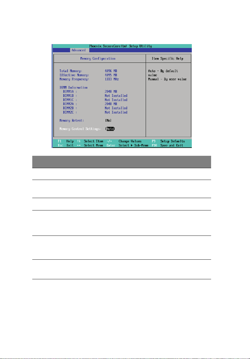
Memory Configuration
Parameter Description Options
Total Memory Total size of system memory detected during POST.
Effective Memory Total size of effective memory detected during
POST.
Memory Frequency Total memory frequency detected during POST
DIMM Information
DIMM 1A/1B/1C/2A/
2B/2C slots
Memory Retest Select whether to delete the historical
Memory Control
Setting
The size of memory installed on each of the DDR3
DIMM slots.
Yes
memory data log. System memory will
be retested on the next boot-up.
Memory control setting. Auto
No
Manual
Page 83

ATA Controller Configuration
65
Parameter Description Options
Serial ATA Enables or disables the Serial ATA. Enabled
Disabled
Page 84

66
Parameter Description Options
4 System BIOS
SATA Mode
Selection
SATA Port
0/1/2/3/4/5
Type Press the space bar to configure this
When set to IDE, the SATA controller
disables its RAID and AHCI functions
and runs in the IDE emulation mode.
You will not have access to the RAID
setup utility.
When set to AHCI, the SATA
controller enables its AHCI
functionality. However, its RAID
functions will be disabled and you
will not be able to access the RAID
setup utility at boot time. For more
information on AHCI, refer to the
SATA AHCI Mode BIOS feature.
When set to RAID, the SATA
controller enables both its RAID and
AHCI functions. You are allowed to
access the RAID setup utility at boot
time.
Press <Enter> to configure the advanced HDD.
parameter.
IDE
RAID
ACHI
Auto
None
CD-ROM
Other ATAPI
User
Multisector
Transfer
LBA Mode
Control
32-bit I/O Enables/disables 32-bit IDE data
Specifies the number of sectors per
block for multiple sector transfers.
Enabling the LBA causes Logical Block
Addressing to be used in place of
Cylinders, Heads & Sectors (CHS).
transfers.
Disabled
2 Sectors
4 Sectors
8 Sectors
16 Sectors
Enabled
Disabled
Enabled
Disabled
Page 85

Parameter Description Options
67
Transfer Mode Selects the method for moving data
Ultra DMA
Mode
to/from the drive.
Selects the Ultra DMA mode for
moving data to/from the drive.
Standard
Fast PIO 1
Fast PIO 2
Fast PIO 3
Fast PIO 4
FPIO 3/DMA 1
FPIO 4/DMA 2
Disabled
Mode 0
Mode 1
Mode 2
Mode 3
Mode 4
Mode 5
Mode 6
Page 86

68
Serial Port Configuration
Parameter Description Options
4 System BIOS
Serial Port A/B When set to Enabled, the system
allows you to configure the serial
port settings.
When set to Auto, the system allows
the server BIOS or OS to select a
configuration.
When set to Disabled, the system
will not display any configuration
for the serial port.
Base I/O Address Selects the base I/O address and IRQ
setting for the selected serial port.
Enabled
Disabled
Auto
3F8/IRQ4
2F8/IRQ3
3E8/IRQ4
2E8/IRQ3
Page 87

PCI Configuration
Parameter Description Options
69
PCI-E_1/2
Option ROM
Onboard LAN
iSCSI Boot ROM
Onboard
NIC1/NIC2
Onboard NIC1/
NIC2 ROM
When enabled, this setting will
initialize the device expansion ROM
for the related PCI slot.
Enables or disables the load of
embedded Internet SCSI option ROM
for the onboard LAN controller.
Enables or disables the onboard LAN
controller.
Enables or disables the LAN option
ROM.
Enabled
Disabled
Enabled
Disabled
Onboard LAN
iSCSI Boot ROM
Enabled
Disabled
Enabled
Disabled
Page 88
70
4 System BIOS
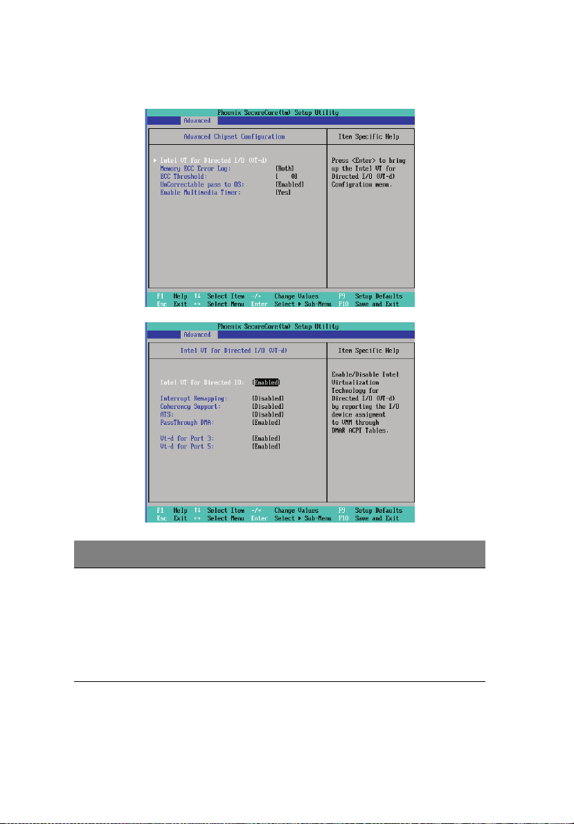
Advanced Chipset Configuration
Parameter Description Options
Intel VT for
Directed IO
Intel VT-d improves security and
reliability of the systems and also
improves performance of I/O devices
in virtualized environment.
Enables or disables Directed IO
supporting Intel Virtualization
Technology.
Enabled
Disabled
Page 89

Parameter Description Options
71
Memory ECC
Error Log
ECC Threadholds Identifies the ECC threadholds. Use
UnCorrectable
pass to OS
Enabled
multimedia
Timer
Interrupt
Remapping
Coherency
Support
ATS Enables or disables ATS. Enabled
Identifies the memory ECC error log. Disabled
Correctable
Error
Uncorrectable
Error
Both
“+” and “-“ keys to adjust the desire
value.
When set to Enabled, the system will
skip the error and boot up
automatically.
Enables or disables the onboard
graphic device.
Enables or disables the Interrupt
Remapping.
Enables or disables the Coherency
Support.
Enabled
Disabled
Yes
No
Enabled
Disabled
Enabled
Disabled
Disabled
PassThrough
DMA
VT-d for Port 3/5 Enables and disables VT-d support for
Enables or disables PassThrough
DMA.
port 3 and port 5 through ATSR
structures in the ACPI Tables.
Enabled
Disabled
Enabled
Disabled
Page 90

72
4 System BIOS
System Acoustic & Performance Configuration
Parameter Description Options
Open-loop Thermal
Throttle
Temperature
Chassis inlet
Temperature Rise
Air speed to the
DIMMs
System Altitude
Pitch between
DIMMs
Enables or disables Open-loop
Thermal Throttle.
User-defined items. Use the number keys to input
the desired value.
Enabled
Disabled
Page 91

Parameter Description Options
73
Close-loop Thermal
Throttle
Temperature
hysteresis
Temperature
guardband
Temperature
Chassis inlet
Temperature Rise
Air speed to the
DIMMs
System Altitude
Pitch between
DIMMs
FAN Speed Control Enables or disables fan speed control. Enabled
Enables or disables Close-loop
Thermal Throttle.
User-defined items. Use the number keys to input
the desired value.
Enabled
Disabled
Disabled
Page 92

74
4 System BIOS
Power menu
Parameter Description Options
Deep Power Off
Mode
Power On by RTC
Alarm
Power On by PCI
& PCIE
Power On by
Modem Ring
Wake Up by USB
KB/Mouse
Enables or disables the Deep Power Off
Mode.
Sets the system to wake up from an
RTC alarm.
Sets the system to wake up when a PCI
or PCIE device is detected.
Sets the system to wake up when an
incoming call is detected on the
modem.
Sets the system to wake up when
action on the USB keyboard or mouse
is detected.
Enabled
Disabled
On
Off
Enabled
Disabled
Enabled
Disabled
Enabled
Disabled
Page 93

Parameter Description Options
75
After Power
Failure
Defines the power state to resume to
after the system shuts down due to
interruption in AC power.
When set to Last State, the system will
return to the active power state prior
to the shutdown.
When set to Stay Off, the system
remains off after power shutdown.
Last State
Stay Off
Power ON
Page 94

76
4 System BIOS
Security menu
The Security menu allows you to safeguard and protect the system
from unauthorized use by setting up access passwords.
There are three types of passwords that you can set:
• Supervisor password
Entering this password will allow the user to access and change all
settings in the Setup Utility.
• User password
Entering this password will allow a user to enter the Setup menus,
but not have the rights to make changes.
• Power-on password
When the Password on Boot field is enabled, a password will be
required to boot up the server.
Parameter Description Options
Supervisor
Password Is
User Password Is This parameter indicates whether a user
This parameter indicates whether a
supervisor password has been assigned.
password has been assigned.
Clear
Enabled
Clear
Enabled
Page 95

Parameter Description Options
77
Set Supervisor
Password
Set User
Password
Password On
Boot
Power Button
Lockout
Clear Case Open
Status
TPM Support TPM, stands for Trusted Platform Module.
Current TPM
Sate
Change TPM
State
Press <Enter> to configure the supervisor password.
Press <Enter> to configure the user password.
Select Enabled to activate security check
during POST.
Press <Enter> to clear the case open
status.
A Trusted Platform Module provides
function for secure generation of
cryptographic keys, the ability to limit the
use of cryptographic keys, as well as a
hardware pseudo-random number
generator.
Displays the current TPM State status.
Changes the TPM state. No
Enabled
Disabled
Enabled
Disabled
Enabled
Disabled
Change
Enable &
Activate
Deactivate
& Disable
Clear
Page 96

78
4 System BIOS
Setting a system password
1 Use the up/down keys to select a password parameter (Set
Supervisor Password or Set User Password), then press <Enter>.
A password box will appear.
2 Type a password then press <Enter>.
The password may consist of up to eight alphanumeric characters
(A-Z, a-z, 0-9).
3 Retype the password to verify the first entry then press <Enter>
again.
4 Press <F10>.
5 Select Yes to save the new password and close the Setup Utility.
Changing a system password
1 Use the up/down keys to select a password parameter (Set
Supervisor Password or Set User Password), then press <Enter>.
2 Type the original password then press <Enter>.
3 Type a new password then press <Enter>.
4 Retype the password to verify the first entry then press <Enter>
again.
5 Press <F10>.
6 Select Yes to save the modified password and close the Setup
Utility.
Removing a system password
1 Use the up/down keys to select a password parameter (Set
Supervisor Password or Set User Password), then press <Enter>.
2 Enter the current password then press <Enter>.
3 Press <Enter> twice without entering anything in the new and
confirm password fields.
After doing this, the system automatically sets the related
password parameter to Clear.
Page 97

Server Management menu
Parameter Description
79
System Information Displays basic system ID information, as well as BIOS
Console Redirection Displays console redirection-related settings.
Event Log
Configuration
firmware versions.
Press <Enter> to access the related submenu.
Press <Enter> to access the related submenu.
Displays basic system event log information.
Press <Enter> to access the related submenu.
Page 98

80
4 System BIOS
System Information
The System Information submenu is a simple display page for basic
system ID information, as well as BIOS firmware versions. Items on this
window are non-configurable.
Parameter Description Options
BMC IP Address
Source
Configures the BMC IP address source. Static
DHCP
Page 99

Parameter Description Options
IP Address Determines the IP address.
IP Subnet Mask Determines the IP subnet mask.
Default Gateway Determines the default gateway address.
Console Redirection
81
Parameter Description Options
BIOS
Redirection
Port
Flow Control Assigns control for the console
Baud Rate Selects the baud rate for console
Selects whether to enable console
redirection.
Console redirection enables users to
manage the system from a remote
location.
redirection flow.
redirection.
Serial Port A
Serial Port B
Disabled
None
XON/OFF
CTS/RTS
9600
19.2K
38.4K
Page 100

82
Parameter Description Options
4 System BIOS
Terminal
Type
Continue
C.R. After
POST
Selects a terminal type to be used for
console redirection.
Selects whether to enable console
redirection after POST.
Event Log Configuration
VT100
VT100 8bit
PC-ANSI 7bit
VT100+ VT-UTF8
ASCII
On
Off
Parameter Description Options
Assert NMI on
SERR
Assert NMI on
PERR
Clear all Event
Logs
Enables the SERR signal to be reported as
a critical event via NMI.
Enables the PERR signal to be reported as
a critical event via NMI. The Assert NMI on
SERR option must also be enabled.
Deletes all DMI event log entries during the next system
start-up.
Enabled
Disabled
Enabled
Disabled
 Loading...