

Page 1
$FHU $OWRV %
System Guide
Page 2

&RS\ULJKW
Copyright 1998 by A c er Incorporated. All rights reserved. No part of this publication may be reproduced, transmit ted, transcribed, stored in a retrieval system, or translated into any language or computer language, in any form or by any means, electronic, mechanical, magnetic, optical, chemical, manual or otherwise, without the prior written permission of t his company.
'LVFODLPHU
This company makes no representations or warranties, either
expressed or implied, with respect to the contents hereof and
specifically disclaims any warranties, merchantability or fitness for
any particul ar pur pose. Any sof tware descri bed in t his m anual i s sold
or licensed "as is". Should the programs prove defective following
their purchase, t he buyer (and not thi s company, i ts distri butor, or its
dealer) assumes the enti re cost of all necessary serv i ci ng, repai r, and
any incident al or consequenti al dam ages resulti ng f rom any defect i n
the software. F urther, this com pany reserves the ri ght to rev ise this
publication and to make changes from time to time in the contents
hereof without obligation to notify any person of such revision or
changes.
All brand and product names mentioned in this manual are trademarks and/or registered
trademarks of their respective companies.
ii
Page 3

,03257$17 6$)(7<
,16758&7,216
1. Read these instructions carefully. Save these instructions for
future reference.
2. Follow all warnings and instructions marked on the product.
3. Unplug this product fr om the wal l outl et bef ore cleani ng. Do not
use liquid cleaners or aerosol cleaners. Use a damp cloth for
cleaning.
4. Do not use this product near water.
5. Do not place this product on an unstable cart, stand, or table.
The product may fal l, causing serious dam age to the product.
6. Slots and openings in the cabinet and the back or bottom are
provided for ventilation; to ensure reliable operation of the
product and to prot ect it f rom over heating, these openings m ust
not be blocked or covered. The openings should never be
blocked by placing the product on a bed, sofa, rug, or other
similar surface. This product should never be placed near or
over a r adiator or heat register , or i n a buil t-i n i nstallat ion unless
proper v entilation is provided.
7. This product should be oper ated from the type of power indicated
on the marki ng label. If you are not sure of the type of power
available, c onsul t your dealer or local power company.
8. This product is equipped with a 3-wire grounding-type plug, a
plug hav ing a thir d (grounding) pin. This plug will only fit into a
grounding-type power outlet. This i s a safety f eature. If you are
unable to insert the plug into the outlet, contact your electri cian
to replace your obsolete out l et. Do not def eat the pur pose of t he
grounding-type plug.
iii
Page 4

9. Do not allow anythi ng to rest on the power cord. Do not locate
this product where persons will walk on the cord.
10. If an ex tension c ord i s used with this product , m ak e sure that the
total amper e rating of the equipment plugged into the ex tension
cord does not exceed the extension cord ampere rating. Also,
make sure that the total rating of all products plugged into the
wall outlet does not exceed 15 am per es.
11. Nev er push objects of any kind i nto this product through cabinet
slots as they may touch dangerous voltage points or short out
parts that could result in a fire or electric shock. Never spill
liqui d of any kind on the product.
12. Do not attempt to service this product yourself, as opening or
remov i ng cov er s may ex pose you to dangerous v ol t age point s or
other risks. Refer all servicing to qualified service personnel.
13. Unplug this product from the wall outlet and refer servicing to
qualified service personnel under t he followi ng c onditions:
a. When the power cord or plug is damaged or fr ay ed
b. If liqui d has been spil led into the pr oduc t
c. If t he pr oduc t has been exposed to rain or water
d. If the pr oduct does not oper ate norm al l y when t he oper ati ng
instructions are followed. Adjust only those controls that are
covered by the operating instructions since improper
adjustment of other controls m ay result in dam age and will
often require extensive work by a qualified technician to
restore the product to normal c ondition.
e. If the product has been dropped or the cabinet has been
damaged
f. If the product exhibits a distinct change in performance,
indicat ing a need for service
14. Replace battery with the sam e type as the product's battery we
recomm end. Use of anot her batt ery m ay present a ri sk of f i re or
explosion. Refer battery replacement to a qualified serviceman.
iv
Page 5

15. W arning! Battery may ex plode if not handled properly. Do not
recharge, disassemble or dispose of in fire. Keep away from
children and dispose of used battery promptly.
16. Use only the proper t ype of power supply cord set (provided i n
your keyboard/manual accessories box) for thi s uni t. It should be
a detachable type: UL listed/CSA certified, type SJT, rated 6A
125V minimum, VDE approved or its equivalent. Maximum
length is 15 feet (4.6 meters).
v
Page 6

)&& &ODVV % 5DGLR )UHTXHQF\
,QWHUIHUHQFH 6WDWHPHQW
Note:
This equipm ent has been tested and found to comply wi th the l imits
for a Cl ass B digital device, pur suant to Part 15 of FCC Rules. These
lim its are designed to pr ovide reasonable protec tion against harmf ul
interf erence in a residential installati on. This equipment generates,
uses, and can radiate radi o f requency energy and, i f not i nstal led and
used in accordance with the instructions, may cause harmful
interference to radio communications. However, there is no
guarantee that interfer enc e will not occur in a particular installation. If
this equipment does cause harmful i nterferenc e to radio or t elev ision
reception, which can be determ ined by turning t he equipm ent of f and
on, the user is encouraged to try to corr ect the i nterf erence by one or
more of the following measures:
1. Reorient or r elocate the receiving antenna.
2. Increase the separation between the equipment and receiver.
3. Connect the equipment into an outlet on a circuit different from
that to which t he r ec eiver is connected.
4. Consult the dealer or an experienced radio/telev ision technician
for hel p.
Notice 1:
The changes or modifications not expressly approved by the party
responsible for compl iance could v oid the user's authori ty to operate
the equipm ent.
Notice 2:
Shielded interface cables, if any, must be used in order to comply
with the emission limits.
vi
Page 7

$ERXW WKLV 0DQXDO
Getting Started
This system gui de aims to giv e you al l the necessary inform ation to
enable you to operat e the Altos 9100B system.
Manual Structure
This system gui de c onsi sts of four chapters.
Chapter 1 System Ho usi n g
This chapter describes the assembly and disassembly of the
system housing. It also shows you how to install housing
components.
Chapter 2 System Board
This chapter descri bes the main board. Also, It i ntroduces t he
system’s unique f eatures and powerful architecture.
Chapter 3 CPU Board
This chapter describes the dual-processor CPU board. It
includes the CPU board jumper settings and cache and system
memor y configurati ons. Step-by-step instruct ions tell you how
to install the CPUs and memory modul es.
Chapter 4 BIOS Utility
This chapter explains the BIOS parameter functions. It tells
how to configur e the system by setti ng the parameters.
vii
Page 8
Conventions
The following are the conventi ons used in t his manual:
Text entered by user
Option Items
, , , etc. Represent the actual k ey s that you
Represents text input by the user.
Represents options that you can
select on the screen.
have t o pr ess on the keyboar d.
NOTE
Gives bits and pieces of additional
infor mation related to the cur r ent
topic.
CAUTION
Gives precautionary measures to
avoid possible hardware or
software problems.
TIP
Tells how to accomplish a
procedure with m inimum steps
through li ttle shortcut s.
viii
Page 9

7DEOH RI &RQWHQWV
Chapter 1 System Housing
Positioning the System Housi ng................................................0-1
Standalone System ......................................................0-1
Against a Wall.............................................................. 0-2
Transporting the System........................................................... 0-3
Features ................................................................................0-4
Front Panel .................................................................0-4
Rear Panel ................................................................. 0-5
Internal Structure.......................................................... 0-6
Opening the Housing P anels.....................................................0-7
Upper Front Panel ........................................................0-7
Lower Front Panel ........................................................0-8
Left Panel .................................................................0-9
Installing Disk Drives...............................................................0-10
3.5-inch Drive............................................................. 0-10
5.25-inch Drive........................................................... 0-12
Hard Disk ...............................................................0-13
Upgrading to Two Redundant Power Supply Modules ............. 0-15
Removing the Existing Power Supply.........................0-15
Installing the Power Supply Modules ..........................0-19
Installing a System Board ....................................................... 0-22
Installing an Expansion Boar d................................................. 0-23
Installing a CPU Board ............................................................ 0-25
Connecting External Devices.................................................. 0-28
Connecting a Monitor ................................................. 0-28
ix
Page 10

Connecting a Keyboar d .............................................. 0-29
Connecting a Mouse................................................... 0-30
Connecting a Printer................................................... 0-31
Complet e S y stem Connections ............................................... 0-32
Chapter 2 System Board
Major Com ponents.................................................................... 1-3
System Board Layout................................................................1-4
Jumpers and Connectors .......................................................... 1-5
Jumper Settings........................................................... 1-6
Connector Funct ions.....................................................1-6
ESD Precautions.......................................................................1-8
Video Mem or y Upgr ade ............................................................ 1-9
Supported Video Resol utions........................................ 1-9
Installing Expansion Cards...................................................... 1-12
Installing a PCI Card................................................... 1-12
Installing an ISA Card.................................................1-12
ASM Pro.................................................................................1-14
Remote Di agnostic Management ............................................ 1-15
Installing an RDM Module........................................... 1-15
Error Messages....................................................................... 1-16
Software Error Messages............................................1-16
System Error Messages..............................................1-16
Correcting Error Condit ions ........................................ 1-18
Chapter 3 CPU Board
x
Page 11

CPU Board Layout....................................................................2-1
CPU Board Jumper s and Connect or s........................................ 2-2
Jumper Settings........................................................... 2-2
Connector Funct ions.....................................................2-3
Memory Upgrade ......................................................................2-4
Memory Configurations ................................................2-4
Installing a DIMM..........................................................2-5
Removing a DIMM....................................................... 2-6
Reconfiguring the System.............................................2-7
Installing a Pentium II Processor............................................... 2-8
Installing the Processor Heatsink and F an ....................2-8
Installing the Processor Module.................................. 2-11
Uninstalling the Processor ....................................................... 2-13
Removing the Processor from the Slot....................... 2-13
Removing the Proc essor Heatsink and Fan................2-14
Installing the Termination Board..............................................2-16
CPU Board Installation ............................................................ 2-17
Chapter 4 BIOS Utility
Entering Setup.......................................................................... 3-2
System Information...................................................................3-3
Processor..................................................................... 3-4
Processor Speed..........................................................3-5
Bus Frequency .............................................................3-5
Internal Cache..............................................................3-5
External Cache............................................................. 3-5
Floppy Drive A .............................................................3-5
xi
Page 12

Floppy Drive B .............................................................3-5
IDE Primary Channel Master ........................................3-6
IDE Primary Channel Slave.......................................... 3-6
Total Memory...............................................................3-6
Serial Port 1...................................................................... 3-6
Serial Port 2...................................................................... 3-6
Parallel Port ................................................................. 3-6
Pointing Device............................................................ 3-7
Memory Parity Mode....................................................3-7
Onboard USB...............................................................3-7
Product Informat ion ..................................................................3-8
Product Nam e .............................................................. 3-8
System S/N .................................................................3-8
Main Board ID.............................................................. 3-9
Main Board S/N............................................................3-9
System BIOS Version...................................................3-9
System BIOS ID........................................................... 3-9
BIOS Release Date...................................................... 3-9
Disk Driv es ............................................................................. 3-10
Floppy Drives............................................................. 3-12
IDE Drives......................................................................... 3-12
Power Management................................................................ 3-16
Power Management Mode.......................................... 3-16
Startup Configuration.............................................................. 3-18
Fast POST Mode........................................................ 3-18
Silent Boot......................................................................... 3-19
Num Lock After Boot.................................................. 3-19
xii
Page 13

Memory Test.............................................................. 3-19
Initialize SCSI Before IDE ..........................................3-19
System Boot Drive ..................................................... 3-20
Boot from IDE CD-ROM.............................................3-20
Advanc ed Configurat ion.......................................................... 3-21
Onboard Devices Configuration.................................. 3-22
PnP/PCI Sy stem Configuration................................... 3-28
Memory/ Cac he Configurat ion..................................... 3-33
Non-PnP ISA Device Configurat ion............................ 3-35
System Security Setup............................................................3-39
Disk Drive Control ...................................................... 3-39
Setup Password..........................................................3-40
Power-on Password.................................................... 3-43
Date and Time........................................................................ 3-44
Date .......................................................................... 3-45
Time ..........................................................................3-45
Remote Di agnostic Configuration............................................ 3-46
Load Setup Default Settings.................................................... 3-47
Abort Sett ings Change............................................................3-48
Leaving Setup......................................................................... 3-49
xiii
Page 14
Chapter 0 System Housing
This installation guide describes the features of the system housing
and tells you how to install the basic system com ponent s such as disk
driv es, system board, or expansion boards. Descripti ve illustrations
accompany t he installat ion procedures.
If you receive a complete system, the basic
components are already ins talled.
Positioning the System Housing
Standalone System
For a standalone system, rotate the legs outward to stabilize the
housing.
Getting Started 0-1
Page 15
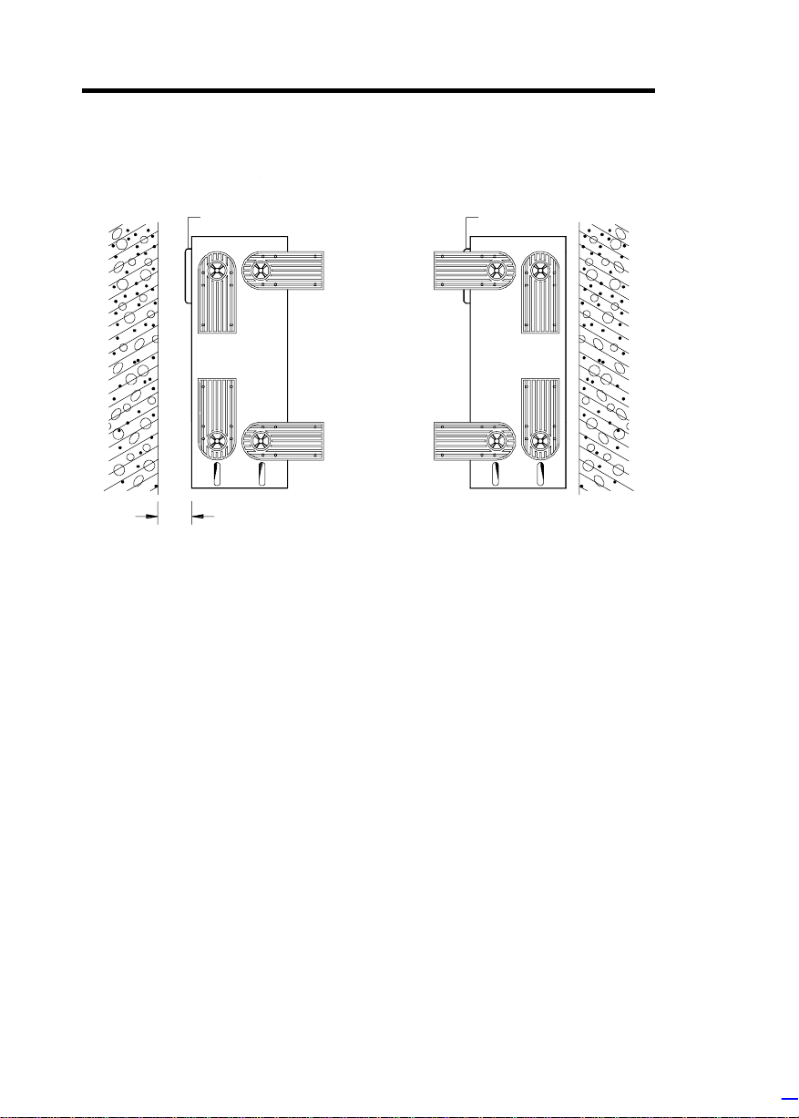
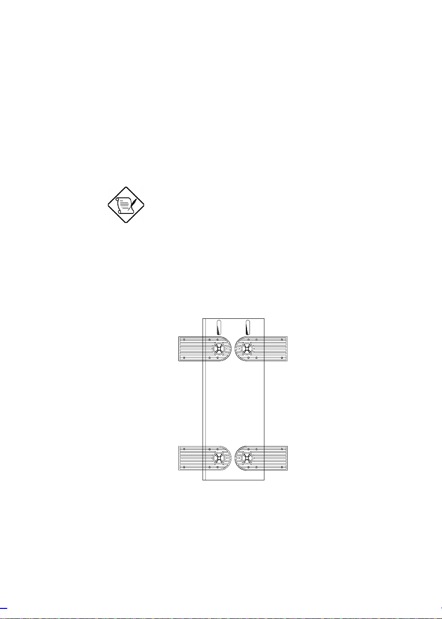
Against a Wall
Figure A
Fans
5~10 cm
Figure B
Fans
Fans Facing a Wall
When standi ng t he housing with t he f ans facing a wall, leave a space
of 5~10 c m from the wall to allow air ci r c ulation, then position the legs
as in Figure A.
Fans Facing Out
When standi ng the housing with the f ans faci ng out, y ou can put the
system close to t he wall and position t he legs as in Figure B.
0-2 Altos 9100B System Guid e
Page 16
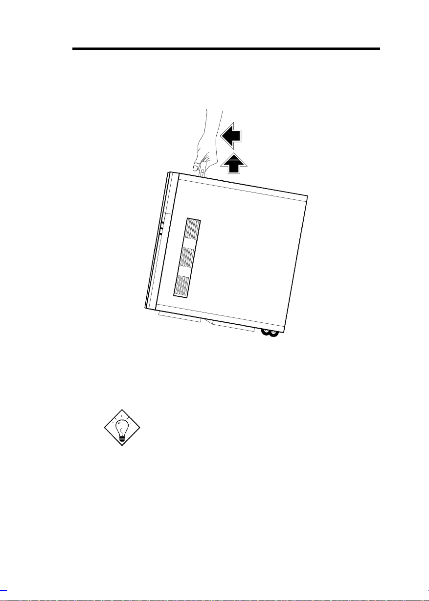
Transporting the System
The housing has a handle on top and two wheels behind the feet t o
facilitate moving to short distances.
Rotate the feet inward before moving the
housing.
When t ransporting t he housing, pul l out t he handle, at the sam e ti me
lifting the unit front a few inches from the floor. Slide the housing
forward with the wheel s supporting the rear.
System Housing 0-3
Page 17
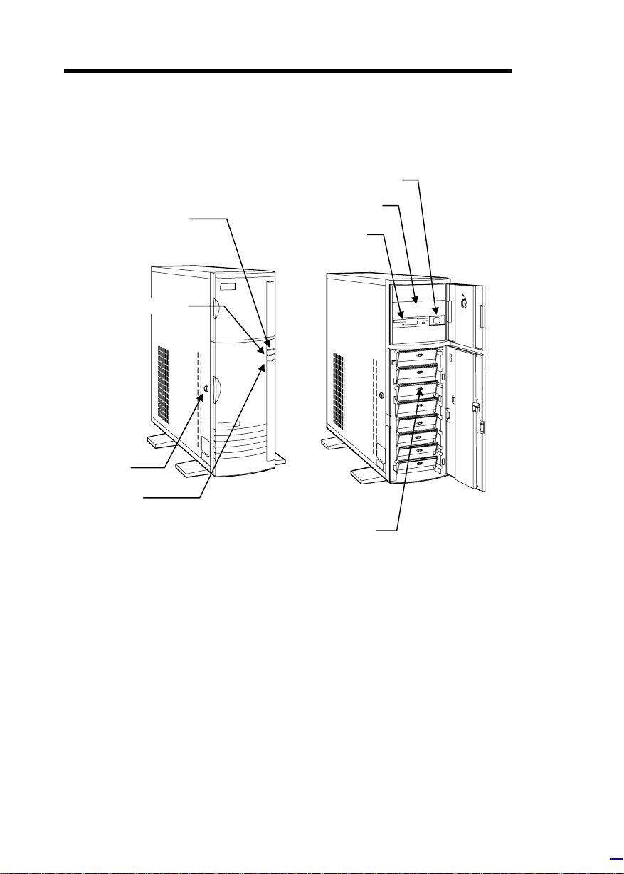
Features
k
D
D
y
e
s
D
Front Panel
Power LE
Hard Disk Drive LE
Keyloc
RDM LE
Power Switch
5.25-inch Drive Ba
3.5-inch Driv
SCSI Hard Disk Drive Tray
0-4 Altos 9100B System Guid e
Page 18
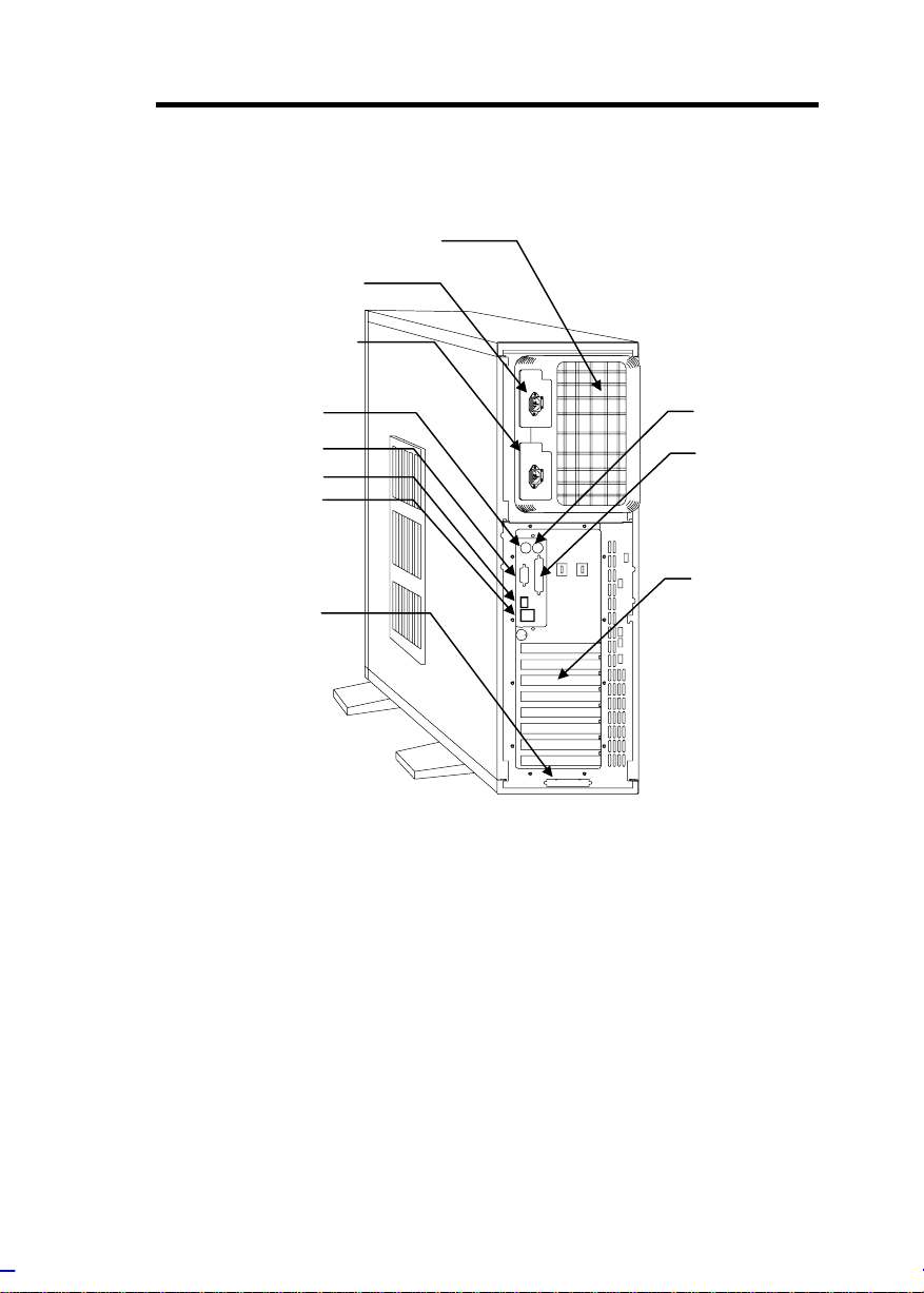
Rear Panel
t
t
r
t
r
2
Power Socket 1
Power Socket
Power Supply Bays
Keyboard Por
Video Por
RJ-45 Connecto
USB Connecto
SCSI Expansion Slo
Mouse Port
Parallel Port
Expansion Slots
System Housing 0-5
Page 19
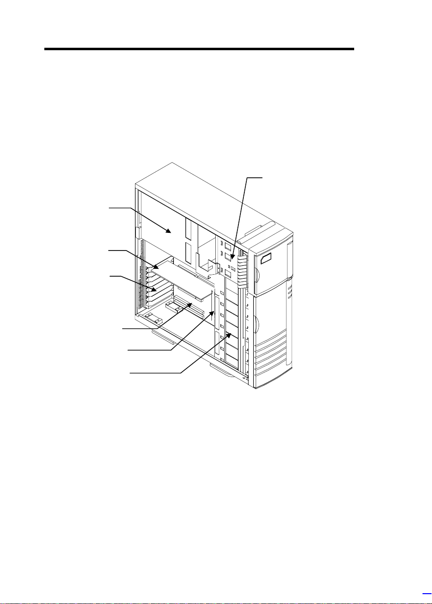
Internal Structure
d
d
d
The fol l owing f i gure shows the housing internal struc ture and som e of
the basic system components.
3.5-inch and 5.25-inch
Power Supply
Metal Plate
(covering two
redundant
power supply
modules)
CPU Boar
Expansion Slot
Brackets
System Boar
Backplane Boar
Drive Bays
SCSI Drive Trays
0-6 Altos 9100B System Guid e
Page 20
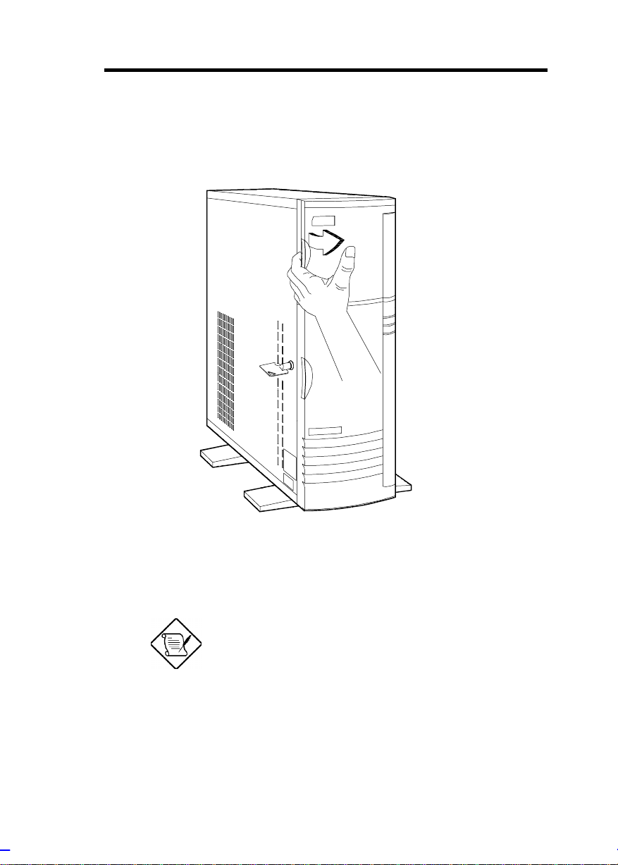
Opening the Housing Panels
Upper Front Panel
Hold the left edge of the upper f ront panel to open i t and gain ac cess
to the diskette drive bays.
The housing keys are inside the front panel.
System Housing 0-7
Page 21
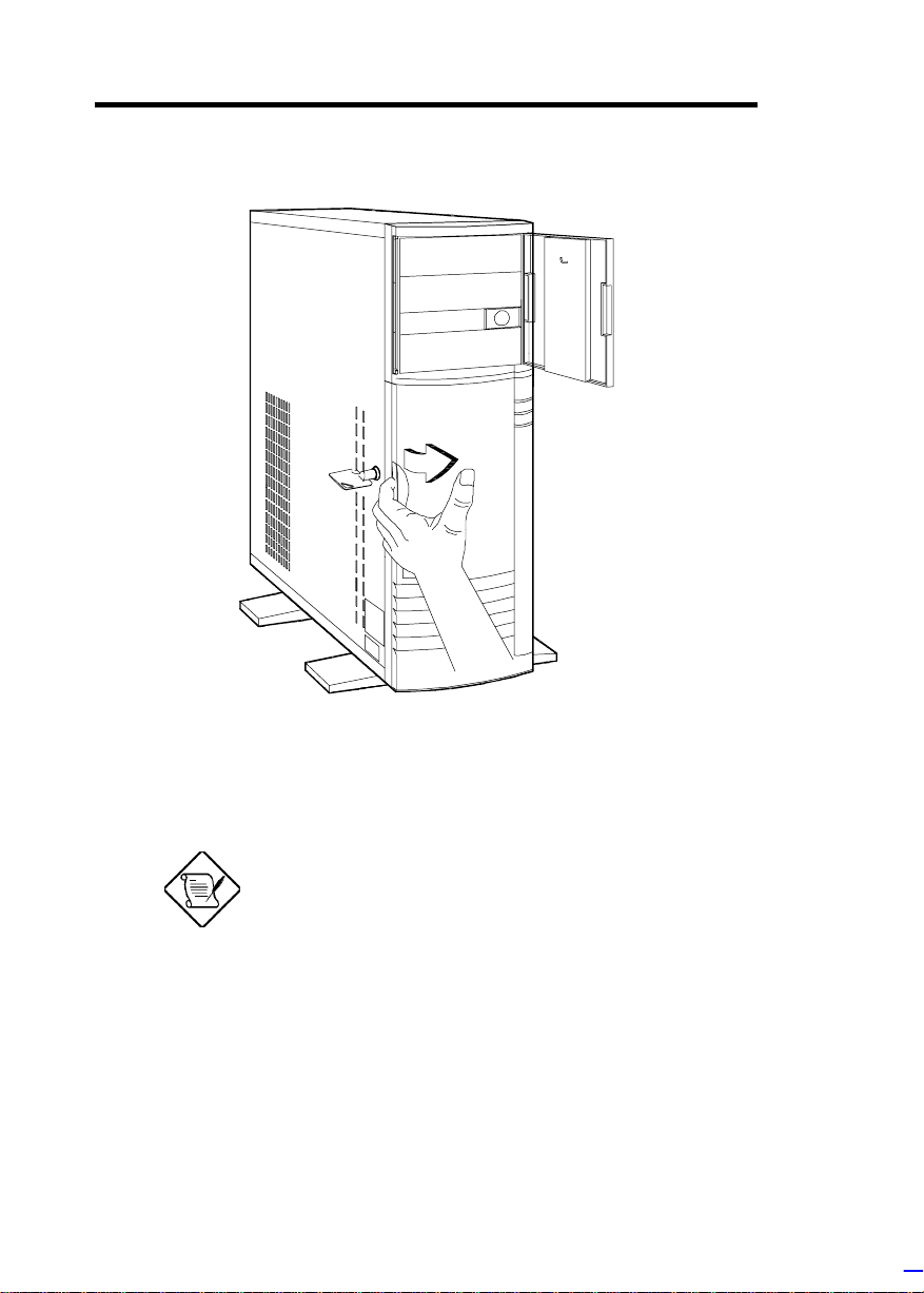
Lower Front Panel
Unlock the housing wit h the key. Pull the lower panel to access the
drive trays.
You cannot remove the key after you have
unlocked the housing. You can remove it
only when you lock t he hous ing again.
0-8 Altos 9100B System Guid e
Page 22
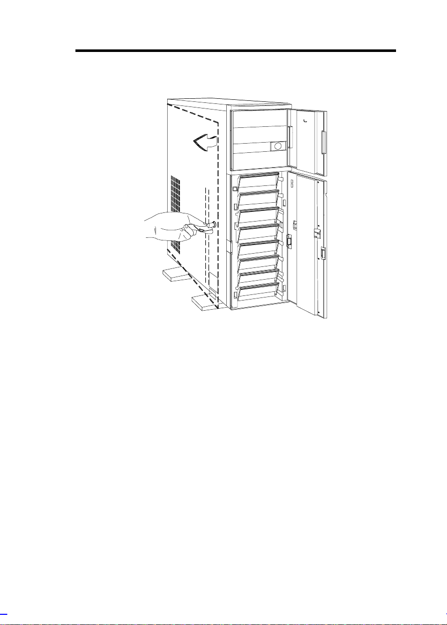
Left Panel
Pull on t he key to swing the left panel open. If necessary, you may
use a screwdriver t o pr y open the panel.
System Housing 0-9
Page 23
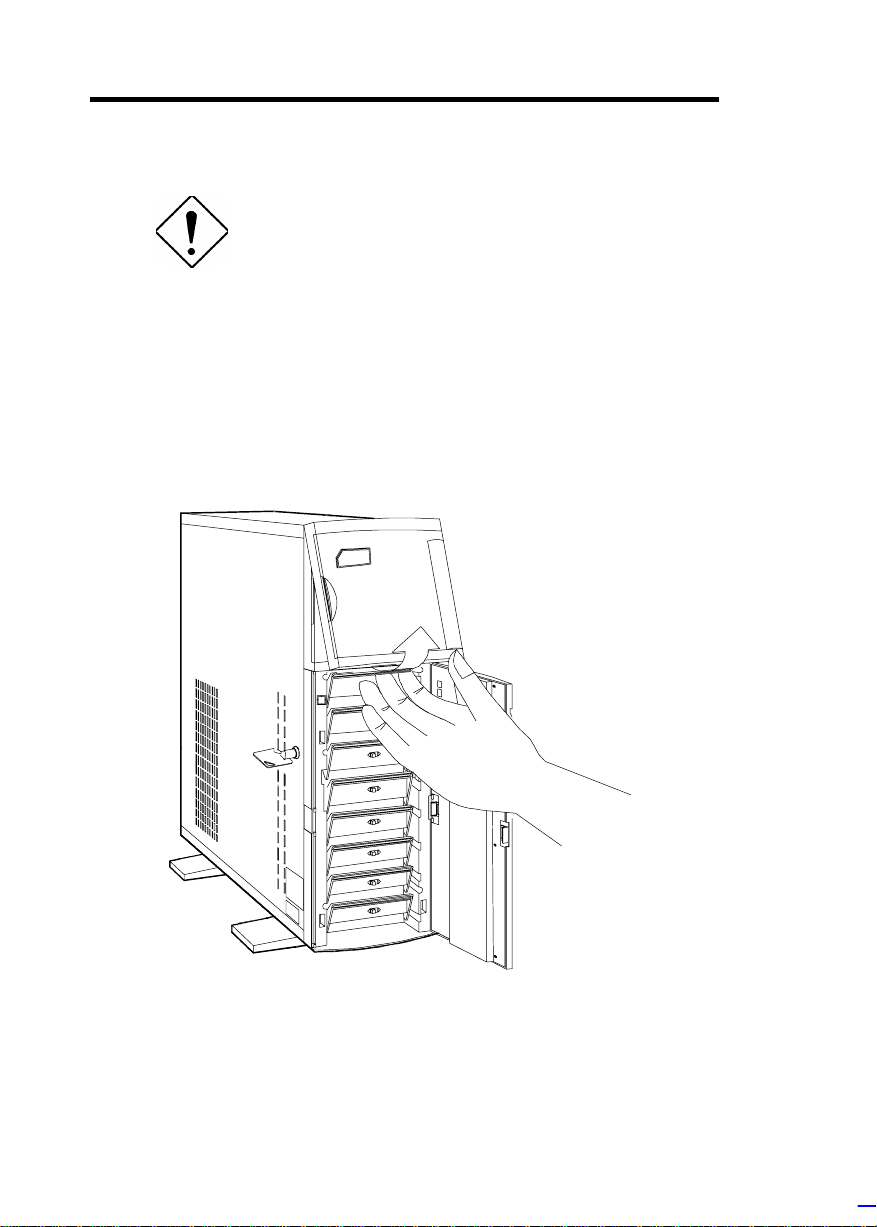
Installing Disk Drives
Turn off the power switch and unplug the
power cord before installing or removing
diskette drives .
3.5-inch Drive
1. Open the lower front panel.
2. Remove the upper panel including its fram e by pr essing the latch
underside and pulling the panel out.
0-10 Altos 9100B System Guid e
Page 24
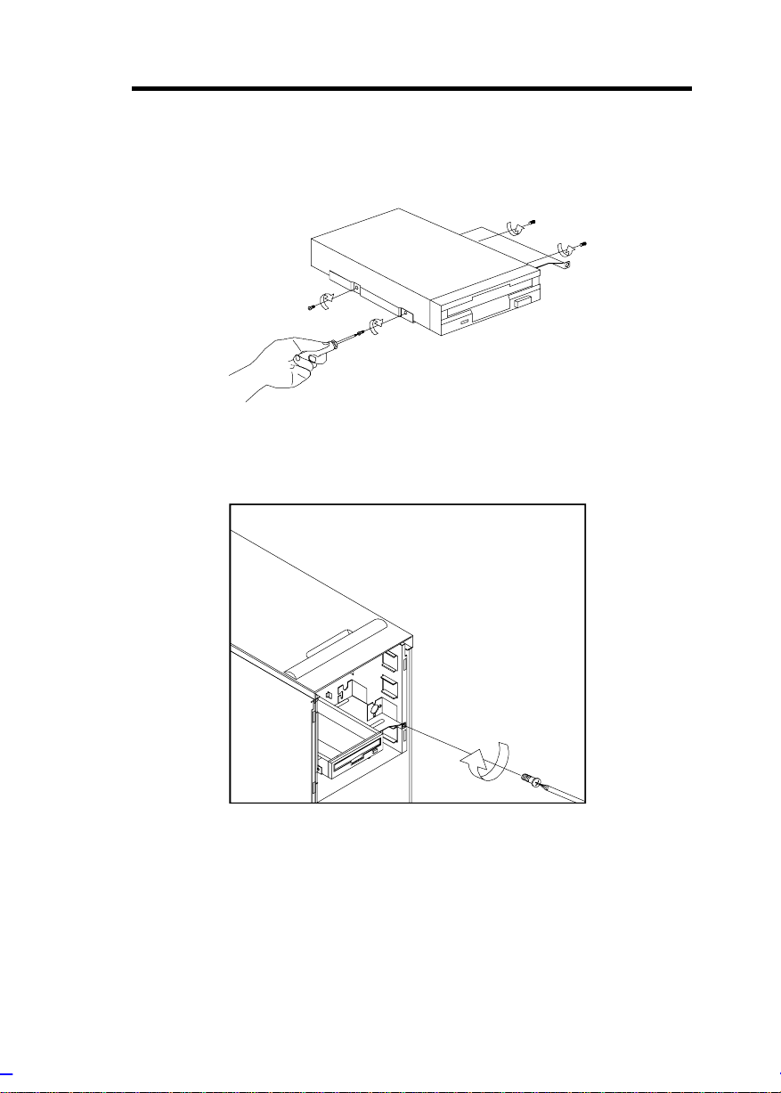
3. Remove the screw attaching the 3.5-inch drive frame to the
housing.
4. Secure a 3.5-i nc h dr ive on the frame with four screws.
5. Insert the dri ve into the drive bay and secure it wi th a screw.
6. Connect the disket te drive cables.
System Housing 0-11
Page 25
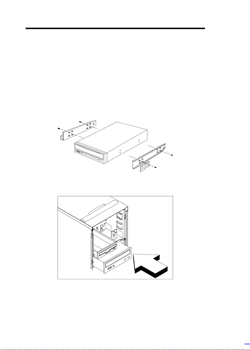
5.25-inch Drive
You may install a CD-ROM, digital audio tape (DAT), hard disk,
diskette drive or any other 5.25-inch device into the dri ve bay.
1. Open the lower front panel.
2. Remove the upper panel including its fram e by pr essing the latch
underside and pulling the panel out.
3. Secure the dri ve guides on the si des of a 5.25-inch dr ive.
4. Insert the dri ve into the drive bay.
5. Connect the signal and power cables to the drive.
0-12 Altos 9100B System Guid e
Page 26
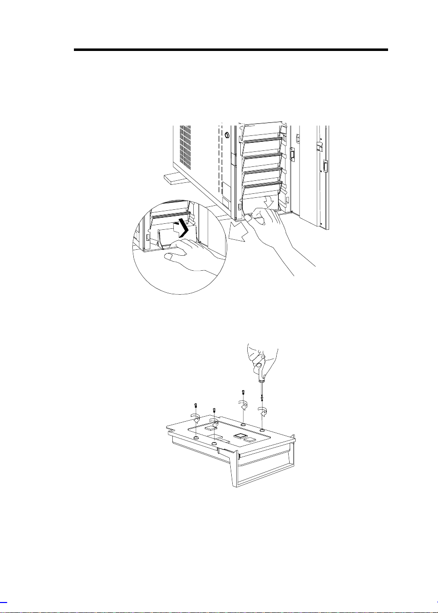
Hard Disk
1. Pull out a dr ive tray.
2. Place a hard di sk on t he tray and secure it wit h four screws.
System Housing 0-13
Page 27
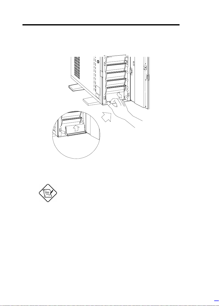
3. Insert the tray back into the housing. Make sure to push back
the drive tray handle in place before pushing the tray in
completely. The tray does not fit in if the handle is not in place.
4. Connect the hard di sk cables.
If you installed a SCSI backplane board into
the housing, see the backplane board
manual for hard disk installation instruct ions .
0-14 Altos 9100B System Guid e
Page 28
Upgrading to Two Redundant Power Supply
Modules
Follow the instructions in this section when you want to upgrade to
two 420W redundant power supply modules.
To reduce the risk of electric shock, make
sure to disconnect all power supply cables
from the wall socket before opening the
system housing.
Removing the Existing Power Supply
1. Unplug the AC power cable from the wall socket, then remove
the plastic fan cover on the rear panel .
2. Open and remove the lower front and left doors. See the
Opening the Housing P anels section for more information.
3. Remove the three screws that secure the right door.
DO NOT open the RIGHT door at this
moment! Doing so will damage the power
sharing board and cables attached to its
inner side.
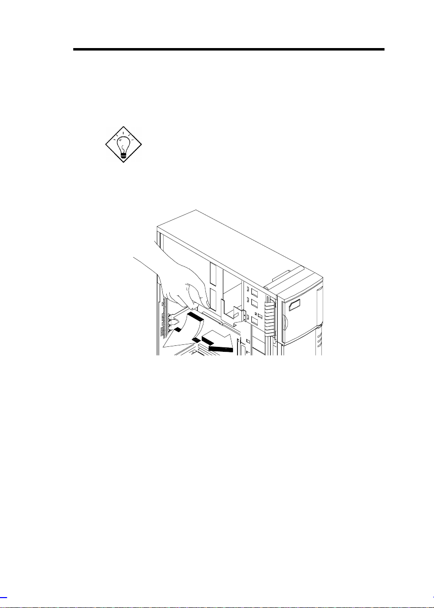
4. Unplug the connect or s
- from the power supply to the power sharing board
- from the power sharing board to the system board
- from the power sharing board to the disk drives
- from the fans to the system board
Remember where you unplugged each c onnector . You will have
to reconnect t hem later.
System Housing 0-15
Page 29
5. When f inished disconnecti ng all the cables att ached to the i nner
side of the r ight door, open and remove the right door.
Be careful when opening and removing the
right door to avoid damaging the power
sharing board attached to its inner side.
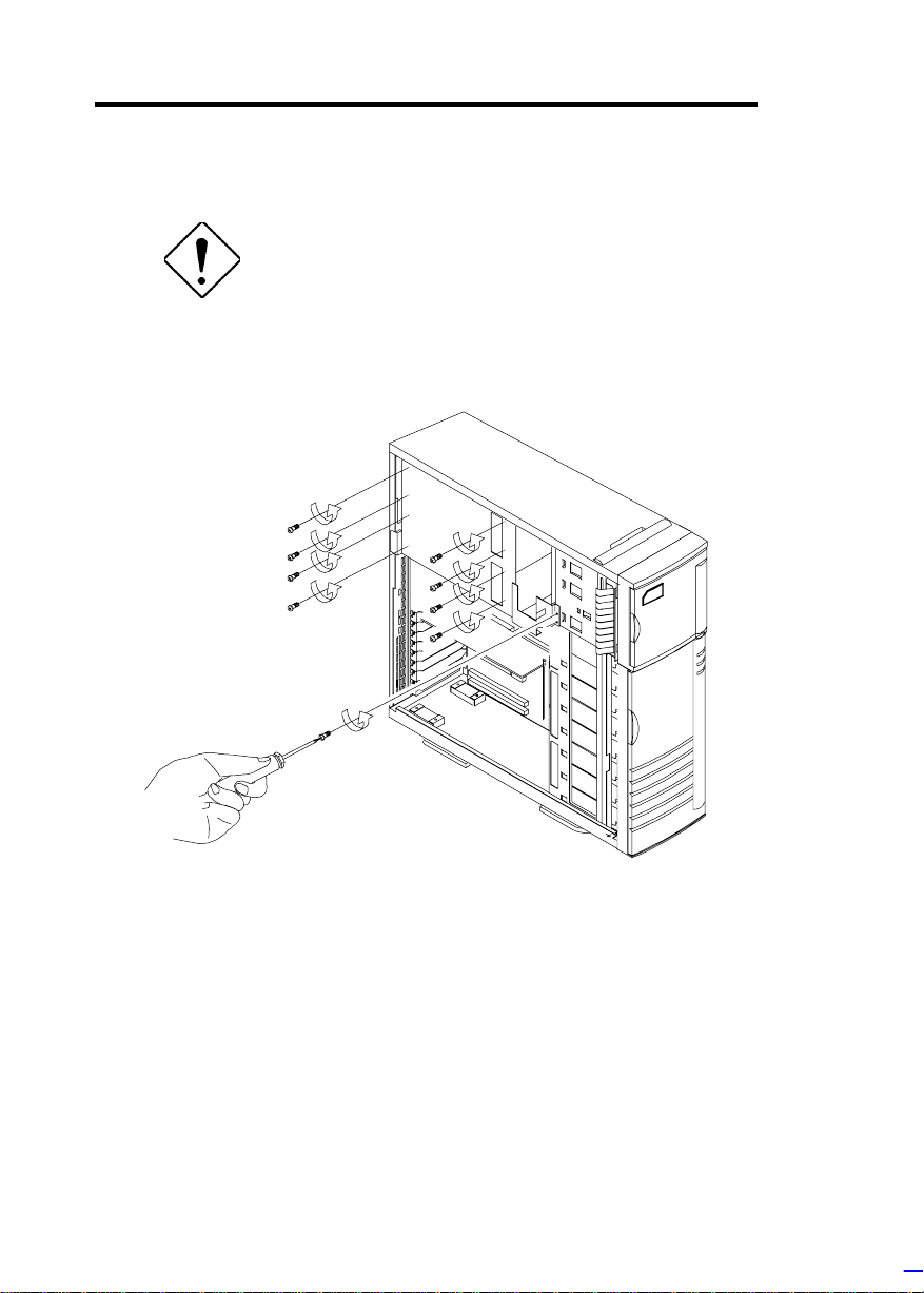
6. Remove the screws that secure the power supply holding plate.
0-16 Altos 9100B System Guid e
Page 30
7. Slide t he holding plat e to the right for about an inc h.
8. Pull out the lower part of the hol ding pl ate and unhook the upper
part fr om the housing roof.
You may need to pull the plate dow nward to
remove it easier.
System Housing 0-17
Page 31

9. Remove the screws that secure the metal cover of the upper
power supply bay to the rear panel.
10. Remove the screws that secure t he power supply m odul e. I n the
process, make sure to support t he module with your hand.
0-18 Altos 9100B System Guid e
Page 32

Installing the Power Supply Modules
1. After you have remov ed all the screws that secure the existi ng
power supply module to the lower bay, carefully move the
module t o the upper power supply bay.
2. When in place, secure t he first power supply wit h screws.
3. Get the second redundant power supply r eady .
4. Firmly hold t he power supply and align it to the lower bay.
5. When in place, secure t he second power supply wit h screws.
6. Reinstall the right door but do not close it completel y .
System Housing 0-19
Page 33

7. Connect all the power supply cables to the connectors on the
r
d
power sharing board. Make sure to connect the connectors of
power supply 1 to the three upper connectors on the power
sharing board. Connect t he connectors of power supply 2 to the
three lower connector s on the power sharing boar d.
The power connectors are foolproof and
connect only in one direct ion. If a connector
does not fit in completely, reverse its
orientation then t r y to reconnect.
Cable connections fo
power supply 1
Power sharing boar
Cable connections for
power supply 2
8. Arrange all the cables from the power sharing board and fans to
facilitate connection to the system board and di sk drives. Do not
let power cables bloc k the housing exhaust and fans.
9. Close the right door c ompletely and secure it with the screws that
you removed earlier.
10. Reconnect the fan connectors.
11. Reconnect the system board power connectors.
0-20 Altos 9100B System Guid e
Page 34

12. Reconnect the disk drives power connectors.
13. Reinstall the holding pl ate by inserting t he upper part to the rai l
on the inner side of the housing roof, then fitting in the lower
part.
14. Sli de the holding plat e to the lef t until it f its compl etely and the
screw holes match.
15. Secure the holding plate with the screws that you removed
earlier.
16. Reinstall the left door and close i t.
17. Close the lower front door and loc k the system housing.
18. Reinstall the plasti c fan cover on the rear panel .
19. Reconnect the A C power cables.
System Housing 0-21
Page 35

Installing a System Board
The housing accommodates various system board sizes. You can
rearrange the pegs on the system board pl ate t o f i t t he board that you
wish to install.
1. If you hav e not done so, open the housi ng f oll owing the steps in
the Opening t he Housi ng P anel section.
2. When ready, ali gn the system board holes to the pegs with the
external ports facing the rear of the housing.
3. Secure the board with eight screws.
0-22 Altos 9100B System Guid e
Page 36

Installing an Expansion Board
1. Remove an expansion slot bracket cover. Save the screw to
secure the expansion board.
System Housing 0-23
Page 37

2. Align an expansion board with the open slot and insert the
golden fingers into the expansion bus connector.
3. Secure the board with a screw.
0-24 Altos 9100B System Guid e
Page 38

Installing a CPU Board
If your system board does not include a CPU socket, follow these
steps to install a CP U boar d.
1. Locate the CPU board connec tor in the system boar d.
2. Insert the board i nto the connector.
Make sure that t he board is properly seated
in the connector.
3. Secure the board with a screw.
System Housing 0-25
Page 39

4. Align t he plastic support bar wit h the board edge.
5. Insert the right end of the plastic bar to the hol e on the side of
the backplane board and the left end to the hole on the rear
panel.
Left End
Right End
0-26 Altos 9100B System Guid e
Page 40

6. Insert the lef t end of t he metal support bar t abs to the holes on
the rear panel and align t he right end to the screw holes on the
side of the bac k plane board.
7. Secure the metal bar with two screws.
System Housing 0-27
Page 41

Connecting External Devices
Connecting a Monitor
0-28 Altos 9100B System Guid e
Page 42

Connecting a Keyboard
System Housing 0-29
Page 43

Connecting a Mouse
0-30 Altos 9100B System Guid e
Page 44

Connecting a Printer
System Housing 0-31
Page 45

Complete System Connections
0-32 Altos 9100B System Guid e
Page 46

Chapter 1 System Board
The system board is a dual-processor system board buil t on an ATX
baseboard that supports the Intel Penti um II CPU processor running
at 266/66 MHz, 300/66 MHz, 333/66 MHz, 350/100 MHz, 400/100
MHz, and future Int el Pent ium II proc essors. It contai ns an exclusi v e
connector f or the CPU board that carries two slots f or the P entium II
CPU modules.
The host bus interface supports a Penti um I I proc essor with 66 or 100
MHz bus frequency. It also supports synchronous DRAM (SDRAM)
DIMMs.
The system board supports PCI IDE, universal serial bus (USB)
host/hub, and enhanced power management. It also supports Ultra
DMA/33 synchronous DMA-compatibl e devices.
A 50-pin Fast SCS I (Sm all Comput er System I nterf ace) and a 68- pin
Wi de SCSI comes with the system board to connect SCSI dev ices.
Wi de SCSI supports 16-bit transfers while fast S CSI uses a 8-bit bus
that doubles the clock rate to support data rates of 20 Mb/ s.
The system board also supports the USB (Universal Serial Bus)
connector, and ot her standard f eat ures such as two UART NS16C550
serial ports, one parallel port with Enhanced Parallel Port
(EPP)/Extended Capabilities Port (ECP) features, a diskette drive
interface, and two embedded hard disk interfaces. The board also
includes a built-in 10/ 100 M b/s Intel 82557 LAN chip.
BIOS Utility 1-1
Page 47

The system board supports two optional f eatures, ASM Pro and the
remote diagnostic management (RDM), that allow better server
management . ASM Pro detects problem s in CPU therm al condi tion,
CPU working voltage detection (±12V/±5V/3.3V/1.5V), and PCI bus
utilization calculation. It also detects if the CPU fan or the chassis fan
malf uncti ons. RDM all ows executi on of t he RDM diagnosti c progr am
from a remote RDM stat ion to f ix det ected problem s or to reboot t he
syste m.
This system is fully compatible with MS-DOS V6.X, DOS/V, IBM
OS/2 Warp, Novell Netware, Novel SFT III, SCO UNIX, and Wi ndows
NT.
1-2 Altos 9100B System Guide
Page 48

Major Components
The system board has the following major components:
•
CPU board slot
•
Two ISA and five P CI bus slots
•
256-KB Flash ROM for system BIOS
•
System clock/calendar with battery backup
•
One 50-pin Fast S CS I and two 68-pin Wide SCSI interf ac es
•
One RDM inter face with two 24-pi n c onnec tors
•
IDE hard disk and di sket te drive interfaces
•
Onboard 1-MB Video DRAM
•
Power connector f or two redundant 420-watt SPS
•
Super I/O, SCSI, VGA, memory, and Advanced Server
Management (ASM) control ler chipsets
•
External ports:
• PS/2-c ompatible keyboard port (opt ional AT-key boar d por t)
• PS/2-c ompatible mouse port
• Parallel port
• Video port
• RJ-45 connector
• Universal Serial Bus (USB) connector
BIOS Utility 1-3
Page 49

System Board Layout
22
1
2
3
4
5
6
1 Mouse port
2 Keyboard port
3 Parallel port
4 Video port
5 RJ-45 connector
6 USB connector
7 LAN controller
8 PCI slots
9 ISA slots
10 Flash ROM BIOS
11 SCSI chipsets
21
19
7
8
18
17
9
12 Wide SCSI connectors
13 CPU board connectors
14 Narrow SCSI connector
15 Diskette drive connector
16 PCI chipset
17 Video controller
18 Battery
19 System Chipset FDC37C935
20 IDE connector
21 Video DRAM
22 Video DRAM upgrade sockets
16
15
14
10
13
12
12
11
1-4 Altos 9100B System Guide
Page 50

Jumpers and Connectors
Jumpers are prefixed “JP”. Connectors are
prefixed “CN”. The blackened pin of a
jumper or connector r epr es ents pin 1.
BIOS Utility 1-5
Page 51

Jumper Settings
Jumper Setting Function
Power Supply
JP1 1-2
BIOS Type
JP2 1-2
Password Security
JP3 1-2
5V Standby Source
JP4 1-2*
SCSI Channel 1
High-Byte Termination
JP6 1-2*
VGA Feature
JP7 1-2
2-3
2-3*
2-3*
2-3
2-3
2-3
*
*
420 W
200 W
Branded
Generic
Check password
Bypass password
For SPS with 5V standby
For SPS without 5V st andby
Terminator always set to ON
SCSI terminator set to ON or OFF
by software
Enabled/disabled through BIOS
Onboard VGA always disabled
Connector Functions
Connector Function
CN1 COM 1
CN2 COM 2
CN3, U1, U5 Power connectors
CN4 PS/2 mouse (above) / keyboard (below) connectors
CN5 Standby power connector for 420W standard SPS
CN6, CN7 RDM connectors
*
Default setting
1-6 Altos 9100B System Guide
Page 52

Connector Function
CN8 Power connector (connects to the system power
CN9 Standby power connector for 200W standard SPS
CN10 Pin 1 and pin 2 for power LED
CN11 Signal connector for redundant power supply
CN12 NMI signal connector
CN13 Backplane board LED connector
CN14 Printer port (above) / vi deo port ( below)
CN15 IDE connector
CN16 LAN connector
CN17 Channel 1 narrow SCSI connector
CN18 Diskette drive connector
CN19 Universal serial bus (USB) ports
CN20 CPU board connector
CN21 CPU board connector
CN22 Channel 1 wide SCSI connector
CN23 Hard disk LED connector
CN24 SMM connector
CN25 Channel 2 wide SCSI connector
CNN1 Connector f or c hass i s intrusion prevention
FAN1~ FAN3 Fan connectors
I1, I2 ISA Slots
P1-P5 PCI Slot s
button on the front panel)
(also used for 420W redundant SPS)
BIOS Utility 1-7
Page 53

ESD Precautions
Always observe the following electrostatic discharge (ESD)
precautions before installing a system component:
1. Do not remov e a component from its antistatic packaging until
you are ready to i nstall it .
2. Wear a wrist grounding strap before handling electronic
components. Wrist grounding straps are available at most
electronic component stor es.
Do not attempt the procedures described in
the following sections unless you are a
qualified technician.
1-8 Altos 9100B System Guide
Page 54

Video Memory Upgrade
Larger video memory allows you to display higher resolutions and
more colors. The system board comes with a 1-MB video memory
onboard upgradable to 2 MB .
Follow these steps to upgrade the video memory:
1. Locate the v ideo DRAM upgrade sockets labeled U36 and U37
on the system board.
2. Gently insert a v ideo chip into each of the upgrade sockets.
Make sure that the pin 1 indicator on t he chip
matches the not c hed c or ner of the socket.
Supported Video Resolutions
The onboard video control ler and MPEG decoder enable the system
to support video func tions, as well as enhance the video displ ay .
BIOS Utility 1-9
Page 55

The following table lists the video resolutions that the system
supports:
Display
Resolution
640 x 480 60 31.4 25.1
640 x 480 72 37.7 31
640 x 480 75 37.5 31.5
640 x 480 90 47.9 39.9
640 x 480 100 52.9 44.9
800 x 600
800 x 600 56 35.2 36.0
800 x 600 60 37.8 39.9
800 x 600 70 44.5 44.9
800 x 600 72 48.0 50.0
800 x 600 75 46.9 49.5
800 x 600 90 57.1 56.6
800 x 600 100 62.5 67.5
1024 x 768
1024 x 768 60 48.3 65.0
1024 x 768 70 56.4 75.0
1024 x 768 72 58.2 75.0
1024 x 768 75 60.0 78.8
1024 x 768 90 76.2 100
1024 x 768 100 79.0 110
1152 x 864
1152 x 864
1152 x 864 60 54.9 80.0
1152 x 864 70 66.1 100
1152 x 864 75 75.1 110
1280 x 1024
1280 x 1024
Refresh
Rate
int.
48
int.
43
int.
43
int.
47
int.
43
int.
47
Horizontal
Frequency (KHz)
33.8 36.0
35.5 44.9
45.8 65.0
44.9 65.0
50.0 80.0
50.0 80.0
Pixel Clock
(MHz)
1-10 Altos 9100B System Guide
Page 56

Display
Resolution
1280 x 1024 60 64 110
1280 x 1024 70 74.6 126
1280 x 1024 74 77.9 135
1280 x 1024 75 80 135
Refresh
Rate
Horizontal
Frequency (KHz)
Pixel Clock
(MHz)
int.
interlaced
BIOS Utility 1-11
Page 57

Installing Expansion Cards
Installing a PCI Card
To install PCI cards:
1. Locate the PCI sl ot(s) on the mai nboar d.
2. Remov e the bracket on the housing opposite t o the empty PCI
slot .
3. Insert a PCI card into the slot. Make sure that the card is
properly seated.
4. Secure the card t o the housing with a screw.
When you turn on the system, BIOS automatically detects and
assigns resources to the PCI devices.
Installing an ISA Card
Both PnP and non-PnP ISA cards require specific IRQs. When
install ing ISA cards, make sure that the I RQs required by t hese cards
are not previously assigned to PCI devices to avoid resource
conflicts.
Follow these steps when installi ng ISA cards:
1-12 Altos 9100B System Guide
Page 58

1. Remove all PnP c ar ds i nstalled in t he system, if any.
2. Install non-PnP ISA cards.
3. Turn on the system.
4. Use Wi ndows 95 or ICU to manually assign t he appropriate IRQs
to the cards. This ensures that BIOS will not use the resources
assigned to the non-PnP IS A c ar ds.
BIOS detects and c onfigures only PnP cards.
5. Turn off the system.
6. Locate the expansion slots and install the PnP ISA and PCI
cards.
7. Turn on the system. This time PnP BIOS automatically
configures the PnP ISA and PCI cards with the available
resources.
BIOS Utility 1-13
Page 59

ASM Pro
ASM Pro is a server m anagement t ool based on the Simpl e Network
Management Protocol (SNMP). It detects server problem s related to
the CPU thermal condition, 5V/3.3V/1.5V detection, or PCI bus
utilization calculation.
This feature is designed primarily for server supervisors and
management i nf orm at ion system (MIS ) personnel t o hel p t hem detect
errors or potential trouble spots in their network servers through a
single management stati on.
ASM Pro consists of two major parts:
•
ASM-Station - a Windows-based monitoring station that
communicates with the ASM-Agents.
•
ASM-Agent(s) - the individual servers managed by the
ASM-Station.
Refer to the ASM Pro user’s manual for more information.
1-14 Altos 9100B System Guide
Page 60

Remote Diagnostic Management
Remote Diagnostic Management (RDM) is a network management
tool that utilizes modems and telephone lines to control a host of
servers from a remote station. It moni tors and analyzes the server
condition, updates the BIOS settings if necessary, or reboots the
server in the event of failure and quickly returns it to normal
operation. This capability to execute the RDM program from a
remote sit e bridges the di stance barri er in f ix ing serv er pr oblem s and
reduces wasted time due to system fai lure.
Installing an RDM Module
The system board comes with connectors CN6 and CN7 to
accommodate the RDM m odule.
Follow these steps to install the RDM module and connect the cable:
1. See the Jumpers and Connectors section f or the locati on of the
RDM connectors.
2. Gently i nsert the RDM m odule into CN6 and CN7. The m odule
fits only in one dir ec tion. Do not force it into to the connec tors.
CN7
CN6
Refer to the RDM User’s Guide for detailed instructions on RDM
installation.
BIOS Utility 1-15
Page 61

Error Messages
Do not continue usi ng the computer if you receiv e an error m essage
of any type. Note the message and take corrective action. This
section explains the different types of error messages and
corresponding corrective measures.
There are two general t y pes of error messages:
•
Software
•
System
Software Error Messages
Software error messages are returned by your operating system or
application. These messages typically occur after you boot the
operating system or when you run your appl ications. If you receiv e
this type of message, consult your application or operating system
manual for help.
System Error Messages
A system error message indicates a problem with the c omputer itself .
A message of this type normally appears during the power-on selftest, bef or e the operating system pr ompt appears.
Message Acti on
CMOS Battery Error Replace the RTC chip or
contact your dealer.
CMOS Checksum Error Check the RTC chip and the
necessary jumper. If the
battery is still good, run
Setup.
Display Card Mismat ch Run Setup.
1-16 Altos 9100B System Guide
Page 62

Message Action
Diskett e Drive Controller
Error or Not Installed
Diskette Drive Error Diskette may be defective. If
Diskette Drive A Type
Mismatch
Diskette Drive B Type
Mismatch
Equipment Configuration
Error
Hard disk Controller Error Run Setup.
Hard disk 0 Error Check all cable connections.
Hard disk 1 Error Check all cable connections.
Keyboard Error or No
Keyboard Connected
Keyboard Interface Error Replace the keyboard or
Memory Error at:
MMMM:SSSS:OOO
(W:XXXX, R:YYYY)
where:
M: MB, S: Segment,
O: Offset, X/Y: write/read
pattern
Memor y Size Mismatc h
CPU Clock Mismatch
Check and connect the
control cable to the diskette
controller.
not, replace the diskette drive.
Run Setup and select the
proper drive type.
Run Setup and select the
proper drive type.
Modify the memory
configurati on t o agr ee with
one of the options in the
Memory Configurati ons
section.
Replace hard disk.
Replace hard disk.
Check and connect the
keyboard to the system unit.
contact your dealer.
Check installed DIMMs.
Contact your dealer.
Run Setup. Check if the
values shown in the memory
parameters are correct. If
correct, exit Setup and reboot
the system. If the error
message reappears, seek
technical assistance.
BIOS Utility 1-17
Page 63

Message Acti on
Onboard Serial Port 1
Conflict
Onboard Serial Port 2
Conflict
Onboard Parallel Port
Conflict
Pointing Device Error Check and connect pointing
Pointing Device Interface
Error
Press F1 key to continue or
Ctrl-Alt-Esc for Setup
Real Time Clock Error Check the RTC chip. If it is
CPU BIOS Code Mismatch Contact your dealer.
Run Setup and disable the
port.
Run Setup and disable the
port.
Run Setup and disable the
port.
device.
Replace the pointing device or
contact your dealer.
Press
press
enter Setup.
still good, run Setup. If not,
replace the RTC chip.
or simul at aneously
+ + to
Correcting Error Conditions
As a general rule, if an error m essage says "Press F1 t o conti nue," it
is caused by a confi guration probl em, which c an be easily corrected.
An equipment malfunction is more li k ely to cause a fatal error, i.e., an
error that causes com plete system failure.
Here are some corrective measures for err or c onditions:
1. Run Setup. You m ust know the correct confi guration v alues for
your system before you enter Setup, which is why you should
write them down when the system is correctly configured. An
incorrect configuration is a major cause of power-on error
messages, especially for a new system.
2. Remov e the system unit c over. Check t hat the jum pers on the
system board and any ex pansi on boar ds are set cor r ec tly.
1-18 Altos 9100B System Guide
Page 64

3. If you cannot access a new disk, it m ay be because your disk is
not properly formatted. Format the disk first using the FDISK
and FORMAT c ommands.
4. Check that al l connectors and boards are securely plugged in.
If you go t hrough t he correc ti ve steps above and still receive an error
message, the cause may be an equipment malf unc tion.
If you are sure that your configuration values are correct and your
battery is in good condition, the problem may lie in a damaged or
defective c hip.
In either c ase, c ontact an authori z ed service c enter for assistance.
BIOS Utility 1-19
Page 65

Chapter 2 CPU Board
2
e
s
The CPU board carries two sockets to support a powerf ul dual-CPU
configuration. The sockets accommodate the new Intel Pentium II
CPU running at 266/66, 300/66, 333/66, 350/100, 400/100, or f uture
Intel Pentium I I processors and higher.
The board comes with four DRAM banks composed of f our 168-pin
dual-inline memory module (DIMM) sockets that accommodate
Synchronous DRAM (SDRAM) DIMMs. The system’s CPU board
supports multiple-bit error detection and single-bit error correction
through the ECC/par ity f eature.
CPU Board Layout
CPU Voltag
Regulator
Pentiu m II CPU Socket
Pentiu m II CPU Socket 1
System Chip set
DIMM Sockets
CPU Board 2-1
Page 66

CPU Board Jumpers and Connectors
Jumpers are prefixed “JP”. Connectors are
prefixed “CN”. The blackened pin of a
jumper represents pin 1.
Jumper Settings
JP1 Settings
1-2-3 4-5-6 7-8-9 10-11-12 CPU Core/Bus Freq.
1-2 Closed 4-5 Closed 7-8 Closed 10-11 Closed 1/2
1-2 Closed 4-5 Closed 8-9 Closed 10-11 Closed 1/3
1-2 Closed 4-5 Closed 7-8 Closed 11-12 Closed 1/4
1-2 Closed 4-5 Closed 8-9 Closed 11-12 Closed 1/5
1-2 Closed 5-6 Closed 7-8 Closed 10-11 Closed 2/5
1-2 Closed 5-6 Closed 8-9 Closed 10-11 Closed 2/7
1-2 Closed 5-6 Closed 7-8 Closed 11-12 Closed 2/9
1-2 Closed 5-6 Closed 8-9 Closed 11-12 Closed 2/11
2-2 Altos 9100B System Guide
Page 67

Connector Functions
Connector Function
CN1 CPU 2 Fan connector
CN2 CPU 2 Thermal Detection connector
CN3 CPU 1 Fan connector
CN4 CPU 1 Thermal Detection connector
CPU Board 2-3
Page 68

Memory Upg rade
The CPU board comes with four 168-pi n sockets, labeled DIMM1 to
DIMM4, that accommodate single-density and double-density,
unbuffered or registered SDRA M DIMMs.
The SDRAM DIMMs should work under 3.3 volts, 5 volts memory
devices are not supported. Memory timing setting of 66 MHz are
defined under unbuffered DIMM specifications while 100 MHz are
defined under Intel PC-100 SDRAM and PC registered DIMM
specifications.
Do not use both 66 MHz (unbuffered) and
100 MHz (registered) SDRAM toget her. This
might cause your system to malfunction.
The sockets support SDRAM DIMMs for a total of 1024-MB
(unbuff ered) system memory using 128-MB DIMMs.
Memory Configurations
Bank 1 Bank 2 Bank 3 Bank 4 Total
Memory
32 MB 32 MB
32 MB 32 MB 64 MB
32 MB 32 MB 32 MB 96 MB
32 MB 32 MB 32 MB 32 MB 128 MB
64 MB 64 MB
64 MB 64 MB 128 MB
64 MB 64 MB 64 MB 192 MB
64 MB 64 MB 64 MB 64 MB 256 MB
128 MB 128 MB
128 MB 128 MB 256 MB
2-4 Altos 9100B System Guide
Page 69

Bank 1 Bank 2 Bank 3 Bank 4 Total
Memory
128 MB 128 MB 128 MB 384 MB
128 MB 128 MB 128 MB 128 MB 512 MB
256 MB 256 MB
256 MB 256 MB 512 MB
256 MB 256 MB 256 MB 768 MB
256 MB 256 MB 256 MB 256 MB 1024 MB
The above configurations are only some of
the available memory combinations. When
upgrading memory, simply install DIMMs into
any of the empty s oc k ets.
Installing a DIMM
To install a DIMM, al ign it with the socket and press it down unti l the
holding clips secure the DIMM in place.
The DIMM socket is slotted to ensur e proper
installation. If you slip in a DIMM but it does
not completely fit, you may have inserted it
the wrong way. Reverse the orientation of
the DIMM.
CPU Board 2-5
Page 70

Removing a DIMM
To remove a DIMM, press the holding clips on both sides of the
socket outward to release the DIMM.
Place your forefingers on the top of the
DIMM before you press the holding clips to
gently disengage the DIMM f r om the socket.
2-6 Altos 9100B System Guide
Page 71

Reconfiguring the System
You must enter Setup after installing or removing DIMMs to
reconfigure the system.
Follow these steps to reconfigure the system:
1. Turn the system on. A memory error message appears,
indicat ing t hat t he tot al m em ory does not m atc h t he v al ue stored
in CMOS.
2. Simultaneously Press
warning message appears indicating an incorrect memory
configuration.
3. Press
The system boots with t he new m emory configurati on.
twice to ex it and reboot the system.
+ + to enter Setup. A
CPU Board 2-7
Page 72

Installing a Pentium II Processor
You must install t he heatsink and fan before
you install the processor module into the
socket on the CPU boar d.
The Pentium II processor module comes with holes on one side to
hold the cl ips of the heatsink and f an. The upper set of holes (near
the latches) on t he processor are wider and should m atch the wider
ends of the clips on the heatsink. The lower set of hol es are smaller
and should match the narrow ends of the heatsink c lips.
Wide Clip Ends
Wide Holes
Narrow Holes
Installing the Processor Heatsink and Fan
Follow these steps when installing the heatsink and fan into the
Pentium II processor module:
2-8 Altos 9100B System Guide
Page 73

1. Remove the thermal tape protec tor at the back of the heatsink.
2. Insert the wide cl ip ends into the wide hol es on the processor and
the narrow clip ends i nto the narrow holes.
CPU Board 2-9
Page 74

3. Use a screwdriver t o pr ess and lock in the wide end of a clip first.
Then without lifting the screwdriv er, point it downward to press
and lock the narr ow end of the cli p.
4. Repeat step 3 to lock the other clip.
2-10 Altos 9100B System Guide
Page 75

Installing the Processor Module
Follow these steps to instal l t he Penti um II processor modul e into t he
socket on the CPU board.
1. Place the retenti on mechanism ov er the processor socket on t he
CPU board. Secure it with the screws that came with the
package.
2. With the processor module golden fingers pointing downward,
align the processor to the posts of t he retent ion m echanism t hen
lower it down.
The golden fingers of the Pentium II module
are slotted such that it only fits in one
direction. Make sure that module groove
matches the one on t he pr oc es s or s oc k et.
CPU Board 2-11
Page 76

3. Press down the processor module until the golden fingers
completely fit into the socket.
4. Press the latches on the sides to lock the processor module i nto
place.
5. Locate the f an connectors on the system boar d and connect the
fan cabl es.
2-12 Altos 9100B System Guide
Page 77

Uninstalling the Processor
Removing the Processor from the Slot
Follow these steps to rem ove the Pent ium II pr ocessor module from
the slot.
1. Detach the fan cables from the connector s on the system board.
2. Unlock the latches that secure the proc essor m odule.
3. Firmly hold t he pr oc essor m odule and pull it out of the socket.
CPU Board 2-13
Page 78

Removing the Processor Heatsink and Fan
Follow these steps to remove t he pr oc essor heatsink and fan:
1. Insert a flat-t ype screwdriver to one of t he wide clip ends of t he
processor heatsink and fan.
2. Push the clip end to release cli p from the processor.
3. Repeat steps 1 and 2 to release the other c lip.
2-14 Altos 9100B System Guide
Page 79

4. When you have released both clips, take off the processor
heatsink and f an.
CPU Board 2-15
Page 80

Installing the Termination Board
When you use only one slot on the CPU board, you must install a
termination board i nto the empty sl ot.
Follow these steps to install the ter mination board:
1. Position t he termination board over the empt y sl ot.
2. Careful ly insert the golden f ingers of the term ination board into
the slot until the board fits com pletely.
Do not forget t o install the termination boar d
if you only have one process or .
2-16 Altos 9100B System Guide
Page 81

CPU Board Installation
After setting the jum pers and installing m emory m odules and CPUs,
install the CPU board into t he CP U boar d sl ot on the system board.
Follow these steps to install the CPU board:
1. Position the CPU board ov er the slot on the system board such
that the component side (CPU side) faces upward.
2. Gently insert the golden fingers of the board into the slot.
Make sure that the CPU board is properly
seated in the slot.
CPU Board 2-17
Page 82

Chapter 3 BIOS Utility
The BIOS Utility allows you to view your system’s configuration
settings.
Most systems are already configured by the manufacturer or the
dealer. There is no need to run Setup when starting the computer
unless you get a Run Setup m essage.
The Setup program loads configuration val ues into the bat t ery-backed
nonvolatile memory called CMOS RAM. This memory area is not
part of the system RAM.
If you repeatedly receive Run Setup
messages, the battery may be bad. In this
case, the system cannot retain configuration
values in CMOS. Ask a qualified technician
for assistance.
BIOS Utility 3-1
Page 83

Entering Setup
To enter Setup, simultaneously press the key combination
+ + .
You must press + +
system is booting. This key combination
does not work dur ing any other time.
The BIOS Utility main menu then appears:
BIOS Utility
System Information
Product Information
Disk Drives
Power Management
Startup Configuration
Advanced Configuration
System Security
Remote Diagnostic Configuration
↑↓←→ = Move highlight bar, ↵
Date and Time
Load Default Settings
Abort Settings Change
= Select, Esc = Exit
while the
The parameters on t he screens s how def ault
values. These values may not be the same
as those in your system.
3-2 Altos 9100B System Guide
Page 84

System Information
The fol lowing screen appears if you select System Inform ation from
the mai n menu:
System Information Page 1/2
Processor.......................Pentium II
Processor Speed.................xxx MHz
Bus Frequency...................xxx MHz
Internal Cache..................xx KB, Enabled
External Cache..................xxx KB, Enabled
Floppy Drive A..................x.xx MB, x.x-inch
Floppy Drive B..................None
IDE Primary
IDE Primary
Total Memory....................xx MB
1st Bank......................SDRAM
2nd Bank......................SDRAM
3rd Bank......................SDRAM
4th Bank......................SDRAM
PgDn/PgUp = Move Screen, Esc = Back to Main Menu
The System I nformat ion menu shows the current basic configurati on
of your system.
Channel Master ......Hard Disk
Channel Slave .......None
The comm and line at the bottom of the m enu tell s you how to m ove
from one screen to another and retur n to the mai n menu.
Press
to move to the next page or to return to the previ ous
page.
Press
to return to the main menu.
BIOS Utility 3-3
Page 85

The following screen shows page 2 of the System Information m enu.
System Information Page 2/2
Serial Port 1 ..................... Disabled
Serial Port 2 ..................... 2F8h, IRQ 3
Parallel Port .................... 378h, IRQ 7
Pointing Device ................... Installed
Memory Parity Mode ................ Disabled
Onboard USB ....................... Disabled
PgDn/PgUp = Move Screen, Esc = Back to Main Menu
The sections that foll ow ex plain each parameter.
The parameters in the System Information
screens show default settings. These
settings are non-configurable from these
screens. Select other configuration options
from the BIOS Utility main menu to change
the settings.
Processor
The Processor parameter specifies the type of processor currently
install ed in your system. The system is designed t o support the Intel
Pentium II CPU.
3-4 Altos 9100B System Guide
Page 86

Processor Speed
The Processor Speed parameter specifies the speed of the CPU
currently install ed in your system. T he system supports Intel Pent ium
II CPUs running at 266/66 MHz, 300/66 MHz, 333/66 MHz, 350/100
MHz, 400/100 MHz, and future Intel Pentium II pr oc essors.
Bus Frequency
The Bus Frequency parameter specifies the system external clock.
The bus frequency c an be either 66 or 100 MHz.
Internal Cache
This parameter specifies the first-level or the internal memory size
(i.e., the memory i ntegrated int o the CPU), and whether i t is enabled
or disabled. See the Memory Configuration section for more
information.
External Cache
This parameter specifies the second-level cache memory size
currently supported by the system, and whether it is enabled or
disabled. See t he M emory Conf iguration section for more inf or mation.
Floppy Drive A
This parameter specif i es the t ype of dri ve designated as Fl oppy Dri ve
A.
Floppy Drive B
This parameter specifies the system’s current floppy dri ve B settings.
BIOS Utility 3-5
Page 87

IDE Primary Channel Master
This parameter specif ies the current confi guration of the I DE device
connected to the master port of the primary IDE channel .
IDE Primary Channel Slave
This parameter specif ies the current confi guration of the I DE device
connected to the sl ave port of the pri mary IDE channel.
Total Memory
This parameter specifies the total system memor y . The memory size
is automat ically detect ed by BIOS during the PO ST (Power-On Self
Test). If you install additional memory, the system automatically
adjusts this param eter to display the new memory siz e.
1st Bank/2nd Bank/3rd Bank/4t h Bank
This parameter indicates the type of DRAM installed in the DIMM
sockets. The
For the location of the DIMM sockets, refer to the System Board
Layout.
setting indic ates that there i s no DRAM installed.
None
Serial Port 1
This parameter indicates the serial port 1 addr ess and IRQ setting.
Serial Port 2
This parameter indicates the serial port 2 addr ess and IRQ setting.
Parallel Port
This parameter indicates the parallel port address and IRQ setting.
3-6 Altos 9100B System Guide
Page 88

Pointing Device
The BIOS utility automatically detects if there is a mouse connected
to the system. If there is, this parameter displays the
setting. Otherwise, it is set to
None
.
Installed
Memory Parity Mode
This paramet er indicates the setti ng of the mem ory parity mode. I t
may be set to
Disabled
, ECC, EC, or E CC- HS .
Onboard USB
This parameter specifies whether the onboard USB controller is
enabled or not.
BIOS Utility 3-7
Page 89

Product Information
The Product Infor mation contains general data about t he system . It
includes the product name, serial number, BIOS v ersion, etc. This
information is necessary for troubleshooting and may be required
when asking for technical support.
The following screen shows the Product Information item s:
Product Information Page 1/1
Product Name........................... xxxxxxxxx
System S/N............................. xxxxxxxxx
Main Board ID.......................... xxxxxxxxx
Main Board S/N......................... xxxxxxxxx
System BIOS Version.................... vx.xx
System BIOS ID......................... xxx.xx xxx-xx
BIOS Release Date...................... xx/xx/xx
Esc = Back to Main Menu
Product Name
This parameter specifies the official name of the system.
System S/N
This parameter specifies the system’s serial number.
3-8 Altos 9100B System Guide
Page 90

Main Board ID
This parameter specifies the system board’s identific ation number.
Main Board S/N
This parameter specifies the system board’s serial number.
System BIOS Version
This parameter specifies the version of the BIOS utility.
System BIOS ID
This parameter specifies the identi fication number of the BIOS ut ility.
BIOS Release Date
This parameter specifies the official date the BIOS version was
released.
BIOS Utility 3-9
Page 91

Disk Drives
The Disk Driv es menu lets you confi gure the system hard disk and
disk drive settings. If your hard disk supports the enhanced IDE
features, y ou may set the functions using this menu.
The following screen shows the Disk Drives parameters and their
default settings:
Disk Drives Page 1/1
Floppy Drive A ........... [xx-MB, xx-inch]
Floppy Drive B ........... [xx-MB, xx-inch]
IDE Primary Channel Master
IDE Primary Channel Slave
↑↓ = Move Highlight Bar, → ← = Change Setting, F1 = Help
The triangle mark that precedes an item
within a menu indicates that there is a
detailed menu for that particular it em. Select
the item to display the menu.
3-10 Altos 9100B System Guide
Page 92

From t he Disk Driv es screen, sel ect the I DE Pri mary Channel Master
or IDE Primary Channel Slave items to display their respective
menus.
Selecti ng the I DE Pr i m ary Channel Master i t em displ ays the f ol l owing
menu:
IDE Primary Channel Master Page 1/1
Type .................................. [Auto]
Cylinder........................... [ ]
Head............................... [ ]
Sector............................. [ ]
Size............................... [ ] MB
Hard Disk Block Mode ................. [Disabled]
Advanced PIO Mode .................... [Auto]
Hard Disk Size > 504MB ............... [Disabled]
Hard Disk 32 Bit Access .............. [Disabled]
CD-ROM Drive DMA Mode ................ [Disabled]
↑↓ = Move Highlight Bar, → ← = Change Setting, F1 = Help
The parameters for the IDE Primary Channel Slave menu are the
same as in the above screen.
BIOS Utility 3-11
Page 93

Floppy Drives
To confi gure t he f i rst f l oppy dr ive (dri ve A), highl ight the F l oppy Dri ve
A parameter . Press
appropriate value.
Possible settings for the Fl oppy Dr ive par ameters are:
•
[ None ]
•
[360 KB, 5.25-inch]
•
[1.2 MB, 5.25-inch]
•
[720 KB, 3.5-inch]
•
[1.44 MB, 3.5-inch]
•
[2.88 MB, 3.5-inch]
or key to view the opti ons, then sel ect t he
Follow the same procedure to conf i gure f l oppy dr ive B. Choose
if y ou do not have a second floppy dri ve.
None
IDE Drives
There are two IDE drive option items under the Disk Drives menu.
Select the IDE Prim ary Channel Master if you want to configure an
IDE device set as master. Select the IDE Primary Channel Slave
item if you want to c onfigure an I DE devic e set as slave.
To configure an IDE device designat ed as master:
1. Select t he IDE Primary Channel option to display i ts menu.
2. Highli ght the paramet er T ype, t hen press
IDE drive types with their respective values for cylinder, head,
sector, and size.
or to display the
3-12 Altos 9100B System Guide
Page 94

You may do any of the f ollowing:
• Select the type that c or r esponds to your IDE hard disk drive.
• If you do not know the ex act type of your IDE device, sel ect
the
the installed IDE drive type.
option to let the BIOS utility automatically detect
Auto
• You m ay sav e the v al ues under the opti on
tim e you boot the system , the BI OS utility does not hav e to
auto-configure your IDE drive as it detects the saved disk
informati on during POST (Power-On Self Test).
User
. The next
We recommend that you copy the IDE disk
drive values and keep them in a safe place in
case you have to reconf igure the disk in the
future.
• If you have installed an IDE hard disk that was previ ously
formatted but does not use the disk native parameters or
structure, i.e., the di sk may be f ormatted according to the
user-specified number of cylinders, heads, and sectors,
select the
information.
•
If t her e is no devi c e c onnec ted, choose
To configure an IDE device designat ed as slave:
1. Select t he IDE Primary Channel option to display i ts menu.
2. Highli ght the paramet er T ype, t hen press
IDE drive types with their respective values for cylinder, head,
sector, and size. Ref er to the above procedure f or conf i guring a
master device.
option. Then enter the appropriate drive
User
.
None
or to display the
BIOS Utility 3-13
Page 95

Hard Disk Block M ode
This func tion enhances di sk perform ance dependi ng on the har d disk
in use. If you set this parameter to
automatically detects if the installed hard disk drive supports the
Block Mode function. If supported, it allows data transfer in block
(multi ple sectors) at a rate of 256 byt es per cycle. To disregard the
feature, change the setting to
Advanced PIO Mode
Disabled
.
, the BIOS utility
Auto
When set to
install ed hard disk supports the function. If supported, it allows for
faster data recovery and read/write timing that reduces hard disk
activity time. This results in better hard disk performance. To
disregard the feature, change the setting to
Hard Disk Size > 504 MB
When set to
install ed hard disk supports the function. If supported, i t al l ows you to
use a hard disk with a capacity of more than 504 MB. This is made
possible through the Logical Block Address (LBA) mode translation.
However, this enhanced IDE feature works only under DOS and
Windows 3.x, Windows 95 environments. Other operating systems
require this parameter to be set to
Hard Disk 32-bi t Access
Enabling this parameter improves system performance by allowing
the use of the 32-bi t hard disk access. This enhanced IDE f eature
works only under DOS, Windows 3.x, Windows 95, and Novell
NetW are. If your soft ware or hard di sk does not support thi s f uncti on,
set this parameter to
, the BIOS utility automatically detects if the
Auto
Disabled
, the BIOS utility automatically detects if the
Auto
.
Disabled
Disabled
.
.
3-14 Altos 9100B System Guide
Page 96

CD-ROM Drive DMA Mod e
This parameter allows you to enable or disable the CD-ROM driv e
DMA mode. S et this parameter to
for the CD- ROM dri v e. Thi s impr ov es the system perf orm ance since
it all ows direct memory access to the CD-ROM. To deactiv ate the
function, set the parameter to
Enabled
Disabled
to enable the DMA m ode
.
BIOS Utility 3-15
Page 97

Power Management
The Power Management m enu lets you confi gure the system power
management features.
The fol lowing screen shows the Power Management param eters with
their default settings:
Power Management Page 1/1
Power Management Mode ................. [Disabled]
IDE Hard Disk Standby Timer ........ [---]
System Sleep Timer ................. [---]
Stop CPU Clock in Sleep State ... [---]
↑↓ = Move Highlight Bar, → ← = Change Setting, F1 = Help
Power Management Mode
This parameter all ows you to reduce power consumption. When t his
parameter is set to
Enabled
system timers. Setting to
, you can configure the IDE hard disk and
Disabled
deactivates the power
management feature and all the timers.
IDE Hard Disk St andby T imer
This parameter allows the hard disk to enter standby mode after
inacti vity of 1 to 15 mi nutes, depending on your setting. When you
access the hard disk again, allow 3 to 5 seconds (depending on the
hard disk) f or the disk to ret urn to normal speed. Set thi s parameter
to
if y our har d disk does not support this f unc tion.
OFF
3-16 Altos 9100B System Guide
Page 98

System Sleep Timer
This paramet er sets the system to the l owest power-saving m ode. It
automatically enters into the sleep or the suspend mode after a
specifi ed period of inactiv ity. Any keyboard or m ouse action, or any
modem detected resumes system operation.
Stop CPU Clock in Sleep State
If you want t o stop the CPU clock when the system enters the sleep or
suspend mode, set this parameter to
. If not, then select No.
Yes
BIOS Utility 3-17
Page 99

Startup Configuration
The Startup Configurat ion al l ows you to specif y your pr ef erred sett ing
for bootup.
The fol lowing screen appears if you select the Startup Conf iguration
option from the main menu:
Startup Configuration Page 1/1
Fast POST Mode ........................ [Auto ]
Silent Boot ........................... [Enabled ]
Num Lock After Boot ................... [Enabled ]
Memory Test ........................... [Disabled]
Initialize SCSI Before IDE ............ [Disabled]
System Boot Drive ..................... [Drive A Then C]
Boot from IDE CD-ROM .................. [Disabled]
↑↓ = Move Highlight Bar, → ← = Change Setting, F1 = Help
Fast POST Mode
This parameter allows the system to boot faster by skipping some
POST (Power-O n S elf Test) r outines. The default setting is
3-18 Altos 9100B System Guide
Auto
.
Page 100

Silent Boot
This paramet er enables or disables the Silent Boot func tion. W hen
set to
identification logo during POST and while booting, after which the
screen displays the operati ng system prompt (such as DOS) or logo
(such as Windows 95). If any error occurred while booting, the
system autom atically switches to the text mode.
Enabled
, BIOS is in graphical mode and displays only an
Even if your setting is
while booting by pressing
activation of the keyboard.
When set t o
you see the system initialization det ails on the screen.
Disabled
Enabled
, BIOS is in the c onv entional tex t m ode where
, you may also switch to the tex t mode
after y ou hear a beep that indi cates the
Num Lock After Boot
This parameter allows you to activate the Num Lock function upon
booting. T he default setting is
Enabled
.
Memory Test
When set t o
RAM test during the POST routine. When set to
system detects onl y the memory size and bypasses the test routine.
The default setting is
Enabled
, this param eter al lows the system to per form a
, the
Disabled
Disabled
.
Initialize SCSI Before IDE
Enabling t his parameter all ows SCSI devic es installed i n the system
to be initi alized bef ore IDE dev ices. Y ou may enable t his parameter
if y ou hav e a SCSI boot dr iv e. W hen t his param eter is di sabled, the
IDE drives are normally initialized first during POS T.
BIOS Utility 3-19
 Loading...