

Page 1

& K DSWHU
System Board
1.1 Features
The M9N is a dual-processor system board that supports the Intel
Pentium II CPU. It contains an exclusive connector for the CPU board
that carries two slots for the Pentium II CPU modules.
This high-perform ance 64-bit system board utilizes both the ISA and
the PCI local bus architecture. Two ISA and five PCI bus slots reside
on the board to allow installation of either master or slave devices.
A 50-pin Fast SCSI-II interface and two 68-pin W ide SCSI interfaces
come with the system board to connect SCSI devices. External I/O
interfaces include a parallel port and a video port, RJ-45 and USB
connectors, and keyboard and mouse ports.
The system board supports two optional features, the ASM Pro and
the remote diagnostic management (RDM), that allow better server
management. The ASM Pro detects problems in CPU thermal
condition, CPU working voltage detection (±12V/±5V/3.3V/1.5V), and
PCI bus utilization calculation. It also detects if the CPU fan or the
chassis fan malfunctions. The RDM allows execution of the RDM
diagnostic program from a remote RDM station to fix detected
problems or to reboot the system.
System Board 1-1
Page 2

1.2 Major Components
The system board has the following major components:
CPU board slot
•
Two ISA and five PCI bus slots (one PCI slot may include an
•
optional RAID port)
256-KB Flash ROM for system BIOS
•
System clock/calendar with battery backup
•
50-pin Fast SCSI-II and two 68-pin Wide SCSI interfaces
•
Two 24-pin RDM interfaces
•
IDE hard disk and diskette drive interfaces
•
Onboard VRAM and VRAM sockets for video memory upgrade
•
Power connector for both standard 420-watt SPS and redundant
•
420-watt SPS
Super I/O, SCSI, VGA, memory, and Advanced Server
•
Management (ASM) controller chipsets
External ports:
•
PS/2-compatible keyboard port (optional AT-keyboard port)
•
PS/2-compatible mouse port
•
Parallel port
•
Video port
•
RJ-45 connector
•
Universal Serial Bus (USB) connector
•
1-2 User’s Guide
Page 3
1.3 Layout
3
5
278
9
918
2
4
6
0
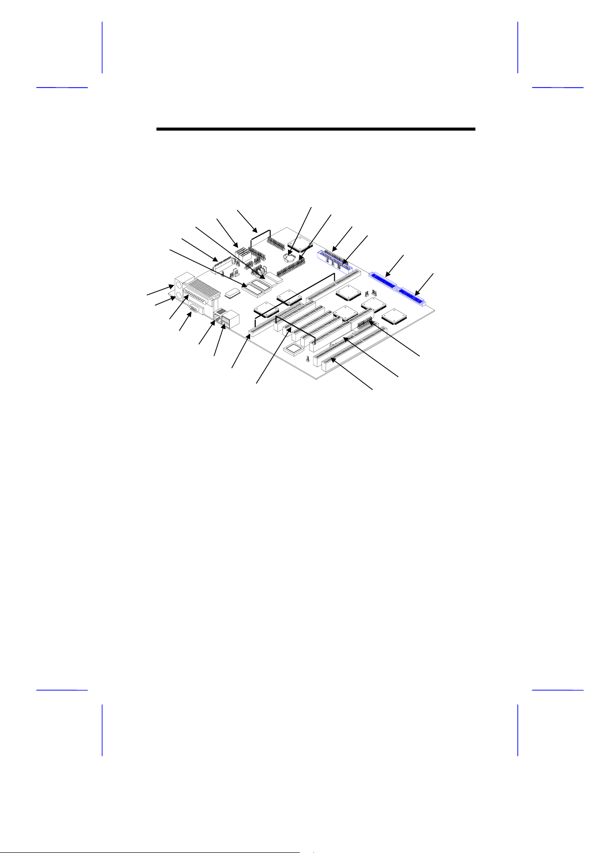
Figure 1-1 shows the system board components.
17
1
2
21
2
1
16
15
14
13
12
11
10
1 Keyboard port
2 Mouse port
3 Parallel port
4 Video port
5 RJ-45 connector
6 USB connector
7 CPU board slot
8 PCI slots
9 ISA slots
10 Flash ROM BIOS
11 RAID port (optional)
12 Wide SCSI connector 2
13 Wide SCSI connector 1
14 Narrow SCSI connector
15 Diskette drive connector
16 EIDE connector
17 Battery
18 RDM connectors
19 Power connectors
20 Video RAM
21 Power connector
22 Video RAM upgrade sockets
Figure 1-1 System Board Layout
System Board 1-3
Page 4
1.4 Jumpers and Connectors
1.4.1 Jumper and Connector Locations
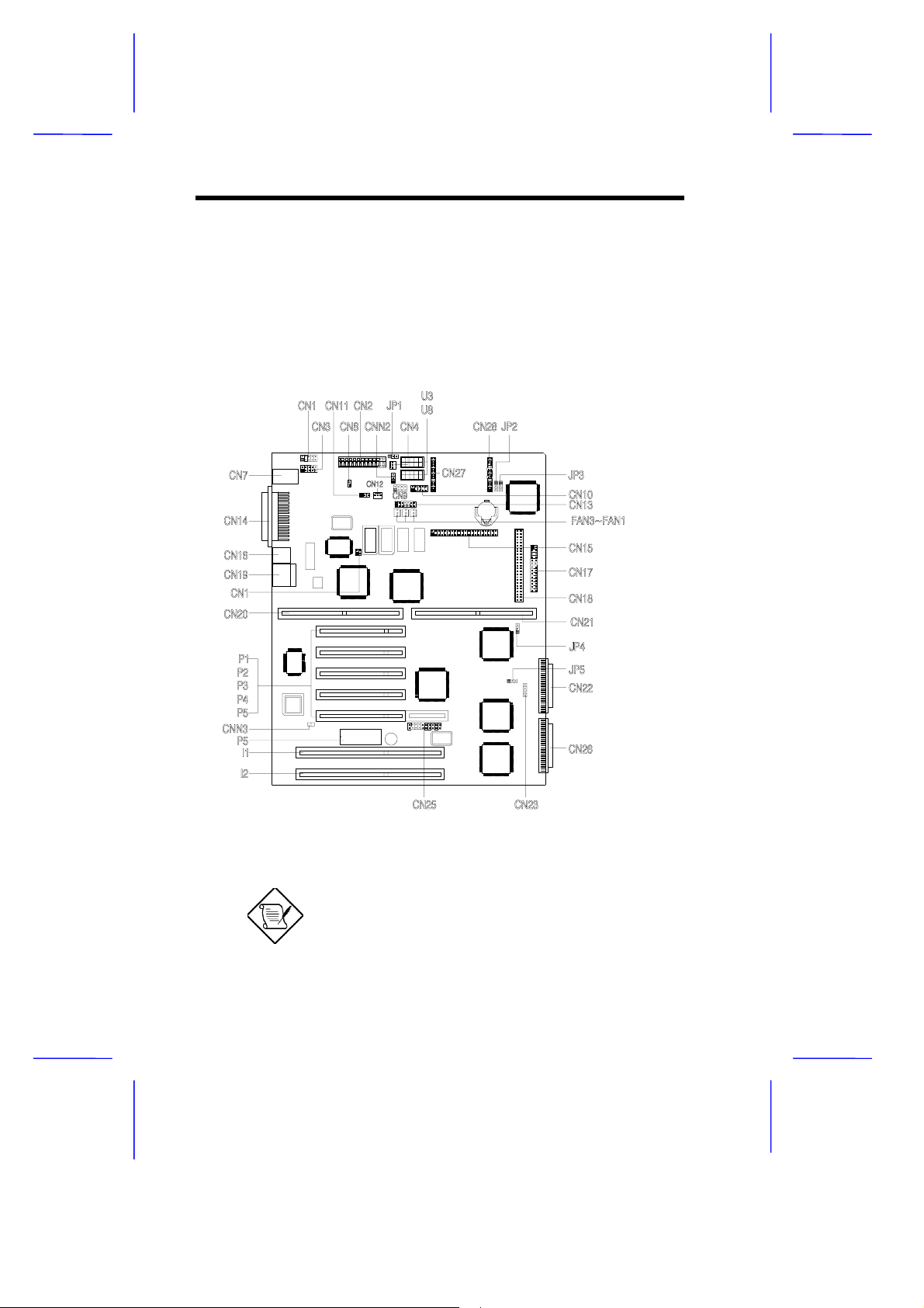
Figure 1-2 shows the jumper and connector locations on the s ystem
board.
Figure 1-2 System Board Jumper and Connector Locations
Jumpers are prefixed “JP”. Connectors are
prefixed “CN”. The blackened pin of a jumper
represents pin 1.
1-4 User’s Guide
Page 5
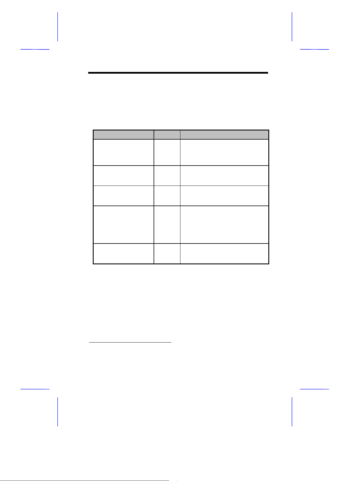
1.4.2 Jumper Settings
Table 1-1 lists the system board jumpers with their corresponding
settings and functions.
Table 1-1 System Board Jumper Settings
Jumper Setting Function
Software Shutdown
Control for CN4
JP1 1-2
BIOS Type
JP2 1-2
Password Security
JP3 1-2
SCSI Channel 1
High-Byte Termination
JP4 1-2*
VGA Feature
JP5 1-2*
*
2-3
2-3*
2-3*
2-3
Open
2-3
Enabled
Disabled
Branded
Generic
Check password
Bypass password
Terminator always set to ON
SCSI terminator set to ON or OFF
by software
Terminator set to OFF
Normal (Auto)
Onboard VGA always disabled
*
Default setting
System Board 1-5
Page 6

1.4.3 Connector Functions
Table 1-2 lists the differ ent connectors on the system board and their
respective functions.
Table 1-2 Connector Functions
Connector Function
CN1 COM 1
CN2, U3, U8 Power connectors
CN3 COM 2
CN4 Software shutdown connector for 420-watt SPS
CN7 PS/2 mouse (above) / keyboard (below) connectors
CN8 Power switch
CN9 Power LED and keylock connector
CN10 Monitor signal connector for redundant power supply
CN12 Software shutdown connector for redundant power
CN13 Backplane board LED connector
CN14 Printer port (above) / video port (below)
CN15 IDE connector
CN16 LAN connector
CN17 Diskette drive connector
CN18 Channel 1 narrow SCSI connector
CN19 Universal serial bus (USB) ports
CN22 Channel 1 wide SCSI connector
CN23 Hard disk LED connector
CN25 SMM connector
CN26 Channel 2 wide SCSI connector
CN27, CN28 RDM connectors
CNN3 Connec tor for chassis intrusion prevention
FA1, FA2, FA3 Fan connectors
supply
1-6 User’s Guide
Page 7

1.5 ESD Precautions
Always observe the following electrostatic discharge (ESD)
precautions before installing a system component:
1. Do not remove a component from its antistatic packaging until
you are ready to install it.
2. Wear a wrist grounding strap before handling electronic
components. Wrist grounding straps are available at most
electronic component stores.
Do not attempt the procedures described in
the following sections unless you are a
qualified technician.
System Board 1-7
Page 8

1.6 Video Memory Upgrade
Larger video memory allows you to display higher resolutions and
more colors. The system board comes with a 1-MB video memory
onboard upgradable to 2 MB.
Follow these steps to upgrade the video memory:
1. Locate the video DRAM upgrade sockets labeled U36 and U37
on the system board. See Figure 1-1.
2. Gently insert a video chip into each of the upgrade sockets.
Make sure that the pin 1 indicator on the chip
matches the notched corner of the socket.
Pin 1 Indicator
Notched Corner
Figure 1-3 Installing a Video Memory Chip
1-8 User’s Guide
Page 9

1.7 ASM Pro
The ASM Pro is a server management tool based on the Simple
Network Management Protocol (SNMP). It detects server problems
related to the CPU thermal condition, 5V/3.3V/1.5V detection, or PCI
bus utilization calculation.
This feature is designed primarily for server supervisors and
management inform ation system (MIS) personnel to help them detect
errors or potential trouble spots in their network servers through a
single management station.
The ASM Pro consists of two major parts:
ASM-Station - a Windows-based monitoring station that
•
communicates with the ASM-Agents.
ASM-Agent(s) - the individual servers managed by the
•
ASM-Station.
Refer to the ASM Pro user’s manual for more information.
System Board 1-9
Page 10

1.8 Remote Diagnostic Management
The Remote Diagnostic Management (RDM) is a network
management tool that utilizes modems and telephone lines to control a
host of servers from a remote station. It monitors and analyzes the
server condition, updates the BIOS settings if necessary, or reboots
the server in the event of failure and quickly return it to normal
operation. This capability to execute the RDM program fr om a rem ote
site bridges the distance barrier in fixing server problem s and reduces
wasted time due to system failure.
1.8.1 Installing the RDM Module
The system board comes with connectors CN27 and CN28 to
accommodate the RDM module.
Follow these steps to install the RDM module and connect the cable:
1. See Figure 1-1 for the location of the RDM connectors.
2. Gently insert the RDM module into CN27 and CN28. The module
fits only in one direction. Do not force it into to the connectors.
CN28
CN27
Figure 1-4 Installing the RDM Module
Refer to the RDM User’s Guide for detailed instructions on RDM
installation.
1-10 User’s Guide
Page 11

1.9 Error Messages
Do not continue using the computer if you receive an error m es sage of
any type. Note the message and take corrective action. This sec tion
explains the different types of error messages and corresponding
corrective measures.
There are two general types of error messages:
Software
•
System
•
1.9.1 Software Error Messages
Software error messages are returned by your operating system or
application. These messages typically occur after you boot the
operating system or when you run your applications. If you receive
this type of message, consult your application or operating system
manual for help.
1.9.2 System Error Messages
A system error message indicates a pr oblem with the computer itself .
A message of this type normally appears during the power-on self-test,
before the operating system prompt appears.
Table 1-3 lists the system error messages.
System Board 1-11
Page 12

Table 1-3 System Error Messages
Message Action
CMOS Battery Error Replace the RTC chip or
contact your dealer.
CMOS Checksum Error Check the RTC chip and the
necessary jumper. If the
battery is still good, run
Setup.
Display Card Mismatch Run Setup.
Diskette Drive Controller
Error or Not Installed
Diskette Drive Error Diskette may be defective. If
Diskette Drive A Type
Mismatch
Diskette Drive B Type
Mismatch
Equipment Configuration
Error
Hard disk Controller Error Run Setup.
Hard disk 0 Error Check all cable connections.
Hard disk 1 Error Check all cable connections.
Keyboard Error or No
Keyboard Connected
Keyboard Interface Error Replace the keyboard or
Check and connect the
control cable to the diskette
controller.
not, replace the diskette drive.
Run Setup and select the
proper drive type.
Run Setup and select the
proper drive type.
Modify the memory
configuration to agree with
one of the options in Table
2-x.
Replace hard disk.
Replace hard disk.
Check and connect the
keyboard to the system unit.
contact your dealer.
1-12 User’s Guide
Page 13

Table 1-3 System Error Messages (continued)
Message Action
Memory Error at:
MMMM:SSSS:OOO
(W:XXXX, R:YYYY)
where:
M: MB, S: Segment,
O: Offset, X/Y: write/read
pattern
Memory Size Mismatch
CPU Clock Mismatch
Onboard Serial Port 1
Conflict
Onboard Serial Port 2
Conflict
Onboard Parallel Port Conflict Run Setup and disable the
Pointing Device Error Check and connect pointing
Pointing Device Interface
Error
Press F1 key to continue or
Ctrl-Alt-Esc for Setup
Real Time Clock Error Check the RTC chip. If it is still
CPU BIOS Code Mismatch Contact your dealer.
Check installed DIMMs.
Contact your dealer.
Run Setup. Check if the values
shown in the memory
parameters are correct. If
correct, exit Setup and reboot
the system. If the error
message reappears, seek
technical assistance.
Run Setup and disable the
port.
Run Setup and disable the
port.
port.
device.
Replace the pointing device or
contact your dealer.
Press
Setup.
good, run Setup. If not, replace
the RTC chip.
or
+ + to enter
System Board 1-13
Page 14

1.9.3 Correcting Error Conditions
As a general rule, if an error message says "Press F1 to continue," it is
caused by a configuration problem, which can be easily corrected. An
equipment malfunction is more likely to cause a fatal error, i.e., an
error that causes complete system failure.
Here are some corrective measures for error conditions:
1. Run Setup. You must know the correct configuration values for
your system before you enter Setup, which is why you should
write them down when the system is correctly configured. An
incorrect configuration is a major cause of power-on error
messages, especially for a new system.
2. Remove the system unit cover. Check that the jumpers on the
system board and any expansion boards are set correctly.
3. If you cannot access a new disk, it m ay be because your disk is
not properly formatted. Format the disk fir st using the FDISK and
FORMAT commands.
4. Check that all connectors and boards are securely plugged in.
If you go through the corrective steps above and still receive an error
message, the cause may be an equipment malfunction.
If you are sure that your configuration values are correct and your
battery is in good condition, the problem may lie in a damaged or
defective chip.
In either case, contact an authorized service center for assistance.
1-14 User’s Guide
 Loading...