

Page 1
System Board
1.1 Features
The M9A is a dual-processor system board that supports the Intel
P54C and P55C CPUs. The board contains an exc lusiv e slot for the
CPU board that carries the 321-pin zero-insertion force (ZIF) CPU
sockets plus the embedded 512-KB pipeline burst second-level
cache.
This high-perf orm ance 64-bi t system board utilizes both the EISA and
the PCI loc al bus architecture. Two EISA, four PCI bus slots, and one
EISA/PCI shared slot reside on the board to allow installati on of either
master or slave devices.
The system board has four DRAM banks composed of eight 72-pin
SIMM sockets that accommodate both fast-page mode and EDO
(extended dat a output) SIMMs. The sockets support a tot al of 512MB system memory using 64-MB SIMMs.
A 50-pin Fast SCSI-II interface and a 68-pin Wide SCSI interface
come with the system board to connect SCSI devices. Standard
external I/O interfaces include two 9-pin serial ports, one par all el port ,
a video port, and keyboar d and mouse ports.
The system board supports two optional features that allow better
server management, the ASM Pro and the remote diagnostic
management (RDM). The ASM Pro detects system problems, such
as CPU thermal condi tion, 5V/ 3.3V detecti on, and PCI bus utilization
calculat ion. The RDM all ows execution of a diagnosti c program f rom
a remote stat ion to f ix the detected problems or to reboot t he system.
System Board 1-1
Page 2

1.2 Major Components
The system board has the following major components:
•
Four DRAM banks com posed of eight 72-pi n SIMM sockets that
support single- and doubl e- densi ty 60 ns SIMMs
•
CPU board slot
•
Four PCI, two EISA bus slots, and one EISA /PCI shared slot
•
256-KB Flash ROM for system BIOS
•
System clock/calendar plus 8 KB extended CMOS RAM with
battery backup
•
50-pin Fast SCSI-II and 68-pin W ide SCSI i nterfaces
•
Two 24-pin RDM int er faces
•
IDE hard disk and di sket te drive inter faces
•
Onboard VRAM and VRAM sockets for video memory upgrade
•
Power connector f or 350- watt or 420- watt switc hing power supply
•
Super I/O, SCSI, VGA, memory, and Advanced Server
Management (ASM) control ler chipsets
•
External ports:
• Two 9-pin serial por ts
• PS/2-compatibl e k ey boar d por t (optional AT-keyboard por t)
• PS/2-compatibl e mouse port
• Parallel port
• Video port
1-2 User’s Guide
Page 3
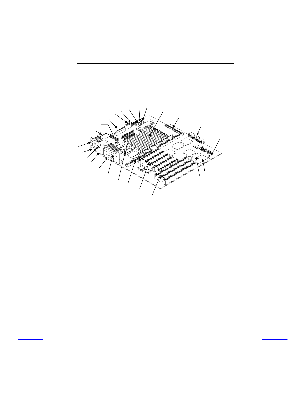
1.3 Layout
6
7
Figure 1-1 shows the system board components.
19
20
21
22
23
24
1
2
3
4
5
1 COM1
2 COM2
3 Mouse port
4 Keyboard port
5 Video port
6 Parallel port
7 Video upgrade sockets
8 CPU board slot
9 PCI slots
10 EISA slots
11 Real-time clock
12 Flash ROM BIOS
18
8
17
16
15
14
13
12
11
9
10
13 Buzzer
14 Narrow SCSI connector
15 W ide SCSI connector
16 SIMM sockets
17 Fan connector 1 ( FA1)
18 Fan connector 2 ( FA2)
19 Fan connector 3 ( FA3)
20 420W 5V standby power connector
21 Power connect or
22 Power connect or
23 Video RAM
24 RDM connectors
Figure 1-1 System Board Layout
System Board 1-3
Page 4
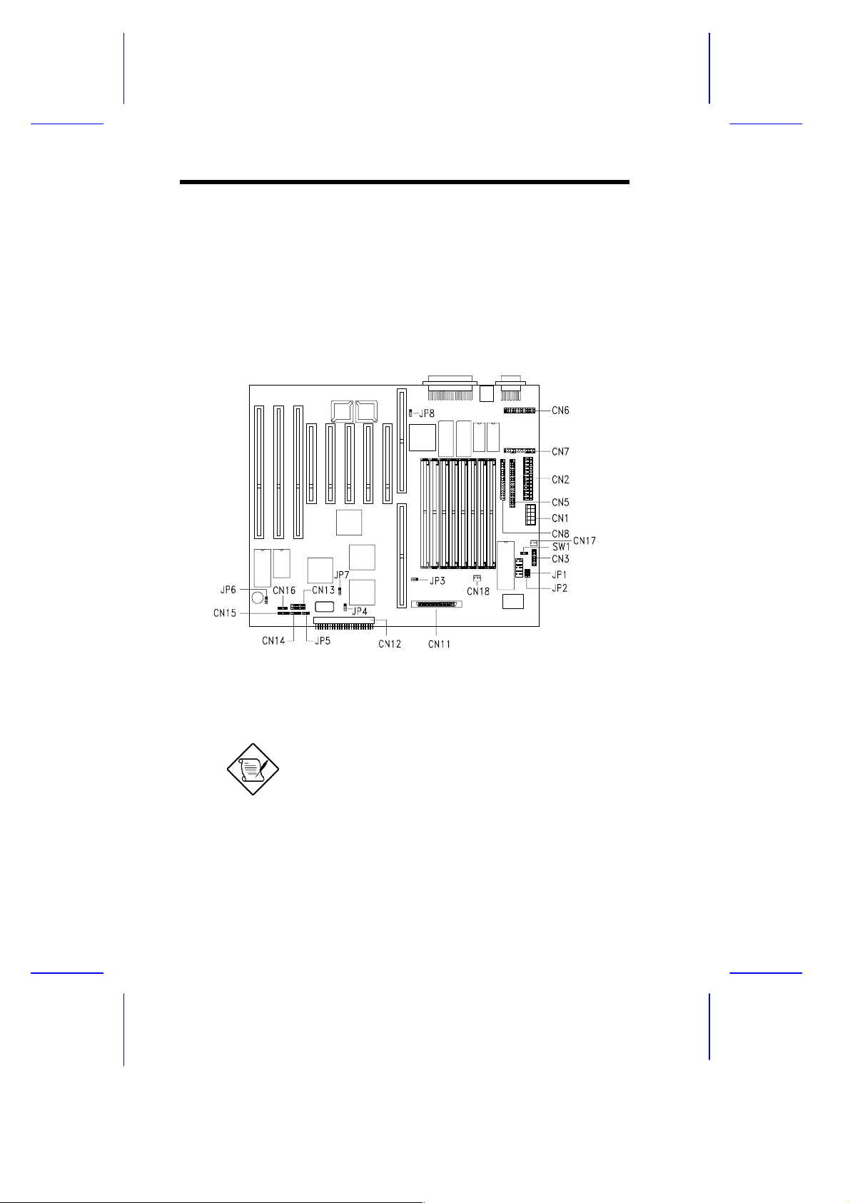
1.4 Jumpers and Connectors
1.4.1 Jumper and Connector Locations
Figure 1-2 shows the jum per and connector l ocations on t he system
board.
Figure 1-2 System Board Jumper and Connector Locations
Jumpers are prefixed “JP”. Connectors are
prefixed “CN” and “SW.
The blackened pin of a jumper r epr es ents
pin 1.
1-4 User’s Guide
Page 5
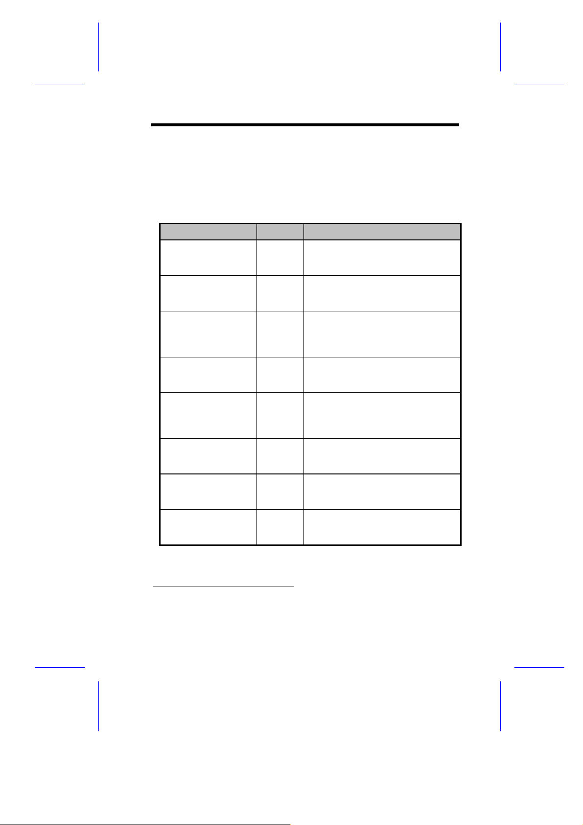
1.4.2 Jumper Settings
Table 1-1 lists the system board jumpers with their corresponding
settings and func tions.
Table 1-1 System Board Jumper Settings
Jumper Setting Function
Password Security
JP1 1-2
BIOS Type
JP2 1-2*
SCSI Termi n ation
JP3 1-2
SCSI Selection
JP4 1-2*
Hardware Reset
JP5 1-2
Sound Feature
JP6 1-2*
SCSI Feature
JP7 1-2*
VGA Feature
JP8 1-2*
2-3
2-3
2-3*
2-3
2-3*
3-4
2-3
2-3
2-3
*
Check password
Bypass password
Acer
OEM
Terminator al ways set to ON
Use SCSI Setup Utility to set
terminator to ON or OFF
Wide SCSI
Standard
Software shutdown enabled
Hardware reset enabled
Hardware reset button connector
Buzzer
Speaker
Enabled
Disabled
Enabled
Disabled
*
Default setting
System Board 1-5
Page 6
1.4.3 Connector Functions
Table 1-2 l ists the dif f erent c onnectors on the system board and their
respective func tions.
Table 1-2 Connector Func tions
Connector Function
CN1 Power connector
CN2 Power connector
CN3 Backplane board HDD stat us c onnector
CN5 IDE hard disk connector
CN6 RDM connector
CN7 RDM connector
CN8 Diskette drive connector
CN11 68-pin Wide SCSI connector
CN12 50-pin Fast SCSI-II connector
CN13 RDM cable and LED board connector
CN14 Hard disk LED connector
CN15 Power LED connector
CN16 Speaker connector
CN17 420W 5V standby power connector
CN18 200W 5V standby power connector
SW1 NMI switch
1-6 User’s Guide
Page 7

1.5 ESD Precautions
Always observe the following electrostatic discharge (ESD)
precautions before installing a system c omponent:
1. Do not remov e a component from its antistatic packaging until
you are ready to i nstall it.
2. Wear a wrist grounding strap before handling electronic
components. Wrist grounding straps are available at most
electronic component stor es.
Do not attempt t he procedures described in
the following sec tions unless you are a
qualified technician.
1.6 Memory Upgrade
The system board comes with eight 72-pi n SI MM socket s that support
4-MB and 16-MB single-density SIMMs as well as 8-MB and 32-MB
double-density SIMMs for a total system memory of 256-MB. The
sockets support both the fast page mode and EDO 60 ns SI M M s.
See Table 1-3 for a list of some possible mem or y c onfigurations.
1.6.1 Rules for Adding Memory
•
Use only one type of SIMM in a giv en bank. You m ay combi ne
diff erent types of SI MMs for a mem ory confi guration as long as
the SIMMs in eac h bank ar e of the same type.
•
You may use the memory banks (Bank 0 ~ Bank3) in any or der .
•
Always install SIMMs in pairs. For example, for a total memory
of 16 MB, install two 8-MB SIMMs in a bank. You can not use a
16-MB SIMM alone for a 16-MB memory.
System Board 1-7
Page 8

1.6.2 Memory Configurations
Table 1-3 Memory Configur ations
Bank0 Bank1 Bank2 Bank3 Total
S1 S2 S3 S4 S5 S6 S7 S8 Memory
8 MB 8 MB 16 MB
16 MB 16 MB 32 MB
32 MB 32 MB 64 MB
64 MB 64 MB 128 MB
8 MB 8 MB 16 MB 16 MB 48 MB
8 MB 8 MB 32 MB 32 MB 80 MB
16 MB 16 MB 32 MB 32 MB 96 MB
64 MB 64 MB 32 MB 32 MB 192 MB
8 MB 8 MB 16 MB 16 MB 48 MB
8 MB 8 MB 16 MB 16 MB 16 MB 16 MB 80 MB
8 MB 8 MB 16 MB 16 MB 32 MB 32 MB 112 MB
8 MB 8 MB 16 MB 16 MB 32 MB 32 MB 64 MB 64 MB 240 MB
8 MB 8 MB 8 MB 8 MB 16 MB 16 MB 16 MB 16 MB 96 MB
8 MB 8 MB 8 MB 8 MB 32 MB 32 MB 32 MB 32 MB 160 MB
16 MB 16 MB 16 MB 16 MB 32 MB 32 MB 32 MB 32 MB 192 MB
32 MB 32 MB 32 MB 32 MB 64 MB 64 MB 64 MB 64 MB 384 MB
8 MB 8 MB 8 MB 8 MB 8 MB 8 MB 8 MB 8 MB 64 MB
16 MB 16 MB 16 MB 16 MB 16 MB 16 MB 16 MB 16 MB 128 MB
32 MB 32 MB 32 MB 32 MB 32 MB 32 MB 32 MB 32 MB 256 MB
64 MB 64 MB 64 MB 64 MB 64 MB 64 MB 64 MB 64 MB 512 MB
The above configurat ions ar e only s om e of
the available memory com binations. You
can use other combinat ions as long as y ou
follow the rules for upgrading memory in
section 1.6.1.
1-8 User’s Guide
Page 9

1.6.3 Installing a SIMM
Follow these steps to install a SIM M :
1. Careful ly slip a SIMM at a 45° angle into a socket m aking sure
that the curv ed edge indicati ng the pin 1 of the SIMM matches
pin 1 of the socket.
A SIMM fits only in one dir ec tion. If you slip
in a SIMM but would not c om pletely fit, y ou
may have inserted it the wrong w ay .
Reverse the orientation of the SIMM.
2. Gently push the S IMM to a v er tic al posi tion until t he pegs of t he
socket slip into t he hol es on the SIM M, and t he hol ding c li ps loc k
the SIMM into position. The SIMM should be at a 90° angle
when installed.
1
Pin 1 Indicator
(curved edge)
Figure 1-3 Installing a SIMM
System Board 1-9
2
Peg
Hole
Page 10

1.6.4 Removing a SIMM
Follow these steps to remove a S IMM:
1. Press the holding clips on both sides of the SIMM outward to
release it.
2. Move the SIMM to a 45° angle.
3. Pull t he S IMM out of the socket.
Holding Clip
1
3
2
Figure 1-4 Removing a SIMM
1-10 User’s Guide
Page 11

1.6.5 Reconfiguring the System
You must enter Setup after installing or removing SIMMs to
reconfigure the system.
Follow these steps to reconfigure t he system:
1. Turn the system on. A memory error message appears,
indicat ing t hat t he tot al m em ory does not m atc h t he v al ue stored
in CMOS.
2. Press
appears indicating an incorrec t mem or y c onfiguration.
3. Press
The system boots with t he new m emory configuration.
+ + to enter Setup. A warning message
twice to ex it and reboot t he system.
If you run Windows NT, NetWar e, or
UnixWare in the system, make sure to run
ECU every time you c hange the memory
size. See Chapter 4 for inform ation on ECU.
System Board 1-11
Page 12

1.7 Video Memory Upgrade
Larger video memory allows you to display higher resolutions and
more colors. The system board comes with a 1-MB video memory
onboard upgradable to 2 MB .
Follow these steps to upgrade the vi deo memory :
1. Locate the v ideo DRAM upgrade sockets labeled U18 and U21
on the system board. S ee Figure 1-1.
2. Gently insert a video chip into each of the upgrade sockets.
Make sure that the pin 1 indicator on the c hip
matches the not c hed c or ner of the socket .
Pin 1 Indicator
Notched
Corner
Figure 1-5 Installing a Video Memor y Chip
1-12 User’s Guide
Page 13

1.8 PCI Slot Configuration
1.8.1 PCI-to-PCI Bridge Feature
The system board carr ies a PCI-to-PCI bri dge controll er chipset that
expands the capability of the PCI system by allowing all the five PCI
slots in the system to be bus m asters. The br idge has t wo i nterfaces.
The primary interface connects directly to the PCI bus close to the
host CPU. The secondary interfac e creates a new PCI bus that can
operate independently fr om the pri mary PCI bus.
1.8.2 Installing PCI Devices
The devi ces you install in PCI sl ots 1 and 2 operate on the primary
PCI bus while those in PCI slot s 3, 4, and 5 oper ate on t he secondary
PCI bus.
Since the primary PCI bus operates faster than the secondary PCI
bus, install PCI add-on boards in PCI slots 1 and 2 f irst then on PCI
slots 3, 4, and 5 to achiev e better system performanc e. See Figure
1-1 for t he locations of the PCI slots.
System Board 1-13
Page 14

1.9 ASM Pro
The ASM Pro is a server management tool based on the Simple
Network Management Protocol (SNMP). It detects server problems
related to t he CPU thermal c ondition, 5V/3.3V detec tion, or PCI bus
utilization calculation.
This feature is designed primarily for server supervisors and
management i nf orm at ion system (MIS ) personnel t o hel p t hem detect
errors or potential trouble spots in their network servers through a
single management station.
The ASM Pro consists of two major parts:
•
ASM-Station - a Windows-based monitoring station that
communicates with the ASM-Agents.
•
ASM-Agent(s) - the individual servers managed by the
ASM-Station.
Refer to the ASM Pro user’s manual for more i nformation.
1-14 User’s Guide
Page 15

1.10 Remote Diagnostic Management
The Remote Diagnostic Management (RDM) is a network
management tool t hat utilizes modems and telephone li nes to cont rol
a host of serv ers f rom a r em ote stat ion. It m oni t ors and anal yzes t he
server condi tion, updates the BIO S settings if necessary, or reboots
the server in the event of failure and quickly return it to normal
operation. This capability to execute the RDM program from a
remote sit e bridges the di stance barri er in f ix ing serv er pr oblem s and
reduces wasted time due to system failure.
1.10.1 Installing the RDM Module
The system board comes with connectors CN6 and CN7 to
accommodate the RDM module, and CN13 to connect the RDM
cable.
Follow these steps to install the RDM module and connect the cable:
1. See Figure 1-1 for the location of the RDM connectors.
2. Gently i nsert the RDM m odule into CN6 and CN7. The m odule
fits only in one di r ec tion. Do not force i t into to the connectors.
CN6
CN7
Figure 1-6 Installing the RDM M odule
System Board 1-15
Page 16

3. Insert the cable end with the RDM button into the slot on the
housing front panel.
4. Attach the ot her end of t he RDM cabl e t o CN13 (pi ns 5-6, 11-12)
on the system board. Note that the covered pin of the cable
connector does not connect to any pin.
RDM Cable
CN13
12
1
7
Figure 1-7 Connecting the RDM Cable
Refer to the RDM User’s Guide f or detailed instr uctions on the RDM
installation.
1-16 User’s Guide
Page 17

1.11 Error Messages
Do not continue usi ng the computer if you receiv e an error m essage
of any type. Note the message and take corrective action. This
section explains the different types of error messages and
corresponding corrective measures.
There are two general t y pes of error m essages:
•
Software
•
System
1.11.1 Software Error Messages
Software error messages are returned by your operating system or
application. These messages typically occur after you boot the
operating system or when you run your appli cations. If you receive
this type of message, consult your application or operating system
manual for help.
1.11.2 System Error Messages
A system error message indicates a problem with the c omputer itself .
A message of this type normally appears during the power-on selftest, bef or e the operating system prompt appear s.
Table 1-4 l ists the system error messages.
System Board 1-17
Page 18

Table 1-4 System Error Messages
Message Action
CMOS Battery Error Replace the RTC chip or
contact your dealer.
CMOS Checksum Error Check the RTC chip and the
necessary jumper. If the
battery is still good, run
Setup.
Display Card Mismat ch Run Setup.
Diskette Dr ive Controller
Error or Not Installed
Diskette Drive Error Diskette may be defective. If
Diskette Drive A Type
Mismatch
Diskette Drive B Type
Mismatch
Equipment Configuration
Error
Hard disk Controller Error Run Setup.
Hard disk 0 Error Check all cable connections.
Hard disk 1 Error Check all cable connections.
Keyboard Error or No
Keyboard Connected
Keyboard Interface Error Replace the keyboar d or
Check and connect the
control cable to the diskette
controller.
not, replace the diskette drive.
Run Setup and select the
proper drive type.
Run Setup and select the
proper drive type.
Modify the m emory
configurati on t o agr ee with
one of the options in Table
1-3.
Replace hard disk.
Replace hard disk.
Check and connect the
keyboard to the system unit.
contact your dealer.
1-18 User’s Guide
Page 19

Table 1-4 System Error Messages (continued)
Message Action
Memory Error at:
MMMM:SSSS:OOO
(W :XXXX, R:YYYY)
where:
M: MB, S: Segment,
O: Offset, X/Y: write/read
pattern
Memor y Size Mismatch
CPU Clock Mismatch
Onboard Serial Port 1
Conflict
Onboard Serial Port 2
Conflict
Onboard Parallel Port
Conflict
Pointing Device Error Check and connect pointing
Pointing Device Interface
Error
Press F1 key to continue or
Ctrl-Alt-Esc for Setup
Real Time Clock Error Check the RTC chip. If it is
Check SIMMs on the system
board. Contact your dealer.
Run Setup. Check if the
values shown in the memory
parameters are correct. If
correct, exit Setup and reboot
the system. If the error
message reappears, seek
technical assistance.
Run Setup and disable the
port.
Run Setup and disable the
port.
Run Setup and disable the
port.
device.
Replace the pointing device or
contact your dealer.
Press
Setup.
still good, run Setup. If not,
replace the RTC chip.
or
+ + to enter
System Board 1-19
Page 20

1.11.3 Correcting Error Conditions
As a general rule, if an error m essage says "Press F1 t o conti nue," it
is caused by a confi guration probl em, which can be easily corrected.
An equipment malfunction is more likely to cause a fatal error, i.e., an
error that causes com plete system fail ur e.
Here are some corrective measures for er r or c onditions:
1. Run Setup. You m ust know the correct configur ation v alues for
your system before you enter Setup, which is why you should
write them down when the system is correctly configured. An
incorrect configuration is a major cause of power-on error
messages, especially for a new system.
2. Remov e the system unit c over. Check t hat the jum pers on the
system board and any ex pansi on boar ds are set cor r ec tly.
3. If you cannot access a new disk, it m ay be because your disk is
not properly formatted. Format the disk first using the FDISK
and FORMAT c ommands.
4. Check that al l connectors and boards are securely plugged in.
If you go t hrough t he correc ti ve steps above and still receive an error
message, the cause may be an equipment malfunction.
If you are sure that your configuration values are correct and your
battery is in good condition, the problem may lie in a damaged or
defectiv e c hip.
In either c ase, c ontact an authorized service center for assistance.
1-20 User’s Guide
 Loading...