

Page 1
System Board
The system board is designed with 32-/64-bi t auto-det ect, aut o-switch
architecture. It is a high-peformance board that support s both the 486
series and the new Pentium microprocessors, making the
486/Pentium system a performance machine that will last well into the
future.
It featur es single-chip upgrade technology t hat makes CPU upgrades
easy and economical . It i s full y compati ble with the IBM P C/AT and
is suitable f or use as a multiuser f ile serv er, LAN file server or as a
CAD/CAE/CAM workstation.
The system board supports 128-KB system ROM, five 16-bit ISA
expansion slots, three PCI local bus slots, a CPU board slot, four
72-pin DRAM sockets, two IDE connec tors and one SCSI connector
(for SCS I models). Standard f eatures such as two serial ports, one
parallel port, a diskette driv e interface and an embedded fix ed disk
drive interface also reside on the system board.
The system board supports a m axim um mem ory of 128 MB using 4and 16-MB single-density, 8- and 32-MB (with parity) double-density,
and 2-MB (without parity) SIMMs.
System Board 1-1
Page 2

1.1 Major Components
The system board has the following major components:
•
Four 72-pin SIMM sockets arranged in t wo banks (labeled
Bank 0 and Bank 1)
•
DRAM controller with page/faster page mode and burst read
capability
•
One CPU board slot
•
Four 16-bit ISA expansion slots supporting master add-on c ar ds
•
Two PCI slots
•
One full-f unc tion ISA/ P CI slot
•
Real-ti me clock with 5-7-year batter y
•
128-KB flash ROM used as system BIOS
•
PS/2 keyboard and mouse interface
•
Reset and front- panel LED interface f or ID3P or IDAB housing
•
Onboard National P C87332 chip that supports one parall el port,
two serial ports, one I DE por t, and one FDD port
•
Onboard AIC-7850 chip t hat supports one 8-bit SCSI- II port (one
port supports seven devices)
•
Enhanced IDE (PCI to IDE) on PCI bus that supports two IDE
ports for four IDE devices
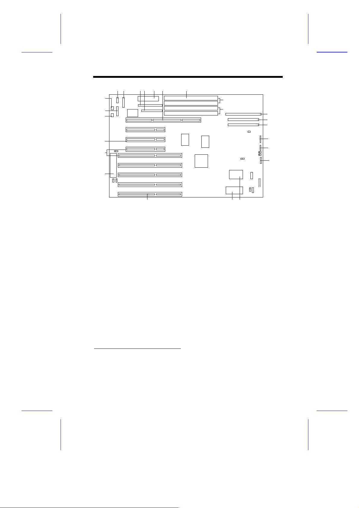
Figure 1-1 shows the system board layout and the locations of the
major c omponents.
1-2 User’s Guide
Page 3
1 2 3 4 5 6 7
1 2345 6
22
21
22
21
20
19
19
18
18
17
17
16
BANK 1
BANK 020
8
7
8
9
9
10
10
11
11
12
12
13
16 15 14
1COM2
2 Printer port
3 IDE connector
4 FDD connector
5 Power connector
6 CPU board slot
7 SIMM sockets
8 SCSI connector
9 Enhanced IDE1 connector
10 Enhanced IDE2 connector
11 Power LED connector
1
12 HDD LED connector
13 Reset/SMI connector
14 Real-time clock
15 System BIOS (flash ROM)
16 ISA slots
17 Keyboard controller
18 ISA/PCI slot
19 PCI slots
20 PS/2 mouse connector
21 COM1
22 PS/2 keyboard connector
131415
2
Figure 1-1 System Board Layout
1
The connector version varies depending on the system housing. The system may
come w i th either an IDAB or an ID3P housing.
2
You cannot use both slots at the same time.
1
1
System Board 1-3
Page 4

1.2 ESD Precautions
Electrostatic discharge (ESD) can damage your processor, disk
drives, expansion boards, and other components. Always observe
the following precautions before you install a system component.
1. Do not rem ove a component from i ts protecti ve pack aging until
you are ready to i nstall it .
2. W ear a wrist grounding strap and attach it to a met al part of the
system unit bef ore handling com ponents. If a wrist strap is not
avai lable, mai ntain contact with the system unit throughout any
procedure requiring ESD protect ion.
1.3 Pre-installation Instructions
Always observe the foll owing before you install a system component:
1. Turn of f the system power and all t he peripherals connected to
the unit before opening i t.
2. Open the system according to the instructions in the housing
install ation manual.
3. Follow the ESD precautions in section 1.2 before handling a
system component.
4. Remov e any expansion boards or peri pherals that bl ock access
to the SIMM sockets or CPU socket.
5. See the following sections for specific instructions on the
component you wish to install.
Do not attempt t he procedures described in
the following sections unless you are a
qualified service tec hnic ian.
1-4 User’s Guide
Page 5

1.4 Upgrading the CPU
The system has a separate board f or the CPU and the second-lev el
cache. The single-chip upgrade t echnol ogy gi v es you t he f l ex ibility to
upgrade the CPU by sim ply i nserting a hi gher 486 CPU or a Pent ium
CPU. Refer to Chapter 2 f or detail ed i nstructi ons on how t o upgrade
the CPU.
1.5 Jumper Settings
You have to change the jumper settings on the system board
whenever you reconfigure t he system.
Follow these steps to change a j umper setting:
1. Shut off the system power.
2. Remove the jumper cap f r om the jumper.
3. Position the jumper cap over the two pins for the desired
function.
4. Gentl y pr ess the cap into place.
Figure 1-2 shows the jum per locations.
System Board 1-5
Page 6
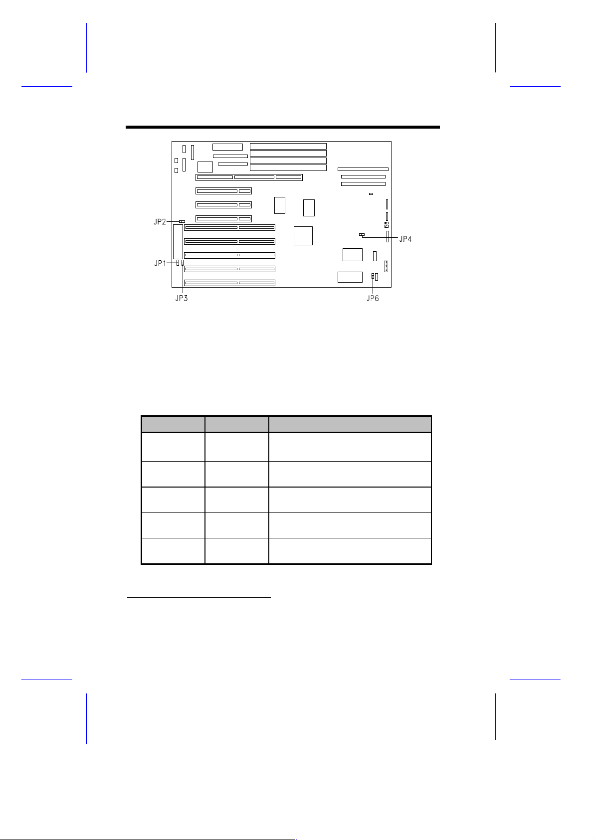
Figure 1-2 System Board Jumper Locations
Table 1-1 lists the system board jumpers settings and their
corresponding f unc tions.
Table 1-1 System Board Jumper Settings
Jumper Setting Function
JP1
JP2 1-2*
JP3 1-2*
JP4 1-2*
JP6 1-2*
*
2-3
1-2
Open
2-3
2-3
2-3
Disregards password
Enables password
Enables reset function
Disables reset function
BIOS
Reserved
128 bytes or 256 bytes (NVRAM)
4 Kbytes, reserved (NVRAM)
Enables onboard buzzer
Enables external speaker
*
Default setting
1-6 User’s Guide
Page 7

Use JP4 to select the desired RTC. For
models with onboard SCSI, the available
options are BQ3287E or B Q3287EA.
1.6 Upgrading the Memory
You can upgrade the system memory by adding single in-line
memory modules (SIMMs) or by changing the SIMMs for a higher
memory configuration. The system supports 4- and 16- MB singledensity, 8- and 32-MB (with pari ty) double-densit y, and 2-MB (without
parity) SIMMs. The four 72-pin SIMM sockets are arranged in two
banks, with two SIMMs per bank.
Table 1-2 Memory Configur ations
Bank 0 Bank 1 Total
512 KB x 32 x 2 4 MB (w/out parity)
1 MB x 36 x 2 8 MB
1 MB x 36 x 2 512 KB x 32 x 2 12 MB
1 MB x 36 x 2 1 MB x 36 x 2 16 MB
512 KB x 32 x 2 2 MB x 36 x 2 20 MB
1 MB x 36 x 2 2 MB x 36 x 2 24 MB
1 MB x 36 x 2 4 MB x 36 x 2 40 MB
1 MB x 36 x 2 8 MB x 36 x 2 72 MB
2 MB x 36 x 2 16 MB
2 MB x 36 x 2 1 MB x 36 x 2 24 MB
2 MB x 36 x 2 2 MB x 36 x 2 32 MB
512 KB x 36 x 2 4 MB x 36 x 2 36 MB
2 MB x 36 x 2 4 MB x 36 x 2 48 MB
2 MB x 36 x 2 8 MB x 36 x 2 80 MB
System Board 1-7
Page 8

Table 1-2 Memory Configur ations (continued)
Bank 0 Bank 1 Total
4 MB x 36 x 2 32 MB
4 MB x 36 x 2 1 MB x 36 x 2 40 MB
4 MB x 36 x 2 2 MB x 36 x 2 48 MB
4 MB x 36 x 2 4 MB x 36 x 2 64 MB
512 MB x 36 x 2 8 MB x 36 x 2 68 MB
4 MB x 36 x 2 8 MB x 36 x 2 96 MB
8 MB x 36 x 2 64 MB
8 MB x 36 x 2 1 MB x 36 x 2 72 MB
8 MB x 36 x 2 2 MB x 36 x 2 80 MB
8 MB x 36 x 2 4 MB x 36 x 2 96 MB
8 MB x 36 x 2 8 MB x 36 x 2 128 MB
1.6.1 Installing SIMMs
Observe the ESD precautions when
installing components. See section 1.2.
Follow these steps to install a SIMM :
1. Sli p a S IMM at a 45
o
angle into a socket with the com ponent side
faci ng down. Always install SI M M s begi nning with bank 0.
Be careful when inserting or removing
SIMMs. Forcing a SIMM into or out of a
socket can damage t he socket or the S IMM
(or both).
1-8 User’s Guide
Page 9

2. Gentl y push the S IMM up until the pegs of the socket sl ip into the
holes on the SIMM and the holding clips lock the SIMM into a
vertical position.
The SIMM should be at a 90o angle when
installed.
Make sure that the two SIMMs on each bank
are identical.
Figure 1-3 Installing a SIMM
1.6.2 Removing SIMMs
1. Press the holding clips on both sides of the SIMM outward to
release it.
2. Press the SIMM downward to about a 45
3. Gentl y pull the SI M M out of the socket .
System Board 1-9
o
angle.
Page 10

Figure 1-4 Removing a SIMM
Always remove SIMMs from the highest
bank first.
1.6.3 Reconfiguring the System
Always reconfigure the system after installing or remov ing SIMMs.
Follow these steps to reconfigure the system:
1. Reboot the system. A memory error message appears,
indicat ing t hat t he tot al m em ory does not m atc h t he v al ue stored
in CMOS.
2. Press
3. Press
The system boots with t he new m emory configurati on.
1-10 User’s Guide
A warning message indic ates an incorrect memory configurat ion.
twice to ex it Setup and reboot the system.
to enter Setup.
Page 11

1.7 SCSI Feature
For Small Computer System Interface (SCSI) models, the system
board features a fast, si ngle- chi p SCSI -2 host adapter that adds SCSI
I/O capability to the system. The device consists of all the
components f ound on the stat e-of - the-ar t SCS I host adapters such as
an onboard mic rocont rol ler , bus m aster i nterface control l er, and SCSI
controllers. Through the PCI bus, this dev ice can transfer at a full
132-MB/second burst transfer rate.
Refer to the SCSI manual for more
information.
1.8 Enhanced IDE Feature
The system board comes with two enhanced IDE connectors. The
enhanced IDE eli minates many of the exi sting li mitati ons associated
with the current IDE int erf ace. The f ol lowing ar e the special f eatures
of the enhanced IDE:
•
Four IDE devices with dual -channel I DE and m ul ti pl e I DE device
connectors
•
Non-disk peripherals (IDE CD-ROM)
•
Higher capacity fixed disk through LBA mode translation
(up to 8.4G)
•
Data transfer rates can be increased through t he Advanced PIO
mode support
System Board 1-11
Page 12

To make use of the enhanced IDE features, you need to instal l the
enhanced IDE driv ers. To install, simply insert t he utility driver into
the diskette dr ive and open the README file. You can f ind all the
necessary information and instructions in the README file. For more
infor mation about the install ation procedures under dif ferent oper ating
systems, read the README.XXX found in the subdirectory of the
target operati ng system . F ol low the i nstall at ion i nstruct i ons shown on
the screen.
1.9 Installing the System Board
The system uses either an ID3P or IDAB housing. Refer to the
housing manual for more information on how to install the system
board.
1.9.1 LED Connectors and Reset Switch
Power LED Connector
The Power LED connector has two pins with two colored wires. Thi s
connector may come either with green and white wires (for IDAB) or
green and black wires (for ID3P). In each case, the green wire
indicat es pi n 1. When c onnec ting, take note of the location of pin 1.
HDD LED Connector
This 4-pin connector with two colored wires is for the HDD LED
functi on. This connector may come ei ther with red and white wires
(for IDAB) or red and black wires (f or ID3P). In each case, the red
wire indicat es pin 1. When connect ing, take note of the locati on of
pin 1.
1-12 User’s Guide
Page 13

Turbo LED Connector
The Turbo LED connector has two pins with yell ow and white wires.
The yell ow wire indicates pin 1. To connect, plug t he connector into
the Reset/SMI c onnector on the m ain boar d. Make sure that pin 1 of
the Turbo LED connector corresponds to pin 1 of the Reset/SMI
connector. See Figure 1-1 for the location of the Reset/SMI
connector. See Figure 1-5 for the proper connect ion.
Reset Switch
The Reset switch is a two-pin connec tor with purple and white wires.
It is a non-directional connector. To connect, simply plug this
connector into the Reset/SMI connector on the mainboard. See
Figure 1-1 for the l ocati on of t he Reset/S MI c onnector . See F i gure 15 for the pr oper c onnec tion.
The descriptions above apply only to IDAB
housing connectors. For ID3P housings , the
Turbo LED connector and the Reset switch
are combined in one 8-pin connector. To
connect, simply plug the 8-pin connector to
the Reset/SMI connector on the
motherboard. Take note of pin 1 as shown
in Figure 1-5.
System Board 1-13
Page 14

1.9.2 Reset/SMI Connector
1
D
Reset Switch
The Reset/SMI connector is locat ed on the mot herboard. I t has eight
pins and supports both the Turbo LED and Reset switch functions.
Take note of the location of pi n 1 on the Reset/SMI connector. Figure
1-5 shows you how and where to connect the Turbo LED and the
Reset switch connectors.
PIN 1
Turbo LE
Figure 1-5 Reset/S M I Connector
1.10 Post-installation Instructions
Observe the following after installing a system component:
1. See to it that al l com ponents are i nstall ed acc ording to t he stepby-step instruct ions in their r espect ive sect ions.
2. Make sure you hav e set the required jum pers. See section 1.5
for the correct jumper settings.
3. Replace any ex pansion boards or peripherals that you remov ed
earlier.
4. Replace the system cov er .
5. Connect the necessary cables and turn on the system.
1-14 User’s Guide
Page 15

1.11 Error Messages
In the event that y ou recei ve an error m essage, do not cont inue usi ng
the computer. Note the message and take corrective action
immediately. This section describes the different types of error
messages and suggests corrective measures.
There are two general t y pes of error messages:
•
Software
•
System
1.11.1 Software Error Messages
Software error messages are returned by your operating system or
application. These messages typically appear after you boot the
system or when you run your appli cati ons. If you recei v e this ty pe of
message, consult your application or operating system manual for
help.
1.11.2 System Error Messages
A system error message indicates a problem with the c omputer itself .
These messages normally appear during the power-on self-test,
before the operating system prompt appears. Table 1-3 lists the
system error messages in alphabetical or der .
Table 1-3 System Error Messages
Error Message Corrective Action
Bad CMOS Battery Replace battery. Contact your dealer.
CMOS Checksum Error Run Setup.
Display Card Mismat ch Run Setup.
Diskette Drive
Controller Error
System Board 1-15
Check and connect the cable to the
diskette drive or controller.
Page 16

Table 1-3 System Error Messages (continued)
Error Message Corrective Action
Diskette Drive Error Diskette may be bad. If not, check the
diskette drive and replace if necessary.
DRAM Configuration
Error
Diskette Drive
Mismatch
Equipment
Configuration Er r or
Fixed Disk Controller
Error
Fixed Disk 0 Error Check all cable connections. Check the
Fixed Disk 1 Error Check all cable connections. Check the
Fixed Disk 0 Extended
Type Error
Fixed Disk 1 Extended
Type Error
I/O Parit y Er r or Contact your dealer.
Keyboard Error or No
Keyboard Connected
Keyboard Interface
Error
Keyboard Locked Unlock the keyboard.
Memory Error at:
MMMM:SSSS:OOOO
(W :XXXX, R:YYYY)
where: M: MB,
S: Segment, O: Offset
X,Y: Write/Read
Pattern
Check and modify DRAM configuration
to agree with Table 1-2.
Run Setup and select the proper drive
type.
Run Setup.
Check and connect the cable to the
fixed disk drive or controller.
fixed disk and replace if necessary.
fixed disk and replace if necessary.
Run Setup.
Run Setup.
Check and connect the keyboard to the
system unit.
Contact your dealer.
Check SIMMs on the system board.
Contact your dealer.
1-16 User’s Guide
Page 17

Table 1-3 System Error Messages (continued)
Error Message Corrective Action
Memor y Size Mismatch
CPU Clock Mismatch
Onboard Serial Port 1
Conflict
Onboard Serial Port 2
Conflict
Onboard Parallel Port
Conflict
Pointing Device Error Check or connect the pointing device.
Pointing Device
Interface Error
Press F1 key to
continue or Ctrl-Alt - Esc
for Setup
Press F1 to Setup or
other key to continue
Press Esc to turn off
NMI, any key to reboot
Protected Mode Test
Fail
RAM BIOS Error Contact your dealer.
Real Time Clock Error Check the RTC chip. If the RTC is not
Shadow RAM Fail Contact your dealer.
System Memory
Address Error
Check memory size (system
specification) and check the
connections. If you are sure that the
connections and the values are correct,
ignore the message. If the message reappears, ask for technical help.
Run Setup and disable the port.
Run Setup and disable the port.
Run Setup and disable the port.
Contact your dealer.
Contact your dealer.
Press
Press
Press
Press any key to reboot the system.
Contact your dealer.
yet defective, run Setup.
Check SIMMs on system board or
contact your dealer.
or
and reconfigure the system.
to disregard NMI error.
.
System Board 1-17
Page 18

1.11.3 Correcting Error Conditions
As a general rule, the "Press F1 to conti nue" error m essage is caused
by a configuration problem which can be easily corrected. An
equipment malf unction is more likely to cause a f atal error, i .e., an
error that causes com plete system failure.
Here are some corrective measures for err or c onditions:
1. Run Setup. You m ust know the correct confi guration val ues for
your system before you enter Setup, which is why you should
write these val ues down when the system is correct l y conf i gured.
An incorrect Setup configuration is a major cause of power-on
error messages, especially for a new system.
2. Remove the system c ov er , f ol l owing the di rect ions in t he system
housing install ati on gui de. Chec k that the system board and any
expansion boards are set correc tly.
3. If you cannot access a new disk, it may be because your disk i s
not physically formatted. Physically format the disk using the
FDISK and FORMAT com mands.
4. Check that all connectors and boards are secure. Consult the
system housing installation guide for assistance.
If you follow the corrective steps above and still receive an error
message, the cause may be an equipment malf unc tion.
If you are sure that your configuration values are correct and your
battery is in good condition, the problem may lie in a damaged or
defective c hip. Contact an authorized service center for assistance.
1-18 User’s Guide
 Loading...