

Page 1
System Board
This high-performance system board supports both the 486-series
and the Intel Penti um micr oprocessors. The board does not i ncl ude
the CPU and the second-lev el cache. Instead, it accommodates a
separate board that carr ies both the CPU and t he second-level cache.
This feature allows maximum upgradability and flexibility.
The board features the single-chip upgrade technology that makes
CPU upgrades easy and economical, and also the multiple-CPU
upgrade technology that can convert your machine into a
multiprocessor system. These innovative technologies protect your
investment well into the future.
Standard features such as two serial ports, one parallel port, a
diskette dri ve interf ace, and an embedded fi xed disk dr ive i nterface
reside on the system board.
The system board has a 8/16-MB base memory and supports a
maxi m um m emory of 128 MB using 32-MB SIMMs. When you install
the dual-Pentium (3.3V) CPU board, you get four additional SIMM
sockets for a total system memory of 256 MB using 32-MB SIMMs.
When you install the Pentium (3.3V-ECC) CPU board, you get two
additional SIMM sockets that support a max imum m emory of 64 MB
using 32-MB SIMMs, for a total system memory of 192 MB.
System Board 1-1
Page 2

1.1 Major Components
The system board has the following major components:
•
Four 72-pin SIMM sockets labeled Bank 0 and Bank 1 (two
sockets compri se one bank)
•
One CPU board slot
•
Fiv e 32-bi t EI SA ex pansi on slots supporti ng m aster/ slave add-on
cards
•
Three PCI l oc al bus slots
•
128/256-KB Flash memory for easy system BIOS upgrade
•
I/O interfaces for two serial ports, one parallel port, diskette
drives, IDE drives, and PS/2 keyboard and mouse
•
Enhanced IDE on PCI bus supports two IDE ports for four IDE
devices (IDE models)
•
Onboard AIC-7870 chip supports one 8-bit Fast SCSI-II port
(SCSI m odels)
•
Power connector 1 for 200-watt/350-watt switching power supply
(for I D3P and IDAB housings)
•
Power connector 2 for 350-watt switching power supply
(additi onal connector for models using IDU housing)
Figure 1-1 shows the location of the m ajor components on the board.
1-2 User’s Guide
Page 3
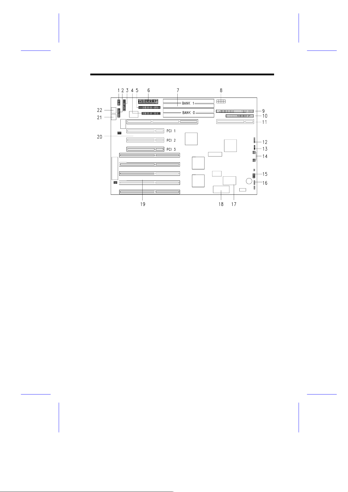
1 COM 2
2 COM 1
3 Parallel port interface
4 Diskette drive interface
5 IDE hard disk drive interface
6 Power connector 1
(200/350-watt)
7 SIMM sockets
8 Power connector 2 ( 350- watt)
9 Wide SCSI interface
10 Fast SCSI- 2 inter face
11 CPU board slot
12 Power LED connector
13 Hard disk LED connector
14 Fan connectors
15 Turbo/Reset connect or ( J23)
16 Speaker connector ( J24)
17 Real-time clock
18 BIOS
19 EISA expansion slots
20 PCI slots
21 PS/2 mouse connector
22 PS/2 keyboard connector
Figure 1-1 System Board Layout
System Board 1-3
Page 4

1.2 ESD Precautions
Always observe the foll owing precauti ons bef ore i nstall i ng any system
component:
1. Do not remove a board from its packaging unl ess you are ready
to install it.
2. Wear a wrist grounding strap before handling electronic
components. Wrist grounding straps are available at most
electronic component stores.
DO NOT attempt the procedures in the
following sect ions unles s y ou are confident of
your capability to per form them. Otherw ise,
ask a service tec hnic ian for assistance.
1.3 Upgrading the Memory
The system comes with a standard 8/16-MB mem ory, ex pandable up
to 128 MB, 192 MB, or 256 MB depending on t he type of CPU boar d
installed. You can upgrade the system memory by installing single
inline memory modules (SIMMs) into the SIMM sockets or by
changing the SIMMs f or a hi gher m em or y conf i gurat i on. T he f our 72pin SIMM sockets support 4-MB and 16-MB single-density as well as
8-MB and 32-MB double-density SIMMs.
1.3.1 Rules for Adding Memory
•
Always install SIMMs from the l owest bank f irst. F or exampl e,
use bank 0 before bank 1, bank 1 before bank 2, and so on.
•
Always remove SIMMs from the highest bank first. For exam ple,
bank 3 before bank 2, and so on.
•
Use only the same ty pe of SIMM in a given bank
•
You may combine different types of SIMMs for a particular
memor y conf igurati on as long as the SI MMs in each bank are of
the same type.
1-4 User’s Guide
Page 5
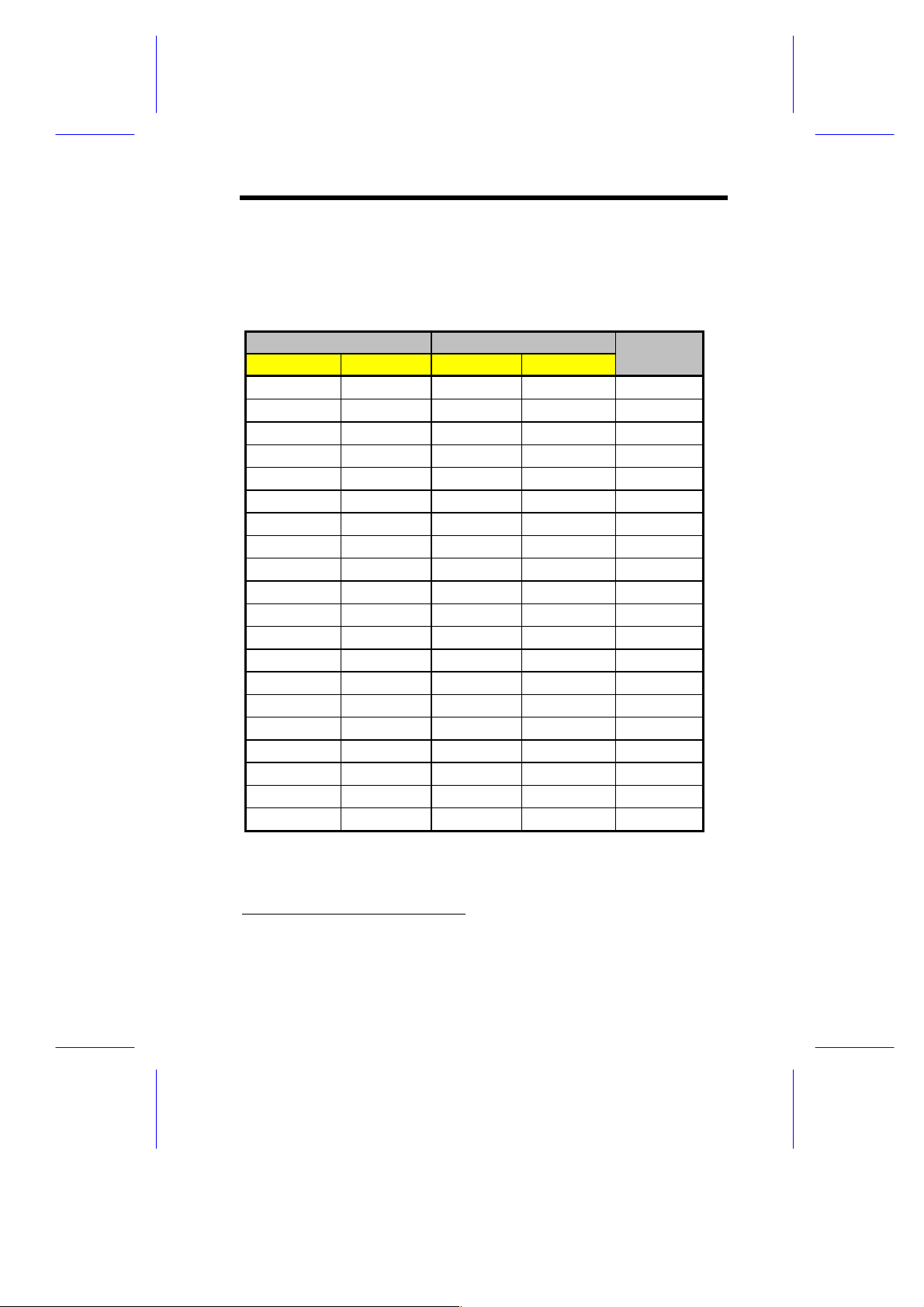
Table 1-1 li sts the avai lable m emory conf igurati ons when the system
uses either an IntelDX4, Pentium (5V), si ngle-Pentium ( 3.3V), or a
Pentium (3. 3V-ALI) CPU board.
Table 1-1 Memory Configurat ions
Bank 0 Bank 1 Total
S0 S1 S0 S1 Memory
4 MB 4 MB 8 MB
4 MB 4 MB 4 MB 4 MB 16 MB
8 MB 8 MB 16 MB
8 MB 8 MB 4 MB 4 MB 24 MB
4 MB 4 MB 8 MB 8 MB 24 MB
8 MB 8 MB 8 MB 8 MB 32 MB
16 MB 16 MB 32 MB
16 MB 16 MB 4 MB 4 MB 40 MB
4 MB 4 MB 16 MB 16 MB 40 MB
16 MB 16 MB 8 MB 8 MB 48 MB
8 MB 8 MB 16 MB 16 MB 48 MB
16 MB 16 MB 16 MB 16 MB 64 MB
32 MB 32 MB 64 MB
32 MB 32 MB 4 MB 4 MB 72 MB
4 MB 4 MB 32 MB 32 MB 72 MB
32 MB 32 MB 8 MB 8 MB 80 MB
8 MB 8 MB 32 MB 32 MB 80 MB
32 MB 32 MB 16 MB 16 MB 96 MB
16 MB 16 MB 32 MB 32 MB 96 MB
32 MB 32 MB 32 MB 32 MB 128 MB
1
* S0 and S1 stand for socket 0 and socket 1 respective ly.
1
When using the IntelDX4, Penti um (5V), single-Pentium (3.3V), a n d
Pentium (3.3V-ALI) CPU boards
System Board 1-5
Page 6

Models using the dual-Pentium (3.3V) CPU board, four additional
72-pin SIMM sockets are av ail able. W it h the additi onal sockets, you
can upgrade the mem ory up t o 256 MB using 32-MB SI MMs.
Table 1-2 lists some of the possible memory confi gurations when a
dual-Pentium (3.3V) CPU board is installed.
Banks 0 and 1 are on the system board;
banks 2 and 3 are on the dualPentium (3.3V) CP U boar d.
Table 1-2 Some Possible Memory Configurations when Using
the Dual-Pentium (3.3V) CPU Board
Bank 0 Bank 1 Bank 2 Bank 3 Total
S0 S1 S0 S1 S0 S1 S0 S1 Memory
4 MB 4 MB 8 MB
4 MB 4 MB 8 MB 8 MB 24 MB
4 MB 4 MB 8 MB 8 MB 16 MB 16 MB 56 MB
4 MB 4 MB 8 MB 8 MB 16 MB 16 MB 32 MB 32 MB 120 MB
4 MB 4 MB 4 MB 4 MB 16 MB
8 MB 8 MB 8 MB 8 MB 8 MB 8 MB 48 MB
16 MB 16 MB 16 MB 16 MB 32 MB 32 MB 32 MB 32 MB 192 MB
32 MB 32 MB 32 MB 32 MB 32 MB 32 MB 32 MB 32 MB 256 MB
* S0 and S1 stand for socket 0 and socket 1 respective ly.
The above configurations are only some of
the available memory combinations. You
can use other combinations as long as you
follow the rules when upgrading memory.
Refer to sect ion 1.3.1.
1-6 User’s Guide
Page 7

Models using the Pentium (3.3V-ECC) CPU board have two
additional 72-pi n SI MM socket s. With the addi t ional socket s, you can
upgrade the mem ory t o 192 MB using 32-MB SI MMs.
Table 1-3 lists some of the possible memory confi gurations when a
Pentium (3.3V-ECC) CPU board i s i nstalled.
Banks 0 and 1 are on the system board;
bank 2 is on the Pentium (3.3V-ECC) CPU
board.
Table 1-3 Some Possible Memory Configurations when Using
the Pentium (3. 3V - E CC) CP U B oar d
Bank 0 Bank 1 Bank 2 Total
S0 S1 S0 S1 S0 S1 Memory
4 MB 4 MB 8 MB
4 MB 4 MB 8 MB 8 MB 24 MB
4 MB 4 MB 8 MB 8 MB 16 MB 16 MB 56 MB
8 MB 8 MB 16 MB 16 MB 32 MB 32 MB 112 MB
4 MB 4 MB 4 MB 4 MB 4 MB 4 MB 24 MB
8 MB 8 MB 8 MB 8 MB 8 MB 8 MB 48 MB
16 MB 16 MB 16 MB 16 MB 16 MB 16 MB 96 MB
32 MB 32 MB 32 MB 32 MB 32 MB 32 MB 192 MB
* S0 and S1 stand for socket 0 and socket 1 respective ly.
The above configurations are only some of
the available memory combinations. You
can use other combinations as long as you
follow the rules when upgrading memory.
Refer to sect ion 1.3.1.
System Board 1-7
Page 8

1.3.2 Installing SIMMs
Read the ESD precautions in section 1.2
before proceeding.
Follow these steps to install a SIMM:
1. Slip a SIMM at a 45
o
angle into a socket with the component si de
faci ng down.
2. Gently push the S IMM to a v er tic al posi tion until t he pegs of t he
socket slip into t he hol es on the SIM M, and t he hol ding c li ps loc k
the SIMM into position. The SIMM should be at a 90
o
angle
when installed.
Hole
Peg
Clip
Figure 1-2 Installing a SIMM
Always install SIMMs starting with Bank 0
and in pairs. For example, for a total
memory of 8 MB, install two 4-MB SIMMs in
sockets 0 and 1 of B ank 0. You can not use
an 8-MB SIMM alone for an 8-MB memory.
1-8 User’s Guide
Page 9

1.3.3 Removing SIMMs
Follow these steps to remove SIMM s:
1. Press the holding clips on both sides of the SIMM outward to
release it.
2. Push the SIMM downward to a 45
3. Pull t he S IMM out of the socket.
o
angle.
1.3.4 Reconfiguring the System
Reconfi gur e the system after installing or r emovi ng S IMMs.
Follow these steps to reconfigure the system:
1. Reboot the system. A memory error message appears,
indicat ing t hat t he tot al m em ory does not m atc h t he v al ue stored
in CMOS.
2. Press
wrong memory c onfigurati on appear s.
3. Press
system boots with the new memory configuration.
--
twice to exit Setup and reboot the system. The
to run Setup. A message indicating a
System Board 1-9
Page 10

1.4 SCSI Feature
The system board feat ures a single-chi p SCSI host adapter that adds
SCSI I/O capability to the system. The chipset consists of an onboard
micr ocontrol ler, bus master interf ace cont roll er, and SCSI control lers.
A 50-pin Fast SCSI-2 inter face with 10 MB /s transfer rate and a 68pin W ide SCS I int erf ace that t ransfers at 20 MB/s also com e with the
board to accom modate the SCSI devices.
Before connec ti ng any SCS I device to t he 68-pi n i nt erf ace, connect a
Wide SCSI daughter board that has a compact 68-pin SCSI
connector. F igure 1-3 illustrates the daughter board.
1. 68-pin compact SCSI connector
2. 68-pin Wide SCSI connector (female)
Figure 1-3 Wide SCSI Daughter B oar d
1-10 User’s Guide
Page 11

1.4.1 Installing a Wide SCSI Daughter Board
Figure 1-4 shows how to install the Wide S CS I daughter board.
68-pin compact
Wide SCSI
daughter board
SCSI connector
68-pin Wide SCSI
connector (male)
Figure 1-4 Installing a Wide SCS I Daught er B oar d
1.4.2 Using the SCSI Feature
Follow these steps to use the SCSI feature:
1. Install a S CSI device i n the system and connect it t o the SCSI
interface on the system board (see Fi gur e 1- 1 for the locat ion).
2. Enter the BIOS utility to set the PCI slot parameters. See
Chapter 3 for details in setti ng the parameters.
3. Refer to the SCSI manual for more i nformation on using SCSI.
System Board 1-11
Page 12

1.5 Jumper Settings
You have t o change the jumper setti ngs on the system board when
you upgrade the CPU or reconfigure the system .
Follow these steps to change a j umper setting:
1. Remove the jumper c ap from the jumper.
2. Position t he jumper cap over the two pins for t he desi r ed setting.
3. Gently pr ess the cap over the pins.
Figure 1-5 shows the jum per locations on the system board.
Figure 1-5 System Board Jumper Locations
1-12 User’s Guide
Page 13

Table 1-4 lists the system board jumpers and their corresponding
settings.
Table 1-4 System Board Jumper Settings
Jumper Setting Function
JP1 1-2
JP2 1-2
JP3 1-2
JP4 1-2
JP5 Open
JP6 1-2
*
2-3
*
2-3
*
2-3
*
2-3
Closed
*
2-3
Acer BIOS
OEM BIOS
Password enabled
Password disabled
DMA request 1 (DREQ1)
DMA request 3 (DREQ3)
DMA acknowledge 1 (DACK1)
DMA acknowledge 3 (DACK3)
Reset button disabled
*
Reset button enabled
Audio to buzzer
Audio to speaker
1.6 Error Messages
Do not continue usi ng the computer if you receiv e an error m essage
of any type. Note the message and take corrective action. This
section describes the types of error messages and lists their
corresponding corrective measures.
There are two general t y pes of error messages:
•
Software
•
System
*
Default setting
System Board 1-13
Page 14

1.6.1 Software Error Messages
Software error messages are returned by your operating system or
application. These messages typically occur after you boot the
operating system or when you run your application. If you receive
this type of message, consult your application or operating system
manual for help.
1.6.2 System Error Messages
A system error message indicates a problem with the c omputer itself .
A message of this type normally appears during the power-on selftest, before the operati ng system prompt appears. Tabl e 1-5 li sts the
system error messages.
Table 1-5 System Error Messages
Message Action
CMOS Battery Error Replace the RTC chip or contact
CMOS Checksum Error Check the RTC chip and the
Displ ay Card Mismatch Run Setup
Diskette Drive Control ler Error or
Not Installed
Diskette Drive Error Diskette may be defective. If not,
Diskette Drive A Type Mismatch Run Setup and sele ct the proper
Diskette Drive B Type Mismatch Run Setup and sele ct the proper
Equipment Configuration Error Modify DRAM configuration to
Fixed Disk Controller Error Run Setup.
your dealer.
necessary jumper. If the battery is
still good, run Setup.
Check and connect the control
cable to the diskette controller.
replace the diskette drive.
drive type.
drive type.
agree with one of the options in
Tables 1-1, 1-2, and 1-3.
1-14 User’s Guide
Page 15

Table 1-5 System Error Messages (continued)
Message Action
Fixed Disk 0 Error Check all cable connections.
Fixed Disk 1 Error Check all cable connections.
Key board Error or No Key board
Connected
Keyb oard Interface Error Replace the keybo ard or cont act
Memory Error at:
MMMM:SSSS:OOO (W:XXXX,
R:YYYY)
where:
M: MB, S: Segment, O: Offest,
X/Y: write/read pattern
Memory Size Mismatch
CPU Clock M ismatch
Onboard Serial Port 1 Conflict Run Setup and disable the port.
Onboard Serial Port 2 Conflict Run Setup and disable the port.
Onboard Parallel Port Conflict Run Setup and disable the port.
Pointing Device Error Check an d connect pointing de vice.
Pointing Device Interface Error Replace the pointing device or
Press key to co ntinue or
--
Real Time Clock Error Check the RTC chip. If it is still
for Setup
Replace fixed disk.
Replace fixed disk.
Check and connect the keyboard to
the system unit.
your dealer.
Check SIMMs on the system
board. Contact your dealer.
Check the memory size based on
the system specifications. Check
the intern al cable connections. If
you are sure that connections and
valu es are co rrect, ignore the
message. If the message
reappears, ask for technical
assistance.
contact your dealer.
Press
good , run Setup. If not, replace the
RTC chip.
or --.
System Board 1-15
Page 16

1.6.3 Correcting Error Conditions
As a general rule, if an error m essage says "Press F1 t o conti nue," it
is caused by a confi guration probl em, which can be easily corrected.
An equipment malf unc tion is more l ikely to c ause a fatal error, i .e., an
error that causes com plete system failure.
Here are some corrective measures for error conditions:
1. Run Setup. You m ust know the correct configur ation v alues for
your system before you enter Setup, which is why you should
write them down when the system is correctly configured. An
incorrect configuration is a major cause of power-on error
messages, especially for a new system.
2. Remove the system cover, fol lowing the directions in the housing
install ation manual. Chec k that the jumper s on the system boar d
and any expansion boards are set corr ec tly.
3. If you cannot access a new disk, it m ay be because your disk is
not properly formatted. Format the disk first using the FDISK
and FORMAT c ommands.
4. Check that al l connectors and boards are secure.
If you go t hrough these steps and still receive an error message, the
cause may be an equipment malfunction.
If you are sure that your configuration values are correct and your
battery is in good condition, the problem may lie in a damaged or
defective chi p.
In either c ase, c ontact an authorized service center for assistance.
1-16 User’s Guide
 Loading...