

Acer ALTOS 600 User Manual

Altos 600 Series
User’s Guide

2

iii
Document
History
__________________________________________________________________________
EDITION PART NUMBER DATE
First Edition 49.AD255.001 September 2000
Copyright
Notice
__________________________________________________________________________
Trademarks
__________________________________________________________________________
Disclaimer
__________________________________________________________________________
Copyright © 2000 by Acer America Corporation. All rights reserved. No part of
this publication may be reproduced, transmitted, transcribed, stored in a retrieval
system, or translated into any language orcomputer language, in any form or by
any means, electronic, mechanical, magnetic, optical, chemical,manual or otherwise, without the prior written permission of Acer America Corporation.
Printed in U.S.A
Acer and the Acer logo are registered trademarks of Acer Incorporated.
Adaptec is a registered trademark of Adaptec, Inc.
Windows and Windows NT are registered trademarks of Microsoft Corporation.
Intel, Pentium, and LANDesk are registered trademarks of Intel Corporation.
Novell and NetWare are registered trademarks of Novell, Inc.
Other brand and product names are trademarks or registered trademarks of their
respective ho lders.
Acer and its suppliers make no representations or warranties, either expressed
or implied, with respect to the contents hereof and specifically disclaim any
warranties of merchantability or fitness for a particular purpose. Further, Acer
reserves the right to revise this publication and to make changes from time to
time in the contents hereof without obligation to notify any person of such revisions or changes. Acer reserves the right to make changes to the products described in this manual at any time and without notice.

iv
Warranty/L im it ation of Liability
Any software described in this manual is licensed “as is” and Acer and its suppliers disclaim any
and all warranties, express or implied, including but not limited to any warranty of non-infringement of third party rights, merchantability or fitness for a particular purpose. Acer does not warrant that the operation of the software will be uninterrupted or error free. Should the programs
prove defective, the buyer (and not Acer, its distributor, or its dealer) assumes the entire cost of
all necessary service, repair, and any incidental or consequential damages resulting from any defect in the software. Please see the Acer Limited Product Warranty for details of Acer’s limited
warranty on hardware products. IN NO EVENT SHALL ACER BE LIABLE FOR ANY INDIRECT
OR CONSEQUENTIAL DAMAGES, INCLUDING LOSS OF PROFITS OR DATA, EVEN IF
ACER HAS BEEN ADVISED OF THE POSSIBILITY OF SUCH DAMAGES.
Software License
Acer grants you a personal, non-transferable, non-exclusive license to use the software that accompanies your computer system only on a single computer. You may not (a) make copies of the
software except for making one (1) backup copy of the software which will also be subject to this
license, (b) reverse engineer, decompile, disassemble, translate or create derivative works based
upon the software, (c) export or re-export the software to any person or destination which is not
authorized to receive them under the export control laws and regulations of the United States, (d)
remove or alter in any way the copyright notices, or other proprietary legends that were on the
software as delivered to you or (e) sublicense or otherwise make the software available to third
parties. The software is the property of A cer or Acer’s s upplier a nd you do not have an d shall not
gain any proprietary interest in the software (including any modifications or copies made by or
for you) or any related intellectual property rights. Additional restrictions may apply to certain
software titles. Please refer to any software licenses that accompany such software for details.
The Acer Group has been implementing a policy to respect and protect legitimate intellectual
property rights. Acer firmly believes that only when each and every one of us abides by such policy, can this industry provide quality service to the general public.
Acer has become a member of the Technology Committee of the Pacific Basin Economic Council
which is encouraging the protection and enforcement of legitimate intellectual property rights
worldwide. Moreover, in order to ensure quality service to all of our customers, Acer includes an
operating system in Acer computer systems which is duly licensed by the legitimate proprietors
and produced with quality.
Acer commits itself and urges all of its customers to join the fight against intellectual property piracy wherever it may occur. Acer will pursue the enforcement of intellectual property rights and
will strive to fight against piracy.

Notices
FCC notice
This device has been tested and found to comply with the limits for a Class B
digital device pursuant to Part 15 of the FCC Rules. These limits are designed to
provide reasonable protection against harmful interference in a residential
installation. This device generates, uses, and can radiate radio frequency energy
and, if not installed and used in acc or da nce wit h the instructions, may cause
harmful interference to radio communications.
Howev e r, there is no guarantee that interference will not occur in a particular
installation. If this device does cause harmful interference to radio or television
reception, which can be determined by turning the device off and on, the user is
encouraged to try to correct the interference by one or more of the following
measures:
• Reorient or relocate the receiving antenna
• Increase the separation between the device and receiver
• Connect the device into an outlet on a circuit different from that to which the
receiver is connected
• Consult the dealer or an experienced radio/television technician for help
v
Notice: Shielded cables
All connections to other computing devices must be made using shielded cables to
maintain compliance with FCC regulations.
Notice: Peripheral devices
Only peripherals (input/ output devic es, termi nals, prin ters, etc.) certifie d to comply
with the Class B limits may be attached to this equipment. Operation with
noncertified peripherals is likely to result in interference to radio and TV reception.
Caution!
manufacturer could void the user’s authority, which is granted by the Federal
Communications Commission, to operate this computer.
Changes or modifications not expressly approved by the

vi
Use conditions
This part complies with Part 15 of the FCC Rules. Operation is subject to the
following two conditions: (1) this device may not cause harmful interference, and
(2) this device must accept any interference received, including interference that
may cause undesired operation.
Notice: Canadian users
This Class B digital apparatus meets all requirements of the Canadian InterferenceCausing Equipment Regulations.
Remarque à l’intention des utilisateurs canadiens
Cet appareil numérique de la classe B respected toutes les exigences du Règlement
sur le matériel brouilleur du Canada.
Important safety instructions
Read these instructions carefully. Save these instructions for future reference.
1. Follow all warnings and instructions marked on the pr oduct.
2. Unplug this product from the wall outlet before cleaning. Do not use liquid
cleaners or aerosol cleaners. Use a damp cloth for cleaning.
3. Do not use this product near water.
4. Do not place this product on an unstable cart, stand, or table. The product
may fall, causing serious damage to the product.
5. Slots and openings in the cabinet and the back or bottom are provided for
ventilation; to ensure reliable operation of the product and to protect it from
overheating, these openings must not be blocked or covered. The openings
should never be blocked by placing the product on a bed, sofa, rug, or other
similar surface. This product should never be placed near or over a radiator or
heat register, or in a built-in installation unless proper ventilation is provided.
6. This product should be operated from the type of power indicated on the
marking label. If you are not sure of the type of power av a ila ble, c onsult you r
dealer or local power company.
7. Do not allow anything to rest on the power cord. Do not locate this product
where persons will walk on t he cord.
8. If an extension cord is used with this product, make sure that the total ampere
rating of the equipment plugged into the exte n sion cord does no t exceed the
extension cord ampere rating. Also, make sure that the total rating of all
products plugged into the wall outlet does not exceed the fuse rating.

vii
9. Never push objects of any kind into this product through cabinet slots as they
may touch dangerous voltage points or short out parts that could result in a
fire or e lectric shock. Never s pill l i quid of any kind on the product.
10. Do not attempt to service this product yourself, as opening or removing
covers may expose you to dangerous voltage points or other risks. Refer all
servicing to qualified service personnel.
11. Unplug this product f rom the wall outlet and refer servici ng to qualified
service personnel under the following conditions:
a. When th e power cord or plug is damaged or frayed
b. If liquid has been spilled into the product
c. If the product has been exposed to rain or water
d. If the product does not operate normally when the operating instructions
are followed. Adjust only those controls that are cover ed by the
operating instructions since improper adju stment of other contro l s may
result in damage and will often require extensive work by a qualified
technician to restore the pr oduct to normal condition.
e. If the product has been dropped or the cabinet has been damaged
f. If the product exhibits a distinct change in performance, indicating a
need for service.
12. Replace the battery with the same type as the product's battery we
recommend. Use of another battery may present a risk of fire or explosion.
Refer battery replacement to a qualified serviceman.
13. Warning! Batter ies m ay e xplode if not hand led prope rly. Do not disass emble
or dispose of them in fire. Ke ep them away from children and dispose of used
batteries promptly.
14. Use only the proper type of power supply cord set (provided in your
accessories box) for this unit. It should be a detachable typ e: UL listed/CSA
certified, type SPT-2, rated 7A 125V minimum, VDE approved or its
equiva lent. Maximum length is 15 feet (4.6 meters).
Laser compliance statement
The CD-ROM drive in this computer is a laser product. The CD-ROM drive’
classification la bel (shown below) is located on the drive.
CLASS 1 LASER PRODUCT
CAUTION:
EXPOSURE TO BEAM.
INVISIBLE LASER RADIATION WHEN OPEN. AVOID

viii
APPAREIL A LASER DE CLASSE 1 PRODUIT
LASERATTENTION:
CAS D’OUVERTURE. EVITTER TOUTE EXPOSITION AUX RAYONS.
LASER KLASSE 1
VORSICHT:
GEÖFFNET, NICHT DEM STRAHLL AUSSETZEN
PRODUCTO LÁSER DE LA CLASE I
ADVERTENCIA:
EVITE EXPONERSE A LOS RAYOS.
UNSICHTBARE LASERSTRAHLUNG, WENN ABDECKUNG
RADIATION DU FAISCEAU LASER INVISIBLE EN
RADIACIÓN LÁSER INVISIBLE AL SER ABIERTO.
ADVARSEL:
VARO!
VARNING:
TUIJOTA SÅTEESEENSTIRRA EJ IN I STRÅLEN
VARNING:
IN I STRÅLEN
ADVARSEL:
STRÅLEN
LASERSTRÅLING VEDÅBNING SE IKKE IND I STRÅLEN
LAVATTAESSA OLET ALTTINA LASERSÅTEILYLLE.
LASERSTRÅLNING NÅR DENNA DEL ÅR ÖPPNAD ÅLÅ
LASERSTRÅLNING NAR DENNA DEL ÅR ÖPP NADSTIRRA EJ
LASERSTRÅLING NAR DEKSEL ÅPNESSTIRR IKKE INN I
Lithium battery statement
CAUTION
Danger of explosion if battery is incorrectly replaced. Replace only with the same
or equivalent type recommended by the manufacturer. Discard used batteries
according to t he manufacturer’s instructions.
ADVARSEL!
Lithiumbatteri - Eksplosionsfare ved fejlagtig håndtering. Udskiftning må kun ske
med batteri af samme fabrikat og type. Léver det brugte batteri tilbage til
leverandøren.

ADVARSEL
Eksplosjonsfare ved feilaktig skifte av batteri. Benytt samme batteritype eller en
tilsvarende type anbefalt av apparatfabrikanten. Brukte batterier kasseres i
henhold til fabrikantens instruksjoner.
VARNING
Explosionsfara vid felaktigt batteribyte. Anvãnd samma batterityp eller en
ekvivalent typ som rekommenderas av apparattillverkaren. Kassera anvãnt batteri
enligt fabrikantens instruktion.
VARO ITUS
Päristo voi räjähtää, jos se on virheellisesti asennettu. Vaihda paristo ainoastaan
laitevalmistajan suosittelemaan tyyppiin. Hävitä käytetty paristo valmistajan
ohjeiden mukaisesti.
VORSICHT!
Explosionsgefahr bei unsachg emäßen Austausch der Batterie Ersatz nur durch
denselben ode r einem vom Hersteller empfohlenem ähnlichen Typ. Entsorgung
gebrauchter Batterien nach Angaben des Herstellers.
ix

x

Getting Started 1
Overview 1
Processors 2
Memory 2
System chipsets 2
Apollo Pro 133A chipset 2
SCSI subsystem 3
LAN subsystem 3
Expansion slots 3
AGP bus 3
PCI bus 4
Hardware manageme nt supp o rt 4
Features summary 5
Preinstallation requirements 6
Selecting a site 6
Basic connections 7
Connecting the keyboard 7
Connecting the mouse 8
Connecting the VGA monitor 8
Connecting to the network 9
Connecting the power cable 9
System startup 10
Power-on problems 11
Connecting options 12
Printer 12
USB devices 13
Contents
System Tour 15
External and internal structure 16
Front panel 16
Rear panel 17
Internal components 18
System board layout 20
BPL5-M backplane board (BPL5-M) (optional) 23
Jumpers and connectors 23
Keyboard 25
Cursor keys 25
Lock keys 25
Disk drives 27
3.5-inch floppy disk drive 27
CD-ROM drive 27
To insert a CD into your system’s CD-ROM drive: 28

To take care of your CDs: 28
Front Panel Connectors 29
Memory Configurations 30
Upgrading Your System 31
Installation precautions 31
ESD precautions 31
Preinstallation instructions 32
Post-installation instructions 32
Opening your system 33
Opening the front panel door 33
Removing the fro n t panel door 33
Opening the side panel 33
Installing and r emoving storage devices 35
Replacing a 3 .5 - inch storage device 35
Installing a BPL5-M hot-swap cage 36
System board connector cable 38
Installing and removing a BPL5-M hard disk drive tray 39
Replacing a 5.25-inch storage device (optional) 40
Installing and removing the CPU 42
Installing a CPU 42
Removing a CPU 43
Installing an d r emoving memory modules 44
Reconfiguring the system 45
Installing exp ansi on cards 46
Hot-swappable redundant power supply module (optional) 47
Installing an external redundant system fan (optional) 49
BIOS Utility 51
Introduction 51
Entering Setup 52
System information 54
Product infor mation 56
Disk drives 57
IDE channel type 59
Onboard peripherals 62
Power management 65
Boot options 6 8
Date and time 71
System security 72
Supervisor password 7 4
Setting and changing the password 74

Removing a password 75
User Password 75
Setting and changing the password 75
Removing a Password 76
IPMI (Intelligent Platform Management Interface) configuration 77
RDM (Remote Diagnostic Manager) configuration 79
Advanced options 82
Memory/Cache options 83
PnP/PCI options 84
Load default settings 87
Abort settings change 88
Exit Setup 89
SCSISelect Utility 91
Overview 91
Default Values 91
When to Use the SCSISelect Utility 92
Running the SCSISelect Utility 93
SCSISelect Utility Options 93
Configure/View Host Adapter Settings Menu 93
Boot Device Options 94
Advanced Configuration Options 97
SCSI Disk Utilities 98
Configuring Multiple SCSI Controllers 100
SCSI Troubleshooting Checklist 101
BIOS Startup Messages 101
Device connected, but not ready 102
Start unit request failed 102
Disk Drive Configuration Problems 103

xiv

1
Chapter 1
Getting Started
The Altos 600 is a powerful dual-processor system loaded wit h a host of new and
innovative features. The system offers a new standard for flexible productivity
ideal for local or wide area networks and multiuser server environments.
Overview
The Altos 600 is a PCI bus based dual-processor system board built on an extended
ATX baseboard. It comes with a dual FC-PGA (Flip-Chip Pin-Grip Array)
processor socket utilizing an Intel
Apollo Pro 133A chip set. The system board also integrates the Intel® 82559 10/
100 Mbps PCI Ethernet chipset that supports WOL (Wake on LAN) for better
remote site management.
®
Pentium® III processor integrated with the
For expanda bility, the system board includes one A GP (Acceler ated Graph ics Port)
bus, five PCI bus slots and three DIMM sockets that allow memory installation to a
maximum of 1.5 GB using three 512-MB SDRAM (synchronous DRAM)
DIMMs.
For connectivity, the system board supports two USB (Universal Serial Bus)
connectors and other standard features such as two UAR T NS16C550 serial ports,
one enhanced parallel port with Enhanced Parallel Port (EPP)/Extended
Capabilities Port (ECP) support, a diskette drive interface, and two embedded hard
disk interfaces.
The system is compatible with current IBM PC-DOS, Novell NetWare 5.1, SCO
OpenServer 5.0.6, SCO UnixWare 7.1.1, Red Hat Linux 6.2, Caldera OpenLinux
eServer 2.3,Windows NT 4.0, and Windows 2000 Server.

2
Chapter 1 Getting Started
Processors
The Pentium III processor implements Dynamic Execution performance, a multitransaction system bus, and Intel MMX media enhancement technology. Also, it
offers Streaming SIMD (Single Instruction Multiple Data) Extensions - 70 ne
instructions enabling advanced imaging, 3D, streaming audio and video, and
speech recognition applications. The Pentium III processor delivers higher
performance than the previous Pentium processor while maintaining binary
compatibility with all previous Intel Architecture processors.
This system board currently supports 100 or 133 MHz GTL+ host bus frequencies
for one Pentium III processor r unni ng at 667 MHz, 733 MHz, 800 MHz, or 866
MHz.
Memory
The three DIMM sockets on board al low memory upgrade to a maximum of 1.5
GB using three 512-MB SDRAM (synchronous DRAM) DIMMs. For data
integrity, the default setting of the ECC (error-correcting code) function of the
memory system in BIOS is enabled. See “Memory/Cache options” on page 83 for
more on this BIOS setting.
Note:
The SDRAM should work under 3.3 volts only; 5-volt memory devices
are not supported.
The system board supports both 100 and 133 MHz SDRAMs; 66 MHz SDRAMs
are not supported.
System chipsets
Apollo Pro 133A chipset
The Apollo Pro 133A chipset was specifically designed to meet the needs of high
performance systems. It consis ts of two components: VT82C69 4X (north bridge)
and VT82C686A (south bridge).
• VT82C694X (north bridge) provides the host interface, memory system
control interface, PC I interface, and AGP interface to boost graphics
performance.

• VT82C686A (south bridge) integrates super I/O functions like keyboard and
mouse interface, floppy disk controller, advanced digital data separator, two
compatible serial ports (UARTs), one parallel port, on-chip 12 mA AT bus
drivers, one floppy direct drive support, and Intelligent Power Management
support.
SCSI subsystem
The dual-channel AIC-7899 single-chip host ad apter delivers Ultra160/m SCSI
data transfer rates which double the Ultra-2 SCSI data transfer bandwidth of up to
160 MByte/sec. It supports up to 15 devices on a 12-meter cable (or 25 meters in a
point-to-point configuration ), making it ideal for both clustering and RAID
configurations.
LAN subsystem
Another cost-effective feature for network s olutions is the integration of Intel’s
82559 10/100 Mbps Fast Ethernet controller which supports:
• Advanced Configuration and Power Interface (ACPI) based power
management capability
• wake on Magic Packet
• wake on interesting packet
• advanced System Management Bus (SMBUS) based manageability
• Wired for Management (WfM) 2.0 compliance
• IP checksum assist
• PCI 2.2 compliance
• PC 98 and PC 99 compliance
3
Expansion slots
AGP bus
AGP is solely developed for the purpose of supporting 3D graphic applications. It
has a 32-bit wide channel that runs at 66 MHz, which translates into a total
bandwidth of 266 MBps. This is twice the bandwidth of PCI buses (133 MBps).

4
AGP also accesses the main memory directly allowing 3D textures to be stored in
main memory rather than video memory.
Chapter 1 Getting Started
PCI bus
The system board has five PCI slots that support 32-bit/33 MHz PCI devices. The
PCI bus is the key interface that communicates between the north and the south
bridge.
Hardware management support
The system board supports a po w er-management function that confor ms to the
power-saving standards of the U.S. Environmental Protection Agency (EPA)
Energy Star program. It also offers Plug-and-Play which helps save users from
configuration problems, thus making the system more user-friendly.
Additional features include hardware support for ASM (Advanced System
Manager) and RDM (Rem ote Dia gno st ic Manager). ASM detects problems in the
CPU thermal condition, CPU working voltage detection (±12V/±5V/3.3V/1.5V),
and PCI bus utilization calculation. It also detects if the CPU fan or the chas sis fan
malfunctions. Meanwhile, RDM allo ws execution of the RDM diagnostic program
from a remote RDM station to fix detected problems or to reboot the system.

Features summary
The main board has the following major components :
• Utilizes a FC-PGA (Flip-Ch ip Pin-Grip Array) dual socket that su pports a
• Apollo Pro 133A chipset which consists of two components: VT82C694X
• Onboard 10/100 Mb/s Intel 82559 LAN chip that supports WOL
• Adaptec
• Channel A - one 68-pin ULTRA 160/m SCSI connector
• Channel B - one 68-pin ULTRA 160/m SCSI connector
• Three DIMM sockets that accept 64-, 128-, 256-, and 512-MB SDRAMs with
• One AGP bus and five PCI bus slots
• System clock/calendar with battery backup
• IDE disk drive interfaces
• Super I/O chipset
• Auxiliary power connector for 280-watts SPS and 337W (1+1) Redundant
• Advanced System Manager (ASM)
• External ports:
• USB connectors • RJ-45 jack
• PS/2-compati b l e keyboard port • Parallel port
• PS/2-com pat ib le mouse port • Serial ports 1 and 2
Pentium
(north bridge) and VT82C686A (south bridge)
a maximum memory upgrade of 1.5 GB
SPS
III processor running at 667, 733, 800, or 866 MHz
®
AIC-7899 Dual Channel SCSI controller chipset supports:
5

6
Chapter 1 Getting Started
Preinstallation requirements
Selecting a site
Before unpacking and installing the system, select a suitable site for the system for
maximum efficiency. Consider the following factors when choosi ng a site for the
system:
• Near a grounded power outlet
• Clean and dust-free
• Sturdy surface free from vibration
• Well-ventilated and away from sources of heat
• Secluded from electromagnetic fields produced by electrical devices such as
air conditioners, radio and TV transmitters, etc.
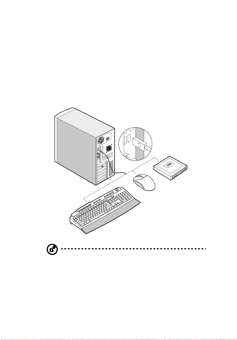
Basic connections
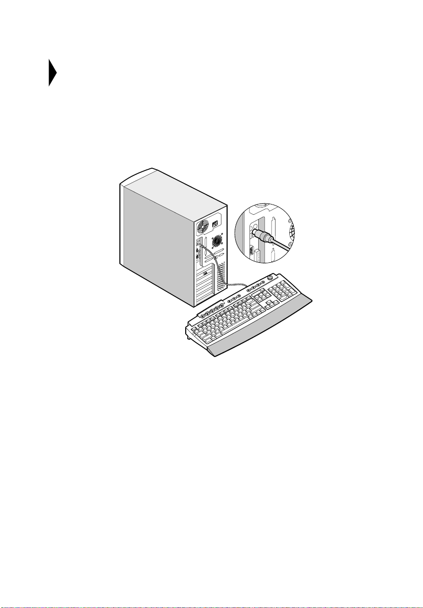
The system unit, keyboard, mouse, and monitor constitute the basic system.
Before connecting any other peripherals, connect these peripheral s first to test if
the system is running properly.
Connecting the keyboard
7
8
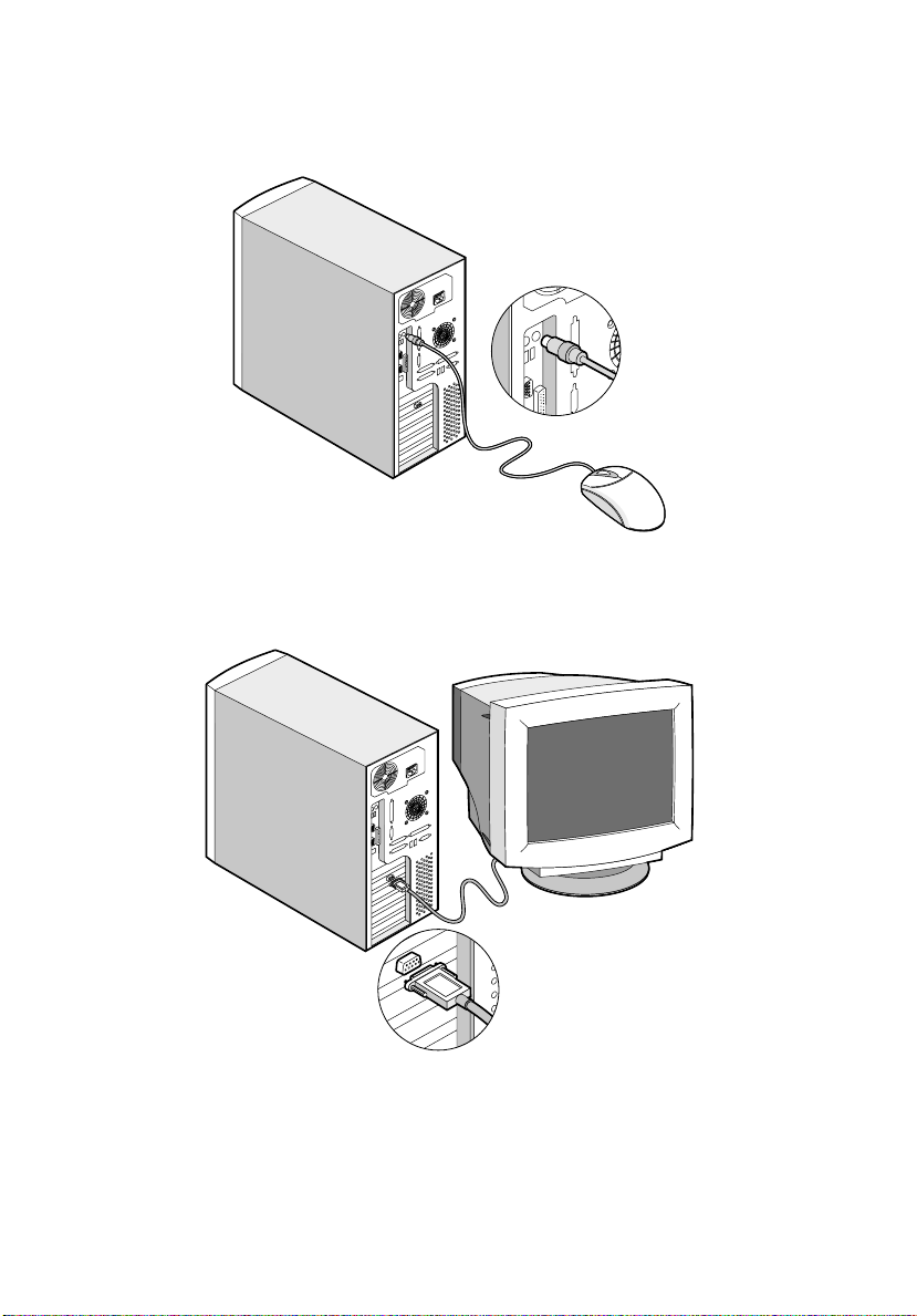
Connecting the mouse
Connecting the VGA monitor
Chapter 1 Getting Started
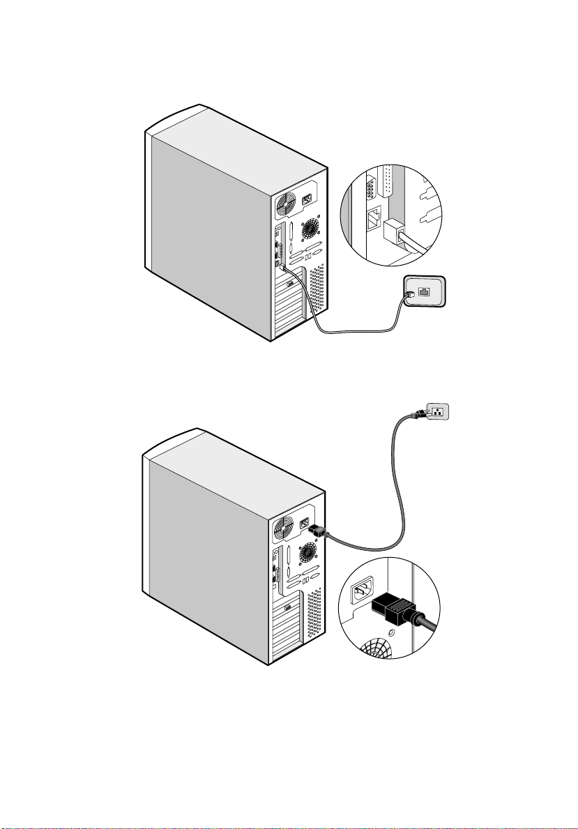
Connecting to the network
Connecting the power cable
9

10
Chapter 1 Getting Started
System startup
After making sure that you have set up the system properly and connected all the
required cabl es, y ou may now apply power to the system.
To power on the system:
1. Turn on the power switch to activate the power supply
2. Open the front panel door and press the On/Off button. The system starts up
and displays a welcome message. After that, a series of power-on self-test
(POST) messages appears. The POST messages indicate if the system is
running well or not.
Note:
If the system does not turn on or boot after pressing the On/Off button,
go to the next section for the possible causes o f the boot failure.
Aside from the self-test messages, you can determine if the system is in good
condition by checking if the following occurred:
• Power indicator LED on the fr on t bez el li ghts up (green)
• Power, Num Lock, and Caps Lock LED indicators on the keyboard light up
• Power supply power LED located at the back of the system lights up (green)

Power-on problems
If the system does not boot after you have applied power, check the following
factors that might have caused the boot failure.
• The external power cable may be loosely connected.
Check the power cable connection from the power source to the power socket
on the rear panel. Make sure that each cable is properly connected to each
power supply.
• No power comes from the grounded power outlet.
Have an electrician check your power outlet.
• Loose or improperly connected internal power cables.
Check the internal cable connections. If you are not confident that you can
perform this step, ask a qualified technician to help you.
11
Warning!
outlet before performing this task.
Note:
fails to boot, ask your dealer or a qualified technician for assistance.
Make sure all power cords are disconnected from the electrical
If you have gone through the preceding actions and the system still
12
Chapter 1 Getting Started
Connecting options
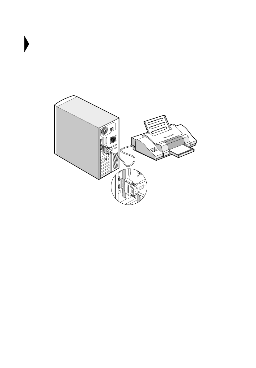
Printer
T o co nne ct a printer, plug the pri nter cable into th e parallel port located on the rear
panel of your system.
13
USB devices
Universal Serial Bus (USB) is a serial bus design that is capable of cascading low/medium-speed peripherals (less than 12 Mbps) such as a keyboard, mouse,
joystick, scanner, printer and modem. With U SB, complex cable connections can
be eliminated.
Your system comes with two USB ports. These ports allow you to connect
additional serial devices to your system without using up its system resources.
To connect a USB device, simply plug the device cable into one of the USB ports
located at the rear panel of your system.
Note:
Most USB devices have a built-in USB port which allows you to
daisy-chain other devices.

14
Chapter 1 Getting Started

Chapter 2
System Tour
This chapter discusses the features and components of your computer.
15
16
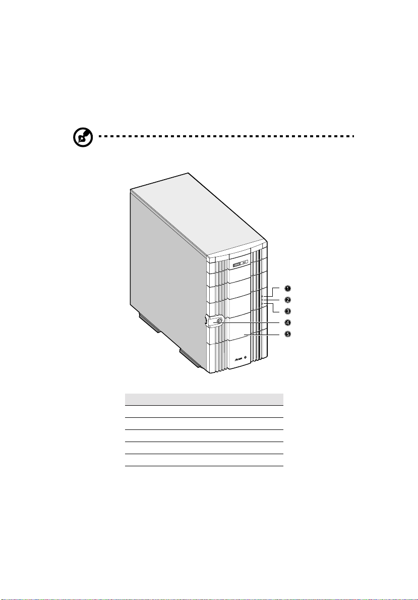
External and internal structure
Front panel
Note:
One pair of system keys are hung inside the front panel door.
Additional duplicate keys can be found at the back of the system.
Chapter 2 System Tour
No. Item
1Power LED 2 Hard disk LED 3 System status LED 4 Keylock 5 Front panel
 Loading...