

Page 1

AcerAltos 3102RSAcerAltos 3102RS
Ultra-SCSI to Ultra-SCSI RAID Controller
User’s Guide
Page 2

CopyrightCopyright
Copyright 1998 by Acer Inc. All rights reserved. No part of this
publication may be reproduced, transmitted, transcribed, stored in a
retrieval system, or translated into any language or computer
language, in any form or by any means, electronic, mechanical,
magnetic, optical, chemical, manual or otherwise, without the prior
written permission of this company.
DisclaimerDisclaimer
This company makes no representations or warranties, either
expressed or implied, with respect to the contents hereof and
specifically disclaims any warranties, merchantability or fitness for any
particular purpose. Any software described in this manual is sold or
licensed "as is". Should the programs prove defective following their
purchase, the buyer (and not this company, its distributor, or its dealer)
assumes the entire cost of all necessary servicing, repair, and any
incidental or consequential damages resulting from any defect in the
software. Further, this company reserves the right to revise this
publication and to make changes from time to time in the contents
hereof without obligation to notify any person of such revision or
changes.
ii
Page 3

FCC Class B Radio FrequencyFCC Class B Radio Frequency
Interference StatementInterference Statement
Note:
This equipment has been tested and found to comply with the limits for
a Class B digital device, pursuant to Part 15 of FCC Rules. These
limits are designed to provide reasonable protection against harmful
interference in a residential installation. This equipment generates,
uses, and can radiate radio frequency energy and, if not installed and
used in accordance with the instructions, may cause harmful
interference to radio communications. However, there is no guarantee
that interference will not occur in a particular installation. If this
equipment does cause harmful interference to radio or television
reception, which can be determined by turning the equipment off and
on, the user is encouraged to try to correct the interference by one or
more of the following measures:
1. Reorient or relocate the receiving antenna.
2. Increase the separation between the equipment and receiver.
3. Connect the equipment into an outlet on a circuit different from
that to which the receiver is connected.
4. Consult the dealer or an experienced radio/television technician
for help.
Notice 1:
The changes or modifications not expressly approved by the party
responsible for compliance could void the user's authority to operate
the equipment.
Notice 2:
Shielded interface cables, if any, must be used in order to comply with
the emission limits.
iii
Page 4

Table of ContentsTable of Contents
Chapter 1 Introduction ..................................................1
Chapter 2 Features.........................................................3
Chapter 3 Functional Description.................................7
RAID Management..........................................................................7
What are the RAID levels?.................................................7
NRAID Disk Spanning...................................................8
JBOD Single Drive Control............................................9
RAID 0 Disk Stripping....................................................9
RAID 1 Disk Mirroring .................................................10
RAID (0+1) Disk Striping with Mirroring ......................11
RAID 3 Disk Striping with Dedicated Parity Disk.........12
RAID 5 Striping with Interspersed Parity.....................13
Drive Failure Management............................................................ 14
Global and Local Spare Drive...........................................14
Identifying Drives..............................................................16
Automatic Rebuild and Manual Rebuild ...........................18
Automatic Rebuild.......................................................18
Manual Rebuild ...........................................................19
Concurrent Rebuild in RAID (0+1)....................................20
Disk Array Parameters ..................................................................21
Rebuild Priority .................................................................21
Verify-after-Write..............................................................21
Cache Parameters.........................................................................23
iv
Page 5

Optimization for Sequential or Random I/O......................23
Drive-Side SCSI Parameters .........................................................24
SCSI Motor Spin-up..........................................................24
SCSI Reset at Power Up...................................................24
Disk Access Delay Time...................................................25
SAF-TE Enclosure Management ...................................................26
What is SAF-TE?..............................................................26
How Does SAF-TE work?.................................................26
Dynamic Logical Drive Expansion..................................................27
What Is It and How Does It Work? ...................................27
Two Modes of Dynamic Logical Drive Expansion.............27
Example: RAID Expansion in Windows NT
Server ................................................................30
Chapter 4 Hardware Installation................................. 39
Locations of the Parts ....................................................................39
Front View ......................................................................39
Rear View of the Main Board............................................40
Top View of the Main Board..............................................41
Top View of the Daughter Board (AA-9073UWS).............42
Top View of the Daughter Board (AA-9072UWD) ............42
Top View of the Daughter Board (AA-9073U2).................43
Installing DRAM SIMM...................................................................44
Installing the SCSI Channel Upgrade Daughter Board..................45
Battery Backup...............................................................................47
Power Connection..........................................................................50
Serial Port Connection and Set-Up................................................51
Basic Operational setup.................................................................53
v
Page 6

In-band SCSI.................................................................................55
What is it and why do you need it?...................................55
How Do You Configure the Acer RAID Manager
to Use In-band SCSI? .......................................56
RAID Controller Adjustments......................................56
Example: Settings for Windows NT 4.0 ......................58
Using In-band SCSI in Acer RAID Manager..................... 60
Local Connection — SNMP Not Required ..................60
Remote Connection — SNMP Required.....................60
Chapter 5 Quick Setup.................................................67
Front Panel....................................................................................67
RS-232 Terminal Interface ............................................................ 69
Chapter 6 Configuring RAID........................................71
Starting to Build a RAID System Drive ..........................................71
How the RAID Controller Works?..................................................73
SCSI Channel, SCSI ID and LUN.....................................73
Understanding Step by Step............................................. 74
Chapter 7 General Front Panel Operation..................77
Understanding the Information on the LCD................................... 77
The Initial Screen..............................................................77
Logical Drive Status..........................................................78
SCSI Drive Status.............................................................79
SCSI Channel Status........................................................80
Viewing and Editing Logical Drives................................................82
Creating a Logical Drive...................................................82
vi
Page 7

Viewing Logical Drives and Drive Members......................84
Deleting a Logical Drive....................................................84
Partitioning a Logical Drive ...............................................85
Deleting a Partition of a Logical Drive...............................86
Assigning a Logical Drive Name.......................................87
Rebuilding a Logical Drive ................................................88
Viewing and Editing Host LUNs .....................................................90
Mapping a Logical Drive to a Host LUN............................90
Viewing and Deleting LUN Mappings................................91
Pass-through SCSI Commands........................................91
Viewing and Editing SCSI Drives...................................................93
Scanning New SCSI Drive................................................93
Viewing Drive Information.................................................94
Adding a Local Spare Drive ..............................................95
Adding Global Spare Drive................................................96
Identifying a Drive .............................................................96
Deleting Spare Drive (Global / Local Spare Drive)............97
SCSI Drives Utilities..........................................................98
SCSI Drive Low-level Format......................................98
SCSI Drive Read/Write Test.......................................99
Viewing and Editing SCSI Channels............................................100
Viewing and Redefining a Channel Mode.......................100
Setting a SCSI Channel’s ID / Host Channel..................101
Viewing a SCSI Channel’s ID ...................................101
Setting a SCSI Channel’s Primary ID / Drive
Channel............................................................103
Setting a SCSI Channel’s Secondary ID / Drive
Channel............................................................104
vii
Page 8

Setting a SCSI Channel’s Terminator ............................105
Setting the Transfer Speed ............................................106
Setting the Transfer Width .............................................107
Viewing and Editing a SCSI Target / Drive
Channel...........................................................108
Slot Number ..............................................................108
Maximum Synchronous Transfer Clock....................108
Maximum Transfer Width..........................................109
Parity Check..............................................................109
Disconnecting Support..............................................110
Maximum Tag Count.................................................110
Restoring the Default Setting ....................................111
Viewing and Editing Configuration Parameters...........................112
Communication Parameters........................................... 112
Caching Parameters.......................................................112
Write-Back Cache Enable/Disable............................112
Optimization for Sequential / Optimization for
Random ...............................................................113
viii
Host-side SCSI Parameters...........................................113
Maximum Queued I/O Count ....................................114
LUNs per Host SCSI ID.............................................114
Drive-side SCSI Parameters.......................................... 114
SCSI Motor Spin-Up..................................................115
SCSI Reset at Power-Up...........................................115
Disk Access Delay Time ...........................................116
Tag Command Queuing............................................116
SAF-TE Enclosure Monitoring...................................117
Page 9

Detection of Drive Hot Swap Followed by Auto
Rebuild.................................................................117
Idle Drive Failure Detection.......................................118
Disk Array Parameters....................................................119
Rebuilding Priority.....................................................119
Verification on Writes................................................ 119
Controller Parameters.....................................................121
Controller Name........................................................121
Viewing and Editing Peripheral Devices.......................................122
System Functions.........................................................................123
Mute Beeper....................................................................123
Changing the Password..................................................123
Resetting the Controller ..................................................124
Viewing System Information.........................................................125
Viewing and Editing Event Logs...................................................126
Chapter 8 RS-232C Terminal Interface .................... 127
Understanding the Information on the Screen .............................127
The Initial Screen............................................................127
Main Menu ....................................................................128
Logical Drive’s Status......................................................129
SCSI Drive’s Status.........................................................130
SCSI Channel’s Status....................................................132
Viewing the Current Setting of Each Function ................134
Viewing and Editing Logical Drives..............................................136
Creating a Logical Drive..................................................136
Viewing Logical Drives and Drive Members....................139
ix
Page 10

Deleting a Logical Drive..................................................140
Partitioning a Logical Drive.............................................140
Deleting a Partition of a Logical Drive ............................141
Assigning a Logical Drive Name.....................................142
Rebuilding Logical Drive.................................................143
Viewing and Editing Host LUNs...................................................145
Mapping a Logical Drive to a Host LUN .........................145
Viewing and Deleting the LUN Mappings.......................148
Viewing and Editing SCSI Drives.................................................150
Scanning a New SCSI Drive...........................................150
Viewing Drive Information...............................................151
Adding a Local Spare Drive............................................152
Adding a Global Spare Drive..........................................153
Identifying a Drive...........................................................153
Deleting a Spare Drive (Global / Local Spare
Drive)...............................................................154
Viewing and Editing SCSI Channels............................................155
Redefining a Channel Mode........................................... 155
Viewing and Editing a SCSI ID / Host Channel .............. 156
Adding a SCSI ID......................................................157
Deleting a SCSI ID....................................................157
Setting a Primary Controller’s SCSI ID / Drive
Channel...........................................................158
Setting a Secondary Controller’s SCSI ID / Drive
Channel...........................................................160
Setting a SCSI Channel’s Terminator ............................161
Setting a Transfer Speed ...............................................162
Setting a Transfer Width ................................................163
x
Page 11

Viewing and Editing SCSI Target / Drive Channel..........164
Slot Number..............................................................165
Maximum Synchronize Transfer Clock.....................165
Maximum Transfer Width.........................................166
Parity Check..............................................................166
Disconnecting Support.............................................. 167
Maximum Tag Count ................................................ 167
Restoring the Default Setting....................................168
Viewing and Editing Configuration Parameters............................169
Communication Parameters...........................................169
Caching Parameters.......................................................170
Write-Back Cache Enable/Disable ...........................170
Optimization for Random or Sequential I/O.............. 171
Host-side SCSI Parameters............................................172
Maximum Queued I/O Count....................................172
LUNs per Host SCSI ID ..................................................172
Drive-side SCSI Parameters...........................................173
SCSI Motor Spin-Up .................................................173
SCSI Reset at Power-Up..........................................174
Disk Access Delay Time........................................... 174
Maximum Tag Count ................................................ 175
Disk Array Parameters....................................................176
Rebuild Priority.......................................................... 176
Verification On Writes...............................................177
Controller Parameters.....................................................178
Controller Name........................................................178
xi
Page 12

System Functions........................................................................179
Mute Beeper................................................................... 179
Change Password..........................................................180
Changing the Password............................................181
Setting a New Password...........................................181
Disabling the Password.............................................182
Reset Controller..............................................................182
Viewing System Information........................................................183
Chapter 9 Redundant Controller............................185
Before You Begin.........................................................................185
What Is Redundant Controller? Why The Need For
Redundant Controller?.........................................185
Write-Back Cache: Enabled or Disabled?.................185
What are Primary controller and Secondary
controller? ............................................................186
When should I choose Primary, Secondary or
Autocfg mode?.....................................................186
Quick Start ................................................................187
Setting Up Redundant Controllers...............................................188
Example of Redundant Controllers ................................188
Cables and Connections ................................................189
Connecting the Redundant Controller Cable.............189
Connecting the Controllers to the Terminal
Interface...............................................................190
Connecting the SCSI Cable to the Host Computer...190
Connecting the SCSI Cables to the Hard Drives.......191
Setting the Controllers using the Front Panel.................192
xii
Page 13

Redundant Configuration using Automatic Setting...192
Redundant Configuration Using Manual Setting....... 193
Starting-up the Redundant Controllers ..................... 195
Assigning Logical Drives to the Secondary
Controller.............................................................196
When One of the Controller Fails.................................................198
What will happen when the one of the controllers
fails? .................................................................... 198
When and How is the Failed Controller Replaced?.. 198
Chapter 10 Redundant Host, Multiple Host............. 201
Redundant Host...........................................................................201
Multiple Host.................................................................................202
Chapter 11 Remote Administration.......................... 203
Acer RAID Manager Using SNMP Service .................................204
How to Establish Connection through SNMP? .........204
Remote Terminal Emulation Using PPP+Telnet..........................206
Hardware Connection...............................................206
Baud Rate Settings................................................... 207
Enable Terminal Emulation.......................................208
Setting PPP ID, PPP Password................................ 208
Data Routing Through PPP, Data Routing Direct to
Port......................................................................210
Establish Connection Between the Host Computer
and AA-3102RS................................................... 211
Connect Telnet to the Controller’s IP from the Client
Computer.............................................................212
xiii
Page 14

Remote Terminal Emulation Using Modem.................................213
Hardware Connection for AA-3102RS ......................214
Setting AA-3102RS using the RS-232C Terminal
Interface...............................................................214
Configuring the Modem Port.....................................215
Modem Initialization Command.................................216
Modem Operating Modes..........................................216
Sending Default Init command and Custom Init
command - “Append to Default”...........................217
Initializing Modem......................................................217
Baud rate, Data Routing and Enable Terminal
Emulation.............................................................218
Establish the Connection from the Remote Terminal219
How do you know the modem is connected?............219
Setting AA-3102RS Using the Front Panel ...............219
Configure Modem Port..............................................219
Modem Initialization Command.................................220
Modem Operating Modes..........................................221
Initializing Modem......................................................222
Baud Rate, Data Routing and Enable Terminal
Emulation.............................................................222
Establish the Connection from the Remote
Terminal...............................................................222
How do you know the modem is connected?............223
Dial-out for Event Notifications.................................................... 224
Dial-out to a Terminal or a Pager?............................224
Setting Dial-out Function Through the Terminal
Emulation.............................................................225
xiv
Page 15

Dial-out Command....................................................225
Auto Dial-out on Initialization.....................................226
Dial-out Time out ......................................................226
Dial-out Retry Count .................................................227
Dial-out Retry Interval............................................... 227
Dial-out on Event Condition......................................228
Setting Dial-out Function Through the Front Panel ..229
Dial-out Command....................................................229
Auto Dial-out on Initialization.....................................230
Dial-out Timeout .......................................................230
Dial-out Retry Count .................................................231
Dial-out Retry Interval............................................... 231
Dial-out on Event Condition......................................231
Chapter 12 Fault-Bus ................................................ 233
What is Fault-Bus? Why the Need for Fault-Bus?.......................233
How Does the Fault-Bus Work?...................................................235
Error Signals Input....................................................235
Drive Failure Signals Output..................................... 236
Fault-Bus Error Alert .......................................................237
How to Setup the Fault-bus?........................................................238
Hardware ....................................................................238
Configuring the Controller through the Front
Panel................................................................238
Assign Each SCSI Drive or Canister a Slot Number 238
Assign a Slot Number to an Existing SCSI Drive......238
Assign a Slot Number to an Empty Canister ............239
xv
Page 16

Delete the Slot Number.............................................240
Remove Empty Drive Entry.......................................240
Set Each Fault-bus Error Signal Input as Active-high
or Active-low.........................................................241
Enable Each Fault-bus Error Signal Input.................241
Test Drive Failure LED for Each Drive Canister........242
Viewing the Status of Each Fault-bus Error Signal
Input.....................................................................243
Viewing the Status of Each Fault-bus Error Signal
Input.....................................................................243
Configuring on the Controller through the RS-
232C Terminal Interface..................................244
Assign Each SCSI Drive or Canister a Slot Number.244
Assign a Slot Number to an Existing SCSI Drive......244
Assign a Slot Number to an Empty Canister.............245
Add Drive Entry .........................................................245
Delete the Slot Number of a SCSI Drive or Empty
Drive Entry ...........................................................246
Remove Empty Drive Entry.......................................247
Set Each Fault-bus Error Signal Input as Active-high
or Active-low.........................................................248
Enable Each Fault-bus Error Signal Input.................249
Test Drive Failure LED for Each Drive Canister........249
Viewing the Status of Each Fault-bus Error Signal
Input.....................................................................250
Appendix A Front Panel Navigation Map
Appendix B SCSI Cable Specifications
xvi
Page 17

Appendix C Upgrading the Firmware
Appendix D Sync. Clock Period & Sync. Clock
Frequency
Appendix E Troubleshooting Guide
Appendix F Pin Assignments
Appendix G Specifications
Appendix H Record the Settings
xvii
Page 18

Page 19

Chapter 1 Introduction
The AA-3102RS is an Ultra-SCSI to Ultra-SCSI RAID controller
specifically designed to provide RAID 0, 1, 3 or 5 capability to any host
system equipped with a SCSI interface. It is totally independent of the
host system's operating system. All RAID functions are performed by
a 486 CPU coupled with high-speed DRAMs and firmware in the
Flash Memory. In effect, it endows the host system with a high speed
and fault-tolerant disk storage operation using the RAID technology. It
is an ideal solution for weaving several hard disks into one contiguous
volume.
The controller has comprehensive drive failure management that
allows automatic reassignment of reserved blocks when a bad sector
is encountered during a write. Hot-swapping is supported through
automatic disconnection of a failed drive and detection of a reserved
drive followed with background rebuilding of data. The controller also
supports spare drive operation. What’s remarkable is all these failure
recovery procedures are transparent to the host system.
The controller has been designed with ease of integration and
maintenance in mind. All major features are described in the next
chapter. The AA-3102RS already includes all the major operational
requirements of a RAID subsystem. The overall features of a fullybuilt RAID subsystem will, however, depend on the actual components
used and the creativity of the integrator.
Chapter 1 Introduction 1
Page 20

Page 21

Chapter 2 Features
The AA-3102RS has the following features:
• Five operating modes:
• Non-RAID Disk Spanning
• RAID-0 Disk Striping
• RAID-1 Disk Mirroring and Striping (RAID 0+1)
• RAID-3 Disk Striping with Dedicated Parity
• RAID-5 Multiple Block Striping with Interspersed
Parity
• Comprehensive failure management including:
• Automatic bad sector reassignment
• Hot-swapping
• Spare drive operation (Supports both Global Spare and
Local Spare)
• Background rebuilding (Rebuild priority selectable)
• Verify-after-Write supported on normal writes, rebuild writes
and/or RAID initialization writes
• Works with any operating systems without additional software
drivers
• 5.25" drive profile allows easy integration into external subsystem
enclosures or directly into the host system's drive bay
• Up to five drive channels (optional 3-channel upgrade) for a total
of 75 connected drives
• Supports up to 15 SCSI IDs per channel
• Three optional upgrade daughter boards:
• AA-9073UWS: Ultra Wide, single-ended, 3 SCSI channels
Chapter 2 Features 3
Page 22

• AA-9072UWD: Ultra Wide, differential, 2 SCSI channels
• AA-9073U2: Ultra2 Wide, 3 SCSI channels
• Up to 8 logical drives, each with independent RAID modes
• Up to 8 partitions per logical drive
• Logical drive can be assigned a name for ease of identification
• Number of drives for each logical drive has no limitation
• Dynamic mapping of LUNs to logical drives. Two or more LUNs
can be mapped to the same logical drive for redundant host
operation
• Concurrent/Background logical drive initialization
• Performance optimization for Sequential or Random I/O
• Allows multiple drive failure and concurrent multiple drive rebuild
of a RAID (0+1) logical drive
• Configuration of individual SCSI target parameters
• Controller can be assigned a name for ease of identification
• Prior to first disk access, it allows adjustment of delay time during
controller initialization to enhance compatibility with slow-initial
drives
• All channels are Ultra-Wide SCSI-2 (downward compatible to
SCSI-1) and can be configured as either a host or drive interface
• Two or more SCSI channels can be simultaneously set as host
interface for redundant host system operation
• Compatible and will automatically match any SCSI hard disks with
SCSI-1, SCSI-2 or (Ultra)-Wide-SCSI (1 or 2) specification
• Full Ultra-Wide-SCSI-2 implementation including Tagged
Command Queuing and Multi-Threaded I/O
• Uses 486 CPU with all executable firmware downloaded into
high-speed DRAM
• EDO DRAM supported for enhanced performance
4
User’s Guide
Page 23

• Up to 128 Mbytes of intelligent Read-Ahead/Write-Back cache
with optional battery backup
• Optional battery backup module to protect data in Write-Back
cache when a power failure occurs:
• AA-9010: battery backup module
• AA-9070: battery backup daughter board that connects to
AA-9010
• Firmware resides in easy-to-update Flash Memory
• Front panel LCD and push buttons for configuration and message
display
• Modem supported on either of the COM port
• Supports TELNET with PPP protocol for remote administration
• Acer RAID Manager and RS-232 terminal interface for RAID
management
• SAF-TE support
• Supports Fault-bus for enclosure management
AA-3102RS, mentioned throughout this
manual refers to both the AA-3102RSA and
AA-3102RSB controllers. The only difference
between them is: AA-3102RSA is a half-height
form factor with 2-line LCD display while AA3102RSB is a full-height form factor with 4-line
LCD display.
Chapter 2 Features 5
Page 24

Page 25

Chapter 3 Functional Description
The advantages of RAID are: Availability, Capacity and Performance.
Choosing the right RAID level and drive failure management can
increase Availability, subsequently increasing Performance and
Capacity. The AA-3102RS RAID controller provides complete RAID
functionality and enhanced drive failure management.
RAID Management
RAID stands for Redundant Array of Inexpensive Drive. The
advantages of using a RAID storage subsystem are:
• Provides disk spanning by weaving all connected drives into one
single volume.
• Increases disk access speed by breaking data into several blocks
when reading/writing to several drives in parallel. With RAID,
storage speed increases as more drives are added.
• Provides fault-tolerance by mirroring or parity operation.
What are the RAID levels?
RAID
Level
NRAID Non-RAID 1 Drive Drive
RAID 0 Disk Striping N ==RAID R: Highest
RAID 1
(0+1)
Description Minimum
Mirroring Plus
Striping
(if N>1)
Drives
N+1 >>NRAID
Data
Availability
==RAID 5
Performance
Sequential
W: Highest
R: High
W: Medium
Performance
Chapter 3 Functional Descriptions
Random
R: High
W: Highest
R: Medium
W: Low
7
Page 26
RAID
Level
RAID 3 Striping with
RAID 5 Striping with
Description Minimum
Parity on
dedicated
disk
interspersed
parity
NRAID Disk Spanning
Drives
N+1 >>NRAID
N+1 >>NRAID
Data
Availability
==RAID 5
==RAID 5
Performance
Sequential
R: High
W: Medium
R: High
W: Medium
Performance
Random
R: Medium
W: Low
R: High
W: Low
NRAID
Minimum
Disks required
Capacity N
Redundancy N
1
o
+
+
+
=
Logical
Drive
2 + 3 + 1 + 2 = 8 GB Logical Drive
2 GB Hard Drive
3 GB Hard Drive
1 GB Hard Drive
2 GB Hard Drive
NRAID stands for Non-RAID. The capacity of all the drives are
combined to become one logical drive (no block striping). In other
words, the capacity of the logical drive is the total capacity of the
physical drives. NRAID does not provide data redundancy.
8
User’s Guide
Page 27

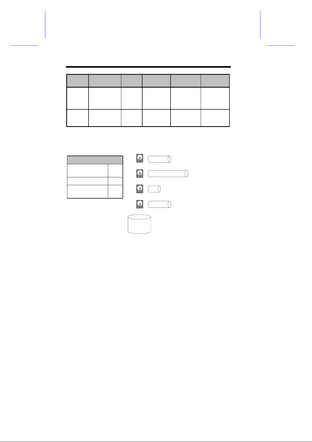
JBOD Single Drive Control
JBOD
Minimum
1
Disks
required
Capacity 1
Redundancy No
2 GB
Logical Drive
3 GB
Logical Drive
1 GB
Logical Drive
= 2 GB Hard Drive
=
=
1 GB Hard Drive
3 GB Hard Drive
2 GB
Logical Drive
=
2 GB Hard Drive
JBOD stands for Just a Bunch of Drives. The controller treats each
drive as a stand-alone disk, therefore each drive is an independent
logical drive. JBOD does not provide data redundancy.
RAID 0 Disk Stripping
Logical Drive
Block 1
Block 2
Block 3
Block 4
Block 5
Block 6
Block 7
Block 8
.
.
Minimum Disks required 2
Capacity N
Redundancy No
Block 1
Block 3
Block 5
Block 7
RAID 0
Physical Disks
Striping
.
.
Block 2
Block 4
Block 6
Block 8
.
.
Chapter 3 Functional Descriptions
9
Page 28

RAID 0 provides the highest performance but no redundancy. Data in
the logical drive is striped (distributed) across several physical drives.
RAID 1 Disk Mirroring
Logical Drive
Block 1
Block 2
Block 3
Block 4
Block 5
Block 6
Block 7
Block 8
.
.
Physical Disks
Block 1
Block 2
Block 3
Block 4
.
.
Mirroring
Mirror 1
Mirror 2
Mirror 3
Mirror 4
.
.
RAID 1
Disks required 2
Capacity N/2
Redundancy Yes
RAID 1 mirrors the data stored in one hard drive to another. RAID 1
can only be performed with two hard drives. If there are more than two
hard drives, RAID (0+1) will be performed automatically.
10
User’s Guide
Page 29

RAID (0+1) Disk Striping with Mirroring
Physical Disks
Logical Drive
Block 1
Block 2
Block 3
Block 4
Block 5
Block 6
Block 7
Block 8
.
.
Block 1
Block 3
Block 5
Block 7
.
.
Mirror 1
Mirror 3
Mirror 5
Mirror 7
.
.
Striping
Mirror
Striping
Block 2
Block 4
Block 6
Block 8
.
.
Mirror 2
Mirror 4
Mirror 6
Mirror 8
.
.
RAID (0+1)
Minimum Disks required 4
Capacity N/2
Redundancy Yes
RAID (0+1) combines RAID 0 and RAID 1 - Mirroring and Striping.
RAID (0+1) allows multiple drive failure because of the full redundancy
of the hard drives. If there are more than two hard drives assigned to
perform RAID 1, RAID (0+1) will be performed automatically.
"RAID (0+1)" will not appear in the list of RAID
levels supported by the controller. If you wish
to perform RAID 1, the controller will determine
whether to perform RAID 1 or RAID (0+1). This
will depend on the drive number that has been
selected for the logical drive.
Chapter 3 Functional Descriptions
11
Page 30

RAID 3 Disk Striping with Dedicated Parity Disk
Logical Drive Physical Disks
Dedicated
Block 1
Block 2
Block 3
Block 4
Block 5
Block 6
Block 7
Block 8
.
.
Block 1
Block 3
Block 5
Block 7
.
.
Striping
Block 2
Block 4
Block 6
Block 8
.
.
Parity
Parity (1,2)
Parity (3,4)
Parity (5,6)
Parity (7,8)
.
.
RAID 3
Minimum Disks required 3
Capacity N-1
Redundancy Yes
RAID 3 performs Block Striping with Dedicated Parity. One drive
member is dedicated to storing the parity data. When a drive member
fails, the controller can recover/regenerate the lost data of the failed
drive from the dedicated parity drive.
12
User’s Guide
Page 31

RAID 5 Striping with Interspersed Parity
Logical Drive Physical Disks
Block 1
Block 2
Block 3
Block 4
Block 5
Block 6
Block 7
Block 8
.
.
Striping + non-dedicated Parity
Block 1
Parity (3,4)
Block 6
Block 7
.
.
Block 2
Block 3
Parity (5,6)
Block 8
.
.
Parity (1,2)
Parity (7,8)
Block 4
Block 5
.
.
RAID 5
Minimum Disks required 3
Capacity N-1
Redundancy Yes
RAID 5 is similar to RAID 3 but the parity data is not stored in one
dedicated hard drive. Parity information is interspersed across the
drive array. In the event of a failure, the controller can
recover/regenerate the lost data of the failed drive from the other
surviving drives.
Chapter 3 Functional Descriptions
13
Page 32

Drive Failure Management
Global and Local Spare Drive
Local Spare Drive
LS
Local Spare Drive is a standby drive
assigned to serve one specified
logical drive. When a member drive
of this specified logical drive fails, the
1 2
3
Logical Drive
Assigns one Local Spare
Drive to a logical drive
Global Spare Drive
does not only serve
one specified logical
drive. When a member
drive from any of the
logical drive fails, the
Global Spare Drive will
join that logical drive
and automatically
starts to rebuild.
Local Spare Drive becomes a
member drive and automatically
starts to rebuild.
Local
Spare
Drive
1 2
X
LS
Logical Drive
When one member
drive fails, the Local
Spare Drive joins the
logical drive and
automatically starts
to rebuild.
3
14
User’s Guide
Page 33

Global Spare Drive
GS
Global Spare Drive
GS
Global Spare Drives serve
any logical drives.
1 2
3
Logical Drive 0
1 2
3
Logical Drive 0
1 2
Logical Drive 1
Global Spare Drive
GS
1 2
X
GS
Logical Drive 1
Global
Spare
Drive
1 2
34
Logical Drive 2
When a member drive from any logical
drive fails, the Global Spare Drive
joins that logical drive and
automatically starts to rebuild.
1 2
34
Logical Drive 2
The AA-3102RS RAID controller provides both Local Spare Drive and
Global Spare Drive functions. On certain occasions, applying these
two functions together will better fit various needs. Take note though
that the Local Spare Drive always has higher priority than the
Global Spare Drive.
Chapter 3 Functional Descriptions
15
Page 34

In the example shown below, the member drives in Logical Drive 0 are
9 GB drives, and the members in Logical Drives 1 and 2 are all 4 GB
drives. It is not possible for the 4 GB Global Spare Drive to join
Logical Drive 0 because of its insufficient capacity. However using a
9GB drive as the Global Spare drive for a failed drive that comes from
Logical Drive 1 or 2 will bring huge amount of excess capacity since
these logical drives require 4 GB only. In the settings below, the 9 GB
Local Spare Drive will aid Logical Drive 0 once a drive in this logical
drive failed. If the failed drive is in Logical Drive 1 or 2, the 4 GB Global
Spare drive will immediately give aid to the failed drive.
Local Spare Drive
LS
(9GB)
1 2
(9GB)(9GB)
3
(9GB)
Logical Drive 0
1 2
(4GB) (4GB)
Logical Drive 1
Global Spare Drive
GS
(4GB)
1 2
(4GB) (4GB)
34
(4GB) (4GB)
Logical Drive 2
Local Spare Drive always
has higher priority than
Global Spare Drive.
Identifying Drives
Assuming there is a failed drive in the RAID 5 logical drive, make it a
point to replace the failed drive with a new drive to keep the logical
drive working.
When trying to remove a failed drive and you mistakenly removed the
wrong drive, you will no longer be able to read/write the logical drive
because the two drives may have already failed.
16
User’s Guide
Page 35

To prevent this from happening, the controller provides an easy way of
identifying for the failed drive. That is, the read/write LED of the failed
hard drive will light. This LED will prevent you from removing the
wrong drive, and is also helpful when locating for a drive.
Flash Selected SCSI Drive
The Read/Write LED of the drive you selected
will light steadily for about one minute.
This applies to firmware
versions 2.11 and above.
Flash All SCSI Drives
The Read/Write LED of all connected drives
will light for about one minute. If the LED of the
defective drive did not light on the "Flash
Selected SCSI Drive" function, use "Flash All
SCSI Drives". The "Flash All SCSI Drives"
function will light LEDs of all the drives except
the defective one.
R/W LED
R/W LED
LED Steadily ON
R/W LED
R/W LED
LED Steadily ON
LED Steadily ON
LED Steadily ON
LED Steadily ON
This applies to firmware
versions 2.11 and above.
Chapter 3 Functional Descriptions
LED Steadily ON
17
Page 36

Automatic Rebuild and Manual Rebuild
Automatic Rebuild
One member drive
fails in logical drive
Any
Local Spare Drive
assigned to this
logical drive?
No
Any
Global Spare Drive
assigned to this
logical drive?
No
Wait for
manual rebuild
Yes
Yes
Rebuild using the
Local Spare Drive
Rebuild using the
Global Spare Drive
When a member drive in the logical drive failed, the controller will first
check whether there is a Local Spare Drive assigned to this logical
drive. If yes, it will automatically start to rebuild.
If there is no Local Spare Drive available, the controller will search for
a Global Spare Drive. If there is a Global Spare Drive, it will
automatically rebuild the logical drive.
If neither Local Spare Drive nor Global Spare Drive is available, the
controller will not try to rebuild unless the user applies a forced-manual
rebuild.
18
User’s Guide
Page 37

Manual Rebuild
rebuild
been replaced?
When a user applies forced-manual rebuild, the controller will first
check whether there is any Local Spare Drive assigned to this logical
drive. If yes, it will automatically start to rebuild.
If there is no Local Spare Drive available, the controller will search for
a Global Spare Drive. If there is a Global Spare Drive, it will
automatically rebuild the logical drive.
User applies
forced-manual
Any
Local Spare Drive
assigned to this
logical drive?
No
Any
Global Spare Drive
assigned to this
logical drive?
No
Has the failed drive
No
Wait for
manual rebuild
Yes
Yes
Yes
Rebuild using the
Local Spare Drive
Rebuild using the
Global Spare Drive
Rebuild using the
replaced drive
Chapter 3 Functional Descriptions
19
Page 38

If neither Local Spare Drive nor Global Spare Drive is available, the
controller will detect the SCSI channel and ID of the failed drive. Once
the failed drive has been replaced by a new drive/used drive, it starts
to rebuild using the replaced drive. If there is no available drive for
rebuilding, the controller will not try to rebuild again until the user
applies another forced-manual rebuild.
Concurrent Rebuild in RAID (0+1)
RAID (0+1) allows multiple drive failure and concurrent multiple drive
rebuild. Newly replaced drives must be scanned and set as Local
Spare Drives. These drives will be rebuilt at the same time (you do not
need to repeat the rebuilding process for each drive).
20
User’s Guide
Page 39

Disk Array Parameters
Rebuild Priority
Rebuilding time will depend on the capacity of the logical drive. The
AA-3102RS RAID controller provides background rebuilding ability.
Meaning, the controller is able to serve other I/O requests while
rebuilding the logical drives. The rebuilding process is totally
transparent to the host computer or the operating system.
The background rebuild process has four priority options:
• Low
• Normal
• Improved
• High
The default priority is "Low" which uses the controller’s minimum
resources to rebuild. Choosing "Normal" or "Improved" will speedup
the rebuilding process and choosing "High" will use the controller’s
maximum resources to complete the rebuilding process at the shortest
time.
Rebuild priority can be configured through the RS-232C Terminal
Interface, Acer RAID Manager or the front panel.
Verify-after-Write
The controller has the ability to force the hard drives to verify after data
has been written to the media of the HDD. There are three selectable
methods:
• Verification on LD Initialization Writes
Performs Verify-after-Write while initializing the logical drive.
Chapter 3 Functional Descriptions
21
Page 40

• Verification on LD Rebuild Writes
Performs Verify-after-Write during the rebuilding process.
• Verification on LD Normal Drive Writes
Performs Verify-after-Write during normal I/O requests.
Each method can be enabled or disabled individually. Hard drives will
perform Verify-after-Write according to the selected method.
The "Verification on LD Normal Drive Writes" method
will affect "write" performance during normal use.
22
User’s Guide
Page 41

Cache Parameters
Optimization for Sequential or Random I/O
When using RAID with applications such as video or image oriented
applications, the application reads/writes from the drive using largeblock, sequential files instead of small-block, random access files.
The AA-3102RS RAID controller provides the options to optimize for
large-sequential I/O or optimize for small-random I/O access.
"Optimization for Sequential I/O" provides larger stripe size (block size,
also known as Chunk size) than "Optimization for Random I/O". A lot
of the controller’s internal parameters will also be changed to optimize
for sequential or random I/O. The change will take effect after the
controller reboots.
If the existing logical drives were built with "Optimization for Random
I/O", these logical drives will not read/write when using "Optimization
for Sequential I/O" (shows "INVALID") and vice versa because the
stripe size is different. Change it back to the original setting and reset
the controller to make available the logical drive data again.
Changing the setting to "Optimization for Sequential
I/O" or "Optimization for Random I/O" should be
performed only when no logical drive exist.
Otherwise, you will not be able to access the data in
the logical drive later on.
Chapter 3 Functional Descriptions
23
Page 42

Drive-Side SCSI Parameters
SCSI Motor Spin-up
When the power supply is unable to provide sufficient current for all
the hard drives and controllers that are powered-up at the same time,
spinning-up the hard drives serially is one of the best way of
consuming lower power-up current.
By default, all hard drives will spin-up when powered-on. These hard
drives can be configured so that all of them will not spin-up at poweron. There are 3 methods of spinning-up the hard drive’s motor: Spinup at power-on, Spin-up serially in random sequence or Spin-up by
SCSI command. Please refer to the hard drive’s user’s manual for
instructions on configuring the hard drive using the "Spin-up by SCSI
command". The procedure for each brand/model of hard drive should
vary.
Configure all the hard drives as above and enable "SCSI Motor SpinUp" in Drive-Side SCSI Parameters. Power off all hard drives and
controller, and power them on again. All the hard drives will not spinup at this time. The controller will then spin-up the hard drives one by
one at four seconds interval.
If the drives are configured as "Delay Motor Spin-up"
or "Motor Spin-up in Random Sequence," some of
these drives may not be ready yet for the controller to
access when the system powers up. Increase the
disk access delay time so that the controller will wait
a longer time for the drive to be ready.
SCSI Reset at Power Up
By default, when the controller is powered up, it will send a SCSI bus
reset command to the SCSI bus. When disabled, it will not send a
SCSI bus reset command on the next power-up.
24
User’s Guide
Page 43

When connecting dual host computers to the same SCSI bus, the
SCSI bus reset will interrupt all the read/write requests that are being
performed. This may cause some operating systems or host
computers to act abnormally. Disable the "SCSI Reset at Power-up" to
avoid this situation.
Disk Access Delay Time
Sets the delay time before the controller tries to access the hard drives
after power-on. The default is 15 seconds.
Chapter 3 Functional Descriptions
25
Page 44

SAF-TE Enclosure Management
What is SAF-TE?
SAF-TE stands for SCSI Accessed Fault-Tolerant Enclosures. It is an
enclosure management technology. A SAF-TE-compliant enclosure
monitors the fan temperature, power supply, UPS and also provides
drive status LED’s. The SAF-TE enclosure connects to the RAID
Controller via a SCSI connector. The RAID controller communicates
with the SAF-TE enclosure with standard SCSI commands.
SAF-TE Support
RAID
Front Panel
error alert
GUI RAID Manager
Acer RAID Manager
error alert
error alert
Controller
SCSI
Drive Status
Indicators
SAF-TE
Chipset
Temperature Alert
Signal Input
UPS Failure
Signal Input
Cooling Fan
Failure
Signal Input
Power Supply
Failure
Signal Input
• SAF-TE chipset connects to the drive channel of the
controller together with the other SCSI drives.
How Does SAF-TE work?
The SAF-TE device (often a back plane within a drive-bay enclosure)
must occupy a connector on one of the drive channels’ SCSI cables.
The presence of a SAF-TE device will be detected and its presence
will be displayed in both the RS-232 terminal emulation and the Acer
RAID Manager programs.
26
User’s Guide
Page 45

Dynamic Logical Drive Expansion
What Is It and How Does It Work?
Before Dynamic Logical Drive Expansion, increasing the capacity of a
RAID system using traditional methods meant backing up, re-creating
and then restoring. Dynamic Logical Drive Expansion (a new feature
of firmware version 2.11) allows users to add new SCSI hard disk
drives and expand a RAID 0, 3 or 5 Logical Drive without powering
down the system.
Two Modes of Dynamic Logical Drive Expansion
There are two modes of Dynamic Logical Drive Expansion: Mode 1
and Mode 2.
Dynamic Logical Drive Expansion
Mode 1
Chapter 3 Functional Descriptions
Mode 2
27
Page 46

Mode 1 Expansion involves adding more SCSI hard disk drives to a
logical drive, which may require that the user obtain an enclosure with
more drive bays. The data will be re-striped onto the original and newly
added disks.
RAID Expansion - Mode 1
2GB
RAID 5 Logical Drive - 4GB
RAID
Expansion
In the figure above, new drives are added to increase the capacity of a
4-Gigabyte RAID 5 logical drive. The two new drives increase the
capacity to 8 Gigabytes.
Mode 2 Expansion, on the other hand, requires the same number of
higher-capacity SCSI hard disk drives for a given logical drive.
2GB
2GB
2GB
2GB
+
Add-in New Drives
2GB
RAID 5 Logical Drive - 8GB
2GB
+
2GB
2GB
2GB
28
User’s Guide
Page 47

RAID Expansion - Mode 2 (1/3)
2 GB
2 GB 2 GB
RAID 5 (4GB)
1
Copy and Replace each of the member drives. Even
if one member drives fails during the Copy and
Replace, the logical drive will still be available for
access.
The original logical drive
2 GB
2 GB 2 GB
RAID 5 (4GB)
4 GB
New
Drive
Copy and Replace
one of the member drives
In use
Unused
The figure above illustrates expansion of the same 4-Gigabyte RAID 5
logical drive using Mode 2 Expansion. Drives are copied and replaced,
one by one, onto three higher-capacity drives.
RAID Expansion - Mode 2 (2/3)
2
Copy and Replace each member drive. After all the
member drives have been replaced, execute the
“RAID Expansion” to use the additional capacity.
2 GB
2 GB 4 GB
RAID 5 (4GB)
Copy and Replace the other member drives one by one
until all the member drives have been replaced
Chapter 3 Functional Descriptions
4 GB
New
Drive
In use
Unused
29
Page 48

This results in a new 4-Gigabyte, RAID 5 logical drive composed of
three physical drives. The 4 Gigabytes of increased capacity is in a
new partition.
• The increased capacity from Mode 1 Expansion
of a logical drive will be a new partition.
• At the time of this printing, Firmware version 2.11
does not support the "Copy and Replace"
function that is required for Mode 2 Expansion.
Third-party hard disk utilities may be used for
Mode 2 Expansion of logical drives. Later
versions of the firmware will support "Copy and
Replace."
Example: RAID Expansion in Windows NT Server
Limitations When Using Windows NT 4.0
1. Only the Windows NT Server Disk Administrator includes the
Extend Volume Set function; Windows NT Workstation does not
have this feature.
2. The system drive (boot drive) of a Windows NT system cannot be
extended.
3. The drive that will be extended should be using the NTFS file
system.
The Example:
The following example demonstrates the expansion of a 900MB RAID
0 logical drive. The Hyper Terminal emulation software that comes
with Windows 95/NT is used to connect to the RAID controller via RS-
232.
30
User’s Guide
Page 49

You can view information about this drive in the Windows NT Server’s
Disk Administrator.
Chapter 3 Functional Descriptions
31
Page 50

Place the cursor on Disk 1, right-click your mouse, and select
"Properties." You will see that the total capacity for the Drive E: is just
under 900MB.
32
User’s Guide
Page 51

Follow the steps described in section 7.2.8 to add SCSI disk drives
and perform Mode 1 Dynamic Logical Drive Expansion.
The 900MB logical drive has become a 1800MB logical drive. Place
the cursor on that logical drive, and then press <Enter>.
Chapter 3 Functional Descriptions
33
Page 52

From the menu, select Partition Logical Drive. You will see that the
1800MB logical drive is composed of two 900MB partitions.
Follow the directions in Chapter 7 section “Mapping a Logical Drive to
a Host LUN” to map the new partition to a Host LUN. The new partition
must be mapped to a host LUN in order for the HBA (host-bus
adapter) to see it. Once you have mapped the partition, reboot
Windows NT. The HBA should be able to detect an additional "disk."
34
User’s Guide
Page 53

Return to Windows NT Server’s Disk Administrator. There now exists
a Disk 2 with 900MB of free space. Click on Disk 2 to select it.
From the "Partition" menu, select "Extend Volume Set."
Chapter 3 Functional Descriptions
35
Page 54

The screen will display that volume set of Drive E: has been extended
by the 900MB in Disk2. Move the cursor to "Commit Changes Now" to
confirm that you want the free space to become a part of the same
logical drive.
Logical Drive E: is now composed of two 900MB partitions with a total
volume of 1800MB. To see this, hold down on the <Ctrl> key and
select both Disk 1 and Disk2; then right-click your mouse and select
"Properties."
36
User’s Guide
Page 55

Drive E: now has a capacity just under 1800MB.
Chapter 3 Functional Descriptions
37
Page 56

Page 57

Chapter 4 Hardware Installation
AA3102RS
Locations of the Parts
POWER
IFT-3102 V2.11
Ready
BUSY
ATTEN
ENT
ESC
Front View
POWER Lighted LED indicates power is on.
BUSY Unlit indicates no activity.
Blinking indicates data is being accessed.
Lighted LED indicates unprocessed cached data is
still in the memory.
ATTEN Lights when an error message appears or service
is required, e.g., when a drive fails and needs to be
replaced.
t s buttons Scroll through available options.
ENT button Choose or executes an option.
ESC button Returns to previous menu or cancel selection.
2 x 16 LCD AA-3102RS controller
Chapter 4 Hardware Installation 39
Page 58

Rear View of the Main Board
JP6: SCSI Channel-1
JP1: SCSI Channel-0
JP2: Redundant Controller Port
P2: Power Socket
P1: RS-232 Port COM1
JP7: SCSI Channel-2
COM2
40
User’s Guide
Page 59

Top View of the Main Board
CPU
JP7: SCSI Channel-2
JP1:
P2: Power Socket
JP2:
P1:
JP5: Fault Bus
JP4: Fault Bus
7-Segment LED
JP18
JP16
500127
500126
JP6: SCSI Channel-1
SCSI Channel-0
1
RS-232 Port
Infortrend
Infortrend
Redundant Controller Port
SIMM-1
SIMM-2
Chapter 4 Hardware Installation 41
Page 60

Top View of the Daughter Board (AA-9073UWS)
JP1: SCSI Channel-3 JP2: SCSI Channel-4
JP5: SCSI Channel-5
SCSI Chip SCSI ChipSCSI Chip
Top View of the Daughter Board (AA-9072UWD)
JP6: SCSI Channel-3 JP7: SCSI Channel-4
SCSI Chip SCSI Chip
Pin 1 of the terminator resistors
42
User’s Guide
Page 61

Top View of the Daughter Board (AA-9073U2)
JP5: Ultra2 SCSI Channel-5
JP1: Ultra2 SCSI Channel-3
JP2: Ultra2 SCSI Channel-4
SCSI Chip
SCSI Chip
SCSI Chip
Chapter 4 Hardware Installation 43
Page 62

Installing DRAM SIMM
The AA-3102RS controller requires a minimum of 4
Mbytes DRAM SIMM (with or without parity function)
installed in a SIMM socket in order for it to operate. The
controller is normally delivered without any DRAM
installed.
The following are guidelines on using DRAMs:
• Use 72-pin 60 ns DRAM or 60 ns EDO RAM SIMM module. EDO
RAM is recommended for better performance.
• A SIMM, with or without parity, can be auto-detected by the
controller. A SIMM with parity is recommended for security.
• The minimum DRAM required is 4 Mbytes in-stalled in a SIMM
socket, however 8 Mbytes is recommended.
• The controller supports 4 MB, 8 MB, 16 MB, 32 MB, 64 MB
DRAM SIMM module. Maximum DRAM size is 128 Mbytes.
To install the DRAM SIMM:
1. Power off the system and disconnect the power connector.
2. Insert the DRAM SIMM vertically into the socket making sure the
key is on the left side (1). Now push the module backward until
the hooks on both sides of the socket snap into place (2).
44
User’s Guide
Page 63

Installing the SCSI Channel Upgrade Daughter
Board
The AA-3102RS’s base module has 3 Ultra-Wide SCSI channels.
Installing a SCSI channel upgrade daughter board (AA-9073UWS, AA9072UWD, or AA-9073U2) onto the base module allows you to
expand up to a total of 6 SCSI channels. (Only one daughter board
can be mounted at a time).
• AA-9073UWS: 3 Single-Ended Ultra Wide SCSI Channels
• AA-9072UWD: 2 Differential Ultra Wide SCSI Channels
• AA-9073U2: 3 Ultra2 Wide SCSI Channels
To install the SCSI channel upgrade daughter board:
1. Make sure the power of the host system and drives are off.
2. Position the daughter board so that the SCSI connectors are
facing the rear of the controller.
3. While at it, make sure the connector pins on the daughter board
are aligned with the two header connectors on the controller’s
main board.
4. Press both sides of the daughter board downward so that the
connector pins on the daughter board insert into the header
connectors on the main board. Make sure the daughter board is
seated properly.
Chapter 4 Hardware Installation 45
Page 64

Insert
Daughter Board
Insert
RAID Controller Main Board
46
User’s Guide
Page 65

Battery Backup
The AA-3102RS controller operates using cache memory. However,
when power failure occurs, the cache memory may contain buffered
data that has not yet been written to the hard disks. These buffered
data are not retrievable when power returns.
To avoid this from happening, a battery backup solution (AA-9070 and
AA-9010) is available to provide up to 100 hours of back-up time. The
AA-9070 is a battery backup daughter board that plugs into the
controller. The AA-9010 is a battery pack that connects to the AA9070 battery backup daughter board. Several AA-9010’s can be daisy
chained to provide long hours of unattended operation over a period of
days.
To install the battery backup daughter board and battery pack:
1. Make sure the power of the controller and drives are off.
1 2
19 20
2. Locate for the female pin socket (JP16) on the AA-3102RS
mainboard. Remove the socket plug that is on JP16.
1 2
19 20
PULL
Chapter 4 Hardware Installation 47
Page 66

3. Now install the AA-9070 battery backup daughterboard onto the
mainboard.
Insert
Battery Backup
Daughter Board
Insert
Insert
RAID Controller Main Board
4. Connect the AA-9010 battery pack to JP10 located on the AA9070 daughter board.
Connect to JP10
Inductor
Inductor
Battery Backup Daughter Board
48
Battery Pack
JP10
Cap.
User’s Guide
Page 67

It is a must to install the socket plug back to JP16 once
you have removed the AA-9070 battery backup
daughterboard. The controller will not work if you fail to
do so.
Chapter 4 Hardware Installation 49
Page 68

Power Connection
The power input and connection of the AA-3102RS controller is exactly
the same as those for hard disk drives. The power connection is
shown below.
1 2
19 20
50
User’s Guide
Page 69

Serial Port Connection and Set-Up
The AA-3102RS controller can be configured via a PC running a VT100 terminal emulation program, or a VT-100 compatible terminal.
The provided interface cable converts the RS-232 signal of the 10-pin
header connector on the controller into a 9-pin D-Sub male connector.
The pin layout of the 9-pin D-Sub male connector is similar to that of a
PC’s serial port and is set as a DTE device. The proper connection of
the cable and pin layout is shown below.
1 2 3 4 5
6 7 8 9
The following are guidelines on using the serial port:
• The serial port’s default is set at 9,600 baud, 8 bit, 1 stop bit and
no parity. Use the COM1 serial port of the controller.
• In most cases, connecting RD, TD and SG are enough to
establish communication with a terminal.
• If you are using a PC as a terminal, any of the VT-100 terminal
emulation software will suffice. Microsoft Windows includes a
terminal emulation program as presented with the "Terminal" icon
in the Accessories window.
Chapter 4 Hardware Installation 51
Page 70

The baud rate can be changed using the front panel. To change the
baud rate:
1. Press ENT for two seconds to enter the Main Menu. Press t or s
to select "View and Edit Configuration ..", then press ENT.
View and Edit
Configuration ..
2. Select "Communication Parameters ..", then press ENT.
Communication
Parameters ..
3. Select "RS-232 Configuration ..", then press ENT.
RS-232
Configuration ..
4. Select "COM1 Configuration ..", then press ENT.
COM1
Configuration ..
5. Select "Baud-rate 9600 ..", then press ENT.
Baud-rate 9600
..
Press t or s to select the baud rate, then press ENT for 2 seconds to
confirm the selected baud rate.
The available baud rates are: 2400, 4800, 9600, 19200
and 38400.
52
User’s Guide
Page 71

Basic Operational setup
An example of the operational setup is shown below:
RAID
Controller
Host CH0
Drive CH1
Drive CH2
(Terminator Enabled)
SCSI cable
SCSI cable
Host Computer
(Terminator Enabled)
Terminator
…..
SCSI cable
Terminator
…..
• The SCSI cable must be shorter than 3 meters.
• Channel 0 is connected to the Host system.
• Drives are connected to drive channels 1 and/or 2.
• SCSI nodes on the same channel have their own unique ID
number.
• Both the Host and drive SCSI cables are properly terminated.
• The terminator of all the hard drives must be disabled.
• The power supply is attached.
• All operation parameters are properly set.
To connect the components:
1. Make sure power is off or the power connector is disconnected.
Chapter 4 Hardware Installation 53
Page 72

2. Connect channel 0 of the controller to the Host system's SCS-I
port using a suitable SCSI cable.
Channel 0 is the default Host interface using ID
number ‘0’. Any of the channels can also be set as
the Host interface. More than one channel can be set
as the Host interface when operating with redundant
Host or multiple Host systems.
3. Make sure the host side of the SCSI cable is properly terminated.
4. Assign a unique SCSI ID for every hard disks that are to be
connected on the same SCSI cable; between ID numbers ‘0’ and
‘6’ and ‘8’ and ‘15’. The default ID of the controller’s channel 0 is
‘7’.
5. Connect the other end of the drive SCSI cable to one of the
remaining channel on the controller.
6. Connect the connectors located at the middle of the drive SCSI
cable to the hard disk(s).
7. Terminate the SCSI cable by installing an external terminator on
the last connector. Terminators on all the hard drives must be
removed so that removing a hard drive will not affect cable
termination.
54
User’s Guide
Page 73

In-band SCSI
What is it and why do you need it?
These days more and more external devices require communication
with the host computer for device monitoring and administration. This
is usually done through RS-232C ports.
Acer now offers an alternative means of communication for its RAID
controllers—In-band SCSI. The traditional way for SCSI controllers to
communicate with the host computer has been via software (such as
the Acer RAID Manager ) using an RS-232C connection. With In-band
SCSI, integrators have more flexibility. They may use RS-232C or the
existing SCSI cable instead.
How does it use the SCSI cable? In-band SCSI technology translates
the original commands into standard SCSI commands. These SCSI
commands are then sent to and received from the SCSI raid
controller. The Acer RAID Manager can administrate the RAID
controller just as it could before via RS-232C. (Note: It is assumed
that users of In-band SCSI possess the following: a third-party SCSI
adapter and a channel on their Acer RAID controller that can be
designated as a host channel.) Both of these are required for In-band
SCSI communication between the host and the RAID controller. )
Chapter 4 Hardware Installation 55
Page 74

How Do You Configure the Acer RAID Manager to Use
Config Parms
In-band SCSI?
RAID Controller Adjustments
Don't disconnect your RS-232C cable yet! It is required for another 10
minutes or so. Some adjustments must be made to the RAID
controller and to the host computer's SNMP settings before the two
can communicate using SCSI commands. (Note: The SNMP settings
must be changed prior to installation of the Acer RAID Manager . See
SNMP Settings below for a detailed explanation.) The RAID controller
settings can be changed using the Front Panel. (Your front panel may
be different in appearance from the one shown in this example.)
Controller v2.11
Ready
BUSY POWER
ATTEN
From the Main Menu, press t or s to select "View and Edit
Configuration Parameters. "
ESCENT
View and Edit
Press <Enter>; and then use the t or s to select "Host-side SCSI
Parameters." Then press <Enter>.
Host-side SCSI
Parameters ..
56
User’s Guide
Page 75

You will need to make adjustments in the following four submenus:
Peripheral Device Type, Peripheral Device Qualifier, Device Support
for Removable Media, and LUN Application. Different host operating
systems require different adjustments. Look at the table below to find
the proper settings for your host operating system.
Peripheral Device Type Parameters Reference for Various
Operating Systems
Operating
System
NT 4.0 3 connected disabled All Undefined
NT 5.0 3 connected enabled All Undefined
NetWare
4.x
SCO Unix
5.0x
UnixWare
2.1x
Solaris
2.5.x/2.6
Peripheral
Device Type
1f connected disabled All Undefined
7f connected either is okay All Undefined
3 connected either is okay All Undefined
7f connected either is okay All Undefined
Peripheral
Device
Qualifier
Device Support
for Removable
Media
LUN
Applicability
LUNs
LUNs
LUNs
LUNs
LUNs
LUNs
Peripheral Device Type Settings
Device Type Setting
No Device Present 7f
Direct-access Device 0
Sequential-access Device 1
CD-ROM Device 5
Scanner Device 6
MO Device 7
Unknown Device 1f
Processor Type 3
Chapter 4 Hardware Installation 57
Page 76

Example: Settings for Windows NT 4.0
Connected
The settings for Windows NT 4.0 are provided here as an example.
For the settings for other operating systems, please refer to the table
above, Peripheral Device Type Parameters Reference for Various
Operating Systems.
On the front panel, use t or s to select "Peripheral Device Type
Parameters"; and then press <Enter>.
Periph Dev
Type Parameters
(For this example, we assume that there are currently no peripheral
devices.)
Device Type No Device (0x7f)
Press t or s to choose "Unknown Device - 3".
Set Device Type?
Unknown (0x3)
Press <Enter> to confirm the selection. Now that we have changed the
Peripheral Device Type, let us set the Peripheral Device Qualifier.
Press <Esc> to return to the sub-menu’s mentioned above. Use the
arrow keys to scroll down to Device Qualifier., press t or s to select
"Device Qualifier Connected. "
The default setting is "Connected." If your Front Panel reads
"Disconnected," press <ENT> and you will be prompted to change to
"Connected". If your Device Qualifier setting reads "Connected," press
<Esc> to return to the Host-side SCSI submenu.
Device Qualifier
58
User’s Guide
Page 77

Use the t or s to select Support for Removable Media. The default
Media - Disabled
Undefine LUN-0’s
Undefine LUN-0’s
setting is "Disabled." If the LCD reads "Enabled," press <Enter> and
you will be prompted to accept a change. If the screen reads
"Disabled," press <Esc> to return to the Host-side SCSI submenu’s.
SupportRemovable
Press t or s to select "LUN Application"; and then press <Enter>.
The default setting is "All Undefined LUN."
LUN ApplicationAll Undefine LUN
Press <Enter> and use t or s to select "Undefined LUN-0’s."
Applies to ?
Press <Enter> to accept. The screen should display the following
message.
LUN Application-
The RAID controller adjustments necessary to use In-band SCSI have
been completed. For locally accessing the host computer (see section
Local Connection — SNMP Not Required), all steps have been
completed. For remotely accessing the host computer, further
adjustments must be made (see section Remote Connection —
SNMP Required).
Chapter 4 Hardware Installation 59
Page 78

Using In-band SCSI in Acer RAID Manager
Local Connection — SNMP Not Required
If you are using the Acer RAID Manager on the host computer that is
using In-band SCSI -- i.e., ‘local access’ -- SNMP service is not
required. You may now connect by going to FILE>CONNECT and
selecting the port address.
Remote Connection — SNMP Required
SNMP Service is required to administrate a RAID controller installed in
a remote computer. This passage describes how to establish a
connection from the Acer RAID Manager to a RAID controller that is
connected to a remote host via In-band SCSI. For information
regarding other operations and of the Acer RAID Manager , please
refer to the Acer RAID Manager User Guide.
60
User’s Guide
Page 79

LAN
Win NT
RAID
Controller
Host Computer
Manager Site
Agent Site
Acer
+
GUI
RAID
Manager
With In-band
SCSI SNMP
Agent Installed
In the figure above, the "Agent Site" is a host computer connected to a
RAID controller via a SCSI cable. The "Manager Site" is a Windows
NT system with the Acer RAID Manager . The Agent Site could be
running an operating system other than Windows NT. Acer provides
the In-band SCSI SNMP agents for the following operating systems:
• Windows NT
• NetWare
The Manager Site should be a Windows NT Workstation or Server
with SNMP service and the Acer RAID Manager installed.
BASIC PROCEDURES TO ESTABLISH THE CONNECTION
The following criteria must be met for the Agent Site and Manager
Site:
Chapter 4 Hardware Installation 61
Page 80

Checklist for Agent Site
1. The host computer is connected to the RAID controller via the host
SCSI cable (the cable which is used to transfer data between the
host computer and the RAID — there’s no need for an extra SCSI
cable.)
2. The host computer’s operating system has SNMP service
installed.
3. The host computer has the In-band SCSI SNMP agent installed
for the corresponding operating system. (The example described
herein is Windows NT.)
4. The host computer is up and running.
This following applies to Windows NT 4.0 with Service
Pack 3: if the "SNMP Service" is installed after the
Service Pack 3 has been installed, Service Pack 3 must
be re-installed in order for the SNMP service to work
properly.
Checklist for Manager Site
1. The system is running Windows NT (Workstation or Server) and
has SNMP Service installed.
2. The Infortrend Acer RAID Manager was installed with the "SNMP
Manager Site" option selected.
3. The Acer RAID Manager is running.
This following applies to Windows NT 4.0 with
Service Pack 3: if the "SNMP Service" is installed
after the Service Pack 3 has been installed, Service
Pack 3 must be re-installed in order for the SNMP
service to work properly.
62
User’s Guide
Page 81

Example Settings for Agent Site Using Windows NT
1. Install SNMP Service in Windows NT. Look for the "Network"
icon in the Control Panel. Double click on the "Network" icon to
open it.
The Properties window appears. Choose the "Service" tab. If the
SNMP Service is already installed, please go ahead to step called
"Install the SNMP Agent and Acer RAID Manager ." If the SNMP
Service is not yet installed, click on "Add" and choose "SNMP Service"
to install.
Chapter 4 Hardware Installation 63
Page 82

This following applies to Windows NT 4.0 with
Service Pack 3: if the "SNMP Service" is installed
after the Service Pack 3 has been installed, Service
Pack 3 must be re-installed in order for the SNMP
service to work properly.
2. Install the SNMP Agents and Acer RAID Manager . The Acer
RAID Manager can install the In-band SCSI SNMP Agent during
installation. During Acer RAID Manager installation, be sure to
select both the "SNMP Manager Site" and "SNMP Agent Site"
options. Complete the installation by following the on-screen
instructions.
Example Settings for Manager Site
1. Install the SNMP manager and Acer RAID Manager . During the
installation of Acer RAID Manager , click to select the option
"SNMP Manager Site." Complete the installation by following the
on-screen instructions.
64
User’s Guide
Page 83

2. Run the Acer RAID Manager . Start the connection by choosing
FILE>CONNECT>SNMP.
3. The "Setting of SNMP Interface" window appears. Enter the IP
address and community name of the Agent Site. For "Agent-site
Communication Type," choose "SCSI Bus Interface." The "Controller
Index" refers to the sequence of the RAID controller which is going to
be administrated. If only one RAID controller is installed in the agent
site computer, choose "0". If there is more than one RAID controller
installed in the agent site computer, choose "1" to administrate the
second RAID controller. Choose "2" to administrate the third RAID
controller, etc.
Chapter 4 Hardware Installation 65
Page 84

4. After the connection is established, all of the operations in the
Acer RAID Manager are the same as before (please refer to the
Acer RAID Manager User Guide for complete details on its
operation.)
66
User’s Guide
Page 85

Chapter 5 Quick Setup
A "Logical Drive" is a set of drives grouped together
to operate under a given RAID level and appears as
a single contiguous drive. The AA-3102RS controller
is capable of grouping connected drives to as many
as 8 logical drives, each configured on the same or
different RAID levels. A logical drive can be further
divided into a maximum of 8 "Partitions". During
operation, the host sees an unpartitioned logical drive
or a partition of a partitioned logical drive as one
single physical drive.
Front Panel
The AA-3102RS controller’s default configurations are based on the
number and location of the drives installed. If this is your first time to
install, we suggest that you try the default configurations provided by
the "Quick Installation" function. This will allow you to immediately
verify whether the system is working. Further optimization can then be
made later on.
Quick Setup assumes there is only one host channel.
Press ENT for 2 seconds to enter the Main menu. Select "Quick
Logical Drive Install ..", then press ENT.
Quick Logical
Drive Install ..
Chapter 5 Quick Setup 67
Page 86

The number of drives and the first possible RAID level will appear on
the LCD display. Use t or s to select the RAID level, then press ENT
for two seconds to enter the selected RAID level. The controller will
now start initialization.
Set TDRV=4 with
LG RAID5+Spare ?
The RAID levels available are as follows:
1 Drive = NRAID (Disk Spanning)
2 Drives = RAID0 or RAID1
3 Drives = RAID0
RAID1 + Spare
RAID3
RAID5
>3 Drives = RAID0
(Odd) RAID1 (0+1)+ Spare
RAID3
RAID3 + Spare
RAID5
RAID5 + Spare
>3 Drives = RAID0
(Even) RAID1 ( 0 + 1)
RAID3
RAID3 + Spare
RAID5
RAID5 + Spare
Init Parity 10%
Please Wait!
The LCD will display the logic-al drive’s information after completing
initialization.
LG=0 RAID5 DRV=3
4123MB GD SB=1
68
User’s Guide
Page 87

RS-232 Terminal Interface
The keys used when operating via the terminal are as follows:
←← →→ ↑↑ ↓↓ To select options.
[Enter] To go to a submenu or to execute a selected option.
[Esc] To escape and go back to the previous menu.
[Ctrl] [L] The controller will refresh the screen information.
If the RS-232 cable is connected while the controller
is powered on, press [Ctrl] [L] to refresh the screen
information.
The initial screen appears when the controller is powered-on. Use ↑↑ ↓↓
arrow keys to select the desired terminal emulation mode, then press
[ENTER] to enter the Main Menu.
Type Q or use the ↑↑ ↓↓ keys to select "Quick installation", then press
[Enter]. Choose Yes to create a logical drive.
Chapter 5 Quick Setup 69
Page 88

All possible RAID levels will be displayed. Use the - ¯ keys to select a
RAID level, then press [Enter]. The assigned spare drive will be a
Local Spare Drive, not a Global Spare Drive.
The controller will start initialization and automatically map the logical
drive to LUN 0 of the first host channel.
70
User’s Guide
Page 89

Chapter 6 Configuring RAID
Starting to Build a RAID System Drive
Create
Logical Drive
The following figure is a basic flowchart when configuring a RAID
system. Hardware installation must be completed before any
configurations take place.
When power is turned on, the AA-3102RS RAID controller scans all
the hard drives that are on all the drive channels. If a hard drive was
connected after the controller completes initialization, use the "SCAN
SCSI DRIVE" function to let the controller recognize the newly added
hard drive and configure it as a member of a logical drive or a spare
drive.
In accordance to your requirement, configure a logical drive to contain
one or more hard drives based on the desired RAID level, and partition
the logical drive into one or several partitions. Map each partition as
one system drive (LUN). The host SCSI adapter will recognize the
system drives after re-scanning the host SCSI bus.
Since the controller is totally operating system independent, the
operating system of the host computer will not be able to find out
whether the attached devices are physical hard drives or virtual
system drives created by the RAID controller.
Partition
Logical Drive
Map
Host LUN
(System Drive)
Chapter 6 Configuring RAID 71
Page 90

A “Logical Drive” is a set of drives grouped together
to operate under a given RAID level and appears as
a single contiguous drive. The AA-3102RS controller
is capable of grouping connected drives to as many
as 8 logical drives, each configured on the same or
different RAID levels. A logical drive can be further
divided into a maximum of 8 “Partitions”. During
operation, the host sees an unpartitioned logical drive
or a partition of a partitioned logical drive as one
single physical drive.
72
User’s Guide
Page 91

How the RAID Controller Works?
SCSI Channel, SCSI ID and LUN
A SCSI channel (SCSI bus) can connect up to 15 devices (the SCSI
controller itself excluded) when the Wide function is enabled (16-bit
SCSI). It can connect up to 7 devices (the SCSI controller itself
excluded) when the Wide function is disabled (8-bit SCSI). Each
device has one unique SCSI ID. Two devices owning the same SCSI
ID is not allowed.
The figure on the left is a very good example. If you are to file
document into a cabinet, you must put the document into one of the
drawer. From a SCSI’s point of view, a SCSI ID is like a cabinet, and
the drawers are the LUNs. Each SCSI ID can have up to 8 LUNs
(Logical Unit). Data can be stored into one of the LUNs of the SCSI ID.
Most SCSI host adapters treat a LUN like another SCSI device.
LUN 0
LUN 1
LUN 2
In firmware versions 2.11 or later, each SCSI ID can
support up to 32 LUNs.
Chapter 6 Configuring RAID 73
Page 92

Understanding Step by Step
RAID
Controller
Host CH0
Drive CH1
Drive CH2
(Terminator Enabled)
SCSI cable
SCSI cable
Host Computer
(Terminator Enabled)
Terminator
…..
SCSI cable
Terminator
…..
Physical connection should look similar to the figure shown on the
previous page. The channel connected to the host adapter is the host
channel, and the channels connected to the drives are the drive
channels.
A Logical Drive consists of a group of SCSI drives. Drives in one
logical drive do not have to come from the same SCSI channel. Also,
each logical drive can be configured a different RAID level.
74
User’s Guide
Page 93

Drive Channel 1
ID 5
GB
4
GB
4
ID 0
GB
4
2
GB
ID 3 ID 2
2
GB
GB
2
2
GB
GB
Drive Channel 2
4
ID 6 ID 1 ID 0 ID 14
Local Spare
Drive of LD1Global
RAID 5
8GB
Spare
Drive
RAID 0
6GB
Logical Drive 1Logical Drive 0
A drive can be assigned as the Local Spare Drive of one specified
logical drive, or as Global Spare Drive.
Partition 0 - 2GB
RAID 5
8GB
Logical Drive 0
RAID 0
6GB
Logical Drive 1
Partition 1 - 1GB
Partition 2 - 5GB
Partition 0
2.5GB
Partition 1
1.5GB
You may divide a logical drive into several partitions, or use the entire
logical drive as one single partition.
Chapter 6 Configuring RAID 75
Page 94

Host SCSI Channel
1GB
Logical Drive 1
Partition 0
2.5GB
Logical Drive 0
Partition 1
LUN 0
LUN 1
LUN 2
1.5GB
5GB
2GB
Logical Drive 0
Partition 2
Logical Drive 1
Partition 1
Logical Drive 0
Partition 0
Host
Adapter
SCSI ID 7
ID 0 ID 1
LUN 0
LUN 1
Map each partition to a host LUN. The LUN will then virtually appear to
the host SCSI adapter as an individual hard drive.
76
User’s Guide
Page 95

Chapter 7 General Front Panel
AA-3102RS
Operation
Understanding the Information on the LCD
The Initial Screen
Product Model
Firmware Version
IFT-3102 V2.11
Ready
Status/Data Transfer Indicator
Status/Data Transfer Indicator:
Ready There is a logical drive mapped to a LUN.
No Host LUN No logical drive created or the logical drive
has not yet been mapped to any Host LUN.
zzzzzzzzzzzzzz Indicates data transfer. Each block indicates
256KBytes of data throughput.
Chapter 7 General Front Panel Operation 77
Page 96

Logical Drive Status
Logical Drive Drive numbers
RAID Level
LG=0 RAID5 DRV=3
2021MB GD SB=1
Logical Drive Status
Logical Drive: The Logical Drive number.
RAID level: The RAID level used in this logical drive.
Drive numbers: The number of SCSI drives contained in this logical
drive.
Logical Drive status:
xxxxMB The capacity of this logical drive.
SB=x Standby drives available for this logical
drive. All the spare drives available for
this logical drive will be counted in this
field, both Global Spare Drive and Local
Spare Drive.
xxxxMB INITING The logical drive is now initializing.
xxxxMB INVALID The logical drive was created with
“Optimization for Sequential I/O”, but
the current setting is “Optimization for
Random I/O”.
or
78
User’s Guide
Page 97

The logical drive was created with
“Optimization for Random I/O”, but the
current setting is “Optimization for
Sequential I/O”.
xxxxMB GD SB=x The logical drive is in good condition.
xxxxMB FL SB=x One drive failed in this logical drive.
xxxxMB RB SB=x Logical Drive is rebuilding.
xxxxMB DRVMISS One of the drives cannot be detected.
INCOMPLETE ARRAY Two or more drives failed in this logical
drive.
SCSI Drive Status
SCSI Channel Drive Capacity
SCSI ID
C=1 I=0 1010MB
LG=0 LN SEAGATE
Logical Drive Number Drive Vendor
Drive Status:
LG=x IN Initializing
LG=x LN On-line
LG=x RB Rebuilding
LG=x SB Local Spare Drive
GlobalSB Global Spare Drive
NEW DRV New drive
Chapter 7 General Front Panel Operation 79
Drive Status
Page 98

BAD DRV Failed drive
ABSENT Drive does not exist
MISSING Drive missing (drive was once there)
SB-MISS Spare drive missing
SCSI Channel Status
Channel
Number
Channel
Mode
Primary Controller
SCSI ID Mapping
CH0=Host PID=*
SID=NA SXF=20.0M
Secondary Controller
SCSI ID Mapping
Channel Mode:
Host Host Channel mode
Drive Drive Channel mode
Default SCSI Bus Sync Clock:
??.?M The default setting of this SCSI channel is ??.? Mhz
in Synchronous mode
Async The default setting of this SCSI channel is in
Asynchronous mode
Default SCSI Bus
Sync. Clock
Primary Controller SCSI ID Mapping:
* Multiple SCSI IDs applied (Host Channel mode only)
80
User’s Guide
Page 99

(ID number) Primary Controller is using this SCSI ID for host LUN
mapping.
NA No SCSI ID applied (Drive Channel mode only)
Secondary Controller SCSI ID Mapping:
* Multiple SCSI IDs applied (Host Channel mode only)
(ID number) Secondary Controller is using this SCSI ID for host
LUN mapping.
NA No SCSI ID applied (Drive Channel mode only)
Chapter 7 General Front Panel Operation 81
Page 100

Viewing and Editing Logical Drives
Not Defined ?
NEW DRV SEAGATE
Drive ?
Drive Parameter?
Creating a Logical Drive
Press ENT for two seconds to enter the
Main Menu. Press t or s to select "View
and Edit Logical Drives", then press ENT.
Press t or s to select a logical drive,
then press ENT for two seconds. "LG"
refers to Logical Drive.
Press t or s to choose the desired
RAID level, then press ENT for two
seconds. "TDRV" on the LCD refers to
the drives that has not yet been
configured.
Press ENT, then use t or s to browse
through the drives. Press ENT again to
select/deselect the drives. "C=1 I=0"
refers to "Channel 1, SCSI ID 0".
After all the desired drives have been
selected, press ENT for two seconds to
continue. Press t or s to choose
“Create Logical Drive”, then press ENT
for two seconds to start initializing the
logical drive. The maximum capacity of
the drives will be used in this logical
drive.
View and Edit
Logical Drives ×
LG=0
TDRV=4 Create
LG Level=RAID5 ?
C=1 I=0 1010MB
Create Logical
You may also choose “Change Logical
Drive Parameter”, then press ENT to set
other parameters before initializing the
logical drive.
82
Change Logical
User’s Guide
 Loading...