

Page 1
$FHU$OWRV
System Guide
Page 2

&RS\ULJKW
Copyright 1999 by A c er Incorporated. All rights reserved. No part of this publication may be reproduced, transmit ted, transcribed, stored in a retrieval system, or translated into any language or computer language, in any form or by any means, electronic, mechanical, magnetic, optical, chemical, manual or otherwise, without the prior written permission of t his company.
'LVFODLPHU
This company makes no representations or warranties, either
expressed or implied, with respect to the contents hereof and
specifically disclaims any warranties, merchantability or fitness for
any particul ar pur pose. Any sof tware descri bed in t his m anual i s sold
or licensed "as is". Should the programs prove defective following
their purchase, t he buyer (and not thi s company, i ts distri butor, or its
dealer) assumes the enti re cost of all necessary serv i ci ng, repai r, and
any incident al or consequenti al dam ages resulti ng f rom any defect i n
the software. F urther, this com pany reserves the ri ght to rev ise this
publication and to make changes from time to time in the contents
hereof without obligation to notify any person of such revision or
changes.
All brand and product names mentioned in this manual are trademarks and/or registered
trademarks of their respective companies.
ii
Page 3

,03257$17 6$)(7< ,16758&7,216
1. Read these instructions carefully. Save these instructions for
future reference.
2. Follow all warnings and instructions marked on the product.
3. Unplug this product fr om the wal l outl et bef ore cleani ng. Do not
use liquid cleaners or aerosol cleaners. Use a damp cloth for
cleaning.
4. Do not use this product near water.
5. Do not place this product on an unstable cart, stand, or table.
The product may fal l, causing serious dam age to the product.
6. Slots and openings in the cabinet and the back or bottom are
provided for ventilation; to ensure reliable operation of the
product and to prot ect it f rom over heating, these openings m ust
not be blocked or covered. The openings should never be
blocked by placing the product on a bed, sofa, rug, or other
similar surface. This product should never be placed near or
over a r adiator or heat register , or i n a buil t-i n i nstallat ion unless
proper v entilation is provided.
7. This product should be oper ated from the type of power indicated
on the marki ng label. If you are not sure of the type of power
available, c onsul t your dealer or local power company.
8. This product is equipped with a 3-wire grounding-type plug, a
plug hav ing a thir d (grounding) pin. This plug will only fit into a
grounding-type power outlet. This i s a safety f eature. If you are
unable to insert the plug into the outlet, contact your electri cian
to replace your obsolete out l et. Do not def eat the pur pose of t he
grounding-type plug.
9. Do not allow anythi ng to rest on the power cord. Do not locate
this product where persons will walk on the cord.
iii
Page 4

10. If an ex t ension cord i s used with thi s product, m ake sure t hat t he
total amper e rating of the equipment plugged into the ex tension
cord does not exceed the extension cord ampere rating. Also,
make sure that the total rating of all products plugged into the
wall outlet does not exceed 15 am per es.
11. Never push objects of any kind int o this product thr ough cabinet
slots as they may touch dangerous voltage points or short out
parts that could result in a fire or electric shock. Never spill
liqui d of any kind on the product.
12. Do not attempt to service this product yourself, as opening or
remov i ng cov er s may ex pose you to dangerous v ol t age point s or
other risks. Refer all servicing to qualified service personnel.
13. Unplug this product from the wall outlet and refer servicing to
qualified service personnel under t he followi ng c onditions:
a. When the power cord or plug is damaged or fr ay ed
b. If liqui d has been spil led into the pr oduc t
c. If t he pr oduc t has been exposed to rain or water
d. If the pr oduct does not oper ate norm al l y when t he oper ati ng
instructions are followed. Adjust only those controls that are
covered by the operating instructions since improper
adjustment of other controls m ay result in dam age and will
often require extensive work by a qualified technician to
restore the product to normal c ondition.
e. If the product has been dropped or the cabinet has been
damaged
f. If the product exhibits a distinct change in performance,
indicat ing a need for service
14. Replace battery with the sam e type as the product's battery we
recomm end. Use of anot her batt ery m ay present a ri sk of f i re or
explosion. Refer battery replacement to a qualified serviceman.
iv
Page 5

15. War ning! Batt ery may expl ode if not handl ed properly. Do not
recharge, disassemble or dispose of in fire. Keep away from
children and dispose of used battery promptly.
16. Use only the proper ty pe of power supply cord set (prov ided in
your keyboard/manual accessories box) for thi s uni t. It should be
a detachable type: UL listed/CSA certified, type SJT, rated 6A
125V minimum, VDE approved or its equivalent. Maximum
length is 15 feet (4.6 meters).
v
Page 6

)&& &ODVV % 5DGLR )UHTXHQF\
,QWHUIHUHQFH 6WDWHPHQW
Note:
This equipment has been tested and found to comply with the limits for a C lass B digital
device, pursua nt to Part 15 of FCC Rules. These limits are designed to provide reasonable
protection against harmful interference in a residential installation. This equipment
generates, uses, and can radiate radio frequency energy and, if not installed and used in
accordance with the instructions, may cause harmful interference to radio communications.
However, there is no guarantee that interference will not occur in a particular installation. If
this equipment does cause harmful interference to radio or television reception, which can
be determined by turning the equipment off and on, the user is encouraged to try to correct
the interference by one or more of the following measures:
1. Reorient or relocate the receiving antenna.
2. Increase the se paration be tween the equipment and receiver.
3. Connect the equipment into an outlet on a circuit different from that to which the
receiver is connected.
4. Consult the dealer or an experienced radio/television technician for help.
Notice 1:
The changes or modifications not expressly approved by the party responsible for
compliance could void the user's authority to operate the equipment.
Notice 2:
Shielded inte rface ca bles, if any, must be used in order to comply with the emission limits.
vi
Page 7

$ERXW WKLV 0DQXDO
Getting Started
This system gui de aims to giv e you al l the necessary inform ation to
enable you to set up and operat e the AcerAlt os 21000 system .
Manual St ructure
This system gui de c onsi sts of fi ve chapter s and an i ndex.
Chapter 1 Getting Started
This chapter hel ps you get start ed. I t illustrates how to prepare
the system f or instal lati on, connec t the cabl es, and start up the
syste m .
Chapter 2 System Housing
This chapter describes the assembly and disassembly of the
system housing. It also shows you how to install the main
board, power supply, fan module, storage devices, and other
housing components.
Chapter 3 System Boards
This chapter describes the main board, t he memor y board, the
SCSI backpl ane board, and the LCD display module. Al so, It
introduces the system’s unique features and powerful
architecture. It includes a brief introduction of the new
generation Int el Penti um I I Xeon processor that forms the heart
of the Ac er A ltos 21000 system.
Chapter 4 BIOS Utility
This chapter explains the BIOS parameter functions. It tells
how to configur e the system by setti ng the parameters.
vii
Page 8
Chapter 5 Diagnostics and Utilities
This chapter describes the software utilities that enhance the
system’s operation and remote operation functions.
Appendix A LCD Module Event Log List
This chapter shows lists of error messages that can be
displayed in the LCD display m odule.
Conventions
The following are the conventi ons used in t his manual:
Text entered by user
Option Items
Represents text input by the user.
Represents options that you can
select on the screen.
, , , etc. Represent the actual k ey s that you
have t o pr ess on the keyboar d.
NOTE
Gives bits and pieces of additional
infor mation related to the cur r ent
topic.
CAUTION
Gives precautionary measures to
avoid possible hardware or
software problems.
IMPORTANT
Reminds you to take specific
actions relevant to the
accompl ishment of procedures.
viii
Page 9

7DEOH RI &RQWHQWV
Chapter 1 Getting Started
1.1 Preinstallation Requirements............................................... 1-1
1.1.1 Selecting a Site ...................................................1-1
1.1.2 Checki ng the Package Contents ..........................1-2
1.1.3 Preparing the System Unit...................................1-3
1.2 Basic Connections...............................................................1-4
1.2.1 Connecting a Keyboard........................................1-4
1.2.2 Connecting a Mouse............................................ 1-5
1.2.3 Connecting a VGA Monitor.................................. 1-6
1.3 System Startup................................................................... 1-7
1.4 Power-on Problems............................................................. 1-8
Chapter 2 System Housing
2.1 Ext er nal and Internal S tructure............................................2-2
2.1.1 Front P anel..........................................................2-2
2.1.2 Rear Panel ..........................................................2-4
2.1.3 LCD Display M odule............................................2-6
2.1.4 Inter nal Components.......................................... 2-12
2.2 Opening t he Housi ng P anels............................................. 2-14
2.2.1 Removing the Left and Right Panels.................. 2-14
2.2.2 Openi ng the Front Panel Door ........................... 2-15
2.3 Installing and Removing Storage Devices......................... 2-17
2.3.1 Instal ling and Removing a 3.5-inch Storage
Device............................................................... 2-17
2.3.2 Instal ling and Removing a 5.25-inch
Storage Device.................................................. 2-20
ix
Page 10

2.4 Installing a Hot-swappable SCSI Dr ive.............................. 2-23
2.5 Installing and Removing a Hot - swappable Redundant
Power Supply Module ....................................................... 2-25
2.6 Installing and Removing a Hot - swappable Redundant
Housing Fan ..................................................................... 2-29
2.7 Installing an Expansi on B oar d ...........................................2-32
2.8 Removing and Install i ng the Thermal Air Guide................ 2-34
2.8.1 Removing the Thermal Air Guide....................... 2-34
2.8.2 Reinstalling the Thermal Air Guide.................... 2-35
2.9 Cable Connections............................................................ 2-37
Chapter 3 System Boards
3.1 Main Board .........................................................................3-1
3.1.1 Layout .................................................................3-3
3.1.2 Jum per s and Connect or s..................................... 3-4
3.1.3 Instal ling and Removing an Intel Pentium II
Xeon CPU............................................................3-7
3.1.4 Instal ling and Removing the Termi nation
Board.................................................................3-10
3.1.5 Instal ling and Removing a V RM ( V oltage
Regulator Module)............................................. 3-12
3.2 Memory Board.................................................................. 3-14
3.2.1 Layout ...............................................................3-14
3.2.2 Mem or y Configurat ions...................................... 3-14
3.2.3 Removing and Installing the Memory Board.......3-15
3.2.4 Instal ling and Removing a DIMM....................... 3-17
3.3 SCSI Back plane Board...................................................... 3-18
3.3.1 Features............................................................ 3-18
3.3.2 Layout ...............................................................3-19
x
Page 11

3.3.3 Hard Disk ID Switch Settings............................. 3-20
3.3.4 Dual Channel Configur ation............................... 3-21
3.4 LCD Display Module.......................................................... 3-22
Chapter 4 BIOS Utility
4.1 Entering Setup.................................................................... 4-2
4.2 System Information.............................................................4-3
4.2.1 Processor ............................................................4-4
4.2.2 Processor Speed .................................................4-4
4.2.3 Bus Frequency..................................................... 4-5
4.2.4 L1 Cache.............................................................4-5
4.2.5 L2 Cache.............................................................4-5
4.2.6 Fl oppy Dr ive A..................................................... 4-5
4.2.7 Fl oppy Dr ive B..................................................... 4-5
4.2.8 IDE Pr imary Channel Master ...............................4-5
4.2.9 IDE Pr imary Channel Slave................................. 4-5
4.2.10 Total Memory ....................................................4-6
4.2.11 Serial Port 1.......................................................4-6
4.2.12 Serial Port 2.......................................................4-6
4.2.13 Parallel Port....................................................... 4-6
4.2.14 Pointing Device .................................................4-6
4.2.15 Memory Parity Mode.......................................... 4-6
4.2.16 Onboard USB .................................................... 4-7
4.3 Product I nformation............................................................. 4-8
4.3.1 Product Name......................................................4-8
4.3.2 System S/N ......................................................... 4-8
4.3.3 Main Board ID......................................................4-9
xi
Page 12

4.3.4 Main Board S/N................................................... 4-9
4.3.5 System BIOS Version.......................................... 4-9
4.3.6 System BIOS ID.................................................. 4-9
4.3.7 BIOS Release Date .............................................4-9
4.4 Disk Drives........................................................................4-10
4.4.1 Fl oppy Dr ives .................................................... 4-12
4.4.2 IDE Drives......................................................... 4-12
4.5 Power Management ..........................................................4-16
4.5.1 Power Management Mode................................. 4-16
4.5.2 ACPI BIOS ........................................................ 4-17
4.6 Startup Configurat ion........................................................ 4-18
4.6.1 Fast POST Mode............................................... 4-18
4.6.2 Silent Boot.........................................................4-19
4.6.3 Num Lock After Boot......................................... 4-19
4.6.4 Memory Test .....................................................4-19
4.6.5 Initialize SCSI Before IDE..................................4-19
4.6.6 System Boot Drive............................................. 4-20
4.6.7 Boot From IDE CD-ROM ...................................4-20
4.6.8 Single Processor MP Table................................ 4-20
4.6.9 MP Table Compliant.......................................... 4-21
4.6.10 CPU Clock Ratio.............................................. 4-21
4.7 Advanced Confi gur ation.................................................... 4-22
4.7.1 Onboard Devices Configuration......................... 4-23
4.7.2 PnP/P CI System Configuration.......................... 4-29
4.7.3 Mem or y /Cache Confi gur ation ............................ 4-32
4.7.4 Non-PnP I S A Devic e Configurat ion ................... 4-33
4.7.5 System Event Configur ation ..............................4-36
xii
Page 13

4.8 System Security Setup...................................................... 4-42
4.8.1 Disk Drive Cont r ol.............................................. 4-42
4.8.2 Setup Password.................................................4-43
4.8.3 Power-on Password........................................... 4-47
4.9 Date and Ti me ..................................................................4-48
4.9.1 Date................................................................... 4-49
4.9.2 Time..................................................................4-49
4.10 Remote Diagnostic Configurati on.................................... 4-50
4.11 Load Setup Default Settings............................................ 4-51
4.12 Abort Set tings Change ....................................................4-52
Chapter 5 Diagnostics and Utilities
5.1 Advanced Server Manager.................................................. 5-1
5.2 Remote Diagnostic Manager ............................................... 5-3
Appendix A LCD Module Event Log List
xiii
Page 14

Introduction
The AcerAltos 21000 is a powerful 64-bit quad-processor system
loaded with a host of new and innovat i v e features. The system of fers
a new standard for flexible productivity ideal for local or wide area
networks and multi-user server envir onments.
Intel Pentium II Xeon Processor with the Intel 450NX
Chipset
The Pentium II Xeon processor, like its predecessors, the Pentium
Pro and Pentium II processors, implements a Dynamic Execution
micro-architecture - a unique combination of multiple branch
prediction, data f low analysis, and speculative execution. Thi s means
that the Pentium II Xeon can deliver higher performance than the
Pentium Pro processor while maintaining binary compatibility with all
previous Intel Architecture processors.
Also, the Pentium II Xeon processor is avail able in 512K, 1MB, and
2MB L2 cache options with the introduction of the Slot 2 socket.
Unlike Sl ot 1 Pentium IIs, which access the L2 at half the pr ocessor
speed, the Slot 2 accesses the L2 at f ull processor clock speed. An
addition t o the Pentium II Xeon processor is the Int el 450NX chipset,
for servers with four or more processors, which supports a 100MHz
front-side bus, USB (four ports), a south bridge to the ISA bus,
provi des up to 8GB of mem ory support and m ult iple 32- bit and 64-bi t
PCI buses.
In addition to meeti ng the mission-critical and fast system response
tim e requirements of enterprise serv ers, the AcerAl tos 21000 is fault
tolerant and capable of preventing faults from occurring. It also
demonstrates graceful performance scalability when the system
confi gur ation is expanded.
Introduction xv
Page 15
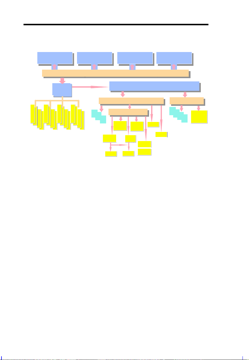
System Architecture
/
Xeon-CPU1
512K/1M/2M Cache
450NX
800MB
MIOC
s
RCGs + MUXs
1234567
9101112131415
2/4 Way Interleave ECC Memory
Xeon-CPU2
512K/1M/2M Cache
64bit @ 100MHz GTL
64bit @ 100MHz GTL
F16 Bus 400MB/s
8
16
1
2
3
32 bit PCI
Slot * 3
Xeon-CPU3
512K/1M/2M Cache
Deschute FSB 800MB/s
Deschute FSB 800MB/s
133MB/s
PCI Bus
PIIX4e
PIIX4e
CD-ROM
ISA
BMIDE HDD
Slot*1
USB
I/O
S I/O
BIOS
BIOS
APIC
APIC
KBC
KBC
I/O
PCI Expander
PCI Expander
Bridge
Bridge
0
VGA
VGA
A.S.M.
R.D.M.
Xeon-CPU4
512K/1M/2M Cache
133MB/s
PCI Bus
PCI Bus
4
5
6
7
bit
32
PCI
Slot * 4
LAN
LAN
1
1
Dual
Ultra2
The system inc ludes a m ai n and m em ory subsystems with four Slot 2
processors and voltage regulators for the processors. The memory
subsystem runs in 100 MHz ti mi ng and has a max im um siz e of up to
4GB.
Six PCI and 1 PCI/ISA shared slots are also incorporated for fast
expandable I/O capabilities.
There are two LVD SCSI (Ultra-2) channels for high performance
storage devi ces and one Narrow SCSI channel f or backup ( i.e., tape
drives) or CD-ROM devices.
A high-speed 10/100Mbi t Ethernet controll er and a PCI VGA dev ice
are also provided.
For more information about the main board see secti on 3.1.
xvi AcerAltos 21000 System Guide
Page 16

Server Management
The system comes with the ASM Pro f eature that m onitors voltage
stability and CPU temperature, prevents data loss by prompt ECC
memory error reporting, maximizes system resources by indicating
the PCI bus utilization, and promotes eff i ci ency by m i ni m i zi ng system
downtime.
A feature related to ASM Pro is Remote Diagnostic Management
(RDM) that permits system diagnosis from a remote site through a
modem. RDM facilitates the fixing of detected problems, changing
system conf igurations or reboot ing in the event of system fai lure.
Hot-swappable Redundant Power Supply Subsystem
The system comes with a power backplane that holds up to three 430watt power supply modules. The power subsystem supports a
redundant conf iguration such t hat even i f one power supply fail s, the
remaining two continue to work t ogether to supply 860-watt power to a
full y-confi gured system . You can also replace a faul ty power supply
module without opening the system housing or shutting down the
system. See section 2.5 for more information.
Hot-swappable Redundant Housing Fan
The system comes with four housing f ans that v entilate the system
housing. In the event t hat any one of the fans f ails to operate, you
can simpl y replace it without shutti ng down the system. See secti on
2.6 for more information.
Security
The system housing comes with mechanical security locks on the
front panel to prevent unauthori z ed ac c ess to the internal c omponents
and system use. Also, a microswitch l ocated on the left side of the
housing panel warns you of i ntrusion.
Introduction xvii
Page 17

The system BIOS protec ts the CMO S dat a and other system sof tware
with a power-on password, keyboard password, setup control, disk
drive control, and monit or c ontrol.
xviii AcerAltos 21000 System Guide
Page 18

Chapter 1 Getting Started
This chapter tells how to install and set up the system. It gives
instructions on how to select a site for the system, pr epar e the system
for use, connect basic peripherals, and start up the system.
1.1 Preinstallation Requirements
1.1.1 Selecting a Site
Before unpacki ng and installing t he system, select a suit able site for
the system f or max im um eff i ciency. The system i s suitable t o set up
in an office environment.
Consider the f ollowing f ac tors when choosing a site for t he system:
•
Near a grounded power outlet
•
Clean and dust-f r ee
•
Sturdy surf ac e free f r om v ibration
•
Well-ventilated and away from sources of heat
•
Secluded from electromagnetic fields produced by electrical
devices such as air conditi oner s, r adio and TV transm itters, etc.
Getting Started 1-1
Page 19

1.1.2 Checking the Package Contents
Check the f ollowing it ems from the package:
•
AcerAlt os 21000 System
•
AcerAlt os 21000 System Guide
•
CD-ROM Driver Kits
•
System keys (hung inside the fr ont panel door)
If any of the above items are7 damaged or missing, contact your
dealer immediately.
Save the boxes and packing materials for future use.
1-2 AcerAltos 21000 System Guide
Page 20
1.1.3 Preparing the System Unit
Do the following to begin setting up the system:
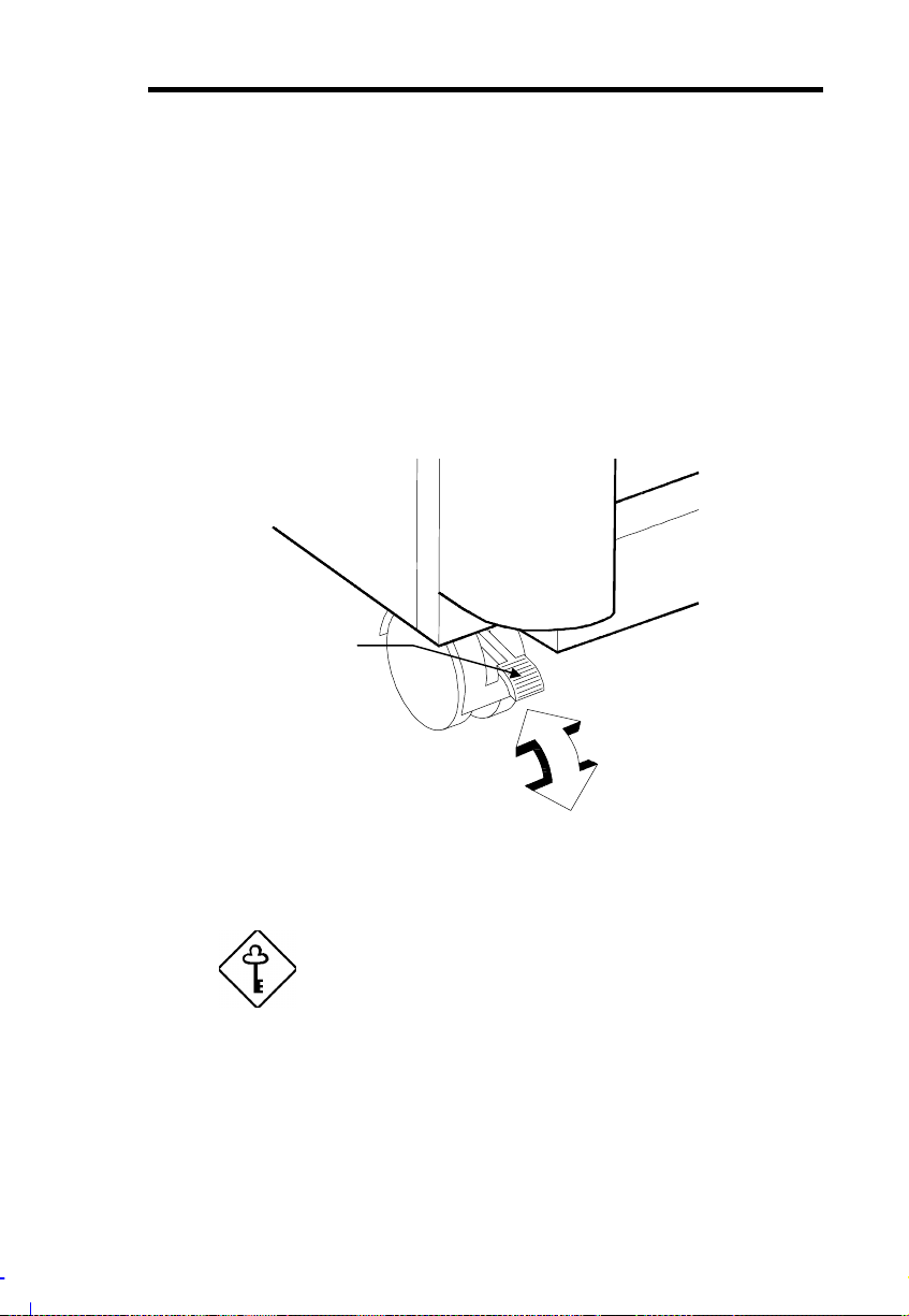
1. Unlock the front wheels and mov e the system to your desired
site.
The system housing design allows for easy transport in spi te of
its size. I t comes with four wheels that facilitate short-distance
transits. The t wo f ront wheels each include a lev er to l ock the
wheels after you have positioned the system into place.
Front Wheel Lever
Unlock
Lock
2. After mov ing, lock the wheels by pressing down the levers.
Make sure to unlock the wheels w hen you want
to move the system again.
3. Connect the system power cabl e into the power supply modul es
on the rear panel. S ee sect ion 2.5.
Getting Started 1-3
Page 21
1.2 Basic Connections
The system unit, keyboar d, mouse, and monitor constitute the basic
system. Before connecting any other peripherals, connect these
peripherals first to t est if the basi c system is running properly.
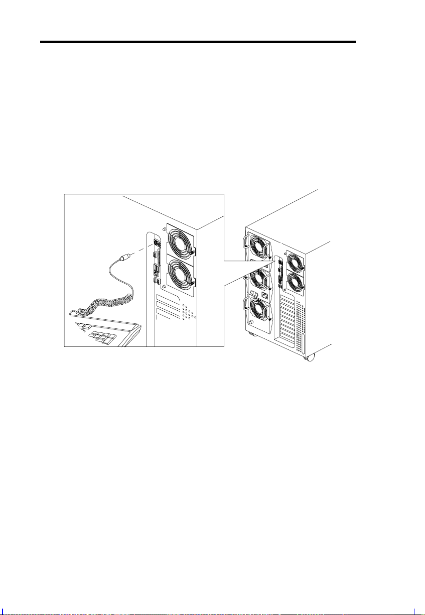
1.2.1 Connecting a Keyboard
1-4 AcerAltos 21000 System Guide
Page 22
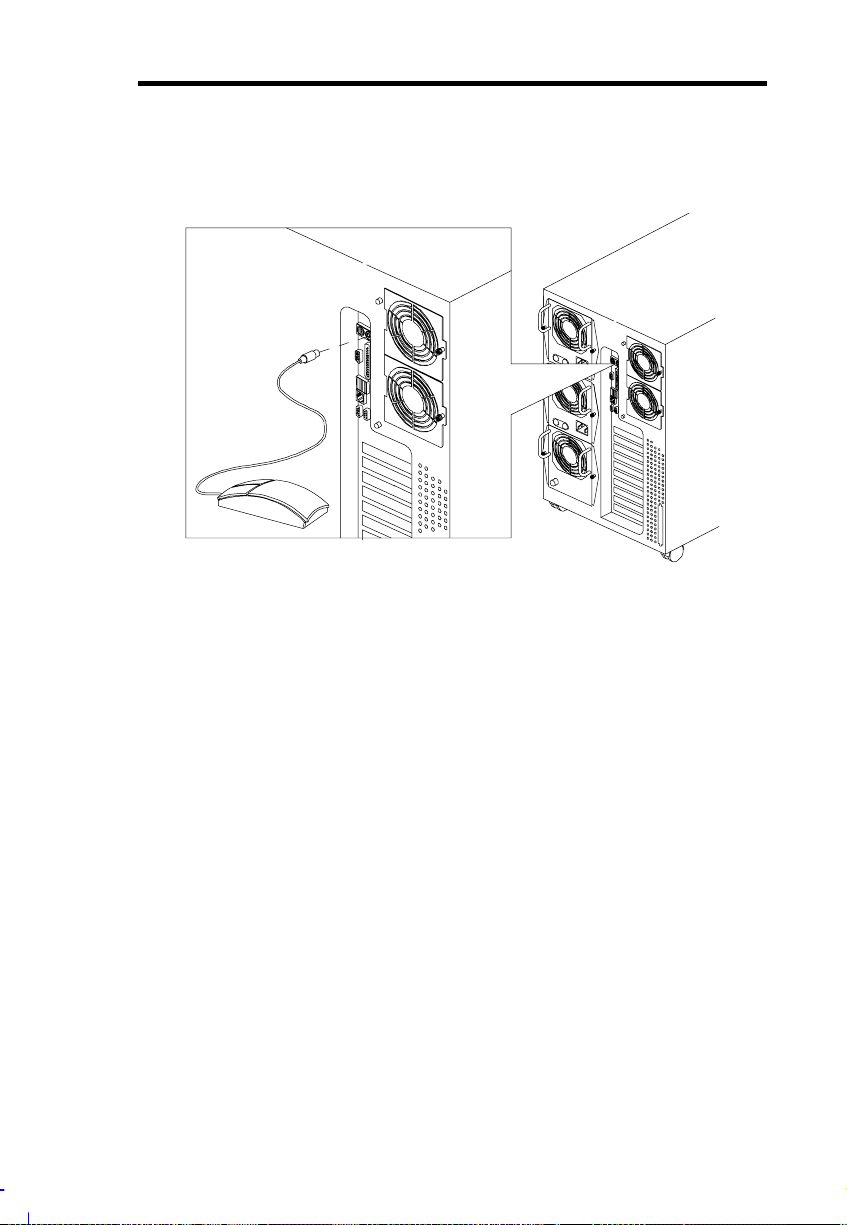
1.2.2 Connecting a Mouse
Getting Started 1-5
Page 23
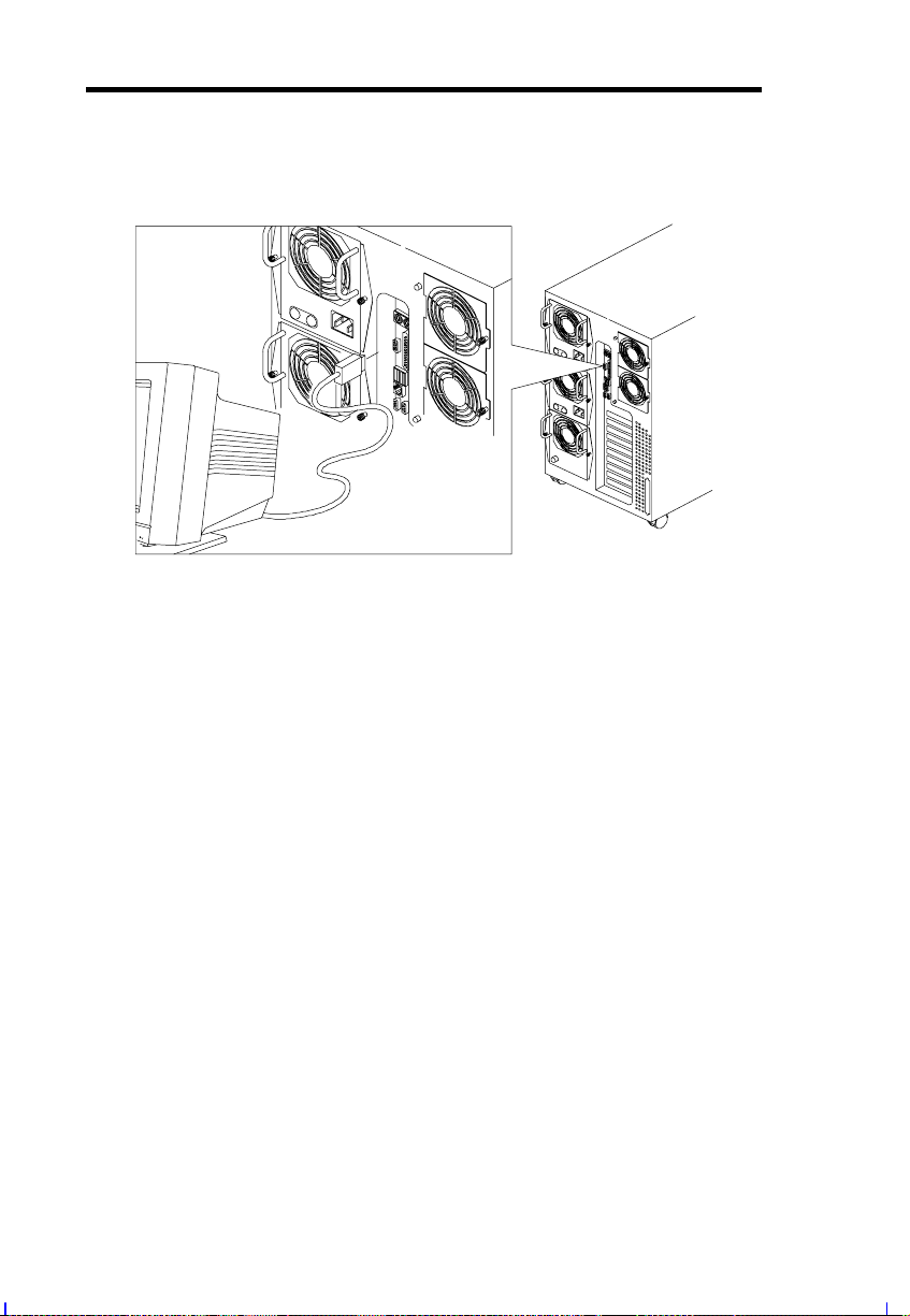
1.2.3 Connecting a VGA Monitor
1-6 AcerAltos 21000 System Guide
Page 24

1.3 System Startup
After making sure that you have set up the system properly and
connected all the required cables, you may now apply power to the
syste m.
Turning On the System Power
To power on the system, press the power switch on the front panel
(see section 2.1.1). The system starts up and displays a welcome
message. After that , a seri es of power-on self-test (PO ST ) m essages
appear on the LCD display screen. The PO ST messages indicate i f
the system is runni ng well or not. See Appendi x A for a list of LCD
messages.
If the system does not turn on or boot after
pressing the power switch, go to the next
section for the possible causes of the boot
failure.
Aside from the self-t est m essages, you can determ i ne i f the system i s
in good condit ion by checking if the followi ng oc c ur r ed:
•
Power indicator LE D on the front bez el light s up (green)
•
Power, Num Lock, and Caps Lock LED indicators on the
keyboard li ght up
•
Power supply power LED locat ed at t he back of the system l i ghts
up (green)
Getting Started 1-7
Page 25
1.4 Power-on Problems
If t he system does not boot af ter you have applied power, check t he
following fact or s that might have caused the boot failur e.
The pointi ng symbol ( ☛ ) indi cates a possible cause of the pr oblem .
The check mark ( ✔ ) t ells you how to correct the problem.
The external power cable may be loo sely connected .
☛
Check the power cable connect ion from the power source to the
✔
power socket on the rear panel. Make sure that each cable is
properly connected to each power supply.
No power comes from the grounded power outlet.
☛
Have an electrician check your power outl et.
✔
Loose or improperly connected i nternal power cables.
☛
Refer to section 2.5.1 for the cable connections and check the
✔
internal cable connections. If you are not confident to perform
this step, ask a qualified technician to help you.
Make sure all power cords are disconnected
from the electrical outlet before performing this
task.
If you have gone through the preceding act ions
and the system still fails t o boot, ask your dealer
or a qualified technician f or as s is tance.
1-8 AcerAltos 21000 System Guide
Page 26
Chapter 2 System Housing
The system housing is a heavy-duty steel chassis in a twin-tower
design. The spacious housing boasts high expansion capability and
flex ible configurati on. It can be converted to fit into a rack mount
cabinet by using t he Rack M ount Ki t . F or m ore i nf orm at ion about t he
rack mount k it, please refer to your dealer.
System Housing 2-1
Page 27
2.1 External and Internal Structure
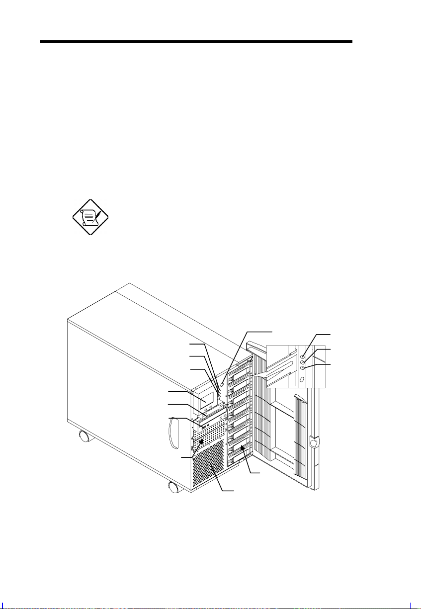
2.1.1 Front Panel
The system front panel is divided into two sections. The left front
panel consists of the diskett e/CD- ROM/ tape dr ive bays, power switch,
LED indicators, and LCD display screen.
The right part contains the hot-swappable SCSI hard disk driv e bays
with 8 drive trays for SCSI dri ves.
One pair of system keys are hung inside the
front panel door. A dditional duplicate keys can
be found at the back of t he system.
7
8
9
10
1
2
3
4
6
5
2-2 AcerAltos 21000 System Guide
11
12
13
Page 28

# Item Description
1 LCD Display Screen Indicates boot status as well as any
BIOS check point errors encountered
upon system initialization. Refer to
section 2.1.3 for more information.
2 3.5-inch Diskette
Drive
3 CD-ROM Dr ive Also a SCSI CD-ROM dr ive comes
4 5.25-inch Drive Bays Two empty 5.25-inch dri ve bays all ow
5 Ventilation Exhausts heat built-up inside the
6 SCSI HDD Bays Eight empty SCSI HDD ba y s a llow
7 Power Switch The power switch turns the system on.
8 System Power LED Lights up (green) when the power is
9 System HDD Ac c ess
LED
10 RDM Active LED Lights up (yellow) when an error
11 SCSI HDD Po wer
Status
12 SCSI HDD Bu s y Lights up when the HDD is c u rrently
13 SCSI HDD Failure Lights up (or ange) when the HDD
A 3.5-inch diskette drive comes with
the basic system.
with the basic system.
installat i on of additional devices.
housing.
installat ion of hot-swap SCSI drives.
on. This also denotes that the system
is running on a good supply of AC
power.
Lights up (green) when at least one of
the hard disks is currently accessing.
condition occurs i n t he system.
Light s u p ( g reen) when the HDD is
connected and ready to go.
accessing.
installed on the backplane board is
bad.
System Housing 2-3
Page 29
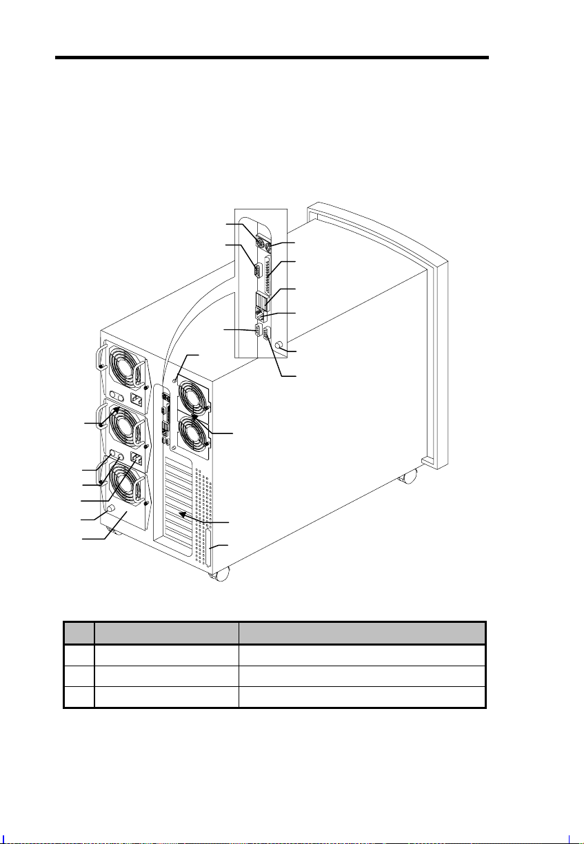
2.1.2 Rear Panel
The rear panel includes the system fan, the connectors for the
keyboard, mouse, VGA moni tor, printer, and serial devices, the slot
openings for expansion boards, and the power supply.
1
2
7
10
3
4
5
6
8
9
11
17
12
13
14
15
16
#
1
PS/2 keyboard port Connects to PS/2 keyboards.
2
Video port Connects to CRT monitors.
3
PS/2 mouse port Connects to the PS/2 mouse.
Item Description
18
19
2-4 AcerAltos 21000 System Guide
Page 30

#
4
Parallel port Connects to parallel devices (e.g.,
Item Description
printer).
5
USB ports Connects to USB devices.
6
LAN port Connects to the network cable.
7
COM 2 port Connects to serial devices (e.g., serial
mouse).
8
Hot-swap redundant
fan fail LED 2
9
COM 1 port Connects to serial devices (e.g., serial
Lights up (green) when the hot-swap
redundant fan is working properly.
mouse).
10
Hot-swap redundant
fan fail LED 1
11
Hot-swappable
redundant Power
Supply Modules
12
Power supply power
LED
13
Power supply fan fail
LED
14
Power cable
Lights up (green) when the hot-swap
redundant fan is working properly.
Removable and installable even when
the system is operating. See section
2.5.
Lights up (green) when the power
supply is on.
Lights up (Yellow) when one of the
power supply fans is faulty
Connects to the power cable.
connector
15
Fan module fail LED Lights up (Yellow) when one or two
fans are faulty.
16
Fan module
(includes two fans)
The fan module is used in place of the
third power supply m odul e if one is not
available.
*
.
*
The powe r supply has two cooling fans. If both fans fail to operate, the power supply
module will shut do wn. The LED indicators of the power supply module will be turned
off.
If the fans are functioning properly and the power supply fails, the fans will keep
operating.
System Housing 2-5
Page 31

#
17
Hot-swap redundant
Fan cage
18
Expansion slots Expansion cards installation. See
19
SCSI knock-out port Allows installation of an external SCSI
Item Description
Allows the system fan to be removed
and installed even when the system is
operating. See section 2.6.
section 2.7.
port.
2.1.3 LCD Display Module
The LCD display is an 8-line by 16-c haract er screen that i ndic ates the
boot status as well as any BIOS c heckpoint error s encountered upon
system initialization. Normally, the system BIOS and the microcontroller firmware send the LCD display messages that appear on
the screen. However, if you hooked up a special purpose driv er to
control the LCD modul e, this driv er defines the messages. See the
driver manual for more information. For a lists of LCD messages
from the system BIOS, please refer to Appendix A.
Main Menu
> H/W Monitor
Event Log
Reset System
Help
<Menu> - Select
<Enter> - E xecute
The main menu consists of four submenus. To access these
submenus, press the Select button (lef t button) to choose and then
press the Enter button (r ight button) to activate the submenu.
2-6 AcerAltos 21000 System Guide
Page 32

H/W Monitor Submenu
> Tem per ature
Voltage
Fan
Power
Fuse
Main Menu
The H/W monitor submenu has f ive it ems. To access t hese i tems,
press the Select button (left button) to choose and then press the
Enter button ( r ight button) to access the menu it em.
Temperature
CPU1: 35 DEG.C
CPU2: 35 DEG.C
CPU3: 35 DEG.C
CPU4: 35 DEG.C
<Enter> Back
This item displays the CPU tem perature reading. I t will only display
the number of av ailable CPUs i nsi de the system. Whenever the CPU
temperat ure ex ceeds the requi red t hreshold, an error m essage will be
displayed and logged into the Event Log for later viewing.
Voltage
CPU1 : 2.00 V
CPU2 : 2.02 V
CPU3 : 2.02 V
CPU4 : 1.98 V
CPU12L2 : 2. 50 V
CPU34L2 : 2. 54 V
<Enter> Next
5V : 5.04 V
5STBY : 4.95 V
3.3V : 3.27 V
3.3STBY : 1.98 V
→
12V : 11.90 V
2.8SCSI : 2.80 V
<Enter> Back
System Housing 2-7
Page 33

This item displays the voltage reading of the CPU, L2 cache, and
others. It will only display the number of available CPU inside the
system. Whenever the voltage exceeds the required threshold, an
error message will be displayed and logged into the Event Log for
later viewing.
Fan
HFAN1: OK
HFAN2: OK
HFAN3: OK
HFAN4: OK
HFAN5: OK
HFAN6: OK
<Enter> Back
This item displays the hot-swap redundant f an condition. It will only
display the num ber of avail able hot-swap redundant fan installed in
the system. If any of the f ans stop working, an error m essage will be
displayed and logged into the Event Log for later viewing.
Power
Power Fan
SPS1: OK OK
SPS2: OK OK
FM3 : OK OK
FM: Fan Module
<Enter> Back
2-8 AcerAltos 21000 System Guide
Page 34

This item displays the hot-swap redundant switching power supply
and fan m odule c ondit i on. I t will only display the number of available
hot-swap redundant switching power supplies and fan modules
installed in the system. I f any of t he SPS or fan modules malfunction,
an error message will be displayed and logged into the Ev ent Log for
later viewing.
Fuse
KB/Mouse : OK
USB1 : OK
USB2 : OK
SCSI1 : OK
SCSI2 : OK
<Enter> Back
This item displays the fuse condit ion for the keyboard, mouse, USB
devi ces, and SCSI devices. If any of the fuses break down, an error
message will be displayed and logged into the Event Log for later
viewing.
Event Log Submenu
Event: 6
12:31 10/29’1998
PS/2 Keyboard
Interface Error
>Down Up Back
The Event Log monitors and records any event that occurs during
boot-up and during t he operation of the system. W henev er an ev ent
occurs, the event log will immediately display the event and then log
it into the ev ent log table.
System Housing 2-9
Page 35

An event is any malf unction or breakdown in the norm al operation of
the system. Eac h event is displayed one by one. To display other
event s, press the Select button (lef t butt on) t o choose down or up and
then press the Enter button (right button) to view other events.
Choose Back to go back to t he main m enu.
Reset System Submenu
RESET SYSTEM?
> Yes
No
This submenu resets the system operation. Press the Select button
(lef t button) to choose and then pr ess the Ent er button (right button) to
confi r m.
Help Submenu
> Navigation
System Tips
System Info.
Main Menu
Provides useful information regarding the operation of the LCD
display screen. Press the Select button (left button) to choose and
then press the Enter butt on ( r ight button) to confi r m.
2-10 AcerAltos 21000 System Guide
Page 36

Replacing the LCD Display Screen
The system housing can be configured as a stand-alone tower
housing or a rack mounted housing (please refer to the AcerAltos
Rack Installation Guide for more information on rack installation).
Wi th each confi gurati on, the LCD di splay screen is pl aced dif f erently .
For more information about the rack mount installation and
confi gur ation, please refer to its user’s guide.
To replace t he LCD display screen:
1. Turn off the power to t he system unit and unpl ug all cables.
2. Carefully pull out the LCD displ ay screen. There is a connector at
the back of the LCD display.
3. Disconnect t he LCD c onnec tor.
4. Connect the LCD connector at the back of t he new LCD display
screen.
5. Attach the LCD display screen to t he housi ng.
System Housing 2-11
Page 37

2.1.4 Internal Components
The housing is symmetrically div ided into the left and right panels.
The system’s internal components are accessible through these
panels.
Left Panel
The main part of the left panel houses the system board, memory
board, and expansion boar ds. On the rear end of the lef t panel are
the keyboard, mouse, video, parallel, and serial ports, and the slot
openings for installation of IS A and P CI expansion boards.
The front panel display occupies the upper front section of the left
panel. The secti on below the fr ont panel displ ay acc omm odates one
3.5-inch and three 5.25-inch drives. These devices on the front
section are ex ternally ac c essible.
Here is a diagram of the system com ponents on the lef t panel of the
system housing.
Hot-swappable
Redundant Fans
Thermal Air Guide
Expansion
Slots
System Board and
Memory Board
Hot-swappable
Redundant Fans
5.25-inch
Drive Bays
LCD Display
Screen
3.5-inch
Drive Bay
Ventilation
2-12 AcerAltos 21000 System Guide
Page 38

Right Panel
The power subsystem fills up most of the rear right panel. It consi sts
of a power backplane boar d and a metal rack t hat holds up to three
430-watt redundant power supply modules. A f an module should be
install ed whenever a power supply is rem oved t o provi de the system
with regular cooling. See section 2.5 for details on the power
subsystem.
The lower section allows installat ion of a S CS I backplane board and a
set of eight hot-swappable SCSI dri ve tray s.
Here is a diagram of the components that reside on the right panel.
SCSI Drive Tray
Bays
SCSI Backplane
Board
Power Supply
Module Bays
Power Supply
Backplane Board
System Housing 2-13
Page 39

2.2 Opening the Housing Panels
The system housing has one f ront door and two side panels. Always
observe the following ESD (electrostatic discharge) precautions
before i nstalling any system component:
1. Do not remove any system com ponent from i t s packaging unl ess
you are ready to i nstall it .
2. Wear a wrist grounding strap before handling electronic
components. Wrist grounding straps are available at most
electronic component stor es.
DO NOT attempt the pr ocedures in t he follow ing
sections unless you are confident of your
capability to perform them. Otherwise, ask a
service technician for assistance.
2.2.1 Removing the Left and Right Panels
A microswitch is allocated on the lef t side of the housing panel. It
helps indicate whether the panel is removed or intact.
To remove the l eft or right panel:
1. Turn off the power to t he system unit and unpl ug all cables.
2. Place the system unit on a flat, steady surface and lock the
wheels by pressing down the lever s.
3. Remove the screws of the left or right panel. Set the screws
aside. You will need them when replacing t he panels.
4. Pull out the panel and detach it.
2-14 AcerAltos 21000 System Guide
Page 40

Right Panel
Left Panel
2.2.2 Opening the Front Panel Door
A security l ock secures the f ront door to protect against unauthori zed
access.
To open the front door:
1. Insert the key to t he l ock and t urn i t cl ock wise until i t poi nt s to t he
unlocked ic on.
System Housing 2-15
Page 41

2. Pull open the front door .
Removing the Front Panel Door
The doors are attached to the main housing by screwless hinges.
Follow these steps to remove t he door :
1. Unlock the door with the key (when necessary).
2. Open it to more than a 45° angle.
3. Lift it up a little, then move it away from the housi ng.
2-16 AcerAltos 21000 System Guide
Page 42

2.3 Installing and Removing Storage Devices
The housing supports one 3.5-inch and f our 5. 25-i nch i nter nal stor age
devi ces. The empty drive bays on the upper front panel al l ows you to
install additional drives such as a CD-ROM drive, digital audio
tape (DAT) drive or another hard disk drive.
Your basic system comes with a CD-ROM drive
and a 3.5-inch diskette drive already installed.
2.3.1 Installing and Removing a 3.5-inch Storage
Device
The housing comes with a driv e guide f or install ing 3.5-inch storage
devi ces.
To i nstall a 3.5-inch storag e device:
1. Open the front panel door and remove the left panel. See
section 2.2 for more information on opening t he housi ng panels.
2. Attach the dr ive guide to the ex ternal device as shown below.
System Housing 2-17
Page 43

3. Secure the drive with f our screws.
4. Insert the drive into the bay.
2-18 AcerAltos 21000 System Guide
Page 44

5. Sec ure the dri v e with a screw. The screw hole is l ocated on the
side of the housi ng.
6. Connect the power cable and signal cable to the ex ternal device.
7. Close the left panel.
To remo ve a 3.5-inch storage device:
1. Open the front panel door and remove the l eft panel. See sect ion
2.2 for more information on opening the housing panel s.
2. Disconnect the power and signal cabl es.
3. Detached the external dev ice by remov ing the screw located on
the side and then gently pulli ng out the dev ice.
4. Remov e the four screws and detach the 3.5-i nch drive f rom the
drive guide.
System Housing 2-19
Page 45

2.3.2 Installing and Removing a 5.25-inch Storage
Device
The housing comes with a dr iv e gui de for instal ling 5.25- inch inter nal
storage devices.
To i nstall a 5.25-inch storag e device:
1. Open the front panel door and remove the left panel. See
section 2.2 for more information on opening t he housi ng panels.
2. Remove t wo screws to detach the metal cover.
2-20 AcerAltos 21000 System Guide
Page 46

3. Attach the drive guides on the sides of the external device as
shown below.
4. Insert the drive into the bay.
System Housing 2-21
Page 47

5. Secure the drive with two screws as shown below.
6. Connect the power cable and signal cables to the ext er nal device.
7. Close the left panel.
To remo ve a 5.25-inch storage device:
1. Open the front panel door and remove the l eft panel. See sect ion
2.2 for more information on opening the housing panel s.
2. Disconnect the power and signal cabl es.
3. Det ached the ex ternal dev i ce by rem ov ing the screws and gently
pulli ng out the dev ice.
4. Remove four screws to detach the dri ve from the drive guide.
2-22 AcerAltos 21000 System Guide
Page 48

2.4 Installing a Hot-swappable SCSI Drive
Remove all jumper connectors on the SCSI
drive before installing it into the system. Also,
for Single-Ended (SE) SCSI drives, remove the
terminator jumper before connecting the SCSI
drive to the system. For the location of the
jumper connectors and the terminator jumper,
please refer to your hard drive’s instructions or
manual.
The system supports up to ei ght hot-swappable drive trays.
Follow these steps to install a hot-swap SCSI drive:
1. Open the front panel door.
2. Use your finger to rel ease the dri v e t ray as shown below and then
pull it out.
System Housing 2-23
Page 49

3. Secure the hard disk drive with four screws.
4. Install t he tray int o the dr ive bay, pushing i t gent ly unt il i t reaches
the connector on t he bac k plane board.
5. Push the lever back until it c licks into place.
2-24 AcerAltos 21000 System Guide
Page 50

2.5 Installing and Removing a Hot-swappable
Redundant Power Supply Module
The power subsystem consists of a power backplane and hotswappable power supply modules. These components are held in
place by a m etal rack enclosure.
The backplane and t he rack allow instal lati on of up to t hree 430-watt
power supply modules in a hot-swappable redundant conf i gurat ion. A
redundant power configuration enables a fully-configured system to
continue runni ng even if one power supply fail s. The remaini ng two
power supply modules still satisfy up to 860-watt of system power
requirement.
If fans fail to operate, the power supply
module will shut down. The LE D indicator s of
the power supply m odule will be turned off.
If the fans are functioning properly and the
power supply fails, the fans will keep
operating.
The power subsystem prov ides a standby cur rent and a r em ote on/ of f
feature to support cold reboot f rom a rem ote site. S ee Chapter 5 for
an overview of the remot e diagnostic m anagement (RDM).
The power supply subsystem should supply a minimum 860W (2
power supply modules) DC power to the whol e system . An addi ti onal
power supply module can also be added for fail-safe redundancy.
System Housing 2-25
Page 51

To Install a power supply module:
1. Insert the power supply into the housing.
Make sure that the power supply is properly
inserted.
2-26 AcerAltos 21000 System Guide
Page 52

2. Secure the power supply wit h the screw knobs on both sides.
3. Connect a power cable to the power. Plug it into an electrical
socket. You will see a green light when the power supply is
functioning properl y .
System Housing 2-27
Page 53

The power supply supplied with the system
accepts input voltage of 100V~240V, 50~60Hz.
To remo ve a power supply module:
1. Detach the power cable from the electrical outlet and also from
the power supply. The power indicator light turns off.
2. Unscrew the screw knobs and carefull y pull out the power supply
until it detaches f r om the housing.
Make sure the power supply subsystem is
supplying a minimum of 860W (2 pow er supply
modules) to the system.
2-28 AcerAltos 21000 System Guide
Page 54

2.6 Installing and Removing a Hot-swappable
Redundant Housing Fan
Four housing f ans are distribut ed inside t he housing to cool down the
system. They are hot-swappable and redundant. You can simply
take one out and put a new one in if a f an f ail s to operate. You don’t
even have to shut down the system.
To ch ange a rear hot-swap housing fan:
1. Turn the screw knob counterclockwise to open the housing fan
cage.
System Housing 2-29
Page 55

2. Push down the clip and pull out the housing fan.
Clip
3. Sli de in a new housing fan. The power i ndicator lights up.
4. Close the housing fan cage and tur n the screw knob clockwise to
lock it.
2-30 AcerAltos 21000 System Guide
Page 56

To change a front hot-swap housing fan:
1. Remov e the lef t panel. See section 2. 2 for more inform ation on
opening the housing panel s.
2. Push down the clip and pull out the housing fan.
Clip
3. Insert a new one.
4. Close the left panel.
System Housing 2-31
Page 57

2.7 Installing an Expansion Board
Follow these steps to install a PCI expansion board:
1. Rem ove the lef t panel of the housing. See section 2. 2 for more
infor mation on opening the housing panels.
2. Remove the bracket cover opposite an em pt y PCI slot. S av e t he
screw for later use.
2. Align t he boar d with the slot.
3. Insert the board i nto the slot until it c ompletel y fits i n.
4. Secure the board with a screw.
2-32 AcerAltos 21000 System Guide
Page 58

5. Follow the sam e steps when installi ng an ISA board. Just make
sure that you rem ove the brac k et cover opposi te an ISA slot.
System Housing 2-33
Page 59

2.8 Removing and Installing the
Thermal Air Guide
On the left side of the housing, a m etal therm al air guide di rects the
hot air from the i nside to the f an ex hausts on the rear of the housing.
The air guide helps in maintaining good air circulation within the
housing.
To avoid electric shock and damage to the
system, DO NOT perform the following
procedure while the system is ON.
2.8.1 Removing the Thermal Air Guide
Follow these steps to remove t he thermal air guide:
1. Unplug all power cables from the wall socket.
2. Open the left panel door. Refer to section 2.2 f or instruct ions on
opening the door.
3. Rem ov e the two screws that secure the air gui de to the housing.
Save the screws.
4. Careful ly remove the ai r guide from the housing and set it asi de.
2-34 AcerAltos 21000 System Guide
Page 60

2.8.2 Reinstalling the Thermal Air Guide
Follow these steps to replace the thermal air guide back into the
housing:
1. Position the air guide in it s pl ac e as shown below.
2. Make sure that the air guide f its properly in place.
System Housing 2-35
Page 61

3. Secure the air guide with two screws.
4. Reattached the left panel door.
2-36 AcerAltos 21000 System Guide
Page 62

2.9 Cable Connections
The power backplane is com plete with connectors to accom modate
the power cables for all the system components. Each cable is
labeled with a c able num ber , and each c able’s poi nt (head and tai l ) is
also numbered, because each cable can only fi t one way and is not
interchangeable. For a list of all the cables and their respective
connectors, please refer to the power cabl e list in t his section.
The figure below illustrates the power cables that connect to the
system board and the SCSI backplane board.
SCSI Backplane
Board
C4:P
CN9
CN# - System board connectors
C# - Cable number
P# - Cable point (head and tail)
Power Backplane Board
C1:P
C2:P
C3:P
C4:P
C1:P2
CN15
C2:P2
CN15
C3:P2
CN22
System Board
System Housing 2-37
Page 63

All power cables come with yellow stickers
telling you which connectors to attach to the
system board and to the power backplane.
Make sure to connect the cables correctly;
otherwise, the system may not power up.
Power Cable List
CN# - Sy stem board connectors
C# - Cable number
P# - Cable point (head and tail)
1. System B oar d and S CS I Backplane Board P ower Connect ion
Cable # System Board SCSI
Backplane
Board
Power Backplane
C1 CN8 (C1:P2) J1 (C1:P1)
C2 CN15 (C2:P2) J2 (C2:P1)
C3 CN22 (C3:P2) J3 (C3:P1)
C4 CN9 (C4:P5) J4 (C4:P6)
2. I2C Status Connector
Cable # System Board SCSI Backplane Board
C5 CN50 CN10
3. LCD Display Module Cable Connection
Cable # System Board LCD Display Module
C6 CN16 CN1
4. Switchi ng P ower Supply Status Connector
Cable # System Board SCSI Backplane Board
C7 CN28 J5
Board
2-38 AcerAltos 21000 System Guide
Page 64

5. Floppy Disk Drive, IDE Devices, and SCSI Device Connectors
Cable # System Board Devices
C11 CN39 Floppy Di sk Drive
C12 CN42 IDE Devices
C13 CN41 50-pin SCSI Devic es
6. LVD SCSI Channel A and B Connector
Cable # System Board SCSI Backplane Board
C14 CN48 CN12
System Housing 2-39
Page 65

Chapter 3 System Boards
The system boards consist of the main board, the mem ory board, the
SCSI backplane board, and the LCD display modul e. This chapter
discusses the system board configurations in detail.
3.1 Main Board
The mai n boar d has the foll owing major components:
•
Four Slot 2 CPU (Central Processing Unit) connectors that
support one, two, three, or four Intel Penti um II Xeon proc essors
and the next gener ation of P entium proc essors:
• Intel Pentium II Xeon running at 400 with integrated 512K
and 1MB L2 write-back c ac he
• Intel Pentium II Xeon running at 450 with i ntegrated 512K,
1MB, and 2MB L2 writ e- bac k c ac he
• One VRM (Voltage Regulator Module) for each CPU and
one VRM for the L2 cache of t wo CPUs
•
256-KB Flash ROM for system BIOS
•
Supports two PCI buses through one PXB (PCI Expander Bridge)
•
System clock/calendar with battery backup
•
One 68-pin Wide SCS I connector for each SCSI channel
• One narrow SCSI connector for connecting legacy SCSI
devices, such as SCSI CD-ROM, DA T drives, etc.
•
Serv er management functi ons
•
PCI SVGA on- boar d, supports up to 1024 x 768 resolut ion
• Onboard 2MB V GA RAM
•
Enhanced IDE hard di sk and diskette drive int er faces
•
PCI local bus IDE (Integrat ed Devic e E lectronics) controller
System Boards 3-1
Page 66

•
One PCI enhanced IDE interfaces that support up to two IDE
devices
•
One ISA and seven PCI slots (one PCI-/ISA-shared)
•
One dual channel PCI Ultra/Wide and LVD (Ultra2) SCSI
controller
•
I2O ready
•
One 10/100 Ethernet LAN chip on board with W ake-up on LAN
(W OL) funct ion
•
External ports
•
PS/2 key boar d and mouse ports
•
Two buffered high-speed serial ports
•
One SPP/ECP/EPP high-speed parallel port
•
Two USB ports
•
VGA port
•
Front panel LCD/LED int er face
3-2 AcerAltos 21000 System Guide
Page 67

3.1.1 Layout
33
34
1
2
3
4
5
6
7
10
32
31
30
29
28
27
23
22
25
24
21
26
20
8
19
18
9
17
16
11
12
13
15
14
1. PS/2 Mouse port
2. PS/2 Keyboard port
3. Video port
4. Parallel port
5. USB ports
6. LAN port
7. COM2 port
8. LAN controller chipset
9. COM1 port
10. VGA controller chipset
11. PCI slots 1 to 7
12. BIOS chipset
13. ISA slot
14. IRQ Mapper chipset
15. PCI Expander Bridge (PXB) chipset
16. Battery
17. AIC7896 SCSI controller
18. Wide SCSI interface channel B
*
19. Wide SCSI interface channel A
20. Narrow SCSI interface
21. IDE connector
22. FDD connector
23. Buzzer
24. PIIX4e (PCI to ISA Bridge) chipset
25. Memory board slot
26. Memory and I/O Controller (MIOC)
27. RDM connector
28. Front panel bard connector
29. Power supply status/control
connector
30. Power connector 3
31. Power connector 2
32. Power connector 1
33. Slot 2 sockets 1 to 4*
34. VRM sockets 1 to 6*
*
From top to bottom.
System Boards 3-3
Page 68

3.1.2 Jumpers and Connectors
The figure below shows the jumper and connector locations on the
system board.
The blackened pin of a jumper or connector
represents pin 1.
3-4 AcerAltos 21000 System Guide
Page 69

Jumper Settings
Jumper Setting Function
BIOS Logo
JP2
1-2
*
2-3
JP5 1-2
2-3*
JP19 5-6 & 2-3*
4-5 & 1-2
JP20 1-2*
2-3
Acer
OEM
Password Security
Check password
Bypass password
Housing Door Open Alarm
Use LM80 Only
Reserved
VGA
Auto VGA selection
Disable on-board VGA
Connector List
Connector Function
CN1 HDD LED connector
CN3 Reserved
CN4 Voltage Regulator Module (VRM) 1 connector
CN5 Fan connector 4
CN7 Fan connector (reserved)
CN8 Power cable connector
CN10 Slot 2 CPU 1 thermal connector
CN11 Voltage Regulator Module (VRM) 2 connector
CN12 PS/2 Keyboard (below) & PS/2 Mouse (above) port
CN13 Power LED connector
CN14 Slot 2 CPU 2 thermal connector
CN15 Power cable connector
*
Default setting
System Boards 3-5
Page 70

Connector Function
CN16 LCD (front panel) connector
CN17 USB connector
CN18 Voltage Regulator Module (VRM) 3 connector
CN19 Slot 2 CPU 3 thermal connector
CN20 Voltage Regulator Module (VRM) 4 connector
CN21 Parallel port (t op) , VGA port (bottom)
CN22 Power cable connector
CN23 Voltage Regulator Module (VRM) 5 connector
CN24 LAN (RJ-45) port
CN25 Reserved
CN26 Slot 2 socket 4 thermal connector
CN27 Fan connector for Slot 2 socket 3
CN28 Power status/control connector
CN29 Voltage Regulator Module (VRM) 6 connector
CN31 & 32 RDM (Remote Diagnostic management) connector
CN33 Fan connector (reserved)
CN34 RDM LED connector
CN35 HDD act ivity indication from Add -on card
*
CN36 Housing Intrusion Switch connector ( l eft panel)
CN37 Fan connector 2
CN38 Reserved
CN39 FDD connector
CN40 Power button connector
CN41 Narrow SCSI connector
CN42 IDE connector
*
These connectors (CN35 and CN44) are used for accepting the HDD activity information
from the storage adapters. If the storage adapter's information is not passed to the main
board via these connectors, the activities of the HDD which w as connected to the a dapter
will not be reflected on LCD Display Module .
3-6 AcerAltos 21000 System Guide
Page 71

Connector Function
CN43 Feature connector
CN44 HDD act ivity indication from Add -on card (see
CN35)
CN45 Fan connector 1
CN46 Wake-on-LAN connector
CN47 Wide SCSI connector channel B
CN48 Wide SCSI connector channel A
CN49 Serial ports 1 (above) and 2 (below)
CN50 Backplane board connector (connects to CN10)
JP1 CPU 1 fan connector
JP10 CPU 2 fan connector
JP12 CPU 3 fan connector
JP13 CPU 4 fan connector
JP14 MIOC chipset fan connector
JP18 PXB U64 fan connector
JP21 Reserved
JP22 Reserved
JP23 Reserved (Right door intrusion connector)
3.1.3 Installing and Removing an Intel Pentium II
Xeon CPU
Intel’s Penti um II Xeon CPU is a Slot 2 processor that uses a 330contact connect or which i s a bit l onger that a Sl ot 1 processor. O ther
than the size, t he m aj or i m provement of the S lot 2 processor is at t he
L2 cache. Pentium II Xeon processors access the L2 cache at f ull
clock speed, 400 MHz or 450 MHz, whereas a Slot 1 processor
accesses the L2 at only half the CPU’s clock speed. Thus, Slot 2
processor signifi cant l y boost perf or m ance and speed. Here are som e
of the ot her features of the Pentium II Xeon processor:
0.25 micron P6 microarchitecture core
•
System Boards 3-7
Page 72

• 100 MHz System Bus and 60ns buffered EDO memory support
• New System managem ent f eatures v ia S ystem Management bus
(Smbus)
The system board comes with four Slot 2 CPU sockets and their
respective retention mechanism to secure the CPU.
Installing an Intel Pentium II Xeon processor
Follow these steps to install a Pentium II Xeon processor:
1. At tach the fansink modul e to the Pentium II Xeon processor and
secure it with four screws.
2. Rem ove the lef t panel of the housing. See section 2. 2 for more
infor mation on opening the housing panels.
3. If there is an existi ng terminat ion board instal led in the CPU sl ot,
remove it. Refer to section 3.1.4 for removing a termination
board.
3-8 AcerAltos 21000 System Guide
Page 73

4. Insert the Pentium II Xeon processor into an empty Slot 2 socket.
OO
5. Carefully press down the Pentium II Xeon processor until it is
properly i nsert ed.
6. Use the retention mechanism cover to secure the processor as
shown below.
The retention mechanism cover only fi ts one way. Both shafts of
the retention mechanism and the retention mechanism cover
have a O and a OO sign. Match the O on t he cover with the O
on the retention mechani sm f i rst, then hook ed them t ogether and
then insert the OO side to the retention mechanism and make
sure they are clipped.
System Boards 3-9
Page 74

7. Connec t the heatsink cables to the m ain board. Ref er to secti on
3.1.2 f or the locati on of the thermal and f an c onnec tors.
Refer to the VRM LED guide (section 3.1.5) for
installing VRMs. A V RM LE D with green light indic ates
that a VRM has t o be ins talled in its socket.
3.1.4 Installing and Removing the Termination
Board
When you are not using all the Slot 2 sockets, you must install a
termination board i nto each empty sl ot.
Installing a Termination Board
Follow these steps to install the ter mination board:
1. Position t he termination board over the empt y sl ot.
2. Carefully insert the golden fingers of the termination board into
the slot until the board fits com pletely.
OO
3. Use the retention mechanism cover to secure the processor by
pressing it down until it loc k s.
3-10 AcerAltos 21000 System Guide
Page 75

The retention mec hanism cov er onl y f its one way. Both shaf ts of
the retention mechanism and the retention mechanism cover
have a O and a OO sign. Matc h the O on the cover with the O on
the retention mechanism first, then hooked them together and
then insert the OO side to the retention mechanism and make
sure they are clipped.
Removing an Intel Pentium II Xeon processor
Follow these steps to remove a Pentium I I Xeon processor:
1. Remove the thermal and fan connector and then unclip the
retention mechanism c over.
System Boards 3-11
Page 76

2. Flip up both of the pl astic ears of t he Penti um II Xeon processor.
This procedure detac hes the pr oc essor from the socket .
3. Carefully lift up the Pentium II Xeon processor and remove it.
3.1.5 Installing and Removing a VRM (Voltage
Regulator Module)
Each Pentium II Xeon processor requires two VRMs (Voltage
Regulator Modules), one for t he pr oc essor and another one for the L2
cache. However, two L2 caches share one VRM. If y ou are i nstalling
two Pentium II Xeon processor, you need three VRM s: t wo VRMs for
each processor and one VRM for both of the L2 cache to share.
Refer to section 3.1.2 for the location of the VRM sockets. The
following table shows the VRM socket allocation:
VRM Socket Slot 2 Socket
VRM Socket 1 (CN4) CPU 1
VRM Socket 2 (CN11) L2 cache of CPU 1 and 2
VRM Socket 3 (CN1 8 ) CPU 2
VRM Socket 4 (CN2 0 ) CPU 3
VRM Socket 5 (CN23) L2 cache of CPU 3 and 4
VRM Socket 6 (CN2 9 ) CPU 4
3-12 AcerAltos 21000 System Guide
Page 77

VRM LED
There is one LED indicator for each VRM module. Before system
power-on, an LED would l ight up (green) i f a VRM i s required for the
processor or the L2 cache. If you see a red li ght af t er power-on, then
it m eans that the VRM is bad and that it needs to be replaced.
To install a VRM:
1. Find an empty VRM socket and fli p the lev er bac k .
2. Carefully insert a VRM into the socket. This process will
automatically lock the VRM in place.
To remo ve a V RM :
1. Push down both the locking mechanisms.
2. Take out t he V RM .
System Boards 3-13
Page 78

3.2 Memory Board
The memory board comes al ready instal led wit h the basic system . A
total of 16 168-pin DIMM sockets reside on the board. The sockets
accept 64-MB, 128-MB, and 256-MB DIMMs f or a max im um of 4 GB
memor y conf igur ati on. T he Mem ory Control I nterface consists of one
RAS/CAS Generator (RCG) and two Data Path Multiplexer (MUX)
chipsets which belong to the Intel 450NX chi pset.
Each of t he sockets represents one independent bank, which allows
you to instal l DIMMs with differ ent capacities to form a c onfigurat ion.
3.2.1 Layout
MUX chipset
RCG chipset
MUX chipset
3.2.2 Memory Configurations
Ever y f our sl ots of m em ory ( slot 1- 4, 5-8, 9-12, and 13-16) f or m s a 4way interleav ing group. You m ust conf igure four identical EDO/ECC
buff ered DIMMs in a group for your system to work properl y. Please
contact your dealer f or a l i st of qual i f i ed DIMM s. Use of non- quali f i ed
DIMMs may cause your system to malfunction.
The table below shows the working memory configurations.
3-14 AcerAltos 21000 System Guide
Page 79

Bank 0 Bank 1 Bank
2-3
Bank
4-7
Bank
8-11
Bank
12-15
Total Memory
64M*1 64M*1 64M*2 256M
64M*1 64M*1 64M*2 64M*4 512M
64M*1 64M*1 64M*2 64M*4 64M*4 768M
64M*1 64M*1 64M*2 64M*4 64M*4 64M*4 1024M
64M*1 64M*1 64M*2 64M*4 128M*4 1024M
64M*1 64M*1 64M*2 64M*4 128M*4 128M*4 1536M
128M*1 128M*1 128M*2 512M
128M*1 128M*1 128M*2 128M*4 1024M
128M*1 128M*1 128M*2 128M*4 64M*4 1280M
128M*1 128M*1 128M*2 128M*4 64M*4 64M*4 1536M
128M*1 128M*1 128M*2 128M*4 128M*4 1536M
128M*1 128M*1 128M*2 128M*4 128M*4 128M*4 2048M
256M*1 256M*1 256M*2 1024M
256M*1 256M*1 256M*2 256M*4 2048M
256M*1 256M*1 256M*2 256M*4 64M*4 2304M
256M*1 256M*1 256M*2 256M*4 64M*4 64M*4 2560M
256M*1 256M*1 256M*2 256M*4 128M*4 2560M
256M*1 256M*1 256M*2 256M*4 128M*4 128M*4 3072M
256M*1 256M*1 256M*2 256M*4 256M*4 3072M
256M*1 256M*1 256M*2 256M*4 256M*4 256M*4 4096M
3.2.3 Removing and Installing the Memory Board
Follow these steps to remove t he memory boar d:
1. Remove t he si de panel, see section 2.2. 1 for mor e instructions.
2. Remove the thermal air guide, see section 2.8 for more
instructions.
3. Gently pull out the memory board using both hands.
System Boards 3-15
Page 80

Follow these steps to install the memory board:
1. Align the memory board with the memory board slot on the
system board.
Install the memory board with the component
side up.
2. Insert the board i nto the slot until it fits into place.
3. Insert one end of the metal brac ket into the hole l ocated at the
back of t he housi ng.
4. Align t he c lamp rai l with the board edge.
5. Secure the m etal bracket with a screw as shown below.
3-16 AcerAltos 21000 System Guide
Page 81

3.2.4 Installing and Removing a DIMM
Installing a DIMM
To install a DIMM, al ign it with the socket and press it down unti l the
holding clips secure the DIMM in place.
The DIMM socket is slotted to ensure proper
installation. If you slip in a DIMM but does not
completely fit, you may have inserted it the
wrong way. Reverse the orientation of the
DIMM.
Removing a DIMM
To remove a DIMM, press the holding clips on both sides of the
socket outward to release the DIMM.
Place your forefingers on the top of the DIMM
before you press the holding clips to gently
disengage the DIMM from the socket.
System Boards 3-17
Page 82

3.3 SCSI Backplane Board
The SCSI backpl ane board provi des a convenient i nterface between
the SCSI dri ves and the system board. It includes ei ght SCSI drive
slots to accommodate the drive trays and two SCSI channels to
connect to the system board or SCSI controller boar d.
3.3.1 Features
The backplane board has the foll owing major features:
•
“Hot-swap” feature that allows replacem ent of a defective hard
drive even while the system is in full operation. This feature
requires a RAID cont r oller board and RAI D dr iver s.
•
2 channel configurations which support 4 SCSI hard drives per
channel configurati on
•
Indicates hard disk drive failure through a f r ont panel board LED
•
Supports ultra-2 SCSI SCA (Single Connector Att achment) disk
driv es
•
SCSI ID strapping that allows wide SCSI HDD ID configuration
through the backplane switches, instead of configuring the
individual dr ive IDs
3-18 AcerAltos 21000 System Guide
Page 83

3.3.2 Layout
CN10
2
C connector
: I
CN12
: SCSI
SCSI Slot ID
Switches
CN14
LED Boards
: Connects to
CN9
: Power
CN11
: Combined
LED connector
CN13
: SCSI
Channel B
CN1-CN4
SCSI Driv e Slo t 1 to
CN5-CN8
SCSI Driv e Slo t 5 to
: Channel A
: Channel B
System Boards 3-19
Page 84

3.3.3 Hard Disk ID Switch Settings
The backplane board c omes with eight ID switc hes that allow you to
define up to 16 hard disk IDs.
The illustration below shows the switch settings with the
corresponding hard disk I Ds.
ID Switch
Setting
Hard Disk ID
Hard Disk ID
ID Switch
Setting
3-20 AcerAltos 21000 System Guide
Page 85

3.3. 4 Dual Channel Configuration
In a dual-channel configuration, channel A supports the devices in
slots 1 to 4, and channel B support s the devic es i n sl ots 5 to 8.
CN48
: SCSI Channel
A connector
CN12
: SCSI Channel
A connector
System
Board
CN47
: SCSI Channel
B connector
SCSI Backplane
Board
CN13
: SCSI Channel
B connector
SCSI channel A
for Slot 1 to 4
SCSI channel B
for Slot 5 to 8
System Boards 3-21
Page 86

3.4 LCD Display Module
The system includes a front panel modul e that serv es as an interf ace
to the internal system components and relays external messages
through the LCD display screen. Refer to section 2.1.3 for more
information.
The fi gure bel ow shows the LCD display m odule connec ti ons wit h t he
system board.
CN16
CN1
3-22 AcerAltos 21000 System Guide
Page 87

Chapter 4 BIOS Utility
The BIOS Utility allows you to view your system’s configuration
settings.
Most systems are already configured by the manufacturer or the
dealer. There is no need to run Setup when starting the computer
unless you get a Run Setup m essage.
The Setup program loads configuration val ues into the bat t ery-backed
nonvolatile memory called CMOS RAM. This memory area is not
part of the system RAM.
If you repeatedly receive Run Set up messages,
the battery may be bad. In this case, the
system cannot retain configuration values in
CMOS. Ask a qualified technician for
assistance.
BIOS Utility 4-1
Page 88

4.1 Entering Setup
To enter Setup, press the key combi nation + + .
You must press + +
system is booting. This key combination does
not work during any other time.
The BIOS Utility main menu then appears:
BIOS Utility
System Information
Product Information
Disk Drives
Power Management
Startup Configuration
Advanced Configuration
System Security
Remote Diagnostic Configuration
↑↓←→ = Move highlight bar, ↵
Date and Time
Load Default Settings
Abort Settings Change
= Select, Esc = Exit
while the
The parameters on the screens show default
values. These values may not be the same as
those in your system.
4-2 AcerAltos 21000 System Guide
Page 89

4.2 System Information
The fol lowing screen appears if you select System Inform ation from
the mai n menu:
System Information Page 1/2
Processor.......................Pentium II Xeon™
Processor Speed.................xxx MHz
Bus Frequency...................xxx MHz
L1 Cache........................xx KB, Enabled
L2 Cache........................xxx KB, Enabled
Floppy Drive A..................x.xx MB, x.x-inch
Floppy Drive B..................None
IDE Primary
IDE Primary
Total Memory....................xxx MB
1st
2nd
3rd
4th
PgDn/PgUp = Move Screen, Esc = Back to Main Menu
The System I nformat ion menu shows the current basic configurati on
of your system.
Channel Master ......None
Channel Slave .......None
Bank ......................None
Bank ......................None
Bank ......................None
Bank ......................EDO
The comm and line at the bottom of the m enu tell s you how to m ove
from one screen to another and retur n to the mai n menu.
Press
to move to the next page or to return to the previous
page.
Press
to return to the main menu.
BIOS Utility 4-3
Page 90

The following screen shows page 2 of the System Information m enu.
System Information Page 2/2
Serial Port 1 ..................... 3F8h, IRQ 4
Serial Port 2 ..................... 2F8h, IRQ 3
Parallel Port .................... 378h, IRQ 7
Pointing Device ................... Installed
Memory Parity Mode ................ Disabled
Onboard USB ....................... Disabled
PgDn/PgUp = Move Screen, Esc = Back to Main Menu
The following sections ex plain the parameters.
The parameters in the System Information
screens show default settings. These settings
are non-configurable from these screens.
Select other configuration options from the BIOS
Utility main menu to change the settings.
4.2.1 Processor
The Processor parameter specifies the type of processor currently
install ed in your system. The system is designed t o support the Intel
Pentium II Xeon CPU.
4.2.2 Processor Speed
The Processor Speed parameter specifies the speed of the CPUs
currently install ed in your system. T he system supports Intel Pent ium
II Xeon processors running at 400 and 450 MHz.
4-4 AcerAltos 21000 System Guide
Page 91

4.2.3 Bus Frequency
The Bus Frequency parameter specifies the system external clock.
The bus frequency c an be either 66 or 100 MHz.
4.2.4 L1 Cache
This parameter specifies the first-level or the internal memory size
(i.e., the memory i ntegrated int o the CPU), and whether i t is enabled
or disabled.
4.2.5 L2 Cache
This parameter specifies the second-level cache memory size
currently supported by the system, and whether it is enabled or
disabled.
4.2.6 Floppy Drive A
This parameter specif i es the t ype of dri ve designated as Fl oppy Dri ve
A.
4.2.7 Floppy Drive B
This parameter specifies the system’s current F loppy Drive B settings.
4.2.8 IDE Primary Channel Master
This parameter specif ies the current confi guration of the I DE device
connected to the master port of the primary IDE channel .
4.2.9 IDE Primary Channel Slave
This parameter specif ies the current confi guration of the I DE device
connected to the sl ave port of the pri mary IDE channel.
BIOS Utility 4-5
Page 92

4.2.10 Total Memory
This parameter specifies the total system memor y . The memory size
is automatically detected by BIOS during the POST. If you install
additional memory, the system automatically adjusts this parameter
to display t he new m emory size.
1st Bank/2nd Bank/3rd Bank/4t h Bank
These parameters indicate the type of memory installed in the
system.
4.2.11 Serial Port 1
This parameter indicates the serial port 1 addr ess and IRQ setting.
4.2.12 Serial Port 2
This parameter indicates the serial port 2 addr ess and IRQ setting.
4.2.13 Parallel Port
This parameter indicates the parallel port address and IRQ setting.
4.2.14 Pointing Device
The BIOS utility automatically detects if there is a mouse connected
to the system. If there is, this parameter displays the
setting. Otherwise, this is set to
None
.
Installed
4.2.15 Memory Parity Mode
This paramet er indicates the setti ng of the mem ory parity mode. I t
may be set to
4-6 AcerAltos 21000 System Guide
Enabled
or
Disabled
.
Page 93

4.2.16 Onboard USB
This parameter specifies whether the onboard USB controller is
enabled or not.
BIOS Utility 4-7
Page 94

4.3 Product Information
The Product Infor mation contains general data about t he system . It
includes the product name, serial number, BIOS v ersion, etc. This
information is necessary for troubleshooting and may be required
when asking for technical support.
The following screen shows the Product Information item s:
Product Information Page 1/1
Product Name........................... xxxxxxxxx
System S/N............................. xxxxxxxxx
Main Board ID.......................... xxxxxxxxx
Main Board S/N......................... xxxxxxxxx
System BIOS Version.................... vx.xx
System BIOS ID......................... xxx.xx xxx-xx
BIOS Release Date...................... xx/xx/xx
Esc = Back to Main Menu
4.3.1 Product Name
This parameter specifies the official name of the system.
4.3.2 System S/N
This parameter specifies the system’s serial number.
4-8 AcerAltos 21000 System Guide
Page 95

4.3.3 Main Board ID
This parameter specifies the system board’s identific ation number.
4.3.4 Main Board S/N
This parameter specifies the system board’s serial number.
4.3.5 System BIOS Version
This parameter specifies the version of the BIOS utility.
4.3.6 System BIOS ID
This parameter specifies the identi fication number of the BIOS ut ility.
4.3.7 BIOS Release Date
This parameter specifies the official date the BIOS version was
released.
BIOS Utility 4-9
Page 96

4.4 Disk Drives
The Disk Driv es menu lets you confi gure the system hard disk and
disk drive settings. If your hard disk supports the enhanced IDE
features, y ou may set the functions using this menu.
The following screen shows the Disk Drives parameters and their
default settings:
Disk Drives Page 1/1
Floppy Drive A ........... [xx-MB, xx-inch]
Floppy Drive B ........... [xx-MB, xx-inch]
IDE Primary Channel Master
IDE Primary Channel Slave
↑↓ = Move Highlight Bar, → ← = Change Setting, F1 = Help
The triangle mark t hat precede an item w ithin a
menu indicates that there is a detailed menu f or
that particular item. Select the item to display
the menu.
4-10 AcerAltos 21000 System Guide
Page 97

From t he Disk Driv es screen, sel ect the I DE Pri mary Channel Master
or IDE Primary Channel Slave items to display their respective
menus.
Selecti ng the I DE Pr i m ary Channel Master i t em displ ays the f ol l owing
menu:
IDE Primary Channel Master Page 1/1
Type .................................. [Auto]
Cylinder........................... [ ]
Head............................... [ ]
Sector............................. [ ]
Size............................... [ ] MB
Hard Disk Block Mode ................. [Auto]
Advanced PIO Mode .................... [Auto]
Hard Disk Size > 504MB ............... [Auto]
Hard Disk 32 Bit Access .............. [Enabled]
CD-ROM Drive DMA Mode ................ [Disabled]
↑↓ = Move Highlight Bar, → ← = Change Setting, F1 = Help
The parameters for the IDE Primary Channel Slave menu are the
same as in the above screen.
BIOS Utility 4-11
Page 98

4.4.1 Floppy Drives
To confi gure t he f i rst f l oppy dr ive (dri ve A), highl ight the F l oppy Dri ve
A parameter. Press
appropriate value.
Possible settings for the Fl oppy Dr ive par ameters:
•
[ None ]
•
[360 KB, 5.25-inch]
•
[1.2 MB, 5.25-inch]
•
[720 KB, 3.5-inch]
•
[1.44 MB, 3.5-inch]
•
[2.88 MB, 3.5-inch]
or to view the options, then select the
Follow the same procedure to conf i gure f l oppy dr ive B. Choose
if y ou do not have a second floppy dri ve.
None
4.4.2 IDE Drives
There are two IDE drive option items under the Disk Drives menu.
Select the IDE Prim ary Channel Master item if you want to conf igure
an IDE dev ice set as m aster. Sel ect the I DE Pri mary Channel Sl av e
item if you want to c onfigure an I DE devic e set as slave.
To configure an IDE device designat ed as master:
1. Select the IDE Primary Channel Master option to display its
menu.
2. Highli ght the paramet er T ype, t hen press
IDE drive types with their respective values for cylinder, head,
sector, and size.
or to display the
4-12 AcerAltos 21000 System Guide
Page 99

You may do any of the f ollowing:
• Select the type that c or r esponds to your IDE hard disk drive.
• If you do not know the ex act type of your IDE device, sel ect
the
the installed IDE drive type.
option to let the BIOS utility automatically detect
Auto
• You m ay sav e the v al ues under the opti on
tim e you boot the system , the BI OS utility does not hav e to
auto-configure your IDE drive as it detects the saved disk
infor mation during POST.
User
. The next
We recommend that you copy the IDE disk drive
values and keep them in a safe place in case
you have to reconfigur e the disk in the futur e.
• If you have instal led an IDE hard disk that was previously
formatted but does not use the disk native parameters or
structure, i.e., the di sk may be f ormatted according to the
user-specified number of cylinders, heads, and sectors,
select the
information.
•
If t her e is no devi c e c onnec ted, choose
To configure an IDE device designat ed as slave:
1. Select the IDE Primary Channel Slave option to display its
menu.
2. Highli ght the paramet er T ype, t hen press
IDE drive types with their respective values for cylinder, head,
sector, and size. Ref er to the above procedure f or conf i guring a
master device to c onfigure t he sl ave device.
option. Then enter the appropriate drive
User
.
None
or to display the
BIOS Utility 4-13
Page 100

Hard Disk Block M ode
This func tion enhances di sk perform ance dependi ng on the har d disk
in use. If you set this parameter to
automatically detects if the installed hard disk drive supports the
Block Mode function. If supported, it allows data transfer in block
(multi ple sectors) at a rate of 256 byt es per cycle. To disregard the
feature, change the setting to
Advanced PIO Mode
Disabled
.
, the BIOS utility
Auto
When set to
install ed hard disk supports the function. If supported, it allows for
faster data recovery and read/write timing that reduces hard disk
activity time. This results in better hard disk performance. To
disregard the feature, change the setting to
Hard Disk Size > 504 MB
When set to
install ed hard disk supports the function. If supported, i t al l ows you to
use a hard disk with a capacity of more than 504 MB. This is made
possible through the Logical Block Address (LBA) mode translation.
However, this enhanced IDE feature works only under DOS,
Windows 3.x, and Windows 95 environments. Other operating
systems require this parameter t o be set to
, the BIOS utility automatically detects if the
Auto
Disabled
, the BIOS utility automatically detects if the
Auto
Disabled
.
.
4-14 AcerAltos 21000 System Guide
 Loading...