

Acer ALTOS 1100E User Manual

Altos 1100E Series
User’s Guide

Document
History
Copyright
Notice
EDITION PART NUMBER DATE
First 49.AB791.001 August 1999
Copyright © 1999 by Acer America Corporation. All rights reserved. No part of this publication
may be reproduced, transmitted, transcribed, stored in a retr i eval system, or translated into any language
or computer language, in any form or by any means, electronic, mechanical, magnetic, optical, chemical,
manual or otherwise, without the pr i or w r i tte n per mi ssion of Acer America Corporation.
Printed in U.S.A
Trademarks
Disclaimer
Acer and the Acer logo are registered trademarks of Acer Incorporated.
Altos is a registered trademark of Acer America Corporation.
Intel and Pentium are registered trademarks of Intel Corporation.
Windows, Windows NT, Windows 95, Wind ow s 98 and DOS are regi stered trad emarks of Mi crosoft
Corporation.
Other brand and product names are trademarks or registered trademarks of their respective holders.
Acer and its suppliers make no representations or warranties, either expressed or implied, with respect to the
contents hereof and specifically disclaim any warranties of merchantability or fitness for a particular purpose.
Further, Acer reserves the r i g ht to r e vi se thi s pu b l i ca ti on and to make changes from time to time in the
contents hereof without obliga ti on to noti f y an y pe r son of such r evisions or changes. Acer reserve s the r ight
to make changes to the products described in this manual at any time an d w i thout notice.
Altos 1100E Series User’s Guideii

Warranty/Limitation of Liability
Any software described in this manual is licensed “as is” and Acer and its suppliers disclaim any and
all warranties, express or implied, including but not limited to any warranty of non-infringement of
third party rights, merchantability or fitness for a particular purpose. Acer does not warrant that the
operation of the software will be uninterrupted or error free. Should the programs prove defective, the
buyer (and not Acer, its distributor, or its dealer) assumes the entire cost of all necessary service,
repair, and any incidental or consequential damages resulting from any defect in the software. Please
see the Acer Limited Product Warranty for details of Acer’s limited warranty on hardware products.
IN NO EVENT SHALL ACER BE LIABLE FOR ANY INDIRECT OR CONSEQUENTIAL DAMAGES,
INCLUDING LOSS OF PROFITS OR DATA, EVEN IF ACER HAS BEEN ADVISED OF THE
POSSIBILITY OF SUCH DAMAGES.
Software License
Acer grants you a personal, non-transferable, non-exclusive license to use the software that
accompanies your computer system only on a single computer. You may not (a) make copies of the
software except for making one (1) backup copy of the software which will also be subject to this
license, (b) reverse engineer, decompile, disassemble, translate or create derivative works based upon
the software, (c) export or re-export the software to any person or destination which is not authorized
to receive them under the export control laws and regulations of the United States, (d) remove or alter
in any way the copyright notices, or other proprietary legends that were on the software as delivered
to you or (e) sublicense or otherwise make the software available to third parties. The software is the
property of Acer or Acer’s supplier and you do not have and shall not gain any proprietary interest in
the software (including any modifications or copies made by or for you) or any related intellectual
property rights. Additional restrictions may appl y to certain soft ware titles. Please refer to any
software licenses that accompany such software for details.
Join Us to Fight Against Piracy
The Acer Group has been implementing a policy to respect and protec t legiti mate intellectual property
rights. Acer firmly believes that only when each and every one of us abides by such policy, can this
industry provide quality service to the general public.
Acer has become a member of the Technology Committee of the Pacific Basin Economic Council which
is encouraging the protection and enforcement of legitimate intellectual property rights worldwide.
Moreover, in order to ensure quality service to all of our customers, Acer includes an operating system
in Acer computer systems which is duly licensed by the legitimate proprietors and produced with
quality.
Acer commits itself and urges all of its customers to join the fight against intellectual property piracy
wherever it may occur. Acer will pursue the enforcement of intellectual property rights and will strive
to fight against piracy.
iii

IMPORTANT SAFETY INSTRUCTIONS
1. Read these instructions carefully. Save them for future reference.
2. Follow all warnings and instructions marked on the product.
3. Unplug this product from the wall outlet before clea ning. Do not use liquid or
aerosol cleaners. Use a damp cloth for cleaning.
4. Do not use this product near water.
5. Do not place this product on an unstable cart, stand, or table. The product
may fall, causing serious damage to the product.
6. Slots and openings in the cabinet and the back or bottom are provided for
ventilation; to ensure reliable opera tion of the product and to protect it f rom
overheating, these openings must not be blocked or covered. This product
should never be placed near or over a radiator or heat register, or in a built-in
installation unless proper ventilation is provided.
7. This product should be operated from the type of power indicated on the
marking label. If you are not sure of the type of power available, consult your
dealer or local power company.
8. This product is equipped with a 3-wire grounding-type plug, a plug having a
third (grounding) pin. This plug will only fit into a grounding-type power
outlet. This is a safety feature. If you are unable to insert the plug into the
outlet, contact your electrician to replace the outlet. Do not defeat the purpose
of the grounding-type plug.
9. Do not allow anything to rest on the power cord. Do not locate this product
where persons will walk on the cord.
10. If an extension cord is used with this product, make sure that the total ampere
rating of the equipment plugged into the extension cord does not exceed the
Altos 1100E Series User’s Guideiv

extension cord ampere rating. Also, make sure that the total rating of all
products plugged into the wall outlet does not exceed 15 amperes.
11. Never push objects of any kind into this product through cabinet slots as they
may touch dangerous voltage points or short out par ts that could result in a
fire or electric shock. Never spill liquid of any kind on the product.
12. Do not attempt to service this product yourself, as opening or removing covers
may expose you to dangerous voltage points or other risks. Refer all servicing
to qualified service personnel.
13. Unplug this product from the wall outlet and refer servicing to qualified
service personnel under the f ollowing c onditions:
a. When the power cord or plug is damaged or frayed
b. If liquid has been spilled into the product
c. If the product has been exposed to rain or water
d. If the product does not operate normally when the operating instructions
are followed. Adjust only those controls that are covere d by the operating
instructions since improper adjustment of other controls may result in
damage and will often require extensive work by a qualified technician to
restore the product to normal condition.
e. If the product has been dropped or the c abinet has been damaged
f. If the product exhibits a distinct change in performance, indicating a need
for service
v

14. Use only the proper type of power supply cord (provided in your
keyboard/manual accessories box) for this unit. It should be a detachable
type: UL listed/CSA certified, type SVT/SJT, rated 10A 125V minimum.
Maximum length is 15 feet (4.6 meters).
15. Replace the battery with the same type as the product’s battery we
recommend. Use of another battery may present a risk of fire or explosion.
Refer battery replacement to a qualified service technician.
The battery could explode if not handled
properly. Do not recharge, disassemble or
dispose of it in fire. Keep it away from children
and dispose of any used battery promptly.
CD-ROM Safety Warning
DANGER
INVISIBLE RADIATION WHEN OPEN.
AVOID EXPOSURE TO BEAM.
Altos 1100E Series User’s Guidevi

FCC Class B Radio Frequency
Interference Statement
Note:
This equipment has been tested and found to comply with the limits for a Class B
digital device, pursuant to Part 15 of FCC Rules. These limits are designed to
provide reasonable protection against harmful interference in a residential
installation. This equipment generates, uses, and can radiate radio frequency
energy and, if not installed and used in accordance with the instructions, may
cause harmful interference to radio communications. However, there is no
guarantee that interference will not occur in a particular installation. If this
equipment does cause harmful interference to radio or television reception, which
can be determined by turning the equipment off and on, the user is encouraged to
try to correct the interference by one or more of the following measures:
1. Reorient or relocate the receiving antenna.
2. Increase the separation between the equipment and receiver.
3. Connect the equipment into an outlet on a circuit d ifferent from that to whic h
the receiver is connected.
4. Consult the dealer or an experienced radio/television technician for help.
Notice 1:
The changes or modifications not expressly a pproved by the party re sponsible for
compliance could void the user's authority to operate the equipment.
Notice 2:
Shielded interface cables, if any, must be used in order to comply with the
emission limits.
vii

Table of Contents
Chapter 1 System Housing
1.1 Stand-alone System........................................................................................1-1
1.2 Features............................................................................................................1-2
1.2.1 Front Panel...........................................................................................1-2
1.2.2 Rear Panel.............................................................................................1-3
1.3 Internal Structure............................................................................................1-4
1.4 Opening the Housing Panels.........................................................................1-5
1.4.1 Front Panel...........................................................................................1-5
1.4.2 Left Panel..............................................................................................1-6
1.5 Installing Drives..............................................................................................1-7
1.5.1 3.5-inch Drive.......................................................................................1-7
1.5.2 5.25-inch Drives...................................................................................1-9
1.6 Installing Hot-Swap Cages..........................................................................1-11
1.7 Installing and Removing a Hot-swappable Redundant Power Supply
Module.........................................................................................................1-21
1.8 Replacing the External Redundant System Fan.......................................1-23
1.9 Installing an Expansion Board....................................................................1-24
1.10 SCSI Backplane Board..................................................................................1-25
1.10.1 BPL3 LVD SCSI Backplane Board...................................................1-25
1.10.2 BPL5 LVD SCSI Backplane Board...................................................1-27
Chapter 2 System Board
2.1 Features............................................................................................................2-1
2.2 Major Components.........................................................................................2-3
2.3 System Board Layout.....................................................................................2-4
2.4 Jumpers and Connectors ...............................................................................2-5
2.4.1 Jumper and Connector Locations......................................................2-5
2.4.2 Jumper Settings ...................................................................................2-6
Altos 1100E Series User’s Guideviii

2.4.3 Connector Functions...........................................................................2-7
2.5 Front Panel Connectors..................................................................................2-9
2.6 Installing Components.................................................................................2-10
2.6.1 ESD Precautions................................................................................2-11
2.6.2 Pre-installation Instructions.............................................................2-11
2.6.3 Post-installation Instructions...........................................................2-12
2.7 Installing and Removing a Heatsink..........................................................2-13
2.8 Installing a Pentium III Processor...............................................................2-15
2.9 Removing a Pentium III Processor.............................................................2-17
2.10 Installing the Termination Board................................................................2-18
2.11 Memory Upgrade.........................................................................................2-19
2.11.1 Memory Configurations...................................................................2-19
2.11.2 Installing a DIMM.............................................................................2-20
2.11.3 Removing a DIMM ...........................................................................2-21
2.11.4 Reconfiguring the System................................................................2-21
2.12 Installing Expansion Cards .........................................................................2-22
2.12.1 Installing 32 Bit PCI Ca rds...............................................................2-22
2.12.2 Installing an AGP Card....................................................................2-23
2.13 ASM Pro.........................................................................................................2-24
2.14 Remote Diagnostic Management................................................................2-25
1.14.1 Installing the RDM Module.............................................................2-25
2.15 Error Messages..............................................................................................2-26
2.15.1 Software Error Messages..................................................................2-26
2.15.2 System Error Messages.....................................................................2-26
2.15.3 Correcting Error Conditions............................................................2-29
ix

Chapter 3 BIOS Utility
3.1 Entering Setup.................................................................................................3-1
3.2 System Information........................................................................................3-3
3.2.1 Processor...............................................................................................3-4
3.2.2 Processor Speed...................................................................................3-5
3.2.3 Bus Frequency .....................................................................................3-5
3.2.4 Internal Cache......................................................................................3-5
3.2.5 External Cache.....................................................................................3-5
3.2.6 Floppy Drive A....................................................................................3-5
3.2.7 Floppy Drive B.....................................................................................3-5
3.2.8 IDE Primary Channel Master............................................................3-6
3.2.9 IDE Primary Channel Slave...............................................................3-6
3.2.10 IDE Secondary Channel Master........................................................3-6
3.2.11 IDE Secondary Channel Slave...........................................................3-6
3.2.12 Total Memory......................................................................................3-6
3.2.13 Serial Port 1..........................................................................................3-7
3.2.14 Serial Port 2..........................................................................................3-7
3.2.15 Parallel Port..........................................................................................3-7
3.2.16 Pointing Device ...................................................................................3-7
3.2.17 Memory Parity Mode .........................................................................3-7
3.2.18 Onboard USB .......................................................................................3-7
3.3 Product Information.......................................................................................3-8
3.3.1 Product Name......................................................................................3-8
3.3.2 System S/N..........................................................................................3-8
3.3.3 Main Board ID.....................................................................................3-9
3.3.4 Main Board S/N..................................................................................3-9
3.3.5 System BIOS Version..........................................................................3-9
3.3.6 System BIOS ID...................................................................................3-9
3.3.7 BIOS Release Date...............................................................................3-9
Altos 1100E Series User’s Guidex

3.4 Disk Drives....................................................................................................3-10
3.4.1 Floppy Drives ....................................................................................3-12
3.4.2 IDE Drives..........................................................................................3-12
3.5 Power Management.....................................................................................3-16
3.5.1 Power Management Mode...............................................................3-16
3.5.2 Power Switch < 4 sec. .......................................................................3-17
3.5.3 Wakeup Event ...................................................................................3-17
3.6 Startup Configuration..................................................................................3-18
3.6.1 Fast POST Mode................................................................................3-18
3.6.2 Silent Boot ..........................................................................................3-19
3.6.3 Num Lock After Boot.......................................................................3-19
3.6.4 Memory Test......................................................................................3-19
3.6.5 Initialize SCSI Before IDE.................................................................3-19
3.6.6 System Boot Drive .............................................................................3-20
3.6.7 Boot From IDE CD-ROM .................................................................3-20
3.7 Advanced Configuration.............................................................................3-21
3.7.1 Onboard Devices Configuration.....................................................3-22
3.7.2 PnP/PCI System Configuration......................................................3-29
3.7.3 Memory/Cache Configuration .......................................................3-33
3.7.4 CPU Speed Configuration................................................................3-35
3.7.5 System Event Configuration............................................................3-36
3.8 System Security Setup..................................................................................3-39
3.8.1 Disk Drive Control............................................................................3-40
3.8.2 Setup Password.................................................................................3-41
3.8.3 Power-on Password..........................................................................3-43
3.9 Date and Time ...............................................................................................3-44
3.9.1 Date.....................................................................................................3-44
3.9.2 Time....................................................................................................3-45
3.10 Remote Diagnostic Configuration..............................................................3-46
3.11 Load Setup Default Settings........................................................................3-48
xi

3.12 Abort Settings Change.................................................................................3-49
3.13 Leaving Setup................................................................................................3-49
Chapter 4 SCSI
4.1 SCSI
4.2 SCSI
4.3 Configuring Multiple SCSI Controllers.....................................................4-21
4.4 SCSI Troubleshooting Checklist .................................................................4-22
4.5 BIOS Startup Messages................................................................................4-23
Select
4.1.1 Default Values.....................................................................................4-1
4.1.2 When to Use the SCSI
4.1.3 Running the SCSI
Select
4.2.1 Configure/View Host Adapter Setting Menu................................4-5
4.2.2 SCSI Disk Utilities.............................................................................4-19
4.5.1 Device connected, but not ready.....................................................4-24
4.5.2 Start unit request failed....................................................................4-25
4.5.3 Disk Drive Configuration Problems...............................................4-25
Select
Configuration Utility Overview.................................................4-1
Utility Options..............................................................................4-4
Configuration Utility
Select
Utility ...................................................4-3
Select
Utility...........................................................4-3
Index
Altos 1100E Series User’s Guidexii

List of Figures
2-1 System Board Layout.....................................................................................2-4
2-2 System Board Jumper and Connector Locations........................................2-5
2-3 Front Panel Connectors..................................................................................2-9
2-4 Installing a Pentium III Processor...............................................................2-16
2-5 Unlocking the Module Latches...................................................................2-17
2-6 Installing the Termination Board................................................................2-18
2-7 Installing a DIMM ........................................................................................2-20
2-8 Removing a DIMM.......................................................................................2-21
2-9 Installing a PCI Card....................................................................................2-22
2-10 Installing an AGP Card................................................................................2-23
2-11 Installing the RDM Module.........................................................................2-25
4-1 Options Menu Screen.....................................................................................4-4
4-2 Configure/View Host Adapter Settings Screen (1 of 2)............................4-5
4-3 Configure/View Host Adapter Settings Screen (2 of 2)............................4-6
4-4 Host Adapter SCSI ID Selection Screen for AHA-3950U2B.....................4-7
4-5 SCSI Parity Checking Selection.....................................................................4-8
4-6 Host Adapter SCSI Termination Selection for AHA-3950U2B.................4-9
4-7 Boot Device Options Screen........................................................................4-10
4-8 SCSI Device Configuration Screen for AHA-3950U2B............................4-11
4-9 Advanced Configuration Options Screen.................................................4-16
4-10 SCSI Disk Utilities Screen for AHA-3950U2B...........................................4-19
xiii

List of Tables
2-1 System Board Jumper Settings......................................................................2-6
2-2 Connector Functions ......................................................................................2-7
2-3 Memory Configurations..............................................................................2-19
2-4 System Error Messages................................................................................2-27
3-1 Parallel Port Operation Mode Settings......................................................3-27
3-2 Drive Control Settings..................................................................................3-40
4-1 Default Settings for SCSI Controller and all Devices.................................4-2
Altos 1100E Series User’s Guidexiv

About This Manual
This user’s guide aims to give you the information you need to operate the system
properly and tells you how to install internal components.
M anual Structure
This user’s guide consists of four chapters and an index.
Chapter 1 System Housing
This chapter describes the features of the system housing and tells you how to
install the basic system components such as disk drives, a system board, or
expansion boards. It also describes the IDM BPL3 and BPL5 LVD SCSI backplane
subsystems, which consist of a backplane board and drive trays that support LVD
SCSI hard disk drives.
Chapter 2 System Board
This chapter describes the system board and all its major components. It contains
information about the system board layout, jumper and connector locations,
jumper settings, connector functions, and information on installing optional
components. At the end of the chapter you will find an explanation of error
messages and corresponding corrective measures.
Chapter 3 BIOS Utility
This chapter gives information about the system BIOS and tells how to configure
the system by setting the BIOS parameters.
Chapter 4 SCSI
This chapter describes the SCSI
change SCSI controller settings without opening the computer or changing
jumpers.
Select
Configuration Utility
Select
Configuration Utility, which allows you to
xv
Conventions
The following conventions are used in this manua l:
, ,
Represents the actual keys that you
have to press on the keyboard.
NOTE
Gives bits and pieces of additional
information related to the current
topic.
WARNING
Alerts you to any danger that might
result from doing or not doing
specific actions.
CAUTION
Suggests precautionary measures to
avoid potential hardware or
software problems.
IMPORTANT
Reminds you to take specific action
relevant to the accomplishment of
the procedure at hand.
TIP
Tells how to accomplish a procedure
with minimum steps through little
shortcuts.
Altos 1100E Series User’s Guidexvi
Chapter 1 System Housing
This chapter describes the features of the system housing and tells you how to
install the basic system components such as disk drives, a system board, or
expansion boards.
If you receive a complete system, the basic
components are already installed.
1.1 Stand-alone System
The Altos 1100E housing is a stand-alone system housing. Rotate the feet outward
to stabilize the housing.
Chapter 1 – System Housing 1-1
1.2 Features
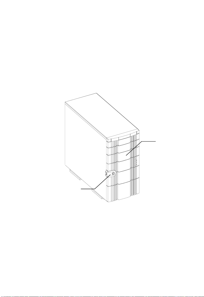
1.2.1 Front Panel
Panel Door
Keylock
Altos 1100E Series User’s Guide1-2
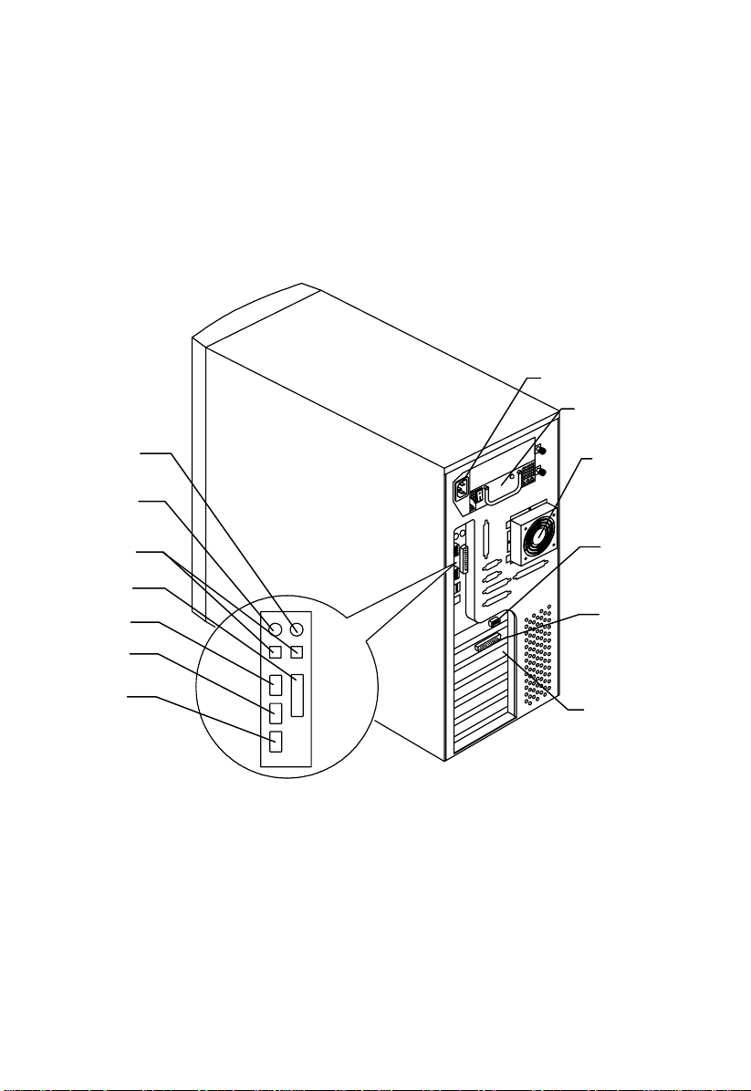
1.2.2 Rear Panel
Mouse Port
Keyboard Port
USB Ports
Power Socket
Hot-Swap Redundant
Power Supply
External Housing
Fan
AGP Video
Connector
Parallel Port
Com1
Com 2
RJ-45
External SCSI
Connector
Expansion Slots
Chapter 1 – System Housing 1-3
1.3 Internal Structure
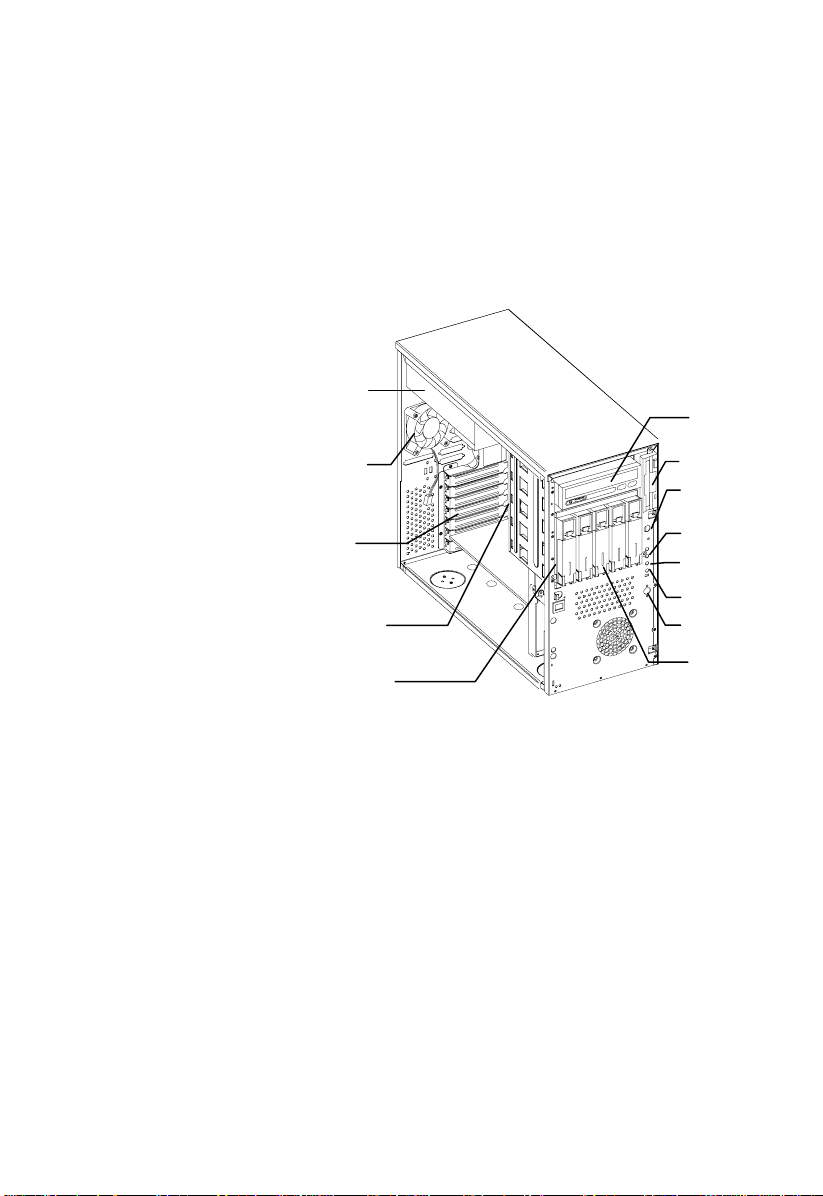
Hot-swap
Redundant
Power Supply
5.25-inch Drive Bays
Internal
Housing Fan
Expansion Card
Slots
Backplane Board
Hot-Swap Cage
(SCSI)
3.5-inch Drive Bay
Power Switch
System Status LED
Hard Disk Drive LED
RDM LED
Reset Switch
Removable Hard Disk
Drive Trays
Altos 1100E Series User’s Guide1-4
1.4 Opening the Housing Panels
1.4.1 Front Panel
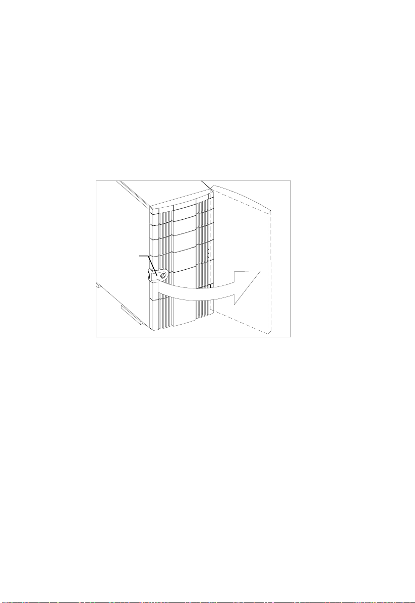
Key lock
To open the front panel, use the key to unlock and then pull the panel as shown in
the illustration above.
Chapter 1 – System Housing 1-5
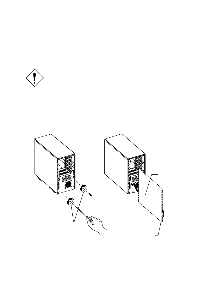
1.4.2 Left Panel
To remove the left panel:
Turn off the power switch and unplug the
power cord before removing the left panel.
See section 2.6 for important ESD
precautions and pre- and post-installation
instructions.
1. Remove the two front thumbscrews. Keep them in a safe place for later use.
2. Pull the panel handle out and use it to remove the left panel from the housing.
Left panel
screws
Left Panel Handle
Altos 1100E Series User’s Guide1-6
1.5 Installing Drives
Turn off the power switch and unplug the
power cord before installing or removing
drives. See section 2.6 for important ESD
precautions and pre- and post-installation
instructions.
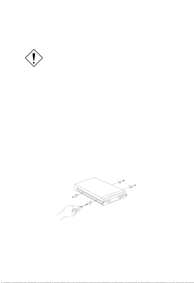
1.5.1 3.5-inch Drive
To install 3.5-inch drives:
1. Open the front panel of the housing. See section 1.4 for more information on
opening the housing panel.
2. Detach the 3.5-inch drive frame (2 pieces) from the housing by removing two
screws. Keep the screws for later use.
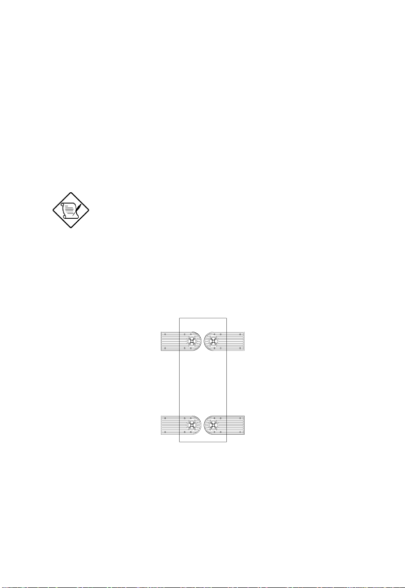
3. Attach the drive frames to the 3.5-inch drive securing it with four screws as
shown below.
Chapter 1 – System Housing 1-7
4. Insert the drive into the drive bay and secure it with two screws.
5. Connect the diskette drive cables and close the housing panels.
Altos 1100E Series User’s Guide1-8
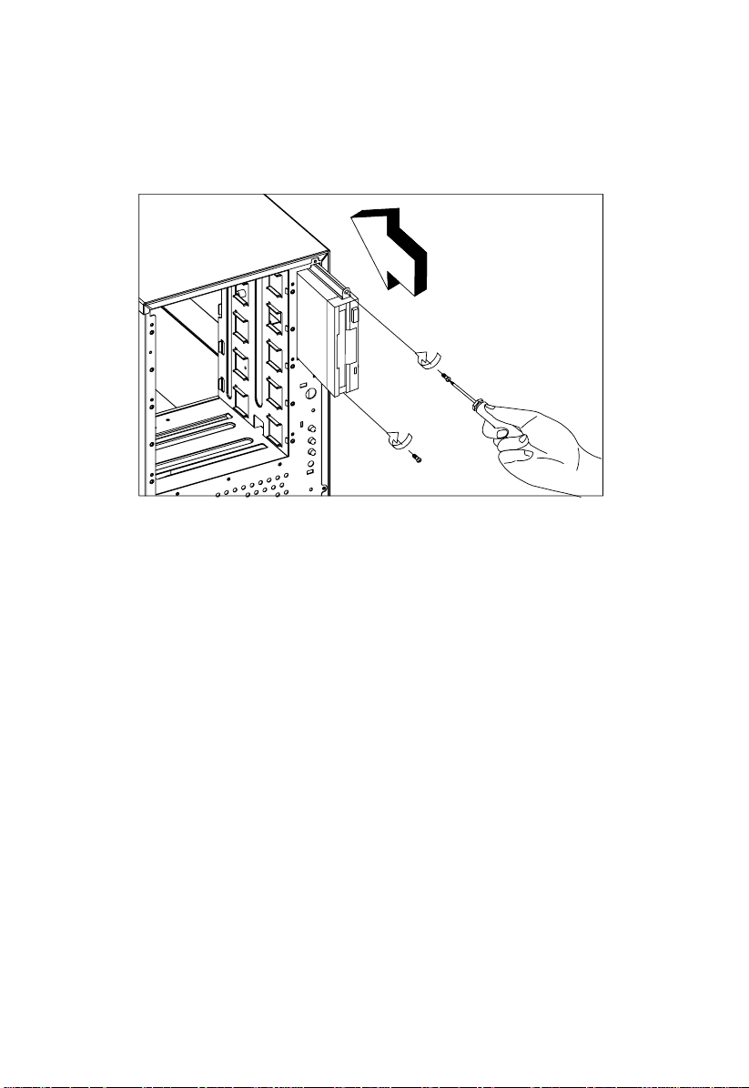
1.5.2 5.25-inch Drives
You may install a CD-ROM, digital audio tape (DAT), hard disk, diskette drive or
any other 5.25-inch device into the drive bay.
To install 5.25-inch devices:
1. Open the front panel. See section 1.4 for more information on opening the
housing panel.
2. Detach the 5.25-inch drive frame (2 pieces) from the housing by removing two
screws. Keep the screws for later use.
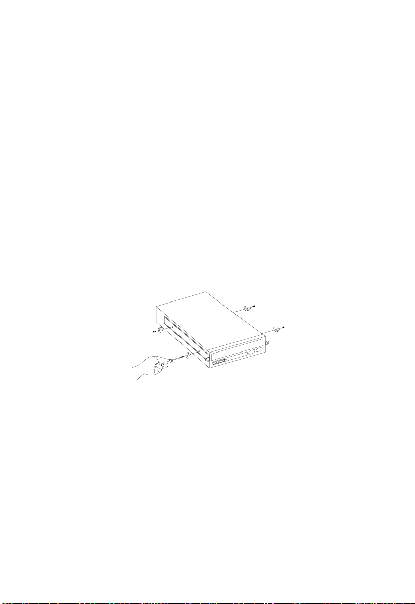
3. Attach the drive frames to the 5.25-inch drive securing it with four screws as
shown below.
Chapter 1 – System Housing 1-9
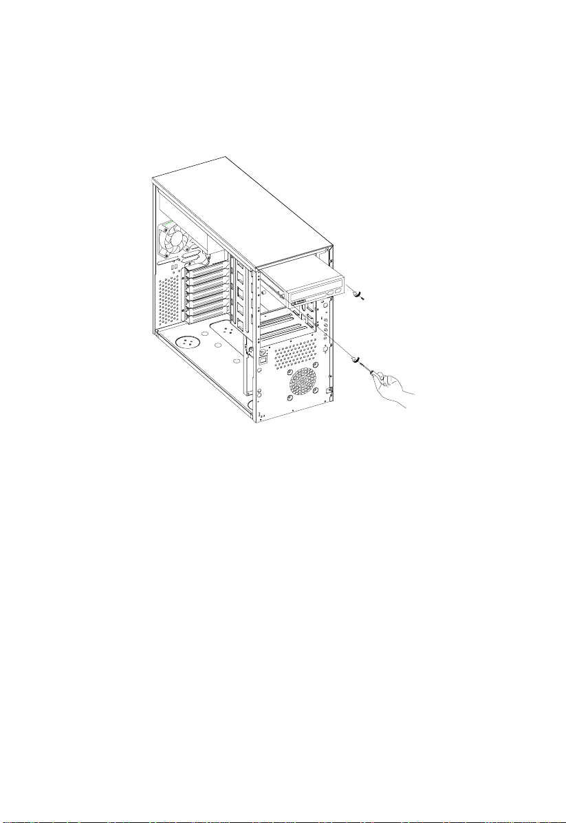
4. Insert the drive into the drive bay and secure it with two screws.
5. Connect the signal and power cables to the d r ive and close the housing panels.
Altos 1100E Series User’s Guide1-10
1.6 Installing Hot-Swap Cages
You can install either one BPL3 hot- swap cage or one B PL5 hot-swap c age into the
system housing. The system housing comes with one BPL5 hot-swap cage.
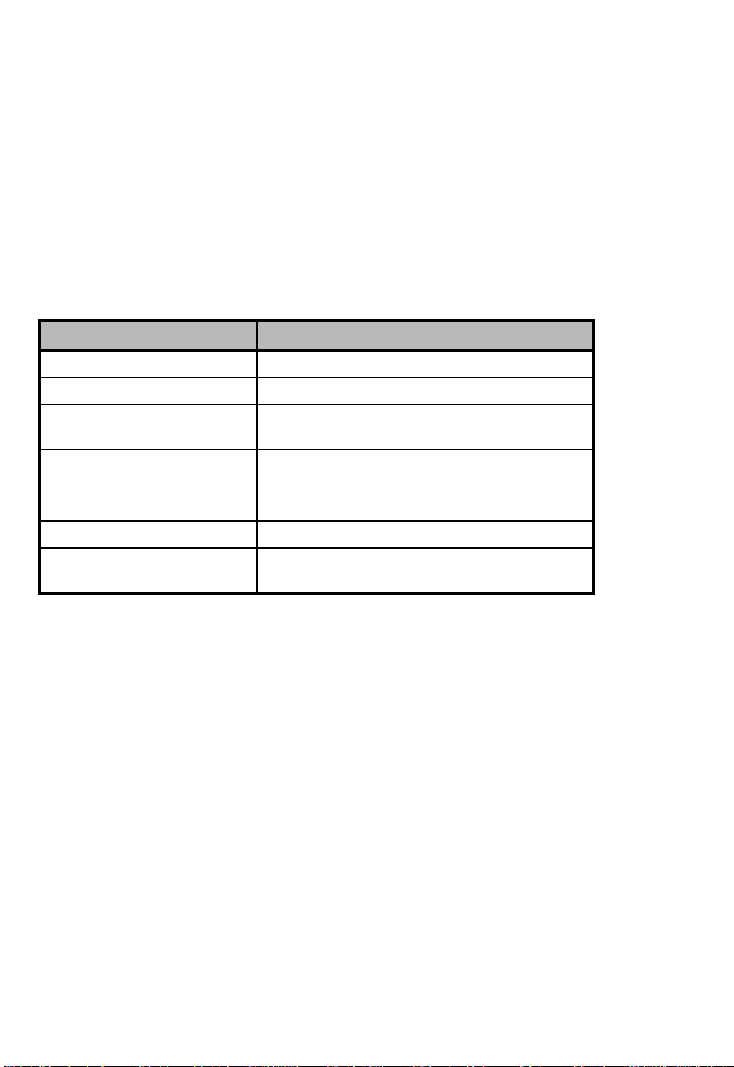
BPL3 and BPL5 Hot-Swap Cage Comparison Table
BPL3 BPL5
Dimension occupied Two 5.25” bays Three 5.25” bays
Cooling fans Two 6 cm fans One 12 cm fan
Power LED, HDD Access
LED, HDD Fail LED
HDD Support SCA HDD SCA HDD
Transfer Rate 80MB/s Ultra2
SCSI Termination Yes Yes
SCSI out (for termination
or expansion)
See section 1.10 for additional information about BPL3 and BPL5 backplane
boards.
Yes Yes
80MB/s Ultra2
LVD
Yes Yes
LVD
Chapter 1 – System Housing 1-11
Installing a BPL3 Hot-Swap Cage
To install the hot-swap cage into the housing:
1. Open the front panel and remove the left pa nel of the housing. Se e section 1.4
for more information on opening the housing panels.
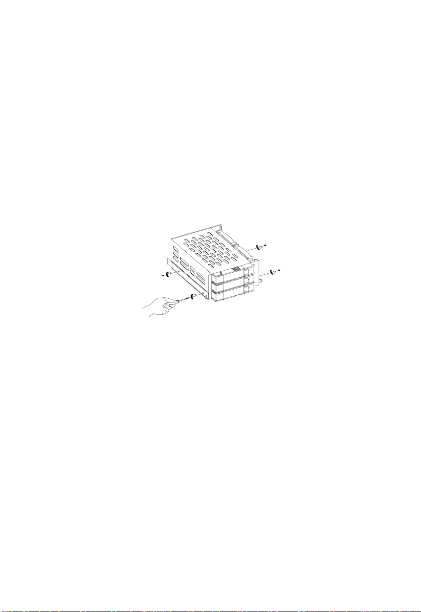
2. Attach the drive guides on the sides of the hot-swap cage with two screws on
each side. The drive guides come with the hot-swap cage.
Altos 1100E Series User’s Guide1-12
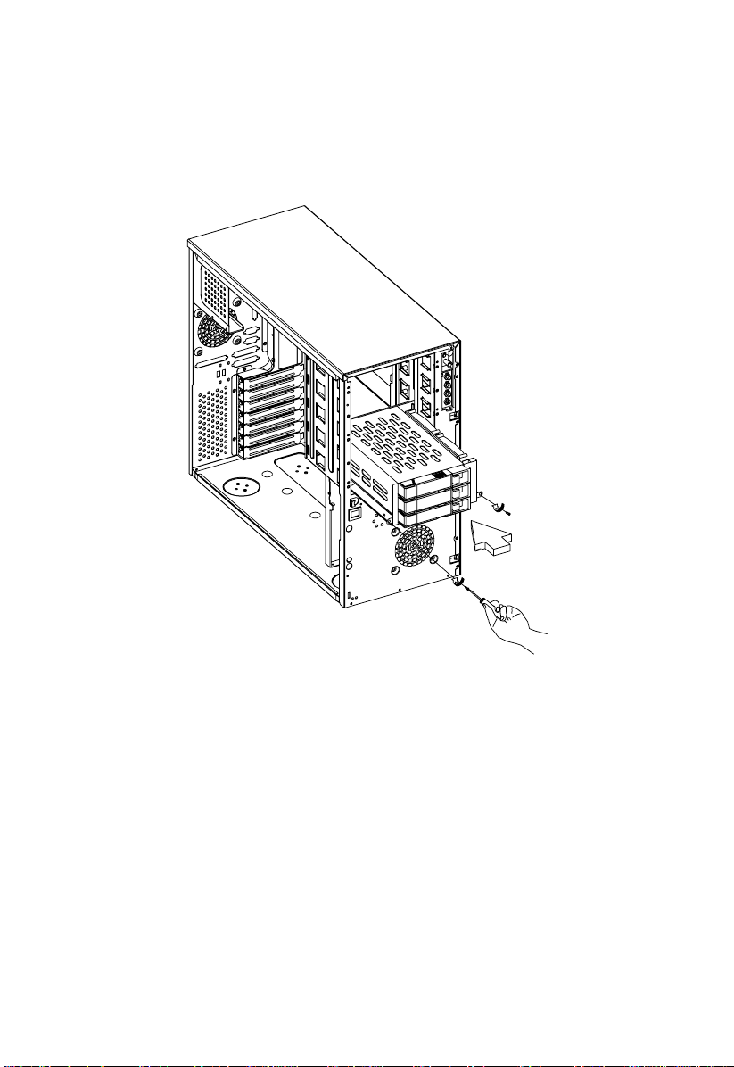
3. Insert the hot-swap cage into the housing and secure the hot-swap cage with
two screws as shown below.
Chapter 1 – System Housing 1-13
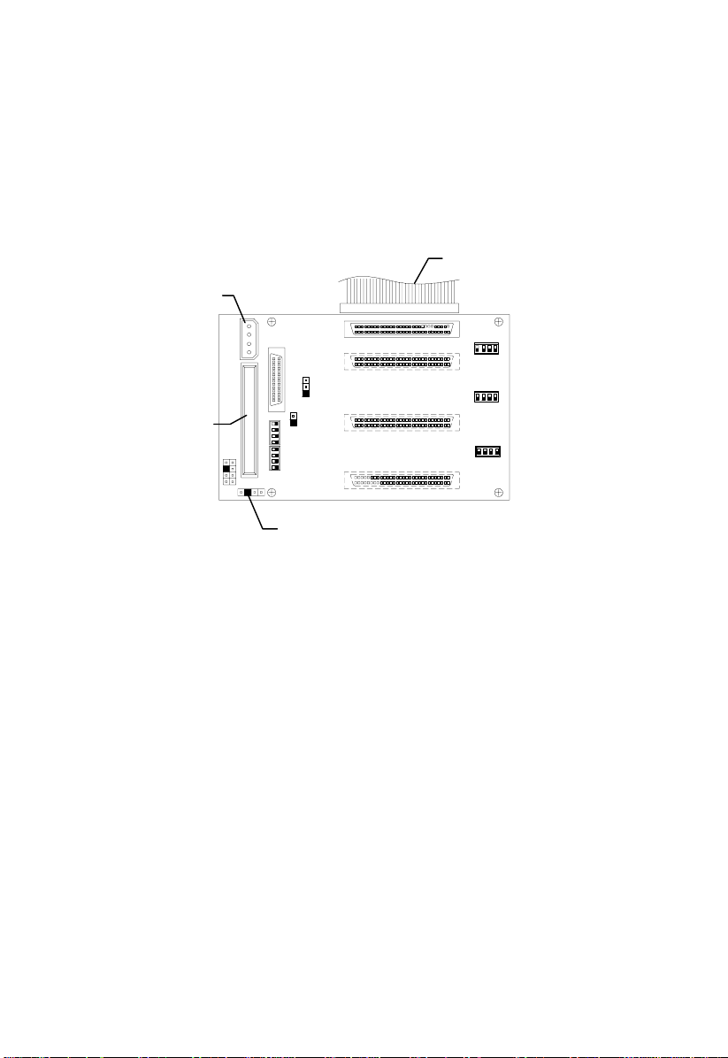
4. Attach the power cable, the SCSI terminator, the HDD fault LED cable, and the
system board connector cable to the backplane boa rd and attach the other end
of the connector cable to the system board. For the location of the SCSI
connector, please refer to Chapter 2, System Board.
System board
Power connector
SCSI
CN3: Connect to system
board’s HDD Fault LED
Altos 1100E Series User’s Guide1-14
 Loading...