

Acer AL711, AL716, AL712 Schematic

AM777/778/677/678 TFT LCD MONITOR CONTENTS
AM777/778/677/678 TFT LCD MONITOR CONTENTS................................................................................... 1
INTRODUCTION.......................................................................................................................................... 3
1.
1.1 Scope ....................................................................................................................................................................3
1.2 Description ........................................................................................................................................................... 3
2. ELECTRICAL REQUIREMENTS................................................................................................................. 4
2.1 Standard Test Conditions ..................................................................................................................................... 4
All tests shall be performed under the following conditions, unless otherwise specified. ............................................4
2.2 LCD monitor General specification ..................................................................................................................... 4
2.3 LCD Panel Specification ...................................................................................................................................... 5
2.4 Input Signals....................................................................................................................................................... 12
Supported Timing........................................................................................................................................................ 13
2.5 CONTROLS ........................................................................................................................................................ 16
2.6 White Color Temperature................................................................................................................................... 18
2.7 POWER SUPPLY ...............................................................................................................................................19
2.8 Plug & Play(EDID)............................................................................................................................................ 20
2.9 Audio Technical specification (AM777/677 Only) ............................................................................................. 20
3. VL-713 DISPLAY CONTROL BOARD...................................................................................................... 21
3.1 Description ......................................................................................................................................................... 21
3.2 Features.............................................................................................................................................................. 21
3.3 BLOCK DIAGRAM ............................................................................................................................................ 22
System Block Diagram................................................................................................................................................ 22
3.4 Connector Locations ..........................................................................................................................................22
3.5 Connector Type ..................................................................................................................................................23
3.6 Connector pin assignment .................................................................................................................................. 23
4. VK-713 Control Panel Board ................................................................................................................... 26
4.1 Description ......................................................................................................................................................... 26
4.2 Connector and Switch Locations........................................................................................................................ 26
4.3 Connector type.................................................................................................................................................... 26
4.4 Connector pin Assignment.................................................................................................................................. 26
4.5 Switch definition .................................................................................................................................................27
4.6 LED definition .................................................................................................................................................... 27
5. POWER SUPPLY & INVERTER BOARD ................................................................................................. 28
5.1 Description ......................................................................................................................................................... 28
5.2 Power supply ( AC to DC section)...................................................................................................................... 28
5.3 Inverter (DC to AC Section) ............................................................................................................................... 29
5.4 Electrical characteristics.................................................................................................................................... 29
5.5 Connector locations............................................................................................................................................ 30
5.6 Connector locations............................................................................................................................................ 32
6. TROUBLESHOOTING............................................................................................................................... 34
6.1 Main Procedure.................................................................................................................................................. 34
7. Power Line Transient Test (IEC 61000-4-4 Fast Transients/Burst)............................................................ 38
7.1 Peak Voltage: .....................................................................................................................................................38
7.2 Polarity : + / - ............................................................................................................................................. 38
7.3 Repetition Frequency of the impulse : 5 KHz..................................................................................................... 38
7.4 Rise-Time : 5ns ± 30% ..................................................................................................................................... 38
7.5 Impulse Duration: 50 nS ± 30%......................................................................................................................... 38
7.6 Relation to Power Supply: Asynchronous .......................................................................................................... 38
7.7 Burst Duration: 15 ms ± 20% ............................................................................................................................38
7.8 Burst Period: 300 ms ± 20% .............................................................................................................................. 38
7.9 Climatic Conditions: .......................................................................................................................................... 38
7.10 Test Procedure: ..................................................................................................................................................38
8. Power Line Surge Test (IEC 61000-4-5 Surge) ...................................................................................... 40
8.1 Climatic Condition .............................................................................................................................................40
8.2 Test Conditions:.................................................................................................................................................. 40
8.3 ............................................................................................................................................................................ 40
8.4 ............................................................................................................................................................................ 40
8.5 ............................................................................................................................................................................ 40
8.6 ............................................................................................................................................................................ 40
8.7 Display set high-resolution mode, AC input use AC 240V................................................................................. 40
1

9. ENVIROMENT REQUIREMENT................................................................................................................ 41
9.1 Operating............................................................................................................................................................ 41
9.2 Storage or Shipment ........................................................................................................................................... 41
10. REGULATION COMPLIANCE .................................................................................................................. 42
10.1 This product comply to the most current revisions of following regulations: ....................................................42
10.2 Electrostatics Discharge (ESD).......................................................................................................................... 43
11. QUALITY AND RELIABILITY.................................................................................................................... 44
11.1 Quality Assurance .............................................................................................................................................. 44
11.2 Reliability ........................................................................................................................................................... 44
Appendix A: PART LIST................................................................................................................................ 45
Appendix B: PCBA Assembly --------------------------------------------------------------------------------------------------53
Appendix C: DISPLAY UNIT ASSEMBLY -----------------------------------------------------------------------------------82
2
1. INTRODUCTION
1.1 Scope
This specification defines the requirements for the 17” MICRO-PROCESSOR based Multimode supported high resolution color LCD monitor, This monitor can be directly connected
to general 15 pin D-sub VGA connector and DVI-D digital connector, eliminates the
requirement of optional special display card. It also supports VESA DPMS power
management and plug & play function. There is a build-in stereo audio amplifier with
volume control to drive a pair of speakers.
1.2 Description
The LCD monitor is designed with the latest LCD technology to provide a performance
oriented product with no radiation. This will alleviate the growing health concerns. It is also
a space saving design, allowing more desktop space, and comparing to the traditional CRT
monitor, it consumes less power and gets less weight in addition MTBF target is 20k
hours or more.
Comparison Chart of AM777 (AL712)/778/677(AL716)/678(AL711)
AM778 AM777 (AL712)
Panel Normal 17” panel
AU M170EN05
Hydis HT17E12-200
Normal 17” panel
AU M170EN05
Hydis HT17E12-200
Signal Interface DSUB+DVI-D DSUB+DVI-D
Sync Type for analog input
Color Temp user adjust
DDC
Speaker No 1W+1W
Headphone Jack No Yes
Microphone Jack No No
USB Hub Not support Not support
Tilt / Swivel Yes / No Yes / No
Height Adjust Option
Separate / compatible / Separate / compatible /
Support
DDC2B DDC2B
Support
Option
AM678 (AL711) AM677 (AL716)
Panel Normal 17” panel
AU M170EN05
Samsung LTM170EU-L02
Signal Interface DSUB DSUB
Sync Type for analog input
Color Temp user adjust
DDC
Speaker No 1W+1W
Headphone Jack No Yes
Microphone Jack No No
USB Hub Not support Not support
Tilt / Swivel Yes / No Yes / No
Height Adjust Option
Separate / compatible / Separate / compatible /
Support
DDC2B DDC2B
Normal 17” panel
AU M170EN05
Samsung LTM170EU-L02
Support
Option
3

2. ELECTRICAL REQUIREMENTS
2.1 Standard Test Conditions
All tests shall be performed under the following conditions, unless otherwise specified.
Ambient light
Viewing distance
Warrn up time
All specifications: 30 minutes
Fully functional: 5 seconds
Measuring Equipment
Connected to the monitor under test.
Minolta CA100 photometer, or equivalent
Control settings
User brightness control: Maximum (unless otherwise specified )
User contrast control: Typical (unless otherwise specified )
User red/white balance,
Green/white balance and
Blue/white balance control: In the center (unless otherwise specified )
Power input
Ambient temperature
Analog input mode
: 225 lux
: 50 cm in front of LCD panel
: Chroma 2250 signal generator or equivalent, directly
: 110Vac or 230Vac
: 20 ± 5 ˚C ( 68 ± 9 ˚ F)
: 1280 x1024 /60 Hz
2.1.1 MEASUREMENT SYSTEMS
The units of measure stated in this document are listed below:
1 gamma = 1 nano tesla
1 tesla = 10,000 gauss
cm = in x 2.54
lb = kg x 2.2
degrees F = [°C x 1.8] + 32
degrees C = [°F - 32]/1.8
u' = 4x/(-2x + 12y + 3)
v' = 9y/(-2x + 12y + 3)
x = (27u'/4)/[(9u'/2) - 12v' + 9]
y = (3v')/[(9u'/2) - 12v' + 9]
nits = cd/(m2) = Ft-L x 3.426
lux = foot-candle x 10.76
2.2 LCD monitor General specification
Panel Type : 17 “ active matrix color TFT LCD
1). Hydis LT17E12-200
Display size : 337.92mm(H) x 270.34mm(V)
Display mode : VGA 720 X 400 (70 Hz)
VGA 640 X 480 (60/66/70/72/75 Hz)
SVGA 800 X 600 (60/70/72/75 Hz)
XGA 1024 X 768 (60/70/75 Hz)
4

SXGA 1280 X 1024 (60/70/75 Hz) standard resolution
Pixel pitch : 0.098x3mm(H) x 0.294mm(V)
Display Dot : 1280 x (RGB) x 1024
Pixel Clock : 25.2 – 135.0MHz
Contrast ratio:
Brightness: 250 cd/m
Response time (Tr/Tf) : 20 /20 msec
Display color : 16777216 (8 bite color)
Viewing angle: L / R ≧ 80 / ≧ 80 ( ≧ 160 degrees horizontal typical)
U / D ≧ 65 / ≧ 65 ( ≧ 130 degrees vertical typical)
Luminance Uniformity : > 80 %
Pc interface: 1). Video : RGB analog 0.7V peak to peak
Sync : TTL positive or negative
2). Digital TMDS
Signal connector : 15 pin Mini D type, (standard VGA video)
DVI-D connector
3.5 mm stereo audio jack(Audio)(AM777/677)
3.5 mm miniature stereo Headphone jack(AM777/677)
θ
= 0˚ 430 : 1 (typical)
2
(typical)
Audio power : 1Wrms + 1Wrms ( 300Hz – 10kHz (S.P.L. – 10 dB))
(AM777/677)
Front control : power on/off with LED select (up, down) adjustment (+,-)
Interface frequency
y Horizontal Frequency 24KHz --80KHz(analog), 31.5– 80KHz(digital)
y Vertical Frequency 56Hz ----75Hz
Plug & play : Support VESA DDC2B functions
Power Input voltage : Single phase, 50/60HZ, 100VAC to 240VAC ±10%
Total output power : 48 Watt max.
2.3 LCD Panel Specification
2.3.1 LCD Panel Model (Hydis LT17E12-200)
• Display Type active matrix color TFT LCD
• Resolution 1280 x 1024 pixels
• Display Dot 1280 x (RGB) x1024
• Display Area 337.92mm(H) x 270.23mm(V)
5
• Pixel Pitch 0.264mm(H) x 0.264mm(V)
• Display Color 16M (6bite color+FRC)
• Lamp Voltage 700Vrms (typ)
• Lamp Current 6.5mArms (typ)
• Weight 1900g (typ)
• Optical Specifications
IL = 6.5mA (RMS) Ta = 25 ± 2°C VDD = 5V FV = 60HZ F
ITEM Symbol Condition MIN. TYP. MAX. UNIT
Contrast Ratio
(Center of screen)
Rising TR Response
Time at Ta
Luminance of white
(Center of screen)
Color
Chromaticity
(CIE)
Viewing
Angle
Brightness Uniformity B
Flicker F - - 5 %
Cross talk CT - - 2.0 %
Falling T
Red
Green
Blue
White
Hori.
Vert.
CR 350 430 _
F
Y
200 250 30 cd/m2
L
RX 0.599 0.629 0.659
R
0.324
Y
GX 0.257 0.287 0.317
GY 0.568 0.598 0.628
BX 0.115 0.145 0.175
BY 0.073 0.103 0.133
WX 0.270 0.300 0.330
W
Y
θL
θR
φH
φ
L
- - 1.2
UNI
φ=0,
θ=0
Normal
Viewing
Angle
CR≥10
- 20 -
0
354
0.305 0.335 0.365
- 80 -
- 80 -
- 65 -
- 65 -
= 54MHZ
DCLK
(total)
msec
0.384
Degrees
2.3.2 LCD Panel Model (AU M170EN05)
• Display Type active matrix color TFT LCD
• Resolution 1280 x 1024 pixels
• Display Dot 1280 x (RGB) x 1024
• Display Area 337.92mm(H) x 270.34mm(V)
• Pixel Pitch 0.264mm(H) x 0.264mm(V)
• Display Color 262K (6 bit color)
• Lamp Voltage 700 Vrms typ.
• Lamp Current 7mA rms.( typ). 4 Lamp
• Weight 2000g .
• Optical Specifications
6
The following items are measured under stable conditions. The optical characteristics
should be measured in a dark room or equivalent state with the methods shown in
Note(4).
Measuring equipment : TOPCON BM-5A, BM-7, PHOTO RESEARCH PR650
(Inverter Freq. : 54kHz) *Ta =25 ± 2°C, VDD=5V, fv=60 Hz, fDCLK=54 MHz, IL= 6.5mArms
Item
Contrast Ratio
(Center of screen)
Response
Time
Luminance of White
(Center of screen)
Color
Chromaticity
(CIE 1931)
Viewing
Angle
Brightness Uniformity
(9 points)
Symbol
CR
Rising TR - 12 20
Falling T
Red
Green
Blue
White
Hor.
Ver.
F - 4.0 5
L
Y
Rx 0.64
Ry 0.34
Gx 0.29
Gy 0.61
Bx 0.14
By 0.07
Wx 0.31
Wy
θ
L
θ
R
φ
H
φ
L
B
UNI
Condition Min. Typ. Max.
250 400 -
Normal
φ
= 0˚
θ
= 0˚
Viewing
Angle
CR≥5
75 - -
200 260 -
TYP.
-0.03
0.33
70 80 -
70 80 -
70 80 -
70 80 -
TYP.
+0.03
Unit
msec
cd/m2
Degrees
%
Note
(1)(2)(4)
BM-5A
(1)(3)
BM-7
(5)
BM-5A
(1)(4)
PR650
(1)(4)
BM-5A
(6)
BM-5A
Note 1) Definition of Viewing Angle: Viewing angle range (10≤CR)
Note 2) Definition of Contrast Ratio (CR): Ratio of gray max(Gmax),gray min(Gmin) at the
center point of panel.
7
Luminance with all pixels white (Gmax)
CR=
Luminance with all pixels black (Gmin)
Note 3) Definition of Response time: Sum of T
, TF
R
8
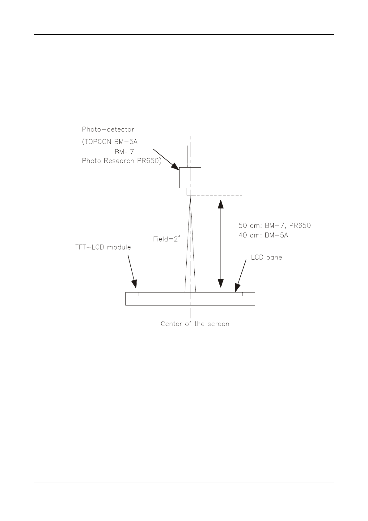
Note 4) After stabilizing and leaving the panel alone at a given temperature for 30 min, the
measurement should be executed .Measurement should be executed n a stable,
windless ,and dark room.30 min after lighting the back-light. This should be
measured in the center of screen. Dual lamp current :13.0mA(6.5mA x2)(Refer to
the note(1) in the page 14 for more information ).
Environment condition :Ta=25±2°C
Optical characteristics measurement setup
9
Notes 5) Definition of Luminance of White : measure the luminance of white at center point.
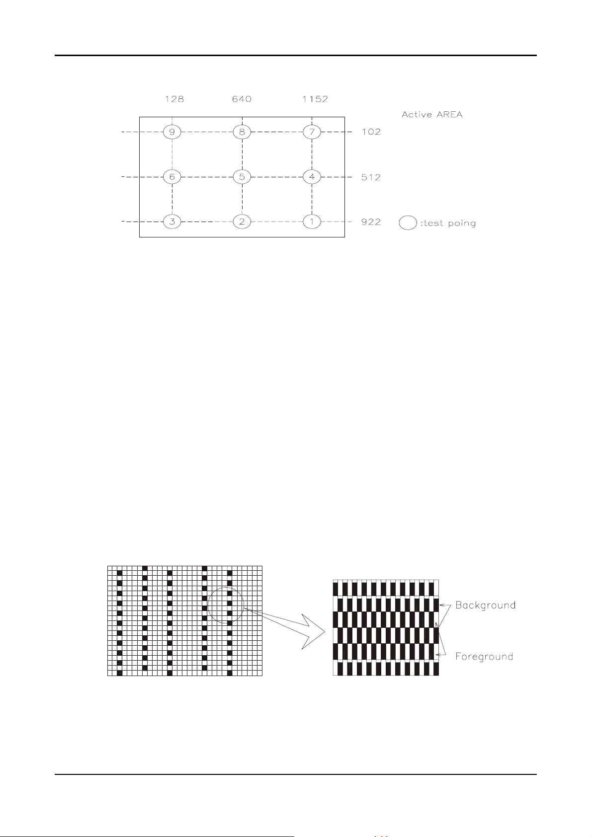
Notes 6)Definition of 9 points brightness uniformity (Measuring points: Refer to the Note 5)
Bmin
B
=100∗
UNI
Bmax
Bmax: Maximum brightness
Bmin: Minimum brightness
Notes 7) Definition of Flicker level
Flicker Voltage
pp
F = x 100 %
LMD Voltage
dc
♦ One maximum value of three estimated values.
♦ For this test ,an LMD(Light Measurement Device)is needed with adequate response time
to track any visible rate flicker component and with a voltage level output proportional
To luminance intensity.
♦ Test Pattern: For dot inversion Driving(Gray levels of foreground dots on the test panel
Are G22,G32,and G45)
♦ Test Point :Center point of the display area
10
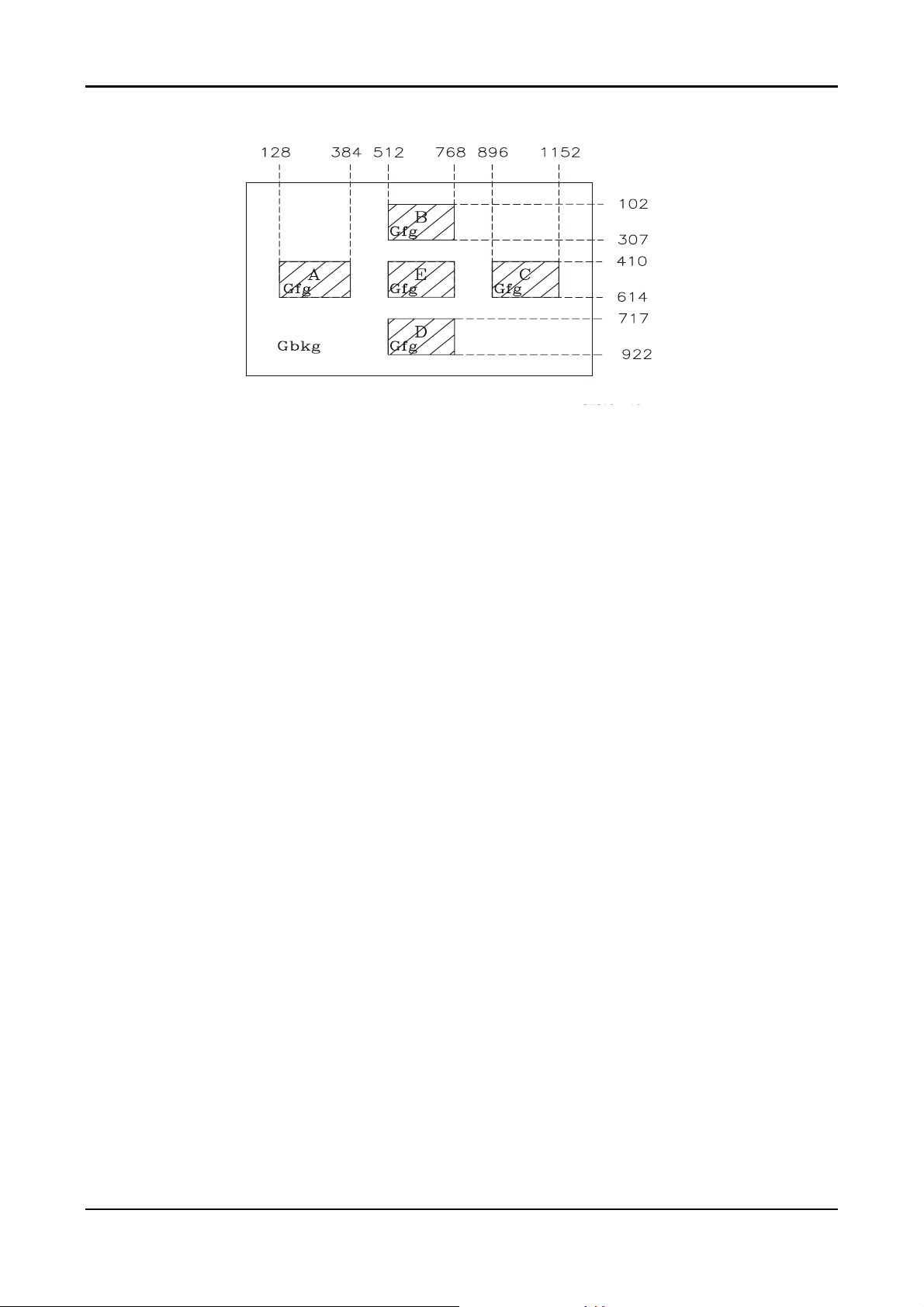
Note 8) Definition of Crosstalk (Refer to the VESA STD)
The calculation for shadowing is made from the 2 luminance measurements Gbkg and Lsh,
as follows:
Lmax -Lmin
C
= x100 %
T
Lmin
Where Lmax is the larger value of Gbkg or Lsh , and Lmin is the smaller of the two.
♦ To determine background and foreground levels (colors),first set the background to any
gray scale or color level suitable for shadowing determination.(Note that it may take
several iterations of adjusting background level and box levels to determine the proper
value for the background .Next display the box levels to determine the proper value for the
background level. Look for shadowing in any direction from box E. Independently vary the
gray level (or color) of the background and box E until the worst case shadowing is
observed. This defines the background (Gbkg) and foreground (Gfg) levels to be
maintained for the remainder of the test.
♦ One point only (the target) will be measured. To determine that point proceed as follows
Using the background and foreground gray levels of step1 (Gbkg and Gfg). Turn on each
box at a time. Look for the case with the worst shadowing. The box causing the worst case
is the shadowing source, or Bsrc. Use Bsrc and the box opposite from it that lies directly in
the shadow path. That is the target box, or Btgt. Note that box Eight be either Bsrc or Btgt,
depending on the shadowing conditions, but typically Bsrc and Btgt will be a pair of
opposite boxes, A&C or B&D. Btgt will only be displayed for aligning the LMD. It will be
turned off for the actual measurement.
♦ The target box point (Btgt) will be measured with the source box (Bsrc) turned on then off.
(Btgt is for alignment purpose only) Display the background only at level Gbkg. Display
Btgt determined in step 2 above. Using the correct distance, angle, and measurement
aperture, align the LMD to the center of the Btgt. Turn off Btgt. With Gbkg set to its proper
level, measure the luminance (or color). Next,turn on the source box Bsrc. Again measure
at the center point of Btgt (without Btgt present.). In this case the LMD will be measuring
the shadowing level, Lsh.
11
2.4 Input Signals
2.4.1
2.4.2
2.4.3
Video input
• Type Analog R, G, B., Digital TMDS
• Input Impedance 75 ohm +/- 2%
• Polarity Positive
• Amplitude 0 - 0.7 +/- 0.05 Vp
• Display Color same as LCD panel
Sync input
• Signal separate horizontal and vertical sync, or composite sync
which are TTL compatible
• Polarity positive and negative.
Interface frequency
The following frequency range is generalized by supported timing. If the entered
mode does not match the supported timing the display optimization will not be
assured.
• Horizontal Frequency 24KHz --80KHz(analog), 31.5– 80KHz(digital)
• Vertical Frequency 56Hz ---------75Hz
DISPLAY MODES
MONITOR
MODE NO.
1 640x350 31.5 + 70.0 - 25.0 VGA
2 640X400 24.83 - 56.4 - 21.05 NEC
3 640X400 31.5- 70.0+ 25.0 VGA
4 640X400 31.5- 70.1- 25.19 NEC
5 640X480 31.5 - 60.0 - 25.0 Defacto
6 640X480 35.0- 66.67- 30.24 MAC
7 640X480 37.86- 72.80- 31.5 VESA
8 640X480 37.5- 75.0- 31.5 VESA
9 720X400 31.5 - 70.0 + 28.0 Text Defacto
10 832X624 49.72- 74.55 - 57.28 MAC
11 800X600 35.16+ 56.25+ 36.0 SVGA
12 800X600 37.8 + 60.0 + 40.0 VESA
13 800X600 48.07 + 72.18 + 50.0 VESA
14 800X600 46.87+ 75.0+ 49.5 VESA
15 1024X768 48.4 - 60.0 - 65.0 VESA
16 1024X768 53.96 + 66.13 + 71.66 XGA
17 1024X768 56.47 - 70.07 - 75.0 VESA
18 1024X768 60.0 + 75.0 + 78.75 VESA
19 1024x768 60.24- 75.02- 80.0 MAC-768
20 1280X1024 64.0 + 60.0 + 108.5 SXGA
21 1280X1024 80.0 + 75.0 + 135.0 Defacto
SCREEN
RESOLUTION
HORIZONTAL
SYNC RATE
(kHz)
VERTICAL
SYNC RATE
(Hz)
VIDEO CLK
(MHz)
STANDARD
12
Supported Timing
TIMING
FV(HZ) POLARITY (DOT/LINE) (DOT/LINE) WIDTH PORCH PORCH FOREQ.(MHZ)
(DOT/LINE) (DOT/LINE) (DOT/LINE)
640x350 31.469 + 800 640 96 16 48 25.175
VGA-350 70.087 – 449 350 2 37 60
640x400 24.83 – 848 640 64 64 80 21.05
NEC PC9801 56.42 – 440 400 8 7 25
640x400 31.469 – 800 640 96 16 48 25.175
VGA-GRAPH 70.087 + 449 400 2 12 35
640x400 31.5 – 800 640 64 16 80 25.197
NEC PC9821 70.15 – 449 400 2 13 34
640x480 31.469 – 800 640 96 16 48 25.175
VGA-480 59.94 – 525 480 2 10 33
640x480 35.00 – 864 640 64 64 96 30.24
APPLE MAC480
640x480 37.861 – 832 640 40 16 120 31.5
VESA-480-72Hz 72.809 – 520 480 3 1 20
640x480 37.5 – 840 640 64 16 120 31.5
VESA-480-75Hz 75 – 500 480 3 1 16
720x400 31.469 – 900 720 108 18 54 28.322
VGA-400-TEXT 70.087 + 449 400 2 12 35
832x624 49.725 – 1152 832 64 32 224 57.2832
APPLE MAC800
800x600 35.156 + 1024 800 72 24 128 36
SVGA 56.25 + 625 600 2 1 22
800x600 37.879 + 1056 800 128 40 88 40
VESA-600-60Hz 60.317 + 628 600 4 1 23
800x600 48.077 + 1040 800 120 56 64 50
VESA-600-72Hz 72.188 + 666 600 6 37 23
800x600 46.875 + 1056 800 80 16 160 49.5
VESA-600-75Hz 75 + 625 600 3 1 21
1024x768 48.363 – 1344 1024 136 24 160 65
XGA 60.004 – 806 768 6 3 29
1024x768 53.964 + 1328 1024 176 16 112 71.664
COMPAQ-XGA 66.132 + 816 768 4 8 36
1024x768 56.476 – 1328 1024 136 24 144 75
VESA-768-70Hz 70.069 – 806 768 6 3 29
1024x768 60.023 + 1312 1024 96 16 176 78.75
VESA-768-75Hz 75.029 + 800 768 3 1 28
1024x768 60.24 – 1328 1024 96 32 176 80
APPLE MAC768
1280x1024 64 + 1688 1280 112 48 248 108
VESA-102460Hz
1280x1024 80 + 1688 1280 144 16 248 135
VESA-102475Hz
If the input timing is not a supported timing listed above but within the supported frequency
range (Horizontal: 80KHz,Vertical: 75Hz), this monitor will select a closest mode instead. But
the display quality may not be optimized.
If the input timing over the supported frequency range, a message “Input Signal Out of Range”
will be shown.
FH(KHZ) SYNC TOTAL ACTIVE SYNC FRONT BACK PIXEL
66.67 – 525 480 3 3 39
74.55 – 667 624 3 1 39
75.02 – 803 768 3 3 29
60 + 1066 1024 3 1 38
75 + 1066 1024 3 1 38
13
2.4.4
85Hz refresh rate Support
Monitor should display 85Hz refresh rate mode as emergency mode.
Monitor should display “Out of Range” warning menu at this mode.
2.4.5
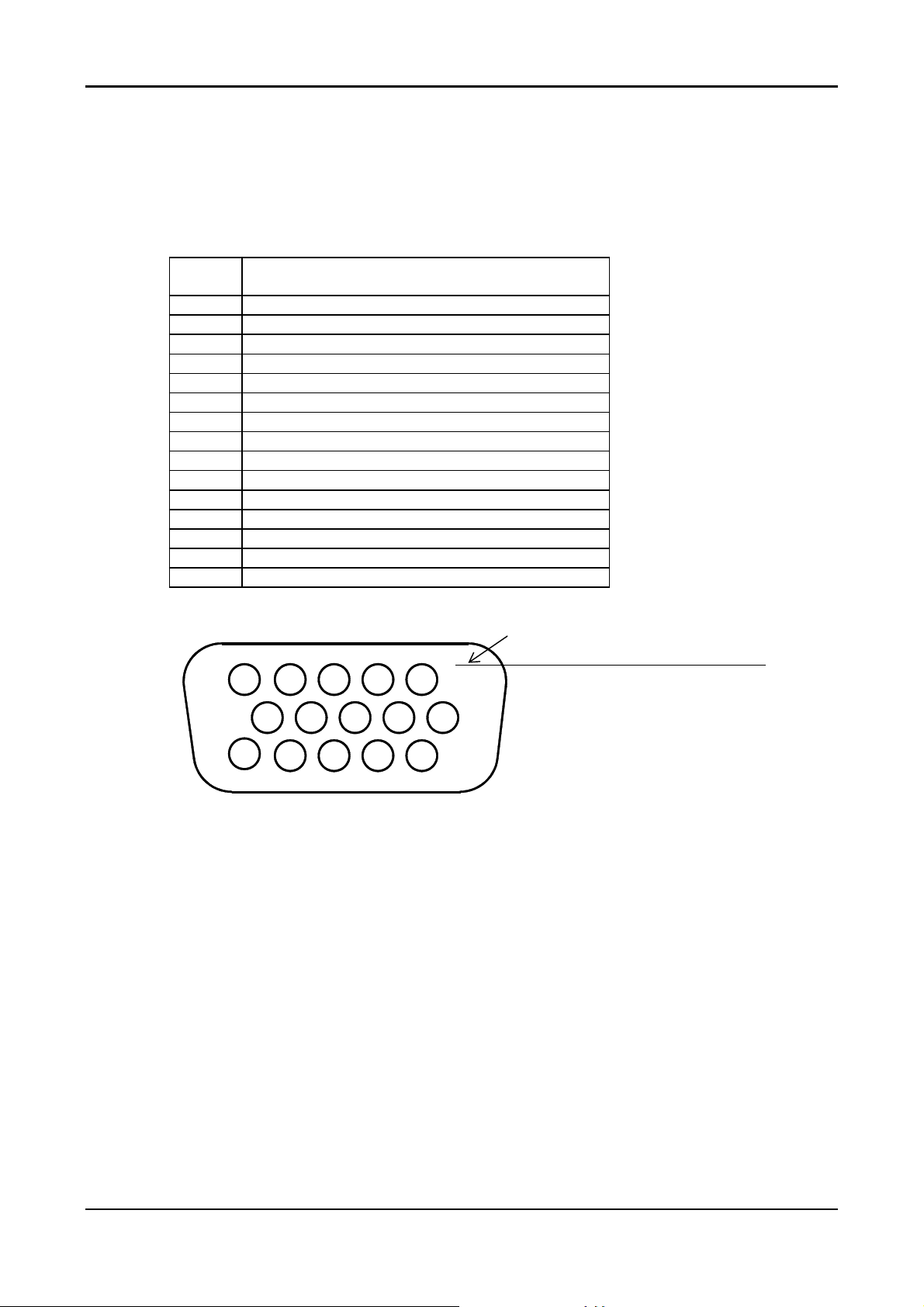
Video input Connector
Analog Video input Connector: 15pins mini D-Sub
Table 2.4.5. Pin assignment for D-sub connector
PIN
NO.
1 RED VIDEO
2 GREEN VIDEO
3 BLUE VIDEO
4 GROUND
5 GROUND
6 RED GROUND
7 GREEN GROUND
8 BLUE GROUND
9 PC5V (+5V DDC)
10 CABLE DETECTION
11 GROUND
12 SDA
13 H.SYNC
14 V.SYNC
15 SCL
Separate Sync
Color of plastic parts: Blue (PC99)
5
10
15
D-sub connector
1
6
11
14
 Loading...