

Page 1

AL2103W (Acer)
L22HCTN-URC(VGA + DVI)
21.6” wide Color TFT LCD Display
Page 2

Copyright
Copyright © 2008 by Acer Corporation. All rights reserved. No part of this publication may be
reproduced, transmitted, transcribed, stored in a retrieval system, or translated into any
language or computer language, in any form or by any means, electronic, mechanical,
magnetic, optical, chemical, manual or otherwise, without the prior written permission of
Acer Corporation.
Disclaimer
Acer makes no representations or warranties, either expressed or implied, with respect to the
contents hereof and specifically disclaims any warranty of merchantability or fitness for any
particular purpose. Further, Acer reserves the right to revise this publication and to make
changes from time to time in the contents hereof without obligation of Acer to notify any
person of such revision or changes.
Trademarks
Acer is a registered trademark of Acer Corporation.
All other trademarks used within this document are the property of their respective owners.
Product disposal at end of product life
The lamp in this product contains mercury. Please dispose of in accordance with local, state
or federal laws.
2
Page 3

Revision History
Revision SM Editing Date ECR Number Description of Changes Editor
3
Page 4

TABLE OF CONTENTS
1. Precautions and Safety Notices ..........................................................................05
2. Specification ..........................................................................................................06
3. Front Panel Function Control Description ..........................................................09
4. Circuit Description................................................................................................12
5. Adjusting Procedure.............................................................................................15
6. Trouble Shooting Flow Chart ..............................................................................37
7. Block Diagrams .................................................................................................... 39
8. Schematic Diagrams .............................................................................................41
9. PCB Layout Diagrams ......................................................................................... 45
10. PCB Main Board & PI Board List....................................................................... 47
4
Page 5

1. Precautions and Safety Notices
1.1 Safety Precautions
Although LCD monitors are displays without high voltage as that in the CRT monitors, the
following precautions still should be taken care of.
1 Observe all cautions and safety related notes located inside the display cabinet and on
the display chassis.
2 Operation of these displays outside the cabinet or with the cover removed involves a
shock hazard from the display backlight’s inverter. Work on the display should not be
attempted by anyone who is not thoroughly familiar with precautions necessary when working
on high voltage equipment.
3 Before returning a serviced display to the customer, a thorough safety test must be
performed to verify that the display is safe to operate without danger or shock.
1.2 Product Safety Notice
1 Many electrical and mechanical parts in this chassis provide special visual safety
protection. The protection afforded by them cannot necessarily be obtained by using
replacement components rated for higher voltage, wattage, etc.
2 Before replacing any of these components, read the parts list included in this manual
carefully. The use of substitute replacement parts, which do not have the same safety
characteristics, as specified in the parts list may create shock, fire or other hazards, and
hence should be prohibited.
1.3 Service Notes
1 When replacing parts or circuit boards, wrap the wires around terminals before soldering.
2 Keep wires away from high temperature components.
3 Keep cable and their shielding in their original position so as to reduce interference.
Abbreviations and Acronym
DDC Display Data Channel
DPMS Display Power Management System
EPA Environment Protection Agency
ESD Electrostatic Discharge
I2C-Bus Inter-IC Bus1
LCD Liquid Crystal Display
LED Light Emit Diode
TTL Transistor-Transistor Logic
VESA Video Electronics Standards Association
5
Page 6

2. Specification
AC Power Input Output 90Vac ~ 264Vac Full Range, 50/60 Hz.
<1.5A@110V; <0.8A@230V
Power Consumption LED color is Green: < 49 W
LED color is Amber: < 2 W
LED color is Dark: <1 W
Signal Input
Video Signals
Sync Signals
Input Frequency
Connector
Resolution (Max.)
Recommended mode
Pixel dot clock
Environment
Operating Conditions
RGB Analog (75 ohms, 0.7 / 1.0 Vp-p),
DVI (TMDS, 100 ohms)
Separate Sync / Composite Sync / SOG
Fh = 24 – 82 kHz ; Fv = 50 – 75 Hz
VGA 15-pin Mini D type (detachable cable)
DVI-D (support HDCP / DDC/CI)
Internal Power Adapter, 3-pin plug (CEE22)
1680 x 1050 / 60 Hz
1680 x 1050 / 60 Hz
160 MHz (maximum)
Temperature
Non Operating Condition
Temperature
Operating Relative Humidity
Non operating Relative Humidity
Operating Altitude
Non Operating Altitude
Pedestal Tilt
Forward
Backward
Panel Characteristics
Panel Type
Pixel Format
Pixel Pitch
Pixel Configuration
Display Mode
Display Area
5℃ to 35℃
-20℃ to 60℃
20% to 85%.
5% to 95%.
0 to 6,561.68 feet (2000m) .
0 to 40,000 feet (12192m).
5º
20º
CLAA220WA01 (CPT)
1680 (H) x 1050 (V) (1 pixel = R+G+B dot)
0.27675 mm (H) x 0.27675 mm (V)
R、G、B vertical stripe
Normally white, TN
464.94 (H) × 290.5875 (V) (21.6-inch diagonal)
6
Page 7

Faceplate Coating
Hard coating (3H), AG (Haze 25%)
Response Time
Luminance
Contrast Ration
Display Color
Backlight Unit
5ms
300 cd/m² (typical)
1000:1 (typical)
16.7M( 6bits+Hi-FRC)
CCFL, 4 tubes(top × 2/bottom × 2) , Edge light
Viewing Angle(H/V) H: 170 º / V:160 º
Plug and Play DDC/2B and DDC/CI
Power Management Complies with EPA and DPMS
Dimension (W x H x D) W :509.76 mm (20.1 inch)
H : 431.55mm (17 inch)
D : 225mm (8.9 inch)
Monitor Weight
4.5±0.2 Kg(9.90 lbs)
7
Page 8
2.1 Model Configuration Table
# Model Panel CPT Scalar IC Scalar board Power board Key
AL2203WQ b
1
(VGA)
AL2203WQ bm
2
(VGA / Audio)
AL2203WQ bd
3
(VGA / DVI)
AL2203WQ bmd
4
(VGA / DVI / Audio)
AL2103W
5
(VGA)
CLAA220WA01
Warehouse code
:032/073
CLAA220WA01
Warehouse code
:032/073
CLAA220WA01
Warehouse code
:032/073
CLAA220WA01
Warehouse code
:032/073
CLAA220WA01
Warehouse code
:032/073
M-Star
TSUMU18B
WJ-LF
M-Star
TSUMU18B
WJ-LF
M-Star
TSUMU58B
WHJ-LF
M-Star
TSUMU58B
WHJ-LF
M-Star
TSUMU18B
WJ-LF
PWB-1195
PWB-1195
PWB-1195
PWB-1195
PWB-1195
PWB-1207
PWB-1220
PWB-1220
PWB-1207
PWB-1220
PWB-1207
PWB-1220
PWB-1207
PWB-1220
PWB-1207
AL2103W
6
(VGA / DVI)
CLAA220WA01
Warehouse code
:032/073
M-Star
TSUMU58B
WHJ-LF
PWB-1195
PWB-1207
PWB-1220
# Model VGA Cables DVI Cable AUDIO Cable
AL2203WQ b
1
(VGA)
AL2203WQ bm
2
(VGA / Audio)
AL2203WQ bd
3
(VGA / DVI)
AL2203WQ bmd
4
(VGA / DVI / Audio)
AL2103W
5
(VGA)
Wire Ass'y VGA Signal Cable
20276(3+6) L=1800mm
D-SUB Core:14.2*28.5*6.35
Wire Ass'y VGA Signal Cable
20276(3+6) L=1800mm
D-SUB Core:14.2*28.5*6.35
Wire Ass'y VGA Signal Cable
20276(3+6) L=1800mm
D-SUB Core:14.2*28.5*6.35
Wire Ass'y VGA Signal Cable
20276(3+6) L=1800mm
D-SUB Core:14.2*28.5*6.35
Wire Ass'y VGA Signal Cable
20276(3+6) L=1800mm
D-SUB Core:14.2*28.5*6.35
DVI Signal Cable
UL20276
#30*P+1P+EAM*4
#30*1P#30*3C+AB
L=1800+-50mm
DVI(18+1)Core
DVI Signal Cable
UL20276
#30*P+1P+EAM*4
#30*1P#30*3C+AB
L=1800+-50mm
DVI(18+1)Core
Wire Ass'y Audio Cable
2547#26 Stereo3.5Plug
L=1500mm
Wire Ass'y Audio Cable
2547#26 Stereo3.5Plug
L=1500mm
8
Page 9

AL2103W
6
(VGA / DVI)
Wire Ass'y VGA Signal Cable
20276(3+6) L=1800mm
D-SUB Core:14.2*28.5*6.35
DVI Signal Cable
UL20276
#30*P+1P+EAM*4
#30*1P#30*3C+AB
L=1800+-50mm
DVI(18+1)Core
9
Page 10

2.2Timing Supported ( Pre-set Timing Table ):
Preset Pixel Format
1
2
3
4
5
6
7
8
9
10
11
12
13
14
15
16
17
60Hz 640 x 480 VGA 31.469//59.94 - - 25.175
67Hz 640 x 480 VGA 35.000//66.667 - - 30.240
72Hz 640 x 480 VGA 37.861//72.809 - - 31.5
75Hz 640 x 480 VGA 37.50//75.00 - - 31.5
70Hz 720 x 400 VGA 31.47//70.08 - + 28.321
56Hz 800 x 600 VESA 35.156//56.250 + + 36.000
60Hz 800 x 600 VESA 37.88//60.32 + + 40.000
72Hz 800 x 600 VESA 48.077//72.188 + + 50.000
75Hz 800 x 600 VESA 46.88//75.00 + + 49.500
75Hz 832 x 624 MAC 49.72//74.55 ± ± 57.283
60Hz 1024 x 768 VESA 48.36//60.00 - - 65.000
70Hz 1024 x 768 VESA 56.476//70.069 - - 75.000
75Hz 1024 x 768 VESA 60.02//75.03 + + 78.750
75Hz 1152 x 864 VESA 68.68//75.06 ± ± 108.000
75Hz 1152 x 870 MAC 68.68//75.06 ± ± 100.000
60Hz 1280 x 720 VESA 44.772//59.855 - + 74.50
60Hz 1280 x 768 VESA 47.776//59.870 - + 79.500
Horz Freq (kHz)
Vert Freq (Hz)
Horz
Polarity
Vert
Polarity
Pixel Clk
(MHz)
18
19
20
21
22
23
24
25
26
27
Mode 1,7,11,16,17,20,21,23,24,26,27 MUST be inspected after repairing
75Hz 1280 x 768 VESA 60.289//74.893 - + 102.250
60Hz 1280 x 800 49.68//60.0 - + 83.462
60Hz 1280x960 VESA 60.00//60.00 ± ± 108.000
60Hz 1280 x 1024 VESA 63.98//60.02 + + 108.000
75Hz 1280 x 1024 VESA 79.98//75.02 + + 135.000
60Hz 1360 x 768 VESA 47.720//59.799 - + 84.75
60Hz 1440 x 900 WXGA+ 55.935//59.887 - + 106.500
75Hz 1440 x 900 WXGA+ 70.635//74.984 - + 136.750
60Hz 1600 x 1200 VESA 75.00//60.00 + + 162.000
60Hz 1680x1050 WSXGA+ 65.29//59.954 - + 146.250
10
Page 11
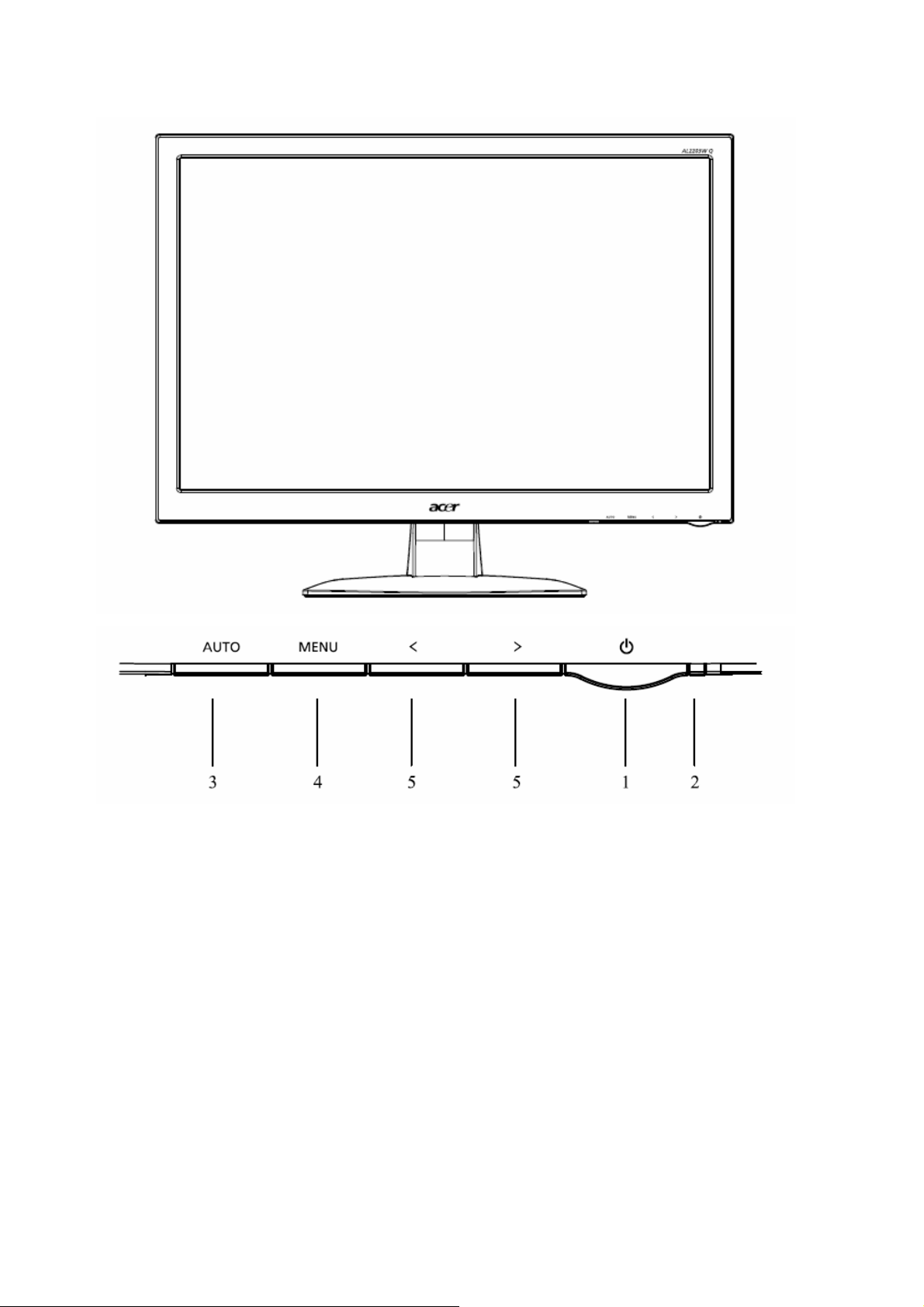
3. FRONT PANEL CONTROLS AND INDICATORS
3-1. User Control Buttons
1.Power Switch:
To turn ON or OFF the power.
2.Power LED:
Lights up to indicate the power is turned ON.
3.Auto Adjust button / Exit:
1)When OSD menu is in active status, this button will act as EXIT-KEY (EXIT OSD menu).
2)When OSD menu is in off status, press this button to activate the Auto Adjustment
function. The Auto Adjustment function is used to set the HPos, VPos, Clock and Focus.
5. < / >
1) When OSD menu is in active status, press < or > to select the desired function.
Press < or > to change the settings of the current function.
2) When OSD menu is in off status, press < or > to set the volume level.(Only Audio Model)
4.MENU / ENTER:
Activate OSD menu when OSD is OFF adjustment function when OSD is ON.
11
Page 12
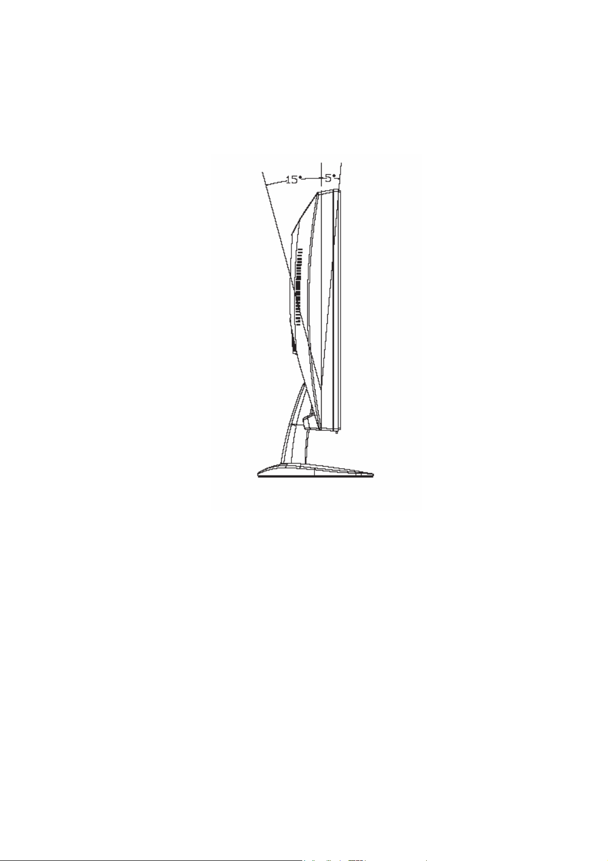
3-2 Tilting the Monitor
The monitor has a tilt feature that allows you to tilt the display back and forth to find the most
comfortable viewing position. To tilt the display, grasp the sides and push the display back or
pull it toward you until it is in the desired position. The display can be tilted 20º backward and
5º forward.
Note: Do not tilt the display by grasping the top edge.
12
Page 13
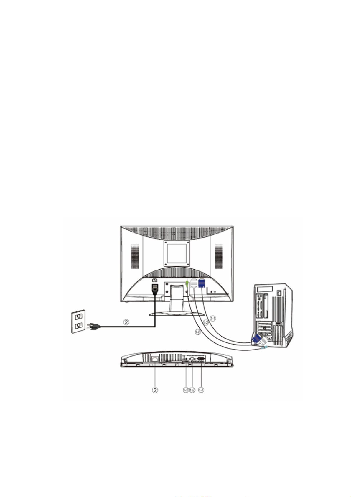
3-3 Connecting the Monitor
To install the monitor to your host system, please follow the steps as given
below:
Steps
1. Connect Video Cable
1-1 VGA Cable
a. Make sure both the monitor and computer are powered-OFF.
b. Connect the VGA video cable to the computer.
1-2 Digital Cable
a. Make sure both the monitor and computer are powered-OFF.
b. Connect one end of the 24-pin DVI cable to the back of the monitor and connect the other
end to the computer's port.
2. Connect power cord
Connect the power cord to the monitor, then to a properly grounded AC outlet.
3. Power-ON Monitor and Computer
Power-ON the monitor first, then power-ON the computer.
※This sequence is very important.
4. If the monitor still does not function properly, please refer to the troubleshooting section to
diagnose the problem.
Note: For best monitor performance, it is strongly recommended that you use Auto Configuration
to automatically configure your monitor’s settings.
13
Page 14

4. Circuit Description
The block diagram of LCD monitor is shown in Appendix A. Following is the brief description of
the electronic circuits.
1 Main board Circuit
The circuit diagrams of main board are shown in Appendix B (PWB-1195). The circuit
diagrams of key board (PWB-1220) show in Appendix F, and the circuit diagrams of Power
Board(PWB-1207) shown in Appendix D respectively.
1.1 Scalar: MST TSUMU58BWHJ
Refer TSUMU58BWHJ (LVDS) schematic. The analog R, G, B input signals are supplied from
the analog interface, and then fed into (PWB-1195) U401, (MST TSUMU58BWHJ located in
schematic) at pin 28, pin 25,pin 23 for R,G,B signals. These analog R, G, B, Video Signals are
converted to their digital forms in (PWB -1195) U401.
1. The H-SYNC and V-SYNC signals come from the analog interface, and fed into
(PWB-1195) U401 at pin 32, pin 33.
2. Signal SDA_VGA and SCL_VGA are communication lines between PC and
(PWB-1195) U302 (EDID for analog interface) which is located in the schematic. These
two lines are called I2C Bus in related technical literature, which is actually a firmed
industry standard.
3. DDCA_SCL, DDC_ASDA are 2 pairs of I2C BUS for DDC/CI controls between PC and
(PWB-1195) U401 which are located in the Schematic.
4. The signal Reset is activated while the monitor is power on. It forces (PWB-1195) U401 to
enter its reset status. After reset, (PWB-1195) U401 starts its normal operation.
5. (PWB-1195) X401 is a 14.318 MHZ crystal. It is associated circuit components provide the
required reference clock for (PWB-1195) U401 normal operation.
6.Key [Auto], [Menu],[-],[+],[ ], and LED signals are fed to schematic (PWB-1195) CN401
detecting the user key activity.
7. There are two LED drivers, (PWB-1195) Q403 Green and (PWB-1195) Q401Amber,
which are controlled by pin 124 and pin 123 of (PWB-1195) U401 respectively.
1.2 Analog Interface: Input Connector
Refer to (PWB-1195) CN301 in schematic.
1. The analog R, G, B video input signals are supplied through the cable which is
terminated at (PWB-1195) CN301.These input signals are approximately 0.7 VPP in
amplitude and protected by TVS array (PWB-1195) D306. These R, G, B video signals
are 75 ohm terminated to ground, via (PWB-1195) R305, R306, and R307, AC coupled via
0.047uF capacitors (PWB-1195) C301, C302 , C303, and finally fed into (PWB-1195)
U401, at pin 28, pin 25 and pin 23 respectively. These analog R, G, B video signals are
converted to their digital forms in (PWB-1195) U401.
2. The H-SYNC and V-SYNC signals of TTL level in amplitude and also protected by
14
Page 15

TVS array (PWB-1195) D307. These two signals are fed into(PWB-1195) U401, at pin 32,
pin 33.
3. The signals terminated at (PWB-1195) CN301, at pin 15, pin 12 are also protected by
(PWB-1195) D306, and then connected to (PWB-1195) U302, stores the EDID data that
serves for the purpose of plug and play functionality.
1.3 Digital Interface: Input Connector
Refer to (PWB-1195) CN302 in schematic.
1. Digitized video and sync information are serialized and sent over three sets of twisted pair
wires, one set for red, green and blue data channels. These Digital video signals are
transmitted through the cable which is terminated at (PWB-1195) CN302 and are
protected by TVS array (PWB-1195) D308, D309 finally fed into (PWB-1195) U401 at pin
9,pin 10,pin 12,pin 13,pin 15,and pin 16 respectively.
2. An additional pair of wires is used to transmit a clock signal for timing also protected by
TVS array (PWB-1195) D309. These clock signal is fed into(PWB-1195) U401, at pin 18,
pin 19.
3. The signals terminated at (PWB-1195) CN302, at pin 6, pin 7 are protected by TVS array
(PWB-1195) D310, and then connected to (PWB-1195) U301, stores the EDID data that
serves for the purpose of plug and play functionality.
4. The signals terminated at (PWB-1195) CN302, at pin 16 is also protected by TVS
array(PWB-1195) D310 that serves for the purpose of hot plug detect functionality.
1.4 Output interface
VLCD is fed from 5V via Q205.This voltage supply is controlled by control signal,
which comes from (PWB-1195) U401 and the digital video signals output from
(PWB-1195) U401, are divided into even and odd parts in LVDS format. They are
designated as RXO, and RXE, each of 8 bit width. These signals are fed into LCD panel
from (PWB-1195) CN502, with in located in Schematic.
1.5 Power & inverter Interface
For PI board PWB-1207, please refer to Schematic (PWB-1207) P851 is a connector
that connects main board and Power inverter board. Main board (PWB-1195) 5V is fed
from (PWB-1195) CN3 in Schematic and associated components.Regulator IC
(PWB-1195) U202 provides 3.3V , (PWB-1195)U201 provides 1.8V to U401.
2 Power and Inverter Board Circuit
The circuit diagram 2 in 1 of Power & inverter circuit is shown in Appendix D (PWB-1207).
The inverter supplies power for backlight for the LCD panel.
3 Key Board Circuit
The circuit diagram of key board circuit is shown in Appendix F (PWB-1220).
15
Page 16
4 Connector Definition
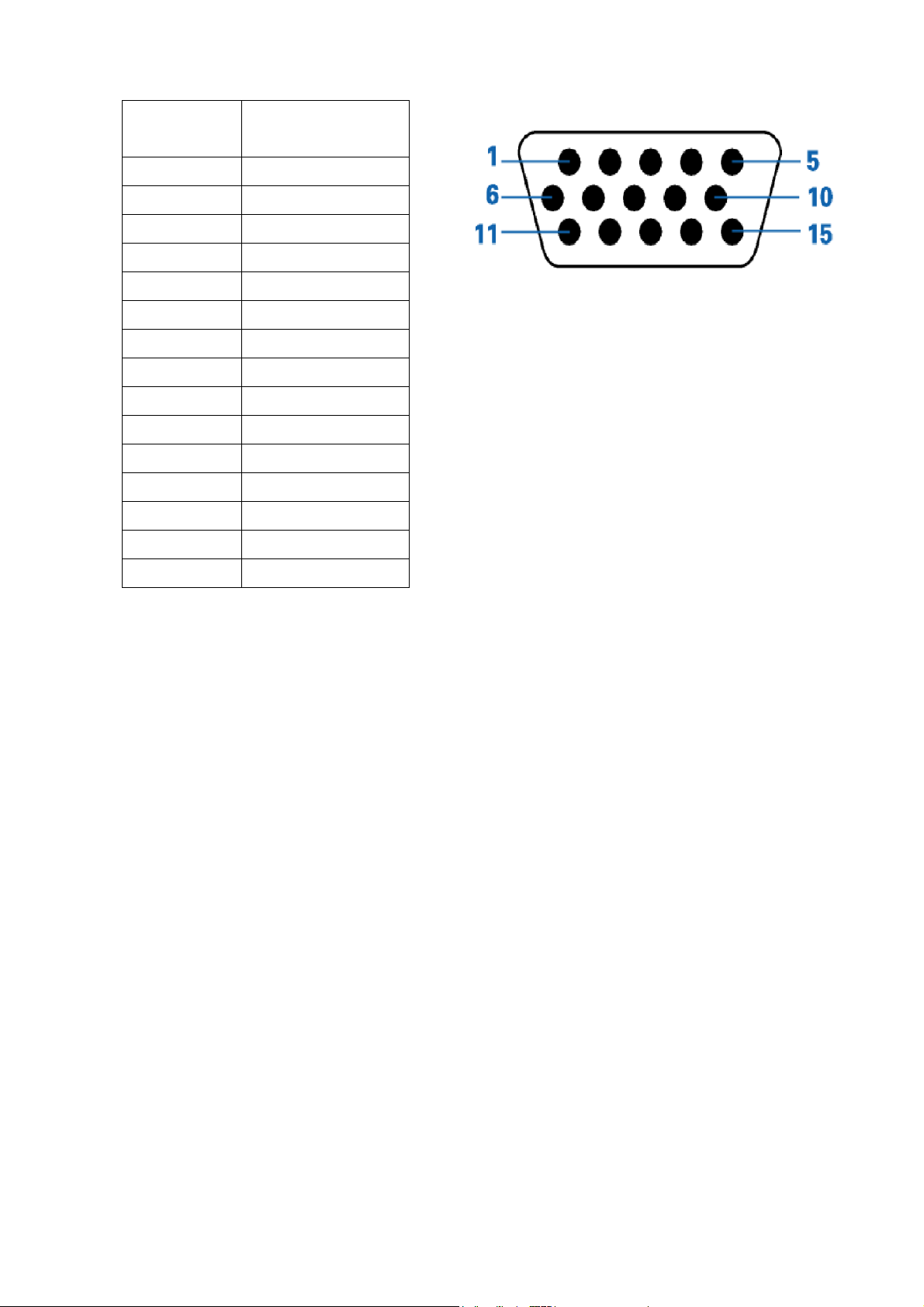
4.1 The pin assignment of the 15-pin D-SUB Receptacle connector is listed as below:
Pin
Number
Signal
Assignment
1 Video-Red
2 Video-Green
3 Video-Blue
4 Ground
5 Detect Cable
6 GND-R
7 GND-G
8 GND-B
9 +5V
10 Ground
11 Ground
12 DDC Data
13 H-Sync
14 V-Sync
15 DDC Clock
16
Page 17
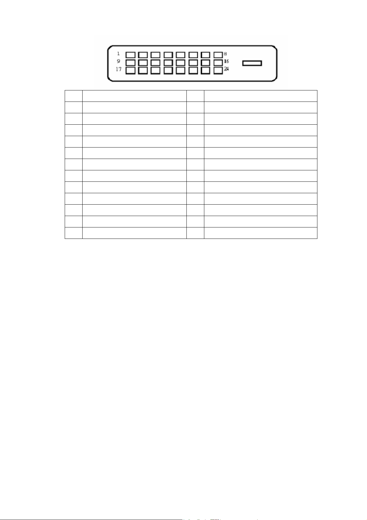
4.2 The pin assignment of the 24-pin DVI-D Receptacle connector is listed as below:
Pin Meaning Pin Meaning
1 TMDS Data2- 13 TMDS Data3+
2 TMDS Data2+ 14 +5V Power
3 TMDS Data 2/4 Shield 15 GND(return for +5V hsync.vsync
4 TMDS Data4- 16 Hot Plug Detect
5 TMDS Data4- 17 TMDS Data0-
6 DDC Clock 18 TMDS Data0+
7 DDC Data 19 TMDS Data 0/5
8 Analogue Vertical Sync 20 TMDS Data5-
9 TMDS Data1- 21 TMDS Data5+
10 TMDS Data1+ 22 TMDS Clock Shield
11 TMDS Data 1/3 Shield 23 TMDS Clock+
12 TMDS Data3- 24 DDC TMDS Clock-
17
Page 18
5. Adjusting Procedure.
Factory Mode Settings
5-1. Burn-in Mode
1. Do not connect any input source
2. Pressing button [ Menu ] then [ ] power on
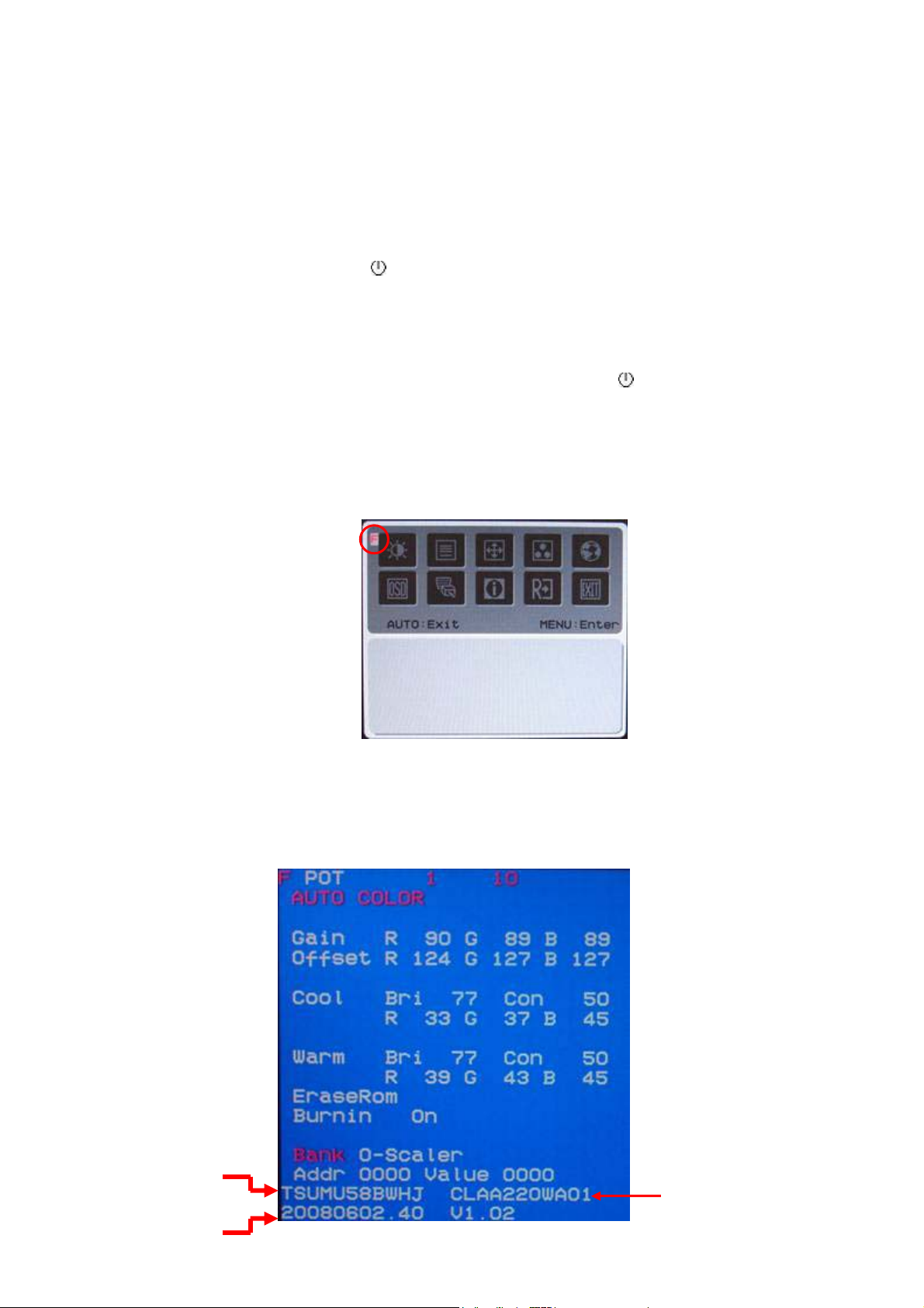
5-2. Enter into the factory setting:
1. Switch off the monitor, press and hold the [ Menu ] key then [ ] power on again
2. Press the [ Menu ] key to open OSD(OSD should be on the top left side of display), then
press the [<] key to select F of OSD and press [ Menu ] key into the factory OSD(factory
OSD in blue background is on the top left side of display)
3. Check the F/W version、type of panel 、type of scaler before execute AUTO COLOR or
adjusting color temperature.
4. Re-power on again, the monitor will reverse to normal operating state.
Type of scaler
F/W version
Type of Panel
18
Page 19
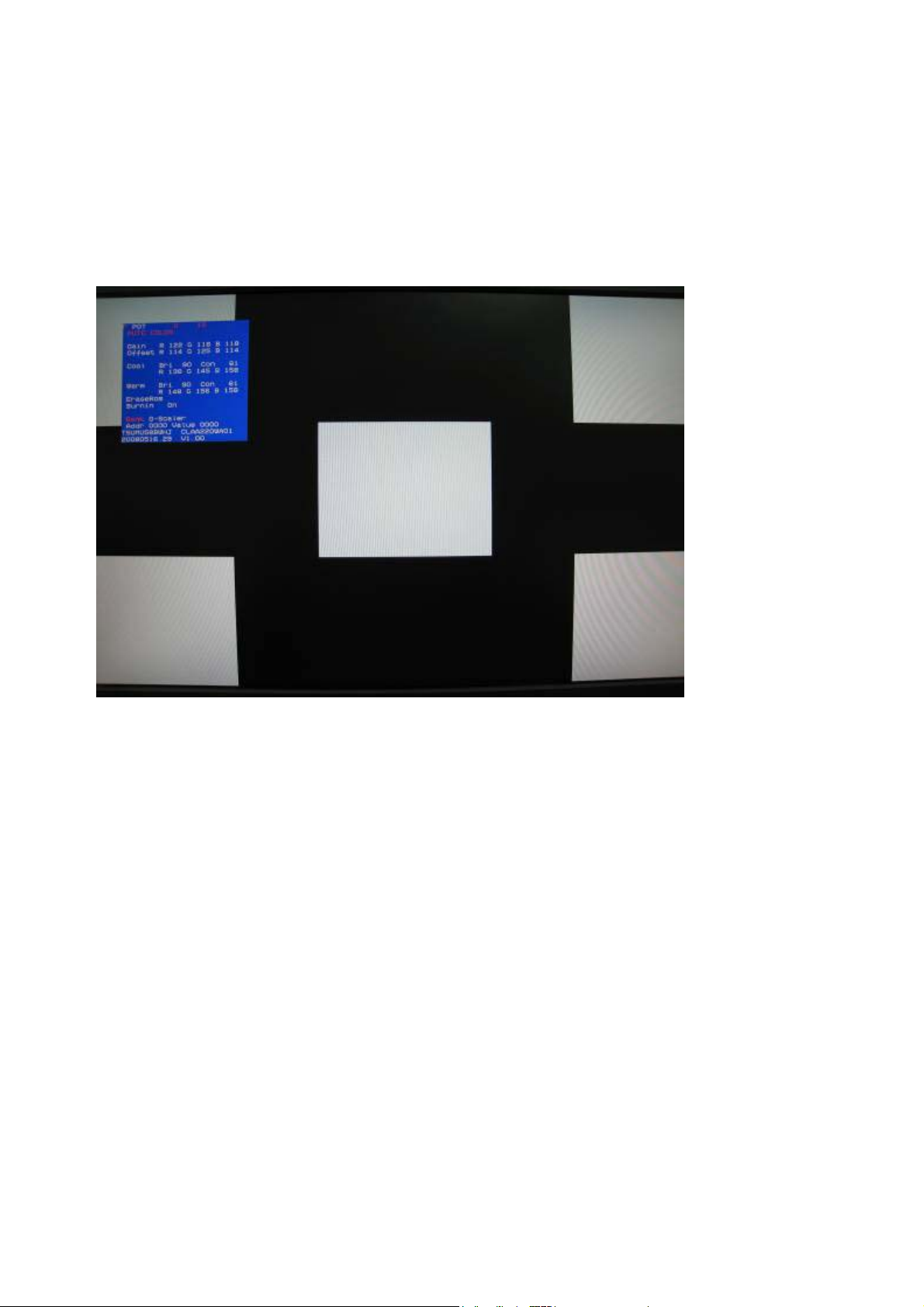
5-3. Auto-Color Adjustment (Factory Mode & VGA Input Only)
1. Enter the factory mode.
2. Apply a 65K Hz (1680x1050 / 60 Hz) signal with five white-block
pattern. .( CHROMA 2250 or equivalent ; Pattern #42)
3. Press “Auto Color” item of factory OSD to run Auto-Color Adjustment
5-4. White Balance Adjustment (Factory mode)
Please follow the steps to adjust White Balance of this monitor
1. Warm up the LCD monitor at least 30 minutes before the “Auto-Color
Adjustment” proceeds
2. Enter the factory mode
3. Apply a 65K Hz (1680x1050 / 60 Hz) signal with five squre white pattern.. ( CHROMA 2250
Pattern #42)
4. Execute the auto-color process first before adjusting the white balance
5. Press the “Reset “item of factory OSD to recall default Contrast/Brightness Value.
6. Use a color analyzer to set the Luminance & Color temperature to meet below data.
Color Temperature :
19
Page 20
Warm
x = 0.313 ± 0.020
y = 0.329 ± 0.020 Y ≧ 160cd/m2
Cool
x = 0.283 ± 0.020
y = 0.298 ± 0.020
* Adjusting by hand if Color Temperature is out of range.
7. Apply 1024x768 / 72 Hz then press the “Reset “item of factory OSD to initial
EEPROM for all timing modes.
8. Power off to end white balance adjustment.
5-5. Firmware Upgrade Procedure
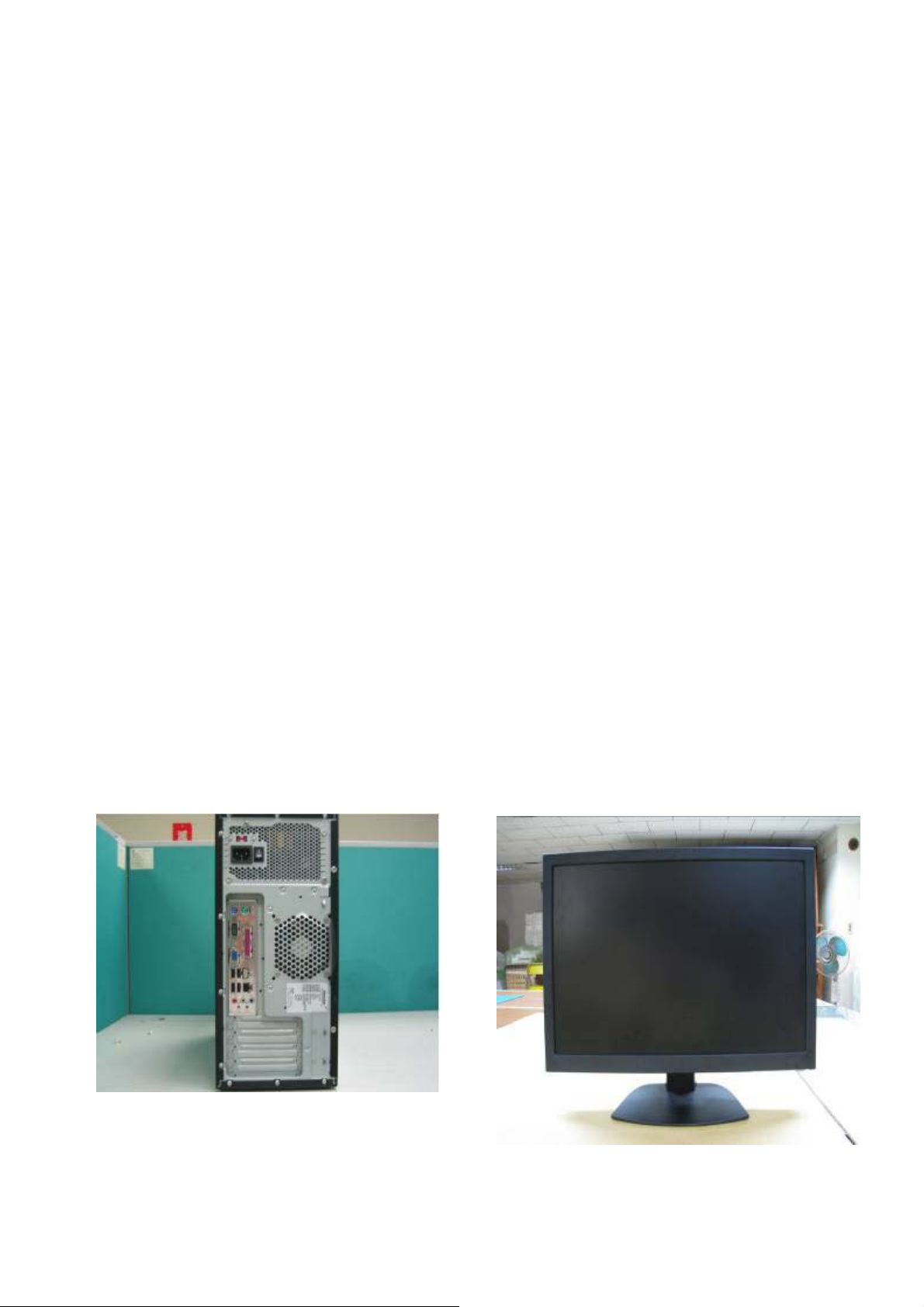
1. Equipment Request:
-PC(Personal Computer)
-Monitor(Waiting to Re-flash)
- ISP Burning Tool
-Power Adapter(Input: AC 100v~240v;Output: DC 12v)
-Print Port Cable
-VGA Cable
PC
Monitor
20
Page 21
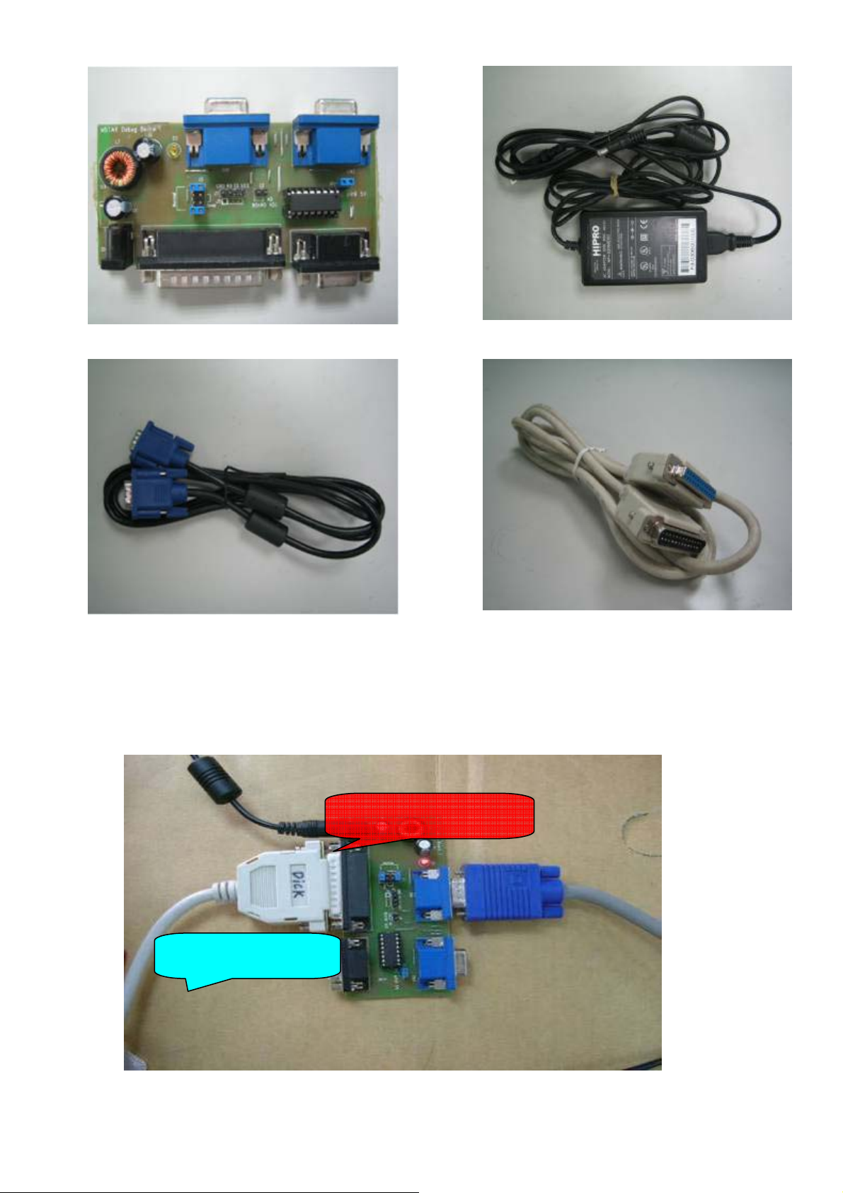
Power Adapter ISP Kit
VGA Cable
2.SOP to upgrade the firmware
Step1 Connect ISP kit between PC and monitor
DC 12V /1A(minimum)
Print Port Cable
Step 2. Execute ISP_Tool File
To PC Printer Port
21
Page 22
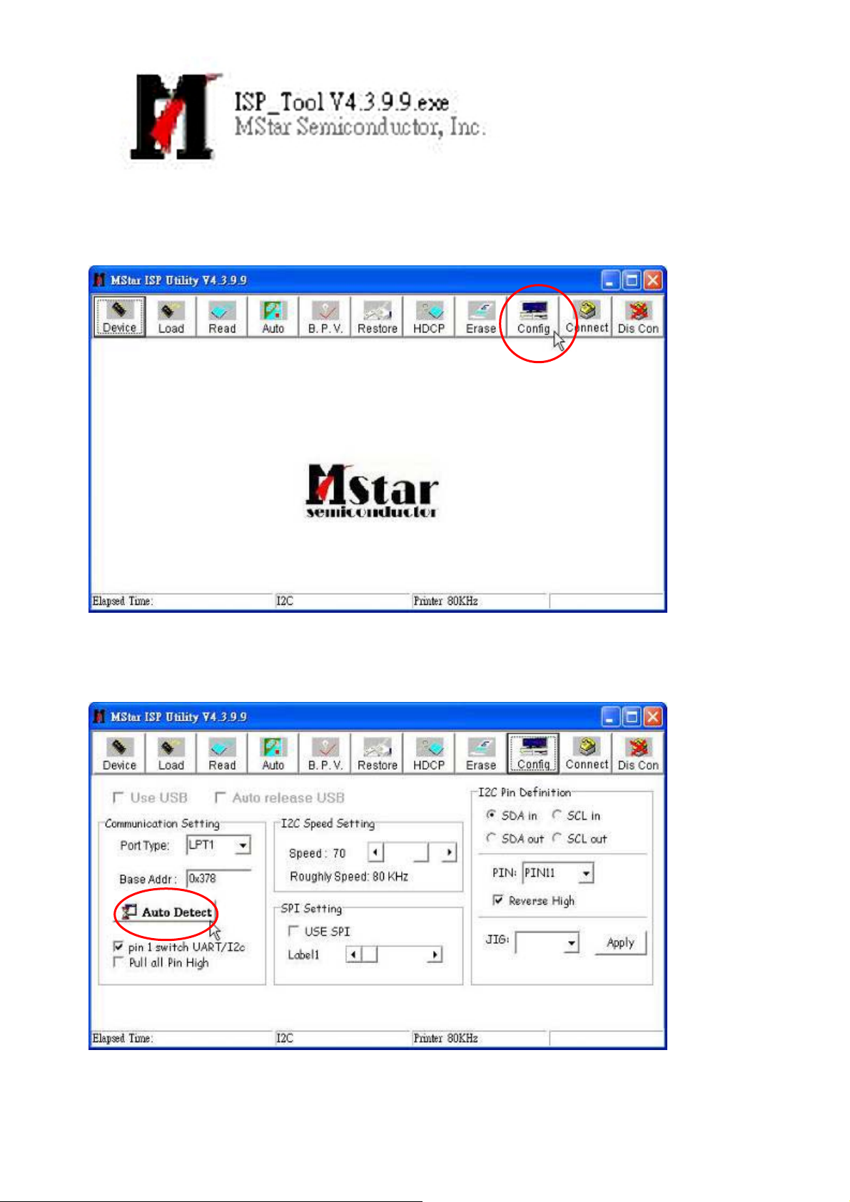
Step3.
Click ”Config”
Step 4.
Click “Auto Detect”
22
Page 23
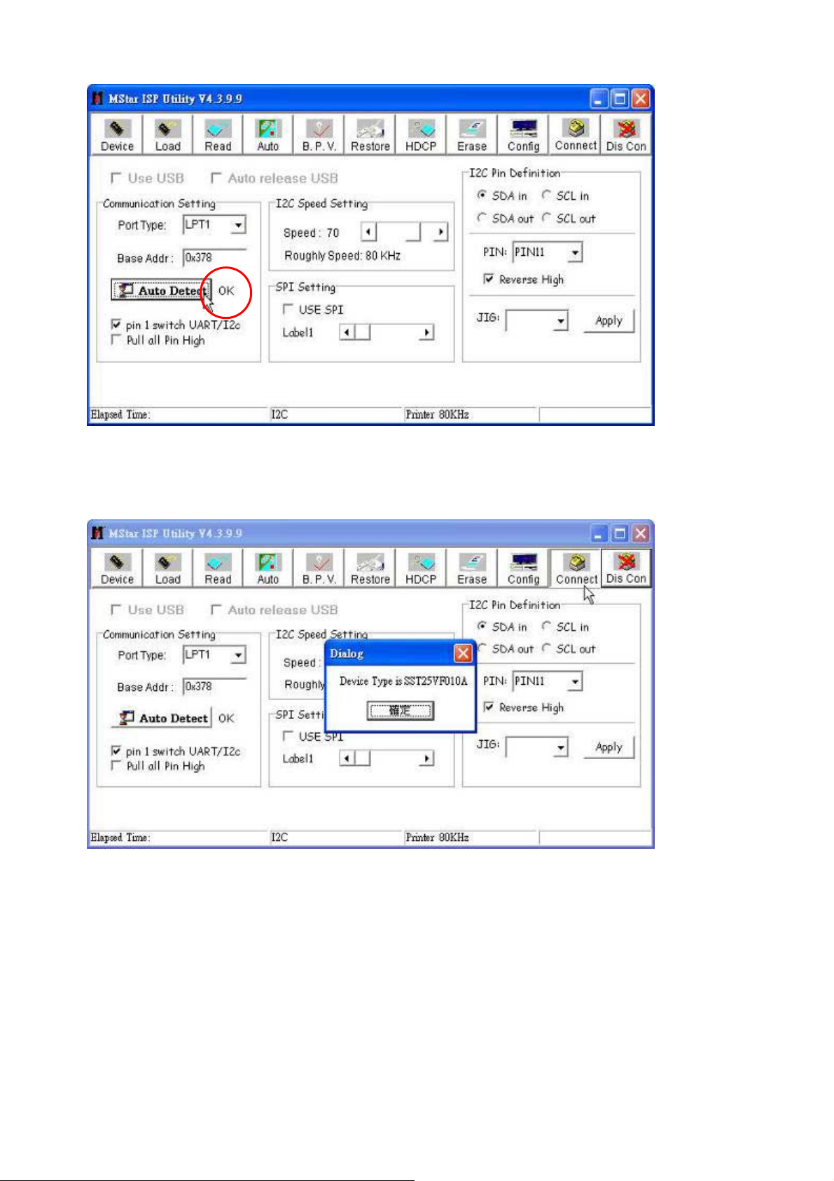
And then “OK” shows up beside the Auto Detect” button
Step 5.
Click “Connect” and then a dialog window pops up.
23
Page 24
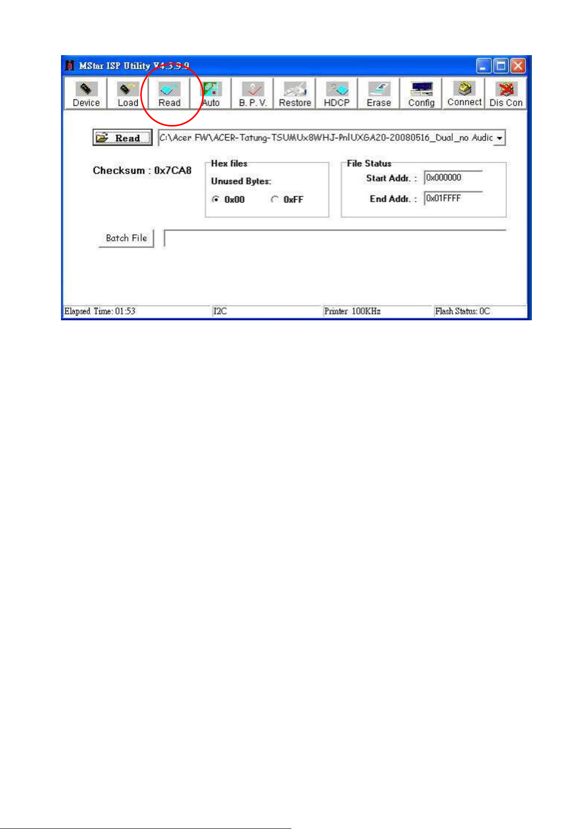
Step 6.
Click “Read” button
24
Page 25

Step 7.Click another “Read” button to find the folder where the BIN files are and select the correct
file for upgrade.
25
Page 26

Step 8.Click “Auto” button.
Step 9. Click “Run” button.
26
Page 27

When “Pass” message shows, the upgrade process has been done.
And then monitor goes to burn-in (self-test) mode.
5-6. Update the last version of program
※Each time the EEPROM MUST be initialed after upgradting to the latest firmware.
1. To initial the EEPROM:
When the monitor is in power off status, press [-] key once then press [+] key three times
key then press [ ] key to power on the monitor.
2. Repeat the procedure of 5-3. White Balance Adjustment to set the monitor to
correct color temperature.
27
Page 28

5-7. DDC Burn in Procedure 2.
1. Equipment Needed
- Acer AL2103W / 2203WQ Series Monitor.
-VGA Cable
-VGA board ( NVIDIA serials display card)
-PC (Personal Computer) with Win 98/ME, Best system operation under DOS.
-Power Adapter for PC and Monitor
-DDC Burn in Program
2. Setup Procedure
- 2.2.1 Connect Monitor VGA(DVI) input to PC’s VGA(DVI) ouput.
- 2.2.2 Plug Power Adapter to PC and Monitor
( NVIDIA GeForce series graphic
card is recommended )
28
Page 29

3. DDC Burn In Procedure
3.1 Ready
Extract “DDC for Acer.rar”. The content
is as right picture.
Note :
1. The graphic card must support VESA BIOS Extension/Serial Control Interface Standard
(VBE/SCI) function. ( nVidia GeForce series is recommended)
2. If your graphic card has VGA port only, you need a VGA to DVI converter.
3. The DDC burning-in process must be executed in the factory mode to remove writing
protection.
29
Page 30

3.2 Start Burn in EDID
Prepare a target monitor connected to VGA port of PC and follow below steps.
Step 1: Execute DDC
Step 2: Select ACER then Press Enter
The message mean display card support DDC2b+function and had over 2 ports number for
D-Sub or DVI port. If it appears “VBE/SCI Call Failed!”message, please try another display
card before next step.
30
Page 31

Step 3: Press F1 key in main menu. It will appear “Edit Parameter Item” sub menu. You can
modify the value of item [8] to burn EDID data from VGA port or DVI port.The value “1” means
VGA port and “2” means DVI port. If your graphic card has VGA port only, you need a VGA to
DVI converter.
Step 4: In main menu select item 3 then press enter key to enter “Select DDC function Mode”
sub menu .
31
Page 32

Step 5:In sub menu “Select DDC function Mode”,select item 5 then press enter key
to enter “Select DDC File Name” sub menu. Choose AL2103WA (that is
analog EDID for AL2103W model) then press enter key to exit “Select DDC File Name”
sub menu,
32
Page 33

Step 6:
Select item[ 2] then press Enter.
Step 7: Find monitor serial number from Monitor back label then scan the barcode. For
example the serial number QX6081800001 that means ttt is QX6, yy is 08. ww is 18 and sssss
is 00001. If barcode is scanned successfully, press enter to update EDID.
33
Page 34

Step 8:
Press F6 function key to see if the EDID is updated successfully.
If “Received DDC Data OK!!” message shows up that means the EDID is
updated successfully.
Step 9: Repeat step 5,choose AL2103WD for digital EDID and then go through
the rest steps to complete DDC updating.
34
Page 35

5-8. EDID Data
Supplier should update the ID code (byte 10-11), Manufacture Date (byte 16-17) and Serial
Number (byte 72-89).
※L22HCTN-URC Analog EDID Data (VGA)
*************************************************
* Acer Corporation *
* Date: Mon May 19, 2008 *
* EDID Version# 1, Revision# 3 *
* DDC/EDID/CEA861B Test for *
* AL2103W *
*************************************************
*128 BYTES OF EDID CODE:
*DDC 0 1 2 3 4 5 6 7 8 9 A B C D E F
0000 00 FF FF FF FF FF FF 00 04 72 EC AD FF FF 6F 81
0010 10 12 01 03 68 2F 1D 78 2A D5 25 A6 55 44 A1 25
0020 14 50 54 AF EF 80 81 C0 81 00 81 40 81 80 95 00
0030 95 0F A9 40 B3 00 21 39 90 30 62 1A 27 40 68 B0
0040 E6 04 D1 23 11 00 00 1C 00 00 00 FD 00 37 4C 1E
0050 4C 11 00 0A 20 20 20 20 20 20 00 00 00 FC 00 41
0060 4C 32 31 30 33 57 0A 20 20 20 20 20 00 00 00 FF
0070 00 4C 45 43 30 4E 30 30 32 39 33 30 30 0A 00 71
* EDID EXPLAIN:
*---- Header ---------------------------------------------------------------
*(0000-0007H) : [00 FF FF FF FF FF FF 00]
*---- Vendor/Product Identification ----------------------------------------
*(0008-0009H) : [04 72] ID Manufacturer Name......... = ACR
*(000A-000BH) : [EC AD] ID Product Code.............. = ADEC (HEX)
*(000C-000FH) : [FF FF 6F 81] ID Serial Number............. = 2171600895 (DEC)
*(0010H) : [10] Week of Manufacture.......... = 16
*(0011H) : [12] Year of Manufacture.......... = 2008
*---- Edid Version/Revision-------------------------------------------------
*(0012H) : [01] Version...................... = 1
*(0013H) : [03] Revision..................... = 3
*---- Basic Display Parameters/Features-------------------------------------
*(0014H) : [68] VIDEO INPUT DEFINITION :
* Signal Type................... = Analog
* Signal Level(Vp-p)............ = 0.700, 0.000
* Sparate Syncs.,
35
Page 36

*(0015H) : [2F] Max. Horizontal Image Size.... = 47 cm
*(0016H) : [1D] Max. Vertical Image Size...... = 29 cm
*(0017H) : [78] Display Gamma................. = 2.20
*(0018H) : [2A] DPMS SUPPORT FEATURE :
* Active-Off
* Display type : R/G/B Color
* Preferred Timing Mode
*---- Chroma Information ---------------------------------------------------
*(0019-0022H) : [D5 25 A6 55 44 A1 25 14 50 54]
* Red x = 0.651 Green x = 0.267 Blue x = 0.145 White x = 0.313
* Red y = 0.333 Green y = 0.630 Blue y = 0.080 White y = 0.329
*---- Detail Timing / Monitor Description-----------------------------------
* Established Timings :
*(0023-0025H) : [AF EF 80]
* 720 X 400 @ 70Hz
* 640 X 480 @ 60Hz
* 640 X 480 @ 72Hz
* 640 X 480 @ 75Hz
* 800 X 600 @ 56Hz
* 800 X 600 @ 60Hz
* 800 X 600 @ 72Hz
* 800 X 600 @ 75Hz
* 832 X 624 @ 75Hz
* 1024 X 768 @ 60Hz
* 1024 X 768 @ 70Hz
* 1024 X 768 @ 75Hz
* 1280 X1024 @ 75Hz
* 1152 X 870 @ 75Hz
* Standard Timings :
*(0026-0035H) : [81 C0 81 00 81 40 81 80 95 00 95 0F A9 40 B3 00]
* 1280 x 720 @ 60Hz
* 1280 x 800 @ 60Hz
* 1280 x 960 @ 60Hz
* 1280 x 1024 @ 60Hz
* 1440 x 900 @ 60Hz
* 1440 x 900 @ 75Hz
* 1600 x 1200 @ 60Hz
* 1680 x 1050 @ 60Hz
*---------------------------------------------------------------------------
* Detailed Timings #1 : Pixel Clock = 146.25 MHz
*(0036-0047H) : [21 39 90 30 62 1A 27 40 68 B0 E6 04 D1 23 11 00 00 1C]
* Horizontal:
36
Page 37

* Frequency.... = 65.29 KHz (-)
* Active Time.. = 1680 pixels Blanking Time..... = 560 pixels
* Sync Offset.. = 104 pixels Sync Pulse Width.. = 176 pixels
* Border....... = 0 pixels Image............. = 465 mm
* Vertical:
* Frequency.... = 59.95 Hz (+)
* Active Time.. = 1050 lines Blanking Time..... = 39 lines
* Sync Offset.. = 30 lines Sync Pulse Width.. = 6 lines
* Border....... = 0 lines Image............. = 291 mm
* Sync Configuration:
* Non-interlaced, No Stereo, Digital Separate,
* H. Polarity Negative, V. Polarity Positive
*---- Monitor Range Limits--------------------------------------------------
*(0048-0059H) : [00 00 00 FD 00 37 4C 1E 4C 11 00 0A 20 20 20 20 20 20]
* Vertical Frequency.............. = 55-76 Hz
* Horizontal Frequency............ = 30-76 KHz
* Maximum Supported Pixel Clock... = 170 MHz
* GTF - Start Frequency for Secondary Curve Not Defined
*---- Monitor Name ---------------------------------------------------------
*(005A-006BH) : [00 00 00 FC 00 41 4C 32 31 30 33 57 0A 20 20 20 20 20]
* AL2103W
*---- Monitor Serial Number ------------------------------------------------
*(006C-007DH) : [00 00 00 FF 00 4C 45 43 30 4E 30 30 32 39 33 30 30 0A]
* LEC0N0029300
*---- Extension flag -------------------------------------------------------
*(007EH) : [00] Unused Extension Block
*---- Checksum -------------------------------------------------------------
*(007FH) : [71] Checksum OK
*
*======================================================================
=====
*----- End Report -----
37
Page 38
※L22HCTN-URC Digital EDID Data (DVI)
*************************************************
* Unknown Model Corporation *
* Date: Mon May 19, 2008 *
* EDID Version# 1, Revision# 3 *
* DDC/EDID/CEA861B Test for *
* AL2103W *
*************************************************
*128 BYTES OF EDID CODE:
*DDC
0 1 2 3 4 5 6 7 8 9 A B C D E F
0000 00 FF FF FF FF FF FF 00 04 72 EC AD FF FF 6F 81
0010 10 12 01 03 80 2F 1D 78 2A D5 25 A6 55 44 A1 25
0020 14 50 54 AF EF 80 81 C0 81 00 81 40 81 80 95 00
0030 95 0F A9 40 B3 00 21 39 90 30 62 1A 27 40 68 B0
0040 E6 04 D1 23 11 00 00 1C 00 00 00 FD 00 37 4C 1E
0050 4C 11 00 0A 20 20 20 20 20 20 00 00 00 FC 00 41
0060 4C 32 31 30 33 57 0A 20 20 20 20 20 00 00 00 FF
0070 00 4C 45 43 30 4E 30 30 32 39 33 30 30 0A 00 59
* EDID EXPLAIN:
*---- Header ---------------------------------------------------------------
*(0000-0007H) : [00 FF FF FF FF FF FF 00]
*---- Vendor/Product Identification ----------------------------------------
*(0008-0009H) : [04 72] ID Manufacturer Name......... = ACR
*(000A-000BH) : [EC AD] ID Product Code.............. = ADEC (HEX)
*(000C-000FH) : [FF FF 6F 81] ID Serial Number............. = 2171600895 (DEC)
*(0010H) : [10] Week of Manufacture.......... = 16
*(0011H) : [12] Year of Manufacture.......... = 2008
*---- Edid Version/Revision-------------------------------------------------
*(0012H) : [01] Version...................... = 1
*(0013H) : [03] Revision..................... = 3
*---- Basic Display Parameters/Features-------------------------------------
*(0014H) : [80] VIDEO INPUT DEFINITION :
* Signal Type................... = Digital
*(0015H) : [2F] Max. Horizontal Image Size.... = 47 cm
*(0016H) : [1D] Max. Vertical Image Size...... = 29 cm
*(0017H) : [78] Display Gamma................. = 2.20
*(0018H) : [2A] DPMS SUPPORT FEATURE :
* Active-Off
* Display type : R/G/B Color
* Preferred Timing Mode
38
Page 39

*---- Chroma Information ---------------------------------------------------
*(0019-0022H) : [D5 25 A6 55 44 A1 25 14 50 54]
* Red x = 0.651 Green x = 0.267 Blue x = 0.145 White x = 0.313
* Red y = 0.333 Green y = 0.630 Blue y = 0.080 White y = 0.329
*---- Detail Timing / Monitor Description-----------------------------------
* Established Timings :
*(0023-0025H) : [AF EF 80]
* 720 X 400 @ 70Hz
* 640 X 480 @ 60Hz
* 640 X 480 @ 72Hz
* 640 X 480 @ 75Hz
* 800 X 600 @ 56Hz
* 800 X 600 @ 60Hz
* 800 X 600 @ 72Hz
* 800 X 600 @ 75Hz
* 832 X 624 @ 75Hz
* 1024 X 768 @ 60Hz
* 1024 X 768 @ 70Hz
* 1024 X 768 @ 75Hz
* 1280 X1024 @ 75Hz
* 1152 X 870 @ 75Hz
* Standard Timings :
*(0026-0035H) : [81 C0 81 00 81 40 81 80 95 00 95 0F A9 40 B3 00]
* 1280 x 720 @ 60Hz
* 1280 x 800 @ 60Hz
* 1280 x 960 @ 60Hz
* 1280 x 1024 @ 60Hz
* 1440 x 900 @ 60Hz
* 1440 x 900 @ 75Hz
* 1600 x 1200 @ 60Hz
* 1680 x 1050 @ 60Hz
*---------------------------------------------------------------------------
* Detailed Timings #1 : Pixel Clock = 146.25 MHz
*(0036-0047H) : [21 39 90 30 62 1A 27 40 68 B0 E6 04 D1 23 11 00 00 1C]
* Horizontal:
* Frequency.... = 65.29 KHz (-)
* Active Time.. = 1680 pixels Blanking Time..... = 560 pixels
* Sync Offset.. = 104 pixels Sync Pulse Width.. = 176 pixels
* Border....... = 0 pixels Image............. = 465 mm
* Vertical:
* Frequency.... = 59.95 Hz (+)
* Active Time.. = 1050 lines Blanking Time..... = 39 lines
39
Page 40

* Sync Offset.. = 30 lines Sync Pulse Width.. = 6 lines
* Border....... = 0 lines Image............. = 291 mm
* Sync Configuration:
* Non-interlaced, No Stereo, Digital Separate,
* H. Polarity Negative, V. Polarity Positive
*---- Monitor Range Limits--------------------------------------------------
*(0048-0059H) : [00 00 00 FD 00 37 4C 1E 4C 11 00 0A 20 20 20 20 20 20]
* Vertical Frequency.............. = 55-76 Hz
* Horizontal Frequency............ = 30-76 KHz
* Maximum Supported Pixel Clock... = 170 MHz
* GTF - Start Frequency for Secondary Curve Not Defined
*---- Monitor Name ---------------------------------------------------------
*(005A-006BH) : [00 00 00 FC 00 41 4C 32 31 30 33 57 0A 20 20 20 20 20]
* AL2103W
*---- Monitor Serial Number ------------------------------------------------
*(006C-007DH) : [00 00 00 FF 00 4C 45 43 30 4E 30 30 32 39 33 30 30 0A]
* LEC0N0029300
*---- Extension flag -------------------------------------------------------
*(007EH) : [00] Unused Extension Block
*---- Checksum -------------------------------------------------------------
*(007FH) : [59] Checksum OK
*
*======================================================================
=====
*----- End Report -----
40
Page 41

5-9. Disassembly Instructions
Follow the steps as below to disassemble the monitor
1. Face down the Monitor
Face down the monitor on a smooth plane with a soft material for protecting the faceplate
2. Remove the Hinge
Remove the hinge through removing the 4 fixed screws .Then pull over the hinge.
41
Page 42

3. Remove the Back cover
Remove the 2 fixed screws first, then use the proper Slotted Screwdriver to insert the gap
between front & Back cover & open
4. Separate the metal cover and panel
Separate the metal cover and panel by removing the 2 fixed screws with Philips Screwdriver
first (Red circle), then pull out the 4 connectors carefully (Blue circle), finally separate all tape
between metal cover and panel
5. Take out the PCB
Loosen the 2 Bolt screws (Blue circle)
42
Page 43

5-10. Packing For Shipping Procedure
1. Separate Stand from the Unit (Figure 1)
2. Put the monitor in the PE bag seal the bag with tape (Figure 2)
Figure 1
3. Put the cushions on the monitor. (Figure 3)
4. Place the monitor into the carton and then put all the accessories into the box. & seal the carton with
tape. (Figure 4)
Figure 3
Figure 2
Figure 4
43
Page 44
y
S
p
g
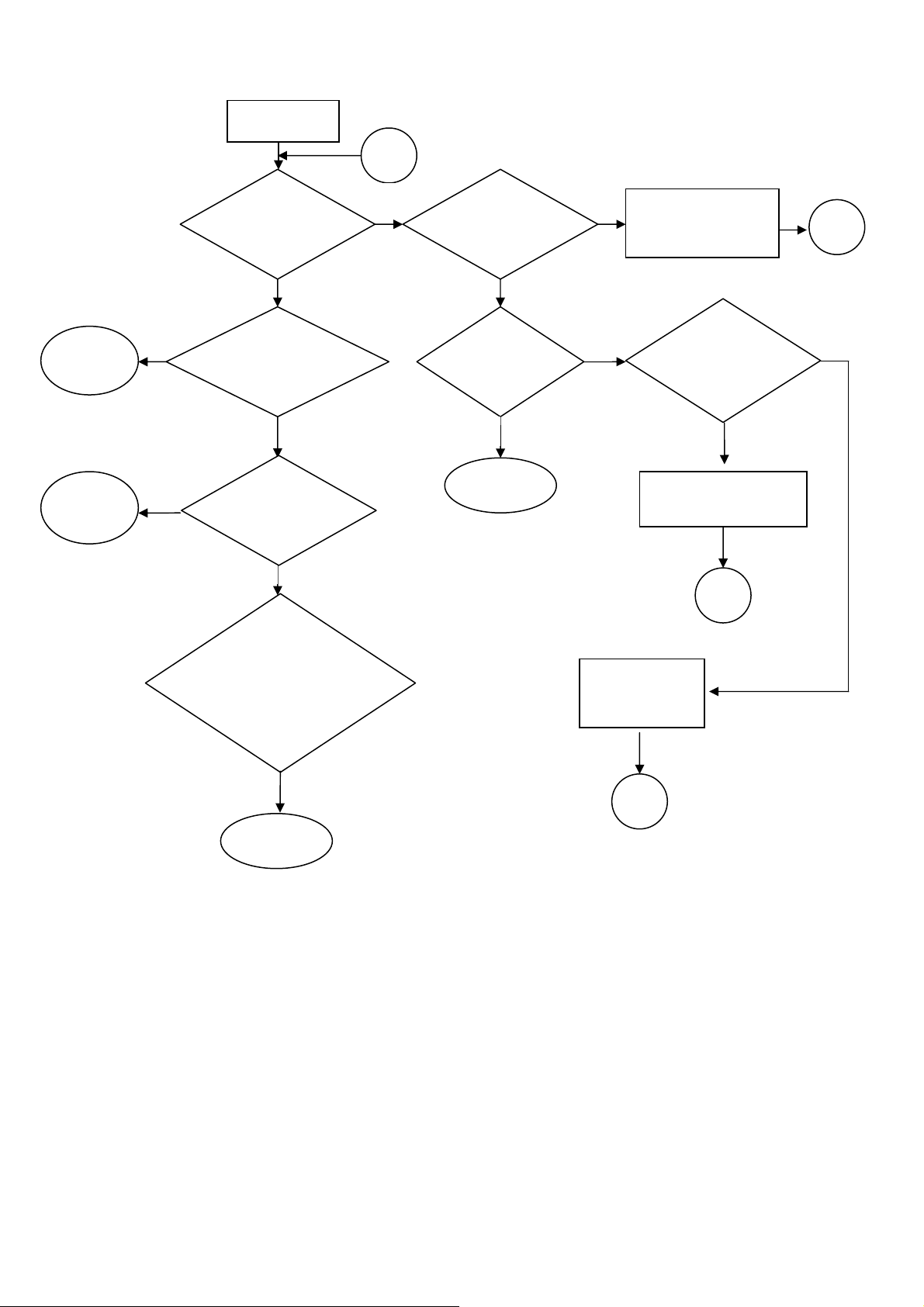
6. Trouble shooting Flow Chart
No Picture
A
NEXT1
NEXT2
No
No
Does the LED
light up?
YES YE
LED display is
amber?
Is it enter
ower savin
YES
Restart PC signal to
ensure H.V.sync are
correct.
Check Power is
correct of
Press power
ke
END
NoNo
Replace new power
and inverter board
No
Replace new main board
Replace key
board or key wire
A
No
Check control
key logic at
A
A
END
44
Page 45

NEXT1
NEXT2
Check the CN201
Voltage is correct
Replace new main
board
A
YES
No
Replace new
power board
A
Is it at sleep
mode?
YES
Release sleep mode
END
No
Replace new
main board
A
45
Page 46

7 Block Diagram
Speakers
Power
Interface
Audio Out
Audio In
VGA In
Panel Control
Regulator 1V8
+5V
+12V
AUDIO IC
Regulator 3V3
EDID
D-Sub
AUTO
MENU
+
POWER
-
Audio_ON/OFF
Volum Control
DDCA_SCL
DDCA_SDA
RGB Format
DET_VGA
Front Cover Control
1V8
3V3
Scaler
TSUMU18BWJ-LF
SOD
CSZ
SCK
SDI
Flash Memory
Backlight
LVDS Format
ON/OFF
LED_A
LED_A
LED_G
LED_G
VLCD
(Panel Power)
+5V
LED Indicator
LED Indicator
CPT Panel
Page 47

47
Page 48

48
Page 49

49
Page 50

50
Page 51

51
Page 52

52
Page 53

9.PCB Layout Diagrams
PWB-1195 : TOP BTM:
PWB-1220 :
TOP
BTM
53
Page 54

PWB-1207
54
Page 55

10. PWB-1195 BOM List
PWB-1195 (VGA + DVI) P/N:5097700804
CKT No Replace ID Part Spec Part No
- -
- -
-
C201
-
C202
-
C203
-
C204
-
C209
-
C210
ASSEMBLY,AS/WS
5095555501
L22HCTN
ASSEMBLY,PCB-MAIN
5097700804
PWB-1195
CAPACITOR,MONOLITHIC SMD REEL E230008891
Y5V DC 16V 1.00UFZ T 0603 -
CAPACITOR,MONOLITHIC SMD REEL E250610491
Y5V DC 50V 0.10UFZ T 0603 -
CAPACITOR,ELECTROLYTIC (105C) E214028702
CE04W 25V 100.00UFM * 6.3x11 -
CAPACITOR,MONOLITHIC SMD REEL E250610491
Y5V DC 50V 0.10UFZ T 0603 -
CAPACITOR,MONOLITHIC SMD REEL E250610491
Y5V DC 50V 0.10UFZ T 0603 -
CAPACITOR,MONOLITHIC SMD REEL E230029391
X7R 10V 10.00UFK T 1206 -
C214
C215
C216
C217
C218
C220
C222
C223
-
-
-
-
-
-
-
-
CAP.,ELEC. LOW ESR 105C KY E216030402
CE04CH 25V 220.00UFM * 8x11.5 -
CAPACITOR,MONOLITHIC SMD REEL E250610491
Y5V DC 50V 0.10UFZ T 0603 -
CAPACITOR,MONOLITHIC SMD REEL E250610491
Y5V DC 50V 0.10UFZ T 0603 -
CAPACITOR,MONOLITHIC SMD REEL E230008891
Y5V DC 16V 1.00UFZ T 0603 -
CAPACITOR,ELECTROLYTIC(105C) E214030902
CE04W 16V 100.00UFM * 5x11 -
CAP.,ELEC. LOW ESR 105C KY E216030402
CE04CH 25V 220.00UFM * 8x11.5 -
CAPACITOR,MONOLITHIC SMD REEL E250610491
Y5V DC 50V 0.10UFZ T 0603 -
CAPACITOR,MONOLITHIC SMD REEL E250610491
Y5V DC 50V 0.10UFZ T 0603 -
C301
C302
C303
C304
-
-
-
-
CAPACITOR,MONOLITHIC SMD REEL E230647391
X7R DC 50V47000.00pFK T 0603 -
CAPACITOR,MONOLITHIC SMD REEL E230647391
X7R DC 50V47000.00pFK T 0603 -
CAPACITOR,MONOLITHIC SMD REEL E230647391
X7R DC 50V47000.00pFK T 0603 -
CAPACITOR,MONOLITHIC SMD REEL E230610291
X7R 50V 1000.00PF K 0603 -
Page 56

C305
-
CAPACITOR,MONOLITHIC SMD REEL E230647391
X7R DC 50V47000.00pFK T 0603 -
C306
C307
C311
C312
C313
C314
C315
C330
-
-
-
-
-
-
-
-
CAPACITOR,MONOLITHIC SMD REEL E230647391
X7R DC 50V47000.00pFK T 0603 -
CAPACITOR,MONOLITHIC SMD REEL E230647391
X7R DC 50V47000.00pFK T 0603 -
CAPACITOR,MONOLITHIC SMD REEL E240647091
NPO 50V 47.00PFJ T 0603 -
CAPACITOR,MOLITHIC SMD REEL E240622191
NPO 50V 220.00PFJ T 0603 -
CAPACITOR,MONOLITHIC SMD REEL E250610491
Y5V DC 50V 0.10UFZ T 0603 -
CAPACITOR,MONOLITHIC SMD REEL E250610491
Y5V DC 50V 0.10UFZ T 0603 -
CAPACITOR,MONOLITHIC SMD REEL E250610491
Y5V DC 50V 0.10UFZ T 0603 -
CAPACITOR,MONOLITHIC SMD REEL E250610491
Y5V DC 50V 0.10UFZ T 0603 -
C331
C332
C333
C334
C401
C402
C403
C404
-
-
-
-
-
-
-
-
CAPACITOR,MONOLITHIC SMD REEL E250610491
Y5V DC 50V 0.10UFZ T 0603 -
CAPACITOR,MONOLITHIC SMD REEL E250610491
Y5V DC 50V 0.10UFZ T 0603 -
CAPACITOR,MONOLITHIC SMD REEL E250610491
Y5V DC 50V 0.10UFZ T 0603 -
CAPACITOR,MONOLITHIC SMD REEL E250610491
Y5V DC 50V 0.10UFZ T 0603 -
CAPACITOR,MONOLITHIC SMD REEL E250610491
Y5V DC 50V 0.10UFZ T 0603 -
CAPACITOR,MONOLITHIC SMD REEL E250610491
Y5V DC 50V 0.10UFZ T 0603 -
CAP.,ELEC. LOW ESR 105C KY E216033602
CE04CH 50V 4.70UFM * 5x11mm -
CAPACITOR,MONOLITHIC SMD REEL E250610491
Y5V DC 50V 0.10UFZ T 0603 -
C405
C406
C407
-
-
-
CAPACITOR,MONOLITHIC SMD REEL E250610491
Y5V DC 50V 0.10UFZ T 0603 -
CAPACITOR,MONOLITHIC SMD REEL E250610491
Y5V DC 50V 0.10UFZ T 0603 -
CAPACITOR,MONOLITHIC SMD REEL E250610491
Y5V DC 50V 0.10UFZ T 0603 -
56
Page 57

C408
RA
CAP.,ELEC. LOW ESR 105C KY E216022102
CE04CH 50V 10.00UFM * 5X11 -
C408
C409
C410
C411
C412
C413
C414
C415
RB
-
-
-
-
-
-
-
CAP.,ELEC. LOW ESR 105C KMY E216033702
CE04CH 50V 10.00UFM * 5x11mm -
CAPACITOR,MONOLITHIC SMD REEL E250610491
Y5V DC 50V 0.10UFZ T 0603 -
CAPACITOR,MONOLITHIC SMD REEL E250610491
Y5V DC 50V 0.10UFZ T 0603 -
CAPACITOR,MONOLITHIC SMD REEL E250610491
Y5V DC 50V 0.10UFZ T 0603 -
CAPACITOR,MONOLITHIC SMD REEL E250610491
Y5V DC 50V 0.10UFZ T 0603 -
CAPACITOR,MONOLITHIC SMD REEL E250610491
Y5V DC 50V 0.10UFZ T 0603 -
CAPACITOR,MONOLITHIC SMD REEL E250610491
Y5V DC 50V 0.10UFZ T 0603 -
CAPACITOR,MONOLITHIC SMD REEL E250610491
Y5V DC 50V 0.10UFZ T 0603 -
C416
C417
C418
C418
C419
C420
C421
C423
-
-
RA
RB
-
-
-
-
CAPACITOR,MONOLITHIC SMD REEL E250610491
Y5V DC 50V 0.10UFZ T 0603 -
CAPACITOR,MONOLITHIC SMD REEL E250610491
Y5V DC 50V 0.10UFZ T 0603 -
CAP.,ELEC. LOW ESR 105C KY E216022102
CE04CH 50V 10.00UFM * 5X11 -
CAP.,ELEC. LOW ESR 105C KMY E216033702
CE04CH 50V 10.00UFM * 5x11mm -
CAPACITOR,MONOLITHIC SMD REEL E250610491
Y5V DC 50V 0.10UFZ T 0603 -
CAPACITOR,MONOLITHIC SMD REEL E250610491
Y5V DC 50V 0.10UFZ T 0603 -
CAPACITOR,MONOLITHIC SMD REEL E240633091
NPO 50V 33.00PFJ T 0603 -
CAPACITOR,MONOLITHIC SMD REEL E240633091
NPO 50V 33.00PFJ T 0603 -
C425
C426
C427
-
-
-
CAPACITOR,MONOLITHIC SMD REEL E250610491
Y5V DC 50V 0.10UFZ T 0603 -
CAPACITOR,MONOLITHIC SMD REEL E250610491
Y5V DC 50V 0.10UFZ T 0603 -
CAPACITOR,MONOLITHIC SMD REEL E250610491
Y5V DC 50V 0.10UFZ T 0603 -
57
Page 58

C428
-
CAPACITOR,MONOLITHIC SMD REEL E250610491
Y5V DC 50V 0.10UFZ T 0603 -
C429
C431
C432
C433
CN201
CN301
CN301
CN302
-
-
-
-
-
RA
RB
-
CAPACITOR,MONOLITHIC SMD REEL E250610491
Y5V DC 50V 0.10UFZ T 0603 -
CAPACITOR,MONOLITHIC SMD REEL E250610491
Y5V DC 50V 0.10UFZ T 0603 -
CAPACITOR,MONOLITHIC SMD REEL E250610491
Y5V DC 50V 0.10UFZ T 0603 -
CAPACITOR,MONOLITHIC SMD REEL E250610491
Y5V DC 50V 0.10UFZ T 0603 -
CONNECTOR(BOX HEADER DIP)STM E782511039
12P,P=2.0mm-I,TIN -
CONNECTOR(D-SUB FEMALE)TEKCON E782401036
15P,3ROW,G/F,R/A,DIP,ZINC -
CON(D-SUB SHORT BODY REC.PC99) E782401030
15P,3ROW,G/F,R/A,DIP -
CONNECTOR(DVI-D FEMALE)TEKCON E782401035
24P,R/A,G/F,IVORY,DIP,SHIELD -
CN401
CN502
D203
D304
D304
D304
D305
D305
-
-
-
RA
RB
RC
RA
RB
CONNECTOR(BOX HEADER DIP) E782561039
6P,P=1.5mm-I,V/T,TIN -
CONNECTOR(FPC/FFC BOTTOM)PTWO E782975004
30P,P=1.0mm-L,SMD,TIN,R/A,LOCK -
RESISTOR,THICK FILM CHIP 1206 E138600009
RMC 1/4W 0.00 J T -
DIODE ZENER SeCoS F615010051
MMSZ5232B SOD123 -
DIODE ZENER SMD REEL PANJIT F615020031
MMSZ5232B 5.6V 500mW SOD-123 -
DIODE ZENER SMD ROHM F615011553
RLZ5.6B 5.45V-5.73V 20mA LL-34 -
DIODE Schottky SMD SeCoS F611010011
BAT54C Dual 30V,0.2A SOT-23 -
DIODE Schottky SMD PANJIT F611020011
BAT54C SOT-23 -
D306
D307
D308
-
-
-
DIO.ESD PROTECT ARRAY AMAZING F615092500
AZ1045-04SU SOT23-6L FOR HDMI -
DIO.ESD PROTECT ARRAY AMAZING F615091000
AZC099-04S SOT23-6L -
DIO.ESD PROTECT ARRAY AMAZING F615091000
AZC099-04S SOT23-6L -
58
Page 59

D309
-
DIO.ESD PROTECT ARRAY AMAZING F615091000
AZC099-04S SOT23-6L -
D310
D311
D311
D323
D323
D401
D401
D402
-
RA
RB
RA
RB
RA
RB
RA
DIO.ESD PROTECT ARRAY AMAZING F615092500
AZ1045-04SU SOT23-6L FOR HDMI -
DIODE Schottky SMD SeCoS F611010011
BAT54C Dual 30V,0.2A SOT-23 -
DIODE Schottky SMD PANJIT F611020011
BAT54C SOT-23 -
DIODE ZENER SeCoS F615010091
BZT52C3V6 SOD123 -
DIODE ZENER SMD REEL PANJIT F615020041
MMSZ5227B 3.6V SOD-123 -
DIODE ZENER SeCoS F615010091
BZT52C3V6 SOD123 -
DIODE ZENER SMD REEL PANJIT F615020041
MMSZ5227B 3.6V SOD-123 -
DIODE ZENER SeCoS F615010051
MMSZ5232B SOD123 -
D402
D402
F201
FB301
FB302
FB303
FB304
FB401
RB
RC
-
-
-
-
-
-
DIODE ZENER SMD REEL PANJIT F615020031
MMSZ5232B 5.6V 500mW SOD-123 -
DIODE ZENER SMD ROHM F615011553
RLZ5.6B 5.45V-5.73V 20mA LL-34 -
RESISTOR,THICK FILM CHIP 1206 E138600009
RMC 1/4W 0.00 J T -
Core Ferrite Bead MagLaye E062132313
MLB-160808-0120B-N3 120 ohm Chip -
RESISTOR,THICK FILM CHIP 0603 E134600009
RMC 1/10W 0.00 J T -
RESISTOR,THICK FILM CHIP 0603 E134600009
RMC 1/10W 0.00 J T -
RESISTOR,THICK FILM CHIP 0603 E134600009
RMC 1/10W 0.00 J T -
RESISTOR,THICK FILM CHIP 0805 E137600009
RMC 1/8W 0.00 J T -
FB402
FB403
FB404
-
-
-
CORE,FERRITE BEAD 0805 MAGLAYE E062133028
MLB-201209-0030P-N1 30ohm 6A -
CORE,FERRITE BEAD 0805 MAGLAYE E062133028
MLB-201209-0030P-N1 30ohm 6A -
CORE,FERRITE BEAD 0805 MAGLAYE E062133028
MLB-201209-0030P-N1 30ohm 6A -
59
Page 60

FB405
-
CORE,FERRITE BEAD 0805 MAGLAYE E062133028
MLB-201209-0030P-N1 30ohm 6A -
L201
L202
Q201
Q201
Q201
Q202
Q202
Q202
-
-
RA
RB
RC
RA
RB
RC
Core Ferrite Bead Chip MagLayers E062122982
MLB-321611-0070P-N170 ohm -
Core Ferrite Bead MagLayers E062150016
MLB-201209-0300P-N2A 300ohm 4A -
TR NPN SMD ZOWIE F622002257
MMBT3904 SOT-23 40V 0.2A -
TR NPN SMD PANJIT F622020011
MMBT3904 40V 0.2A SOT-23 -
TR NPN SMD SeCoS F622010011
MMBT3904 0.2A 60V SOT-23 -
TR NPN SMD ZOWIE F622002257
MMBT3904 SOT-23 40V 0.2A -
TR NPN SMD PANJIT F622020011
MMBT3904 40V 0.2A SOT-23 -
TR NPN SMD SeCoS F622010011
MMBT3904 0.2A 60V SOT-23 -
Q203
Q203
Q203
Q205
Q205
Q301
Q301
Q301
RA
RB
RC
RA
RB
RA
RB
RC
TR NPN SMD ZOWIE F622002257
MMBT3904 SOT-23 40V 0.2A -
TR NPN SMD PANJIT F622020011
MMBT3904 40V 0.2A SOT-23 -
TR NPN SMD SeCoS F622010011
MMBT3904 0.2A 60V SOT-23 -
TR MOSFET P-CHANNEL AOS F626002856
AO3407L SOT-23 P-CH -
TR MOSFET P-CHANNEL AOS F626002853
AO3401L SOT-23 P-CH -
TR NPN SMD ZOWIE F622002257
MMBT3904 SOT-23 40V 0.2A -
TR NPN SMD PANJIT F622020011
MMBT3904 40V 0.2A SOT-23 -
TR NPN SMD SeCoS F622010011
MMBT3904 0.2A 60V SOT-23 -
Q401
Q401
Q402
RA
RB
RA
TR PNP SMD SeCoS F623010011
MMBT3906 SOT-23 -0.2A -50V -
TR PNP SMD PANJIT F623020011
MMBT3906 -40V -0.2A SOT-23 -
TR NPN SMD ZOWIE F622002257
MMBT3904 SOT-23 40V 0.2A -
60
Page 61

Q402
RB
TR NPN SMD PANJIT F622020011
MMBT3904 40V 0.2A SOT-23 -
Q402
Q403
Q403
Q601
Q601
Q601
R201
R202
RC
RA
RB
RA
RB
RC
-
-
TR NPN SMD SeCoS F622010011
MMBT3904 0.2A 60V SOT-23 -
TR PNP SMD SeCoS F623010011
MMBT3906 SOT-23 -0.2A -50V -
TR PNP SMD PANJIT F623020011
MMBT3906 -40V -0.2A SOT-23 -
TR NPN SMD ZOWIE F622002257
MMBT3904 SOT-23 40V 0.2A -
TR NPN SMD PANJIT F622020011
MMBT3904 40V 0.2A SOT-23 -
TR NPN SMD SeCoS F622010011
MMBT3904 0.2A 60V SOT-23 -
RESISTOR,THICK FILM CHIP 0603 E134610209
RMC 1/10W 1.00K J T -
RESISTOR,METAL OXIDE FILM,MINI E130451903
RS B 2WS 5.1 ohm J SL -
R203
R205
R206
R210
R211
R213
R214
R216
-
-
-
-
-
-
-
-
RESISTOR,THICK FILM CHIP 0603 E134624209
RMC 1/10W 2.40K J T -
RESISTOR,THICK FILM CHIP 0603 E134600009
RMC 1/10W 0.00 J T -
RESISTOR,THICK FILM CHIP 0603 E134600009
RMC 1/10W 0.00 J T -
RESISTOR,THICK FILM CHIP 0603 E134610309
RMC 1/10W 10.00K J T -
RESISTOR,THICK FILM CHIP 0603 E134600009
RMC 1/10W 0.00 J T -
RESISTOR,THICK FILM CHIP 0603 E134610309
RMC 1/10W 10.00K J T -
RESISTOR,THICK FILM CHIP 0805 E137600009
RMC 1/8W 0.00 J T -
RESISTOR,THICK FILM CHIP 0603 E134600009
RMC 1/10W 0.00 J T -
R217
R218
R219
-
-
-
RESISTOR,THICK FILM CHIP 0603 E134647209
RMC 1/10W 4.70K J T -
RESISTOR,THICK FILM CHIP 0603 E134610309
RMC 1/10W 10.00K J T -
RESISTOR,THICK FILM CHIP 0603 E134633309
RMC 1/10W 33.00K J T -
61
Page 62

R220
-
RESISTOR,THICK FILM CHIP 0603 E134647209
RMC 1/10W 4.70K J T -
R222
R227
R301
R302
R303
R304
R305
R306
-
-
-
-
-
-
-
-
RESISTOR,THICK FILM CHIP 0603 E134647209
RMC 1/10W 4.70K J T -
RESISTOR THICK FILM CHIP 0603 E134668309
RMC 1/10W 68.00KJ T -
RESISTOR,THICK FILM CHIP 0603 E134647209
RMC 1/10W 4.70K J T -
RESISTOR,THICK FILM CHIP 0603 E134610109
RMC 1/10W 100.00 J T -
RESISTOR,THICK FILM CHIP 0603 E134610109
RMC 1/10W 100.00 J T -
RESISTOR,THICK FILM CHIP 0603 E134647109
RMC 1/10W 470.00 J T -
RESISTOR,THICK FILM CHIP 0603 E134275099
RMC 1/10W 75.00 F T -
RESISTOR,THICK FILM CHIP 0603 E134275099
RMC 1/10W 75.00 F T -
R307
R308
R309
R310
R311
R312
R313
R314
-
-
-
-
-
-
-
-
RESISTOR,THICK FILM CHIP 0603 E134275099
RMC 1/10W 75.00 F T -
RESISTOR,THICK FILM CHIP 0603 E134610109
RMC 1/10W 100.00 J T -
RESISTOR,THICK FILM CHIP 0603 E134610109
RMC 1/10W 100.00 J T -
RESISTOR,THICK FILM CHIP 0603 E134610109
RMC 1/10W 100.00 J T -
RESISTOR,THICK FILM CHIP 0603 E134610309
RMC 1/10W 10.00K J T -
RESISTOR,THICK FILM CHIP 0603 E134651009
RMC 1/10W 51.00 J T -
RESISTOR,THICK FILM CHIP 0603 E134610209
RMC 1/10W 1.00K J T -
RESISTOR,THICK FILM CHIP 0603 E134610209
RMC 1/10W 1.00K J T -
R315
R316
R319
-
-
-
RESISTOR,THICK FILM CHIP 0603 E134622209
RMC 1/10W 2.20K J T -
RESISTOR,THICK FILM CHIP 0603 E134622209
RMC 1/10W 2.20K J T -
RESISTOR,THICK FILM CHIP 0603 E134647209
RMC 1/10W 4.70K J T -
62
Page 63

R320
-
RESISTOR,THICK FILM CHIP 0603 E134610109
RMC 1/10W 100.00 J T -
R321
R322
R323
R324
R325
R328
R329
R330
-
-
-
-
-
-
-
-
RESISTOR,THICK FILM CHIP 0603 E134610109
RMC 1/10W 100.00 J T -
RESISTOR,THICK FILM CHIP 0603 E134610109
RMC 1/10W 100.00 J T -
RESISTOR,THICK FILM CHIP 0603 E134610109
RMC 1/10W 100.00 J T -
RESISTOR,THICK FILM CHIP 0603 E134610309
RMC 1/10W 10.00K J T -
RESISTOR,THICK FILM CHIP 0603 E134610109
RMC 1/10W 100.00 J T -
RESISTOR,THICK FILM CHIP 0603 E134647209
RMC 1/10W 4.70K J T -
RESISTOR,THICK FILM CHIP 0603 E134610009
RMC 1/10W 10.00 J T -
RESISTOR,THICK FILM CHIP 0603 E134610009
RMC 1/10W 10.00 J T -
R331
R332
R333
R334
R335
R336
R337
R338
-
-
-
-
-
-
-
-
RESISTOR,THICK FILM CHIP 0603 E134610009
RMC 1/10W 10.00 J T -
RESISTOR,THICK FILM CHIP 0603 E134610009
RMC 1/10W 10.00 J T -
RESISTOR,THICK FILM CHIP 0603 E134610009
RMC 1/10W 10.00 J T -
RESISTOR,THICK FILM CHIP 0603 E134610009
RMC 1/10W 10.00 J T -
RESISTOR,THICK FILM CHIP 0603 E134610009
RMC 1/10W 10.00 J T -
RESISTOR,THICK FILM CHIP 0603 E134610009
RMC 1/10W 10.00 J T -
RESISTOR,THICK FILM CHIP 0603 E134610209
RMC 1/10W 1.00K J T -
RESISTOR,THICK FILM CHIP 0603 E134610309
RMC 1/10W 10.00K J T -
R341
R401
R402
-
-
-
RESISTOR,THICK FILM CHIP 0603 E134610109
RMC 1/10W 100.00 J T -
RESISTOR,THICK FILM CHIP 0603 E134239209
RMC 1/10W 392.00 F T -
RESISTOR,THICK FILM CHIP 0603 E134610309
RMC 1/10W 10.00K J T -
63
Page 64

R403
-
RESISTOR,THICK FILM CHIP 0603 E134647209
RMC 1/10W 4.70K J T -
R406
R407
R409
R411
R412
R413
R414
R416
-
-
-
-
-
-
-
-
RESISTOR,THICK FILM CHIP 0603 E134611209
RMC 1/10W 1.10K J T -
RESISTOR,THICK FILM CHIP 0603 E134610109
RMC 1/10W 100.00 J T -
RESISTOR,THICK FILM CHIP 0603 E134610109
RMC 1/10W 100.00 J T -
RESISTOR,THICK FILM CHIP 0603 E134611209
RMC 1/10W 1.10K J T -
RESISTOR,THICK FILM CHIP 0603 E134610109
RMC 1/10W 100.00 J T -
RESISTOR,THICK FILM CHIP 0603 E134610309
RMC 1/10W 10.00K J T -
RESISTOR,THICK FILM CHIP 0603 E134639209
RMC 1/10W 3.90K J T -
RESISTOR,THICK FILM CHIP 0603 E134610109
RMC 1/10W 100.00 J T -
R419
R420
R421
R422
R424
R425
R427
R428
-
-
-
-
-
-
-
-
RESISTOR,THICK FILM CHIP 0603 E134622009
RMC 1/10W 22.00 J T -
RESISTOR,THICK FILM CHIP 0603 E134610209
RMC 1/10W 1.00K J T -
RESISTOR,THICK FILM CHIP 0603 E134610209
RMC 1/10W 1.00K J T -
RESISTOR,THICK FILM CHIP 0603 E134647209
RMC 1/10W 4.70K J T -
RESISTOR,THICK FILM CHIP 0603 E134647209
RMC 1/10W 4.70K J T -
RESISTOR,THICK FILM CHIP 0603 E134622009
RMC 1/10W 22.00 J T -
RESISTOR,THICK FILM CHIP 0603 E134647209
RMC 1/10W 4.70K J T -
RESISTOR,THICK FILM CHIP 0603 E134610109
RMC 1/10W 100.00 J T -
R430
R432
R436
-
-
-
RESISTOR,THICK FILM CHIP 0603 E134610109
RMC 1/10W 100.00 J T -
RESISTOR,THICK FILM CHIP 0603 E134610109
RMC 1/10W 100.00 J T -
RESISTOR,THICK FILM CHIP 0603 E134610309
RMC 1/10W 10.00K J T -
64
Page 65

R437
-
RESISTOR,THICK FILM CHIP 0603 E134600009
RMC 1/10W 0.00 J T -
R438
R439
R440
R441
R442
R443
U1195
U202
-
-
-
-
-
-
-
-
RESISTOR,THICK FILM CHIP 0603 E134647209
RMC 1/10W 4.70K J T -
RESISTOR,THICK FILM CHIP 0603 E134647209
RMC 1/10W 4.70K J T -
RESISTOR,THICK FILM CHIP 0603 E134600009
RMC 1/10W 0.00 J T -
RESISTOR,THICK FILM CHIP 0603 E134647209
RMC 1/10W 4.70K J T -
RESISTOR,THICK FILM CHIP 0603 E134647209
RMC 1/10W 4.70K J T -
RESISTOR,THICK FILM CHIP 0603 E134600009
RMC 1/10W 0.00 J T -
PCB,Main Board E053111950
PWB-1195 91x100mm*2pcs FR-4 2L -
IC,VOLTAGE REGULATOR DIODES F640031014
AP1117E18L-13 SOT-223-3L -
U203
U301
U301
U302
U302
U401
U402
U402
-
RA
RB
RA
RB
-
RA
RB
IC,VOLTAGE REGULATOR DIODES F640010150
AP1117E33L-13 SOT-223-3L -
IC,MEMORY EEPROM CATALYST F647051862
CAT24C02WI-GT3 SOIC-8 -
IC,MEMORY EEPROM 2K ROHM F647005555
BR24L02F-W SOP-8 SMD -
IC,MEMORY EEPROM CATALYST F647051862
CAT24C02WI-GT3 SOIC-8 -
IC,MEMORY EEPROM 2K ROHM F647005555
BR24L02F-W SOP-8 SMD -
IC,LSI SCALER MSTAR F647012788
TSUMU58BWHJ-LF PQFP-128 -
IC,CMOS FLASH MEMORY SST F647026865
SST25VF010A-33-4C-SAE SOIC-8 -
IC,SPI FLASH MEMORY 1Mb MXIC F647043179
MX25L1005MC-12G SOP-8 -
U403
X401
X401
-
RA
RB
IC,MEMORY EEPROM CATALYST F647026357
CAT24C16WI-GT3 SOIC-8 -
CRYSTAL UNIT H.ELE F699106505
14.31818MHZ CF:20PF,+-30PPM AT-49 -
CRYSTAL UNIT HC-49SA HOSONIC F699106506
14.31818MHZ CF:20PF,+-30PPM -
65
Page 66

X401
RC
CRYSTAL,UNIT HC-49/US Quartech F699106012
14.31818MHZ 20PF 30PPM HC-49/US -
- -
-
D301
-
P301
-
R302
-
R303
-
R304
-
R305
-
S301
ASSEMBLY,PCB-KEY&LED
PWB-1220
DIODE LED Yellow/Green PARA F61803001
LGR3YG026 3mm 3P -
CONNECTOR(BOX HEADER DIP)JWT E782510011
6P,P=2.0mm-L,R/A,TIN -
RESISTOR,CARBON FILM E142147195
RD S B 1/6W 470.00 J T=26mm -
RESISTOR,CARBON FILM E142122295
RD S B 1/6W 2.20K J T T=26mm -
RESISTOR,CARBON FILM E142111295
RD S B 1/6W 1.10K J T -
RESISTOR,CARBON FILM E142133295
RD S B 1/6W 3.30K J T T=26mm -
SWITCH TACT E054512951
SKHHAM2520-TT Green Parts -
5097700901
S302
-
-
S303
-
S304
-
S305
-
U1220
V901 RA
V901 RB
P101 -
SWITCH TACT E054512951
SKHHAM2520-TT Green Parts -
SWITCH TACT E054512951
SKHHAM2520-TT Green Parts -
SWITCH TACT E054512951
SKHHAM2520-TT Green Parts -
SWITCH TACT E054512951
SKHHAM2520-TT Green Parts -
PCB,KEY BOARD E053112200
PWB-1220 140x16.5mm*10PCS FR-1 -
21.6"TFT Panel Module CPT
E051253190
CLAA220WA01(倉基碼 032)75% ZBD
21.6" TFT Panel Module CPT
E051253189
CLAA220WA01 (倉基碼 073) 75% ZBD
POWER CORD (BLACK) SVT#18x3
E056706107
CT-12 1800mm SP-305+IS14
P102 -
P104 -
Wire Ass'y VGA Signal Cable
20276(3+6)L=1800mmD-SUB
Core:14.2*28.5*6.35 全鋁編織
DVI Signal Cable
UL20276#30*P+1P+EAM*4#30*1P#30*3C+AB
L=1800+-50mm DVI(18+1)Core
E057315516
E057324506
66
Page 67

Y001 -
MODEL LABEL(TCN)
L22HCTN-UR3 ACER
E030555230
Y002 -
USER'S MANUAL CD-ROM
L22HCTN-UR3 ACER AL2103W
QUICK SETUP GUIDE
Y003 -
L22HCTN-UR3 ACER AL2103W
Warranty Booklet
Y004 -
L22HCTN-UR1/UR2/URA/URB Acer
E030055037
E030055038
E030250175
67
Page 68

PWB-1207A-01 BOM
CKT No Replace ID Part Spec Part No
- - ASSEMBLY,AS/WS 5095555501
- -
ASSEMBLY,PCB-POWER
PWB-1207
5097700506
Core Bead Chlisin E062122946 B801 -
RH03506AT-B -
CORE BEAD TDK E062133215 B802 RA
BF30UTA-2.5x3x1B -
Core Ferrite Bead TDK E062133201 B802 RB
BF30TA-2.5X3X1B Taping 52mm -
CORE BEAD SHILISIN E062133214 B802 RC
RH02503B1T-B-N -
Core Bead Chlisin E062122946 B803 -
RH03506AT-B -
CAPACITOR,METALLIZED P=15MM E270114201 C801 RA
AC300V 0.47UFK -
CAP.,METALLIZED ETR E270114601 C801 RB
X1 AC300V 0.47UFK P=15MM -
CAP.,ELEC. (105C) Capxon E214035304 C805 RA
CE04W 450V 100.00UFM 18x35.5 -
CAP.,ELEC. (105C) Lelon E214040204 C805 RB
CE04W 450V 100.00UFM 18x35.5 -
RTV Silicone Adhesive Dow Cornning H096414000 C805A -
CN-8605 White UL 94VO -
CAPACITOR,MONOLITHIC SMD REEL E230610291 C806 -
X7R 50V 1000.00PF K 0603 -
CAP.,ELEC. LOW ESR Capxon E216037091 C807 RA
CE04CH 25V 47.00UFM * 5X11 -
CAP.,ELEC. LOW ESR 105C KY E216016891 C807 RB
CEO4CH 25V 47UFM T 5x11 P=5.0mm -
CAPACITOR,MONOLITHIC SMD RELL E230610491 C808 -
X7R 50V 0.10uFK T 0603 -
CAP.,ELEC. LOW ESR Chemicon E216031291 C809 RA
CE04CH 25V 1000.00UFM * 12.5x20 -
CAP.,ELEC. LOW ESR Capxon E216037391 C809 RB
CE04CH 25V 1000.00UFM T 12.5x20 -
CAP.,ELEC. LOW ESR 105C RZW E216040691 C809 RC
CE04CH 25V 1000.00UFM T 12.5x20 -
CAPACITOR,MONOLITHIC SMD REEL E230008591 C810 -
X7R DC 16V 0.22uFK T 0805 -
68
Page 69

CAP.,ELEC. LOW ESR Lelon E216040591 C811 RA
CE04CH 25V 470.00UFM T 10X16 -
CAP.,ELEC. LOW ESR Capxon E216037191 C811 RB
CE04CH 25V 470.00UFM T 10X16 -
CAP.,ELEC. LOW ESR Chemicon E216028991 C811 RC
CE04CH 25V 470.00UFM * 10X16 -
CAPACITOR,METALLIZED P.E E275127391 C812 -
CF93M 63V 0.027UFJ T -
CAPACITOR,MONOLITHIC SMD RELL E230810491 C813 -
X7R 50V 0.10UFK T 0805 -
CAPACITOR,MONOLITHIC SMD REEL E230615391 C815 -
X7R DC 50V 15000.00pFK T 0603 -
CAPACITOR,CERAMIC (AH) P=10MM E230109001 C816 -
Y1 AC 250V 3300PFM * Pan Overseas -
CAP.,ELEC. LOW ESR Capxon E216037591 C818 RA
CEO4CH 16V 1000.00UFM T 10x20 -
CAP.,ELEC. LOW ESR 105C KY E216026491 C818 RB
CEO4CH 16V 1000.00UFM * 10x20 -
CAP.,ELEC. LOW ESR Lelon E216040391 C818 RC
CEO4CH 16V 1000.00UFM T 10x20 -
CAP.,ELEC. LOW ESR Lelon E216040291 C819 RA
CE04CH 16V 330.00UFM T 8x11.5 P=3.5
-
CAP.,ELEC. LOW ESR Capxon E216038391 C819 RB
CE04CH 16V 330.00UFM T 8x11.5 P=3.5
-
CAP.,ELEC. LOW ESR Chemicon KY E216033391 C819 RC
CE04CH 16V 330.00UFM T 8x11.5 P=3.5
-
CAPACITOR,CERAMIC CK45 PY E230105001 C821 RA
F AC 400V 4700.00PFM * -
Toroid Core KingCore E062100004 C821B -
K5B T 3.5x2x1.8(Black) -
CAPACITOR,MONOLITHIC SMD REEL E230011191 C822 -
X7R DC 16V 1.00uFK T 0805 -
CAPACITOR,CERAMIC CK45 PY E230105001 C823 RA
F AC 400V 4700.00PFM * -
SILICONE ADHESIVE GE-TOSHIBA E036201701 C823A -
TSE3941 UL 94V-1 333ml (550g/PC) -
Toroid Core KingCore E062100004 C823B -
K5B T 3.5x2x1.8(Black) -
CAPACITOR,POLYPROPYLENE P=10MM
E223610301 C824 -
CQ93T 630V10000.00PFJ * 35KHZ -
69
Page 70

CAPACITOR,CERAMIC P=7.5MM TDK E249902301 C851 -
SL DC 6KV 10.00PFJ * -
CAPACITOR,CERAMIC P=7.5MM TDK E249903001 C852 -
SL DC 3KV 3.00PFC -
CAP.,ELEC. LOW ESR 105C RZW E216040491 C853 RA
CE04CH 25V 330.00UFM T 8x15mm P=3.5
-
CAP.,ELEC. LOW ESR 105C FH E216038491 C853 RB
CE04CH 25V 330.00UFM T 8x15mm P=3.5
-
CAP.,ELEC. LOW ESR 105C KY E216032791 C853 RC
CE04CH 25V 330.00UFM * 8x15mm P=3.5mm
-
CAPACITOR,MONOLITHIC SMD REEL E230668391 C855 -
X7R DC 50V 68000.00PFK T 0603 -
CAPACITOR,CERAMIC P=7.5MM TDK E249902301 C856 -
SL DC 6KV 10.00PFJ * -
CAPACITOR,MONOLITHIC SMD RELL E230610391 C857 -
X7R 50V 10000.00PFK T 0603 -
CAPACITOR,MONOLITHIC SMD RELL E230610391 C858 -
X7R 50V 10000.00PFK T 0603 -
CAPACITOR,MONOLITHIC SMD REEL E230011191 C859 -
X7R DC 16V 1.00uFK T 0805 -
CAPACITOR,MONOLITHIC SMD REEL E230610291 C860 -
X7R 50V 1000.00PF K 0603 -
CAPACITOR,MONOLITHIC SMD REEL E230008791 C861 -
Y5V 25V 0.47UFZ T 0603 -
CAPACITOR,CERAMIC P=7.5MM TDK E249903001 C862 -
SL DC 3KV 3.00PFC -
CAPACITOR,MONOLITHIC SMD REEL E230633391 C863 -
X7R DC 50V 0.033uPFK T 0603 -
CAPACITOR,MONOLITHIC SMD REEL E240647191 C864 -
NPO 50V 470.00PFJ T 0603 -
CAPACITOR,MONOLITHIC SMD REEL E230024591 C867 -
X7R DC 16V 2.2UFK T 0805 -
CAPACITOR,MONOLITHIC SMD RELL E230622391 C868 -
X7R 50V 0.022uFK T 0603 -
CAPACITOR,MONOLITHIC SMD REEL E230668291 C870 -
X7R DC 50V 6800.00PFK T 0603 -
CAPACITOR,MONOLITHIC SMD REEL E230668391 C871 -
X7R DC 50V 68000.00PFK T 0603 -
CAPACITOR,MONOLITHIC SMD RELL E230647191 C872 -
X7R 50V 470.00PFK T 0603 -
70
Page 71

CAPACITOR,MONOLITHIC SMD RELL E230647191 C873 -
X7R 50V 470.00PFK T 0603 -
CAP.,ELEC. LOW ESR 105C RZW E216040491 C876 RA
CE04CH 25V 330.00UFM T 8x15mm P=3.5
-
CAP.,ELEC. LOW ESR 105C FH E216038491 C876 RB
CE04CH 25V 330.00UFM T 8x15mm P=3.5
-
CAP.,ELEC. LOW ESR 105C KY E216032791 C876 RC
CE04CH 25V 330.00UFM * 8x15mm P=3.5mm
-
IC,BRIDGES DIODE SHINDENGEN F641000705 D801 -
US4KB80R 800V/4A 4PIN L-F -
DIODE RECTIFIER PANJIT F611032642 D802 -
UF4006G TAP 52MM -
DIODE Rectifier PANJIT F611020054 D803 RA
US1D 1A/200V DO-214AC(SMA) -
DIODE Rectifier SeCoS F611010231 D803 RB
SEF103A DO-214AC(SMA) -
DIODE SWITCHING SMD Shawell F613030019 D805 RA
LL4148WP,100V 500mA CHIP 1206 -
DIODE SWITCHING SMD PANJIT F613003753 D805 RB
1N4148W 75V 150mA SMD -
DIODE SWITCHING SMD Shawell F613030019 D806 RA
LL4148WP,100V 500mA CHIP 1206 -
DIODE SWITCHING SMD PANJIT F613003753 D806 RB
1N4148W 75V 150mA SMD -
DIODE ZENER SMD REEL PANJIT F615025163 D811 RA
MMSZ5246B 15.2-16.8V SOD-123 -
DIODE ZENER SMD ROHM F615040028 D811 RB
RLZ16B 15.25A-16.04A LL-34 SMD -
DIODE ZENER SMD REEL PANJIT F615020031 D812 RA
MMSZ5232B 5.6V 500mW SOD-123 -
DIODE ZENER SeCoS F615010051 D812 RB
MMSZ5232B SOD123 -
DIODE SCHOTTKY RECTIFIER SECOS
F611010200 D813 RA
SBR10150F 150V/10A,ITO-220 -
DIODE SCHOTTKY RECTIFIER SeCoS F611010190 D813 RB
SP10150 10A/150V, ITO-220 -
Heat Sink Compound EZBOND H096413900 D813A -
SG641White grease Type -
HEAT SINK E646441200 D813M -
L17PCAG -
71
Page 72

SCREW,PZS M3x8 Cr3+ M134161152 D813N -
PZS M3x8 S TYPE Cr3+ -
DIODE SCHOTTKY RECTIFIER SECOS
F611092100 D814 RA
SDR5100SF 100V/5A,TO-126AF -
DIODE SCHOTTKY RECTIFIER SECOS
F611010419 D814 RB
SBR10100F 100V/10A,ITO-220 -
DIODE SWITCHING SMD Shawell F613030019 D815 RA
LL4148WP,100V 500mA CHIP 1206 -
DIODE SWITCHING SMD PANJIT F613003753 D815 RB
1N4148W 75V 150mA SMD -
DIO.SW.DUAL SMD PANJIT F613000557 D851 RA
BAV70 SOT-23 75V 150mA -
DIODE DUAL SWITCH DIODES F613000556 D851 RB
BAV70-7-F SOT-23 75V 150mA -
DIODE ZENER SMD REEL PANJIT F615020031 D852 RA
MMSZ5232B 5.6V 500mW SOD-123 -
DIODE ZENER SeCoS F615010051 D852 RB
MMSZ5232B SOD123 -
DIO.SW.DUAL SMD PANJIT F613000557 D853 RA
BAV70 SOT-23 75V 150mA -
DIODE DUAL SWITCH DIODES F613000556 D853 RB
BAV70-7-F SOT-23 75V 150mA -
DIODE SWITCHING SMD Shawell F613030019 D856 RA
LL4148WP,100V 500mA CHIP 1206 -
DIODE SWITCHING SMD PANJIT F613003753 D856 RB
1N4148W 75V 150mA SMD -
DIODE SWITCHING SMD Shawell F613030019 D857 RA
LL4148WP,100V 500mA CHIP 1206 -
DIODE SWITCHING SMD PANJIT F613003753 D857 RB
1N4148W 75V 150mA SMD -
DIODE SWITCHING SMD SECOS F613000759 D858 RA
BAV99 70V 215MA DUAL SOT-23 -
DIODE SWITCHING PANJIT F613000554 D858 RB
BAV99 75V,0.15A SOT-23 REEL -
DIODE SWITCHING SMD Shawell F613030019 D859 RA
LL4148WP,100V 500mA CHIP 1206 -
DIODE SWITCHING SMD PANJIT F613003753 D859 RB
1N4148W 75V 150mA SMD -
DIODE SWITCHING SMD SECOS F613000759 D860 RA
BAV99 70V 215MA DUAL SOT-23 -
72
Page 73

DIODE SWITCHING PANJIT F613000554 D860 RB
BAV99 75V,0.15A SOT-23 REEL -
DIODE SWITCHING SMD Shawell F613030019 D868 RA
LL4148WP,100V 500mA CHIP 1206 -
DIODE SWITCHING SMD PANJIT F613003753 D868 RB
1N4148W 75V 150mA SMD -
DIODE SWITCHING SMD Shawell F613030019 D869 RA
LL4148WP,100V 500mA CHIP 1206 -
DIODE SWITCHING SMD PANJIT F613003753 D869 RB
1N4148W 75V 150mA SMD -
DIODE ZENER SMD REEL PANJIT F615020031 D870 RA
MMSZ5232B 5.6V 500mW SOD-123 -
DIODE ZENER SeCoS F615010051 D870 RB
MMSZ5232B SOD123 -
DIODE ZENER SMD REEL PANJIT F615020031 D871 RA
MMSZ5232B 5.6V 500mW SOD-123 -
DIODE ZENER SeCoS F615010051 D871 RB
MMSZ5232B SOD123 -
Time Delay Fuse BEL E054440094 F801 RA
RST 4 250V 4A -
Time Delay Fuse BUSSMANN E054440093 F801 RB
SS-5-4A 250V 4A -
Solder Tin Soft Copper Wire F119201001 F802 -
7TCU-5 OD:0.6mm -
IC,SMPS CONTROLLER NXP F644145002 I801 AB
TEA1530AT,SO8 -
IC PWM Controller Philips F644145001 I801 BB
TEA1532AT SO8 -
IC PHOTO COUPLER TSB F642002910 I803 RA
TLP421F(D4-GR) DIP-4 Pb-Free -
IC PHOTO COUPLER VISHAY F642003102 I803 RB
TCET1103-E3 4PIN -
IC,VOLTAGE REGULATOR AME F640004200 I804 RA
AME431BAJATA25Z TO92-3 -
IC Digital PWM CONTROL O2MICRO F646000661 I851 RA
OZ9938GN-B SOIC-16 -
TR.N&P-CH POWER MOSFET APEC F626030059 I852 -
AP4525GEH TO-252-4L -
TR.N&P-CH POWER MOSFET APEC F626030059 I853 -
AP4525GEH TO-252-4L -
73
Page 74

Solder Tin Soft Copper Wire F119201001 J801 -
7TCU-5 OD:0.6mm -
Solder Tin Soft Copper Wire F119201001 J802 -
7TCU-5 OD:0.6mm -
Solder Tin Soft Copper Wire F119201001 J803 -
7TCU-5 OD:0.6mm -
Solder Tin Soft Copper Wire F119201001 J804 -
7TCU-5 OD:0.6mm -
Solder Tin Soft Copper Wire F119201001 J805 -
7TCU-5 OD:0.6mm -
Solder Tin Soft Copper Wire F119201001 J806 -
7TCU-5 OD:0.6mm -
Solder Tin Soft Copper Wire F119201001 J807 -
7TCU-5 OD:0.6mm -
Solder Tin Soft Copper Wire F119201001 J808 -
7TCU-5 OD:0.6mm -
Solder Tin Soft Copper Wire F119201001 J809 -
7TCU-5 OD:0.6mm -
Solder Tin Soft Copper Wire F119201001 J810 -
7TCU-5 OD:0.6mm -
Solder Tin Soft Copper Wire F119201001 J811 -
7TCU-5 OD:0.6mm -
Solder Tin Soft Copper Wire F119201001 J812 -
7TCU-5 OD:0.6mm -
Solder Tin Soft Copper Wire F119201001 J813 -
7TCU-5 OD:0.6mm -
Solder Tin Soft Copper Wire F119201001 J814 -
7TCU-5 OD:0.6mm -
Solder Tin Soft Copper Wire F119201001 J815 -
7TCU-5 OD:0.6mm -
Solder Tin Soft Copper Wire F119201001 J816 -
7TCU-5 OD:0.6mm -
Solder Tin Soft Copper Wire F119201001 J817 -
7TCU-5 OD:0.6mm -
Solder Tin Soft Copper Wire F119201001 J818 -
7TCU-5 OD:0.6mm -
Solder Tin Soft Copper Wire F119201001 J819 -
7TCU-5 OD:0.6mm -
Filter EMI Toroid Type E061113700 L801 RA
TLF-E137 14mH 21.5X19.5X8.5 -
74
Page 75

Filter EMI Toroid Type DARFON E061113702 L801 RB
TLF-E137(LK.TF003.D00) -
Filter EMI Toroid Yao Sheng E061113703 L801 RC
TLF-E137(YS03520002) -
RTV Silicone Adhesive Dow Cornning H096414000 L801A -
CN-8605 White UL 94VO -
Coil Choke JSI E062178006 L802 -
CHK-436 1.2uH 1.0mm x 9.5Ts -
Coil Choke JSI E062178006 L803 -
CHK-436 1.2uH 1.0mm x 9.5Ts -
Coil Filter JSI E061133005 L804 RA
TLF-E005 JS05CH22 -
Coil Filter DARFON E061133022 L804 RB
TLF-E005(LK.TC003.K00) -
Coil Filter Yao Sheng E061133023 L804 RC
TLF-E005(YS03520003) -
CONNECTOR(AC SOCKET)TECX E782792008 P801 RA
3P,UL/VDE,15A/250V,MALE -
CONNECTOR(AC SOCKET)I-SHENG E782792007 P801 RB
3P,UL/VDE,15A/250V,FEMALE -
GROUND TERMINAL E648007300 P802M -
08x12.5x0.3t -
CONNECTOR(BOX HEADER DIP) E782510036 P851 -
9P,P=2.0MM-L,R/A,TIN -
CONNECTOR(BOX HEADER DIP)STM E782510087 P852 -
2P,P=3.5MM-L,R/A,TIN -
CONNECTOR(BOX HEADER DIP)STM E782510087 P853 -
2P,P=3.5MM-L,R/A,TIN -
CONNECTOR(BOX HEADER DIP)STM E782510087 P854 -
2P,P=3.5MM-L,R/A,TIN -
CONNECTOR(BOX HEADER DIP)STM E782510087 P855 -
2P,P=3.5MM-L,R/A,TIN -
TR MOSFET N-CH KEC F626051000 Q801 -
KHB7D0N65F2 TO-220IS 7A/650V -
Heat Sink Compound EZBOND H096413900 Q801A -
SG641White grease Type -
SILICON RUBBER E349020009 Q801D -
18.3X13X0.3m/m TO-220 -
HEAT SINK E646441200 Q801M -
L17PCAG -
75
Page 76

SCREW,PZS M3x8 Cr3+ M134161152 Q801N -
PZS M3x8 S TYPE Cr3+ -
TR NPN HF KEC F621015356 Q851 RA
KN3904S(Pb-Free) SOT-23 60V 0.2A -
TR NPN SMD SeCoS F622010011 Q851 RB
MMBT3904 0.2A 60V SOT-23 -
TR NPN SMD SeCoS F622010011 Q860 RA
MMBT3904 0.2A 60V SOT-23 -
TR NPN HF KEC F621015356 Q860 RB
KN3904S(Pb-Free) SOT-23 60V 0.2A -
THERMISTOR NTC SCK054 THINKING E101111305 R801 -
4A 5 ohm SCK10054MFY -
RESISTOR,THICK FILM CHIP 1206 E138168139 R802 -
RMC 1/4W 681.00K F T -
RESISTOR,THICK FILM CHIP 1206 E138168139 R803 -
RMC 1/4W 681.00K F T -
RESISTOR,METAL OXIDE FILM,MINI E130456306 R804 -
RS 08 B 2W 56.00K J UB -
RESISTOR,METAL OXIDE FILM,MINI E130315806 R805 -
RS B 1WS 0.15 J FKK -
RESISTOR,METAL FILM E131712099 R806 -
RS 08 B 1/4W 12.00 F T=52mm -
RESISTOR,THICK FILM CHIP 1206 E138143299 R807 -
RMC 1/4W 43.20 F T -
RESISTOR,THICK FILM CHIP 0603 E134211029 R808 -
RMC 1/10W 11.00K F T -
RESISTOR,THICK FILM CHIP 1206 E138168119 R809 -
RMC 1/4W 6.81K F T -
RESISTOR,THICK FILM CHIP 0603 E134210029 R810 -
RMC 1/10W 10.00K F T -
RESISTOR,THICK FILM CHIP 0603 E134227419 R811 -
RMC 1/10W 2.74K F T -
RESISTOR,THICK FILM CHIP 0603 E134212139 R812 -
RMC 1/10W 121.00K F T -
RESISTOR,THICK FILM CHIP 0603 E134222109 R813 -
RMC 1/10W 221.00 F T -
RESISTOR,THICK FILM CHIP 0603 E134235719 R814 -
RMC 1/10W 3.57KF T -
RESISTOR,THICK FILM CHIP 1206 E138110019 R815 -
RMC 1/4W 1.00K F T -
76
Page 77

RESISTOR,THICK FILM CHIP 0603 E134230129 R816 -
RMC 1/10W 30.10K F T -
RESISTOR,THICK FILM CHIP 0603 E134210019 R817 -
RMC 1/10W 1.00K F T -
RESISTOR,THICK FILM CHIP 0603 E134210019 R818 -
RMC 1/10W 1.00K F T -
RESISTOR THICK FILM CHIP 0603 E134256219 R819 -
RMC 1/10W 5.62K F T -
RESISTOR,THICK FILM CHIP 0603 E134223729 R820 -
RMC 1/10W 23.70K F T -
RESISTOR,THICK FILM CHIP 0603 E134212129 R822 -
RMC 1/10W 12.10K F T -
RESISTOR,THICK FILM CHIP 0603 E134210039 R824 -
RMC 1/10W 100.00K F T -
RESISTOR,THICK FILM CHIP 0603 E134212129 R825 -
RMC 1/10W 12.10K F T -
RESISTOR THICK FILM CHIP 0603 E134249999 R826 -
RMC 1/10W 49.90 F T -
RESISTOR,METAL OXIDE FILM,MINI E130382106 R827 -
RS 08 B 1W 820.00 J 2U -
RESISTOR,THICK FILM CHIP 1206 E138110029 R828 -
RMC 1/4W 10.00K F T -
RESISTOR,THICK FILM CHIP 1206 E138110029 R829 -
RMC 1/4W 10.00K F T -
RESISTOR THICK FILM CHIP 0603 E134247519 R830 -
RMC 1/10W 4.75K F T -
RESISTOR THICK FILM CHIP 0603 E134235739 R831 -
RMC 1/10W 357.00KF T -
RESISTOR,METAL OXIDE FILM,MINI E130315806 R832 -
RS B 1WS 0.15 J FKK -
RESISTOR,THICK FILM CHIP 0603 E134222629 R834 -
RMC 1/10W 22.60K F T -
RESISTOR,THICK FILM CHIP 0603 E134210029 R851 -
RMC 1/10W 10.00K F T -
RESISTOR,THICK FILM CHIP 0603 E134210099 R852 -
RMC 1/10W 10.00 F T -
RESISTOR,THICK FILM CHIP 0603 E134228039 R853 -
RMC 1/10W 280.00K F T -
RESISTOR,THICK FILM CHIP 0603 E134275029 R854 -
RMC 1/10W 75.00K F T -
77
Page 78

RESISTOR,THICK FILM CHIP 0603 E134222199 R855 -
RMC 1/10W 22.10 F T -
RESISTOR,THICK FILM CHIP 0603 E134243239 R856 -
RMC 1/10W 432.00K F T -
RESISTOR,THICK FILM CHIP 0603 E134222199 R857 -
RMC 1/10W 22.10 F T -
RESISTOR,THICK FILM CHIP 0603 E134210029 R858 -
RMC 1/10W 10.00K F T -
RESISTOR,THICK FILM CHIP 0603 E134210029 R859 -
RMC 1/10W 10.00K F T -
RESISTOR,THICK FILM CHIP 0603 E134278729 R860 -
RMC 1/10W 78.7K F T -
RESISTOR,THICK FILM CHIP 0603 E134210029 R861 -
RMC 1/10W 10.00K F T -
RESISTOR,THICK FILM CHIP 0603 E134210039 R862 -
RMC 1/10W 100.00K F T -
RESISTOR,THICK FILM CHIP 0603 E134210049 R863 -
RMC 1/10W 1.00M F T -
RESISTOR,THICK FILM CHIP 0805 E137610009 R864 -
RMC 1/8W 10.00 J T -
RESISTOR,THICK FILM CHIP 0603 E134219609 R865 -
RMC 1/10W 196.00 F T -
RESISTOR,HIGH VOLT KAMAYA E136005514 R866 -
1/2W 3KV 3M J(RNV-1/2W 305J-TB) -
RESISTOR,THICK FILM CHIP 0603 E134290909 R867 -
RMC 1/10W 909.00F T -
RESISTOR,THICK FILM CHIP 0603 E134239219 R868 -
RMC 1/10W 3.92K F T -
RESISTOR,THICK FILM CHIP 0603 E134242219 R869 -
RMC 1/10W 4.22K F T -
RESISTOR,THICK FILM CHIP 0603 E134240229 R870 -
RMC 1/10W 40.20K F T -
RESISTOR,THICK FILM CHIP 0603 E134239229 R871 -
RMC 1/10W 39.20K F T -
RESISTOR,THICK FILM CHIP 0603 E134241229 R873 -
RMC 1/10W 41.20K F T -
RESISTOR,HIGH VOLT KAMAYA E136005514 R874 -
1/2W 3KV 3M J(RNV-1/2W 305J-TB) -
RESISTOR,THICK FILM CHIP 0603 E134290909 R875 -
RMC 1/10W 909.00F T -
78
Page 79

RESISTOR,THICK FILM CHIP 0603 E134210019 R876 -
RMC 1/10W 1.00K F T -
RESISTOR,THICK FILM CHIP 0805 E137610009 R877 -
RMC 1/8W 10.00 J T -
RESISTOR,THICK FILM CHIP 0603 E134210099 R878 -
RMC 1/10W 10.00 F T -
RESISTOR,THICK FILM CHIP 0603 E134210039 R879 -
RMC 1/10W 100.00K F T -
RESISTOR,THICK FILM CHIP 0603 E134210019 R880 -
RMC 1/10W 1.00K F T -
RESISTOR,THICK FILM CHIP 0603 E134210039 R881 -
RMC 1/10W 100.00K F T -
RESISTOR,THICK FILM CHIP 0603 E134210029 R883 -
RMC 1/10W 10.00K F T -
RESISTOR,THICK FILM CHIP 0603 E134240049 R884 -
RMC 1/10W 1.00M F T -
RESISTOR,THICK FILM CHIP 0603 E134600009 R887 -
RMC 1/10W 0.00 J T -
Transformer Power JSI E061381107 T801 -
TPW-E902 (JS07SW85) -
Transformer DARFON E061381642 T851 -
TPW-E817(TK.4335A.101)) -
PCB,POWER BOARD E053212071 U801 AA
PWB-1207A-01 167x115mm CEM-1 -
PCB,POWER BOARD E053212072 U801 BA
PWB-1207A-02 167x115mm CEM-1 -
SWITCHING LABEL E030559065 V801 -
TA14024-CA1 AOC -
79
 Loading...