

Acer AL1922R Schematic

Acer AL1922r
Service Guide
1
Service Guide Version and Revision
No. Version Release Date Revision
1 1.0 Jun.- 15- 2005 Initial release
2

Copyright
Copyright © 2003 LiteOn Technology Corp.
All rights reserved.
This manual may not, in whole or in part, be copied, photocopied, reproduced, translated, or converted to any
electronic machine readable form without prior written permission of LiteOn Technology Corp.
ACER AL1922r Service Manual.
Printed in Fujian.
Disclaimer
The information in this guide is subject to change without notice. Acer Incorporated makes no representations or
warranties, either expressed or implied, with respect to the contents hereof and specifically disclaims any warranties
of merchantability or fitness for any particular purpose. Any Acer Incorporated software described in this manual is
sold or licensed "as is". Should the programs prove defective following their purchase, the buyer (and not Acer
Incorporated, its distributor, or its dealer) assumes the entire cost of all necessary servicing, repair, and any
incidental or consequential damages resulting from any defect in the software.
Acer is a registered trademark of Acer Corporation.
Intel is a registered trademark of Intel Corporation.
Pentium and Pentium II/III are trademarks of Intel Corporation.
Other brand and product names are trademarks and/or registered trademarks of their respective holders.
Trademarks
LiteOn is a registered trademark of LiteOn Technology Corp.
All other trademarks are property of their respective owners.
Conventions
The following conventions are used in this manual:
Screen messages Denotes actual messages that appear on screen.
NOTE Gives bits and pieces of additional information related to the current topic.
WARNING Alerts you to any damage that might result from doing or not doing specific
actions.
CAUTION Gives precautionary measures to avoid possible hardware or software
problems.
IMPORTANT Remind you to do specific actions relevant to the accomplishment of
procedures.
3

Preface
Before using this information and the product it supports, please read the following general information.
1. This Service Guide provides you with all technical information relating to the BASIC CONFIGURATION decided
for Acer's "global" product offering. To better fit local market requirements and enhance product competitiveness,
your regional office MAY have decided to extend the functionality of a machine (e.g.add-on card, modem, or extra
memory capability). These LOCALIZED FEATURES will NOT be covered in this generic service guide. In such
cases, please contact your regional offices or the responsible personnel/channel to provide you with further
technical details.
2. Please note WHEN ORDERING FRU PARTS, that you should check the most up-to-date information available on
your regional web or channel. If, for whatever reason, a part number change is made, it will not be noted in the
printed Service Guide. For ACER-AUTHORIZED SERVICE PROVIDERS, your Acer office may have a
DIFFERENT part number code to those given in the FRU list of this printed Service Guide. You MUST use the list
provided by your regional Acer office to order FRU parts for repair and service of customer machines.
Warning: (For FCC Certified Models)
Note: This equipment has been tested and found to comply with the limits for a Class B digital device, pursuant to
Part 15 of the FCC Rules. These limits are designed to provide reasonable protection against harmful interferen ce in
a residential installation. This equipment generates, uses and can radiate radio frequency energy, and if not installed
and used in accordance with the instructions, may cause harmful interference to radio communications. However,
there is no guarantee that interference will not occur in a particular i nstallation. If this equipment does cause harmful
interference to radio or television reception, which can be determined by turning the equipment off and on, the user
is encouraged to try to correct the interference by one or more of the following measures:
1. Reorient or relocate the receiving antenna.
2. Increase the separation between the equipment and receiver.
3. Connect the equipment into an outlet on a circuit different from that to which the receiver is connected.
4. Consult the dealer or an experienced radio/TV technician for help.
Notice:
1. The changes or modifications not expressly approved by the party responsible for compliance could void the
user's authority to operate the equipment.
2. Shielded interface cables and AC power cord, if any, must be used in order to comply with the emission limits.
3. The manufacturer is not responsible for any radio or TV interference caused by unauthori zed modification to this
equipment. It is the responsibility of the user to correct such interference.
As ENERGY STAR
®
for energy efficiency.
Partner our company has determined that this product meets the ENERGY STAR
®
guidelines
Warning:
To prevent fire or shock hazard, do not expose the monitor to rain or moisture. Dangerously high voltages are
present inside the monitor. Do not open the cabinet. Refer servicing to qualified personnel only.
4

Precautions
Do not use the monitor near water, e.g. near a bathtub, washbowl, kitchen sink, laundry tub, swimming pool or in
a wet basement.
Do not place the monitor on an unstable trolley, stand, or table. If the monitor falls, it can injure a person and
cause serious damage to the appliance. Use only a trolley or stand recommended by the manufacturer or sold
with the monitor. If you mount the monitor on a wall or shelf, use a mounting kit approved by the manufacturer
and follow the kit instructions.
Slots and openings in the back and bottom of the cabinet are provided for ventilation. To ensure reliable
operation of the monitor and to protect it from overheating, be sure these openings are not blocked or covered.
Do not place the monitor on a bed, sofa, rug, or similar surface. Do not place the monitor near or over a radiator
or heat register. Do not place the monitor in a bookcase or cabinet unless proper ventilation is provided.
The monitor should be operated only from the type of power source indicated on the label. If you are not sure of
the type of power supplied to your home, consult your dealer or local power company.
The monitor is equipped with a three-pronged grounded plug, a plug with a third (grounding) pin. This plug will fit
only into a grounded power outlet as a safety feature. If your outlet does not accommodate the three-wire plug,
have an electrician install the correct outlet, or use an adapter to ground the appliance safely. Do not defeat the
safety purpose of the grounded plug.
Unplug the unit during a lightning storm or when it will not be used for long periods of time. This will protect the
monitor from damage due to power surges.
Do not overload power strips and extension cords. Overloading can result in fire or electric shock.
Never push any object into the slot on the monitor cabinet. It could short circuit parts causing a fire or electric
shock. Never spill liquids on the monitor.
Do not attempt to service the monitor yourself; opening or removing covers can expose you to dangerous
voltages and other hazards. Please refer all servicing to qualified service personnel
To ensure satisfactory operation, use the monitor only with UL listed computers which have appropriate
configured receptacles marked between 100 - 240V AC, Min. 3.5A.
The wall socket shall be installed near the equipment and shall be easily accessible.
For use only with the attached power adapter (output 12V DC), which has UL, CSA listed license
Special Notes On LCD Monitors
The following symptoms are normal with LCD monitor and do not indicate a problem.
Notes
Due to the nature of the fluorescent light, the screen may flicker during initial use. Turn off the Power Switch and
then turn it on again to make sure the flicker disappears.
You may find slightly uneven brightness on the screen depending on the desktop pattern you use.
The LCD screen has effective pixels of 99.99% or more. It may include blemishes of 0.01% or less such as a
missing pixel or a pixel lit all of the time.
Due to the nature of the LCD screen, an afterimage of the previous scree n may remai n after switching the image,
when the same image is displayed for hours. In this case, the screen is recovered slowly by changing the image
or turning off the Power Switch for hours.
5

Table Of Contents
Chapter 1 Monitor Features ……………………………………… 7-19
Chapter 2
Introduction ……………………………………… 7
Electrical Requirements ……………………………………… 8
LCD Monitor General Specification ……………………………………… 9
LCD Panel Specification ……………………………………… 10
Support Timing ……………………………………… 12
Monitor Block Diagram ……………………………………… 13
Main Board Diagram ……………………………………… 14
Software Flow chart ……………………………………… 15
Main Board Layout ……………………………………… 17
Front Bezel ……………………………………… 18
Rear Bezel ……………………………………… 19
Operating Instructions
External Controls ……………………………………… 20
Front Panel Controls ……………………………………… 21
Adjusting the picture ……………………………………… 22
……………………………………… 20-26
Chapter 3
Chapter 4
Chapter 5
Chapter 6
Chapter 7
For AU Panel Analog and Digital Input ……………………………………… 47
Hot-Key Menu ……………………………………… 25
OSD Message ……………………………………… 25
LOGO ……………………………………… 26
Machine Disassembly
Troubleshooting
Connector Information
FRU (Field Replacement Unit) List
Exploded Diagram ……………………………………… 44
Schematic Diagram
TSU56AK ……………………………………… 48
Power Supply ……………………………………… 49
……………………………………… 27-34
……………………………………… 35-41
……………………………………… 42
……………………………………… 43-46
……………………………………… 47-54
Power Board (adapter +inverter) ……………………………………… 52
Panel interface ……………………………………… 50
Audio ……………………………………… 51
6
Monitor Features
Chapter 1
Introduction
Scope
This specification defines the requirements for the 19” MICRO-PROCESSOR based Multi-mode supported high
resolution color LCD monitor . This monitor can be dire ctly connected to general 1 5 pin D-sub VGA connector and 24
pin DVI connector. It also support s VESA DPMS power management and plug & play function. There is a build-in
stereo audio amplifier with OSD control to drive a pair of speakers.
Description
The LCD monitor is designed with the latest LCD technology to provide a performance oriented product with no
radiation. This will alleviate the growing health concerns. It is also a space saving design, allowing more desktop
space, and comparing to the traditional CR T monitor, it consumes less power and gets le ss weight in a ddition MTB F
target is 50k hours or more.
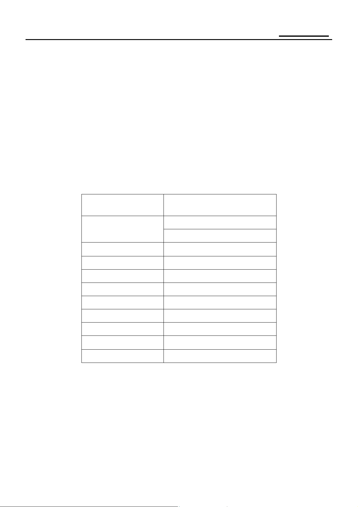
Chart of AL1922r
Panel
Signal Interface
Sync Type
Color Temp User Adjust
DDC
AU 19" V5 PANEL (For AU panel)
LTM190EX-L01 (For SEC panel)
D-SUB
DVI
Separate / Compatible
Support
DDC2B
Speaker
Headphone Jack
Microphone Jack
USB Hub
Tilt / Swivel
Height Adjust
1W + 1W (Rated power)
No
No
Not support
Yes
Yes
7
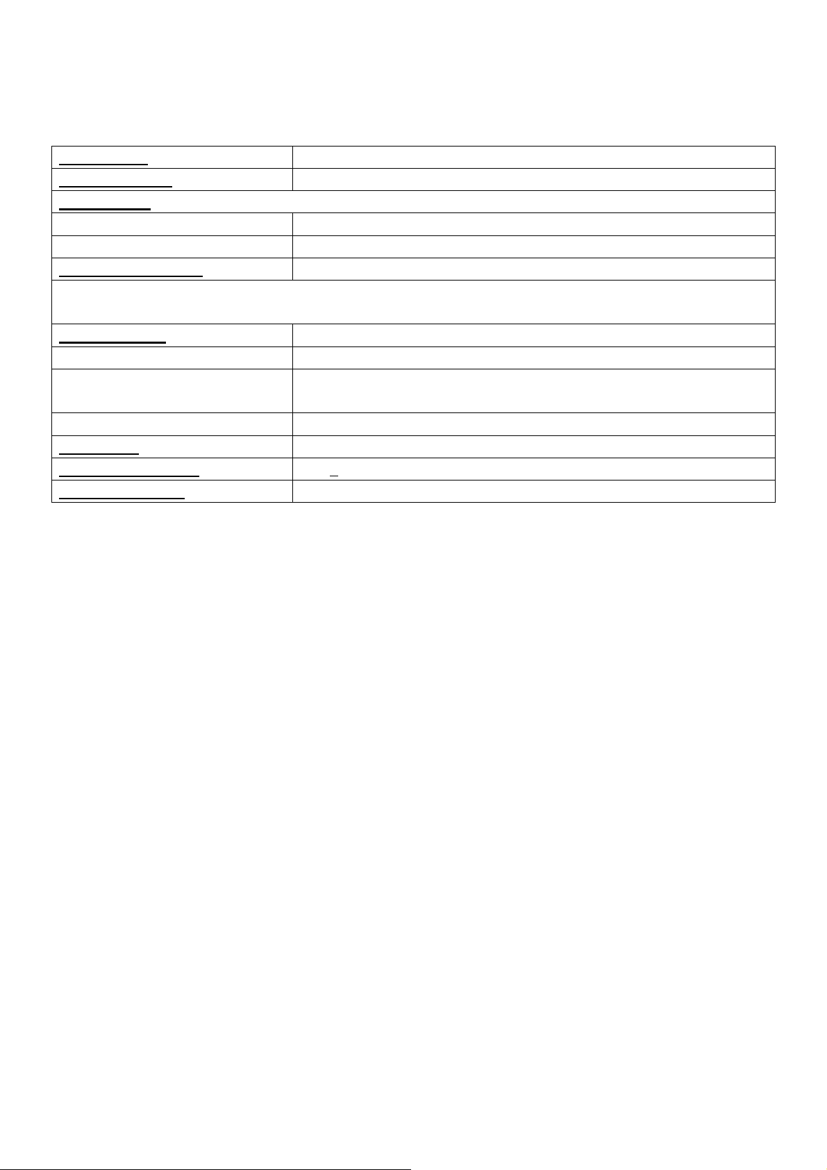
Electrical Requirements
Standard Test Conditions
All tests shall be performed under the following conditions, unless otherwise specified.
Ambient light
Viewing distance
Warm up time
All specifications >30 minutes
Fully functional 5 seconds
Measuring equipment
Control settings
User brightness control Set to Factory preset value (cut off raster)
User contrast control Set to factory preset value, which allows that the brightest two of 32 linear
Blue/white balance control In the center (unless otherwise specified)
Power input
Ambient temperature
Analog input mode
Measurement systems
The units of measure stated in this document are listed below:
1 gamma = 1 nano tesla
1 tesla = 10,000 gauss
cm = in x 2.54
lb = kg x 2.2
degrees F = [°C x 1.8] + 32
degrees C = [°F - 32]/1.8
u' = 4x/(-2x + 12y + 3)
v' = 9y/(-2x + 12y + 3)
x = (27u'/4)/[(9u'/2) - 12v' + 9]
y = (3v')/[(9u'/2) - 12v' + 9]
nits = cd/(m2) = Ft-L x 3.426
lux = foot-candle x 10.76
Dark room < 1 cd/m²
40 cm for LCD performance, 20 cm for LCD failures
Chroma 7120 signal generator or equivalent, directly
Connected to the monitor under test.
Minolta CA100 photometer, or equivalent
distributed gray-scales (0~ 700mv) can be distinguished.
100 V ~ 240 V
20℃+
5℃
1280 x1024
8
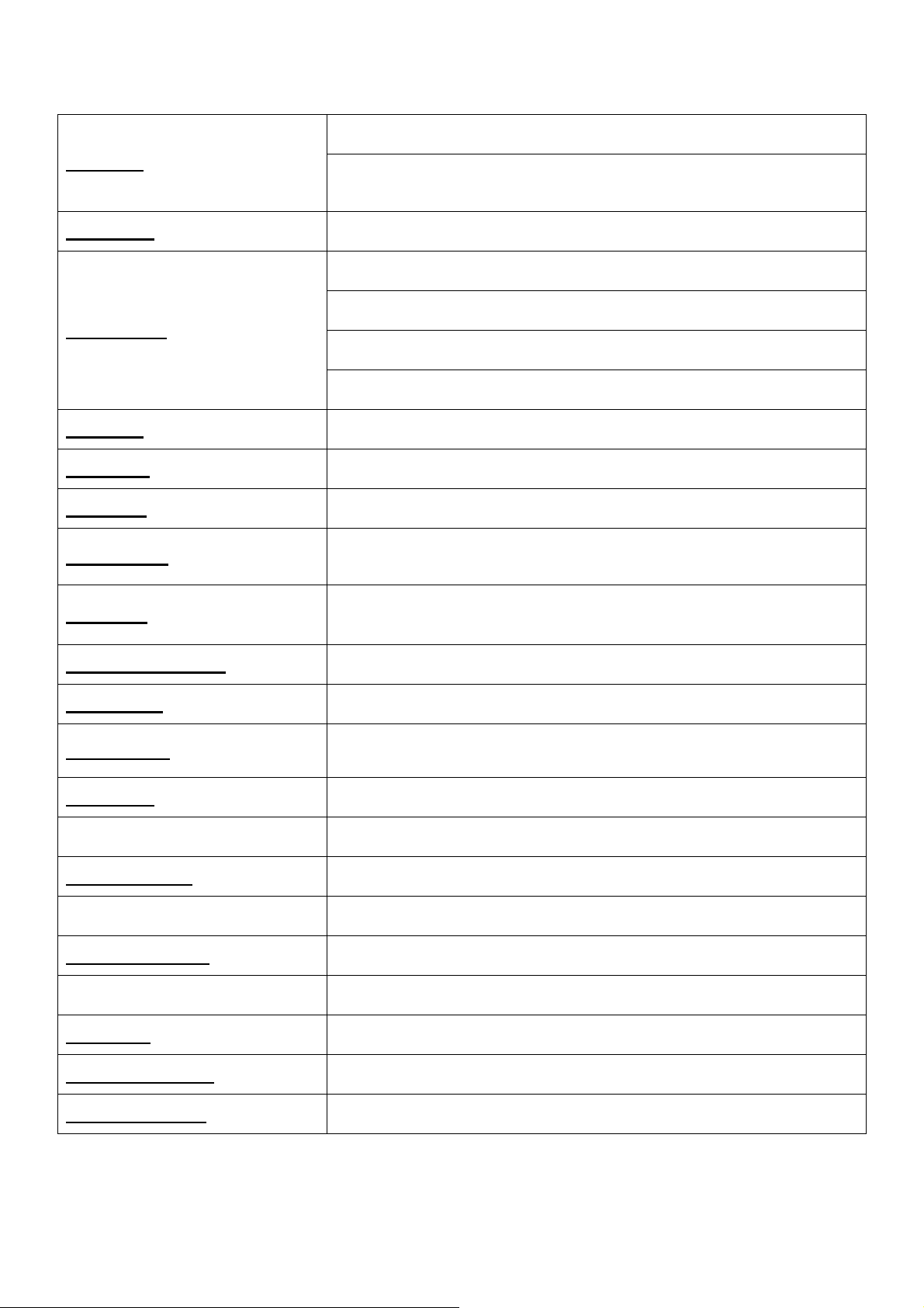
LCD Monitor General Specification
19 “ active matrix color TFT LCD
Panel type
Display size
Display mode
Pixel pitch
Display dot
Pixel clock
Contrast ratio
Brightness
19"AU V5 PANEL (For AU Panel)
LTM190EX-L01 (For SEC panel)
376.32mm (H) × 301.06mm(V)
VGA 640X480 (60/75 Hz)
SVGA 800X600 (60/75 Hz)
XGA 1024X768 (60/70/75 Hz)
SXGA 1280 × 1024 (60/75 Hz)
0.294mm(H) × 0.294mm(V)
1280 x (RGB) × 1024
135MHz
550:1(For AU Panel)
700:1(For SEC panel)
2
270 cd/m
300 cd/m
(For AU Panel)
2
(For SEC panel)
Response time (Tr/Tf)
Display color
Viewing angle
Pc interface
Signal connector
Interface frequency
Plug & play
Power Input voltage
Total output power
8ms (Typ, on/off)
16.2M(RGB 8 bit Data)
H: 140 / V: 135 (typ) (For AU Panel)
H: 150 / V: 135 (typ) (For SEC Panel)
RGB Analog Interface
Digital interface (Only Dual-Input Model)
D-Sub 15pin
DVI-D 24pin (Only Dual-Input Model)
Horizontal Frequency 30KHz ----80KHz
Vertical Frequency 55Hz ------75Hz
VESA DDC2B
47-63HZ, 100 VAC to 240VAC ±10%
60-Watt max.
9
LCD Panel Specification
LCD Panel Model (AU M190EN04 V5)
Display Type active matrix color TFT LCD
Resolution 1280x1024 pixels
Display Dot 1280x (RGB) x 1024
Display Area 376.32mm(H) x 301.06mm(V)
Pixel Pitch 0.294mm(H) x 0.294mm(V)
Display Color 16.2M (true)
Lamp Frequency 50kHz(typ)
Lamp Current 7.0 mArms (typ)
Weight 2700g (typ)
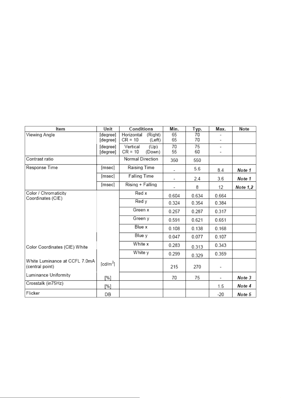
Optical Specifications
Ta = 25 ± 2°C
10
LCD Panel Model (SEC LTM190EX-L01)
Display Type active matrix color TFT LCD
Resolution 1280x1024 pixels
Display Dot 1280x (RGB) x 1024
Display Area 376.32mm(H) x 301.06mm(V)
Pixel Pitch 0.294mm(H) x 0.294mm(V)
Display Color 16.2M (true)
Lamp Frequency 60kHz(max)
Lamp Current 7.5 mArms (typ)
Weight 2250g (typ)
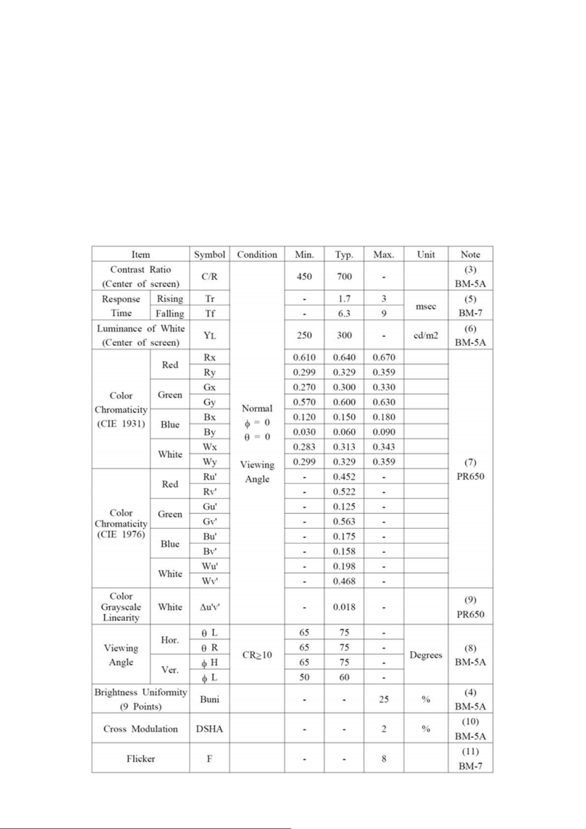
Optical Specifications
Ta = 25 ± 2°C
11
Supported Timing
Horizontal Vertical
Mode Resolution
640x480@60Hz 31.469 N 59.940 N 25.175
VGA
SVGA
XGA
1152x864@75Hz 67.5KHz P 75 P 108.000
SXGA
Horizontal Vertical
DOS 720x400@70Hz 31.469 N 70.087 P 28.322
DOS 640x350@70Hz 31.469 P 70.087 N 25.175
XGA 1024x768@72Hz 57.515 P 72.1 P 75.000
VGA 640x480@67Hz 35.000 N 66.667 N 30.240
SVGA
640x480@72Hz 37.861 N 72.809 N 31.500
640x480@75Hz 37.500 N 75.00 N 31.500
800x600@56Hz 35.156 N/P 56.250 N/P 36.000
800x600@60Hz 37.879 P 60.317 P 40.000
800x600@72Hz 48.077 P 72.188 P 50.000
800x600@75Hz 46.875 P 75.000 P 49.500
1024x768@60Hz 48.363 N 60.004 N 65.000
1024x768@70Hz 56.476 N 70.069 N 75.000
1024x768@75Hz 60.023 P 75.029 P 78.750
1280x1024@60Hz 63.981 P 60.020 P 108.000
1280x1024@75Hz 79.976 P 75.025 P 135.000
832x624@75Hz 49.725 N 74.551 N 57.2832
VESA MODES
Nominal
Frequency
+/- 0.5kHz
IBM MODES
MAC MODES
Sync
Polarity
Nominal
Freq.
+/- 1 Hz
Sync
Polarity
Nominal
Pixel
Clock
(MHz)
XGA
.
ٛ
1024x768@60Hz 48.780 N 60.001 N 64.000
1024x768@75Hz 60.241 N 74.927 N 80.000
Support Modes
There will be 20 total support modes to accommodate the above mode and other video modes within the frequency
range of the monitor.
85Hz refresh rate Support
Monitor should display 85Hz refresh rate mode as emergency mode. Monitor should
display “ Out of Range” warning menu at this mode.
12
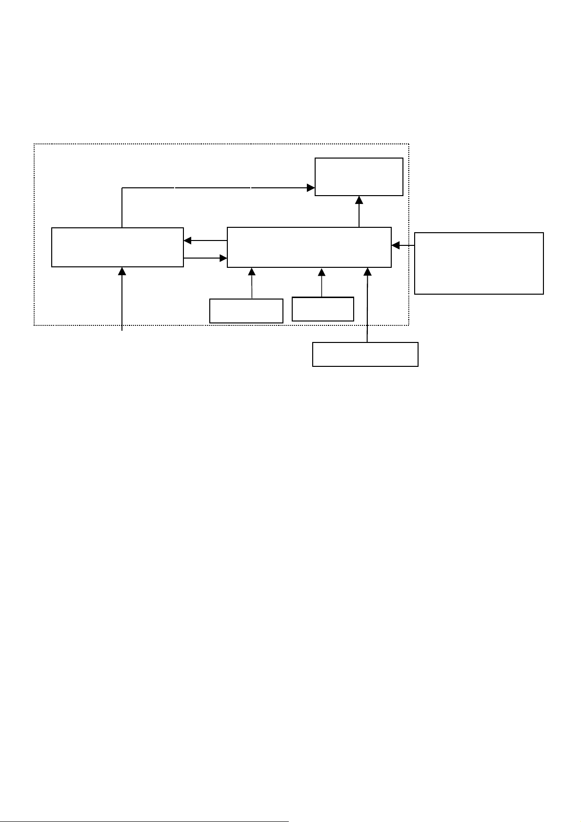
Monitor Block Diagram
The LCD MONITOR will contain a main board, a power board (include adapter and inverter), keypad board and
audio board which house the flat panel control logic, brightness control logic and DDC.
The Inverter board will drive the backlight of panel.
The adapter will provide the 12V DC-power to inverter/power board and main board..
(Inverter 、adapter Board)
Power Board
AC-IN
100V-240V
CCFL Drive.
Main Board
Audio board
Flat Panel and
CCFL
Keyboard
HOST Computer
backlight
RS232 Connector For
white balance adjustment
in factory mode
Video signal, DDC
13

Main Board Diagram
EEPROM
24C16
MCU
LCD Interface
OSD Control
Interface (Keypad)
Scaler TSU56AK LF
(Include: ADC, OSD etc)
Crystal
14.318MHZ
DVI
Connector
EEPROM
24C02
14
D-SUB
Connector
EEPROM
24C02
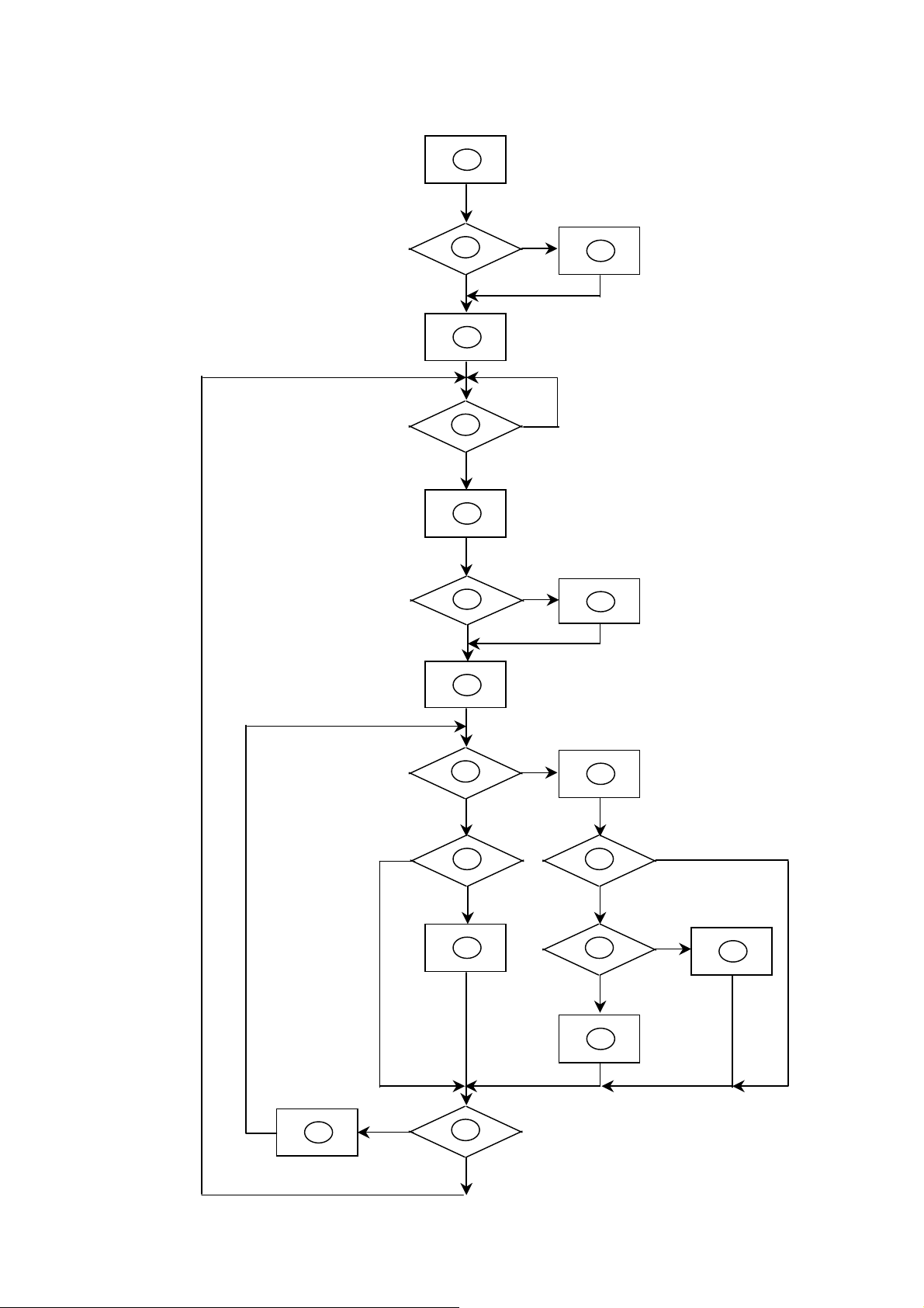
Software Flow Chart
1
Y
2
3
N
4
5
N
Y
6
N
7
8
Y
9
10
N
11
Y
N
12
13
N
Y
Y
N
14
15
16
Y
17
18
N
19
Y
15

Remark:
1) MCU initializes.
2) Is the EEPROM blank?
3) Program the EEPROM by default values.
4) Get the PWM value of brightness from EEPROM.
5) Is the power key pressed?
6) Clear all global flags.
7) Are the AUTO and SELECT keys pressed?
8) Enter factory mode.
9) Save the power key status into EEPROM.
Turn on the LED and set it to green color.
Scalar initializes.
10) In standby mode?
11) Update the lifetime of back light.
12) Check the analog port, are there any signals coming?
13) Does the scalar send out an interrupt request?
14) Wake up the scalar.
15) Are there any signals coming from analog port?
16) Display "No connection Check Signal Cable" message. And go into standby mode after the
message disappears.
17) Program the scalar to be able to show the coming mode.
18) Process the OSD display.
19) Read the keyboard. Is the power key pressed?
16
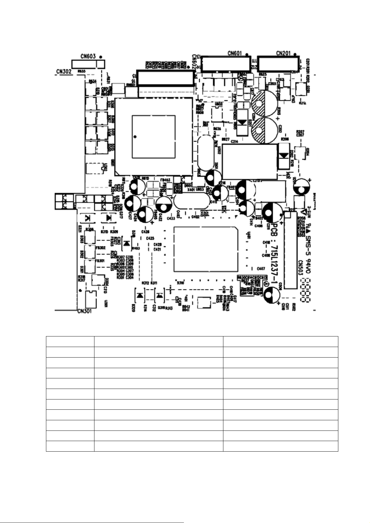
Main Board Layout
LABEL PART NO. DESCRIPTION
U201 56G 563 31 AI1117D-1.8-EI
U202 56G 563 7 AIC1084-33PM
U401 56G 562 82 TSU56AK-LF
U601 56L1125137SZ7 W78E65-40
CN201 33G8027 12 WAFER 2*6P 2.0MM R/A
CN301 88G 35315F HS D-SUB 15PIN
CN302 88G 35424F HS DVI CONN 24P
CN503 33G802724B H WAFER
X401 93G 22 53 CRYSTAL 14.318MHZ
X601 93G 22 55 H 20MHZ
17
 Loading...