

Acer ACERPOWER 6500 Annexe 1

& K DSWHU
System Board
This high-performance system board is built on an ATX baseboard
utilizing an Intel Pentium II processor running at 233/66, 266/66, and
300/66 MHz. It has two ISA, four PCI, and one AGP slots (with one
PCI- and ISA-shared slot) for future expansion. The onboard three
DIMMs sockets allow m emory upgrade to a maxim um of 384 MB and
supports both SDRAM and EDO DRAM memory.
It also supports the USB (Universal Serial Bus) connector, and other
standard features such as two UART NS16C550 serial ports, one
enhanced parallel port with Enhanced Parallel Port (EPP)/Extended
Capabilities Port (ECP) feature, a diskette drive interface, and an
embedded hard disk interface. The system has an optional IrDA
(Infrared Data Association) interf ace for remote control function. The
board also include a built-in 10/100 Mb/s Intel 82558 LAN chip that
supports Wake-On-LAN (WOL).
The system supports the power-managem ent function that conforms
to the power-saving standards of the U.S. Environmental Protection
Agency (EPA) Energy Star program. It also off ers the Plug-and-Play
feature. This feature saves the user from configuration troubles, thus
making the system more user-friendly.
The system is fully compatible with MS-DOS V6.X, OS/2, UNIX,
Windows NT and Windows 95 operating systems.
System Board 1-1

1.1 Features
The system board has the following features and components:
Intel Pentium II CPU processor (233/66, 266/66, and 300/66
•
MHz.)
384-MB maximum system memory
•
Three DIMM sockets that accept 8-, 16-, 32-, 64- and 128-MB
•
DIMMs
256-KB or 512-KB pipelined-burst second-level cache built-in
•
Pentium II CPU
Integrates an enhanced PCI local bus IDE controller
•
Intel 440LX chipset supports AGP (Accelerated Graphics Port)
•
and Ultra DMA/33 functions
256KB Flash ROM for system BIOS
•
Two ISA, four PCI, and one AGP expansion slots ( one PCI- and
•
ISA-shared slot)
Dual NS16C550 buffered serial ports and one SPP/ECP/EPP
•
parallel port
Intel 82558 LAN chip, supports WOL.
•
USB interface that enables the system to support more
•
peripherals
IrDA Interface supported (optional)
•
PS/2 mouse and keyboard interface
•
Power-management function
•
1-2 User’s Guide
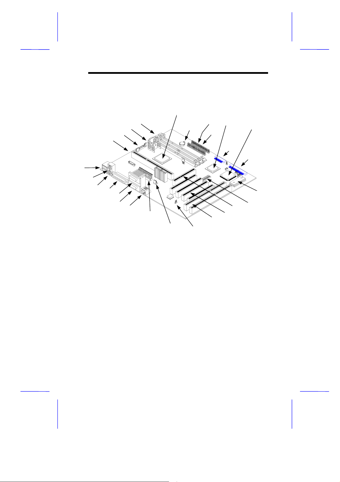
1.2 System Board Layout
Figure 1-1 shows the board layout and the locations of the important
components.
4
3
2
1
27
26
25
24
23
22
21
20
1 CPU port 15 AGP slots
2 Fan connector 1,2, and 3 16 PCI slots
3 Voltage Regulator with Heatsink 17 ISA slots
4 DIMM sockets 18 Wake on LAN (WOL) connector
5 System Chipset FX82443LX 19 Standby Power connector
6 RTC battery 20 Power Connector
7 IDE 2 connector 21 LAN Connector
8 IDE 1 connector 22 COM 1 port
9 System Chipset PIIX4 82371AB 23 COM 2 port
10 Multifunction connector 24 Parallel port
11 System Chipset FDC37C935 25 PS/2 keyboard connector
12 Floppy connector 26 PS/2 mouse connector
13 System BIOS Chip 27 USB ports
14 Core/Bus Clock switch
19
5
9
18
7
8
1210
15
16
17
6
11
12
13
14
Figure 1-1 System Board Layout
System Board 1-3

The heatsink becomes very hot when the
system is on. NEVER touch the heatsink with
any metal or with your hands.
1.3 ESD Precautions
Electrostatic discharge (ESD) can damage your processor, disk drives,
expansion boards, and other components. Always observe the
following precautions before you install a system component.
1.
Do not remove a component from its protective packaging until
you are ready to install it.
2.
Wear a wrist grounding strap and attach it to a metal par t of the
system unit before handling components. If a wrist strap is not
available, maintain contact with the system unit throughout any
procedure requiring ESD protection.
1-4 User’s Guide
1.4 Pre-installation Instructions
Always observe the following before you install a system component:
1.
Turn off the system power and all the peripher als connec ted to the
unit before opening it.
2.
Open the system according to the instructions in the housing
installation manual.
3.
Follow the ESD precautions in section 1.3 before handling a
system component.
4.
Remove any expansion boards or peripherals that block acces s to
the DIMM sockets or CPU socket.
5.
See the following sections for specific instructions on the
component you wish to install.
Do not attempt the procedures described in
the following sections unless you are a
qualified service technician.
System Board 1-5

1.5 Pentium II Processor
The board supports the Pentium II processor - a module that consists
of a Pentium Pro technology-based CPU and a second-level cache. It
utilizes the new enclosed packaging technology called S.E.C ( singleedge contact) cartridge, that allows the second-level cac he to remain
tightly coupled to the processor. It is capable of increasing the
performance of 32-bit software and multimedia applications
The Pentium II processor also supports the following features:
64-bit Pentium Pro technology-based CPU running a 233 or 266
•
MHz
MMX technology support for multimedia functions
•
32-KB internal cache size
•
256-/512-KB write-back second-level cache size
•
Non-blocking architecture to prevent CPU stalls during cache,
•
memory and I/O accesses
1-6 User’s Guide
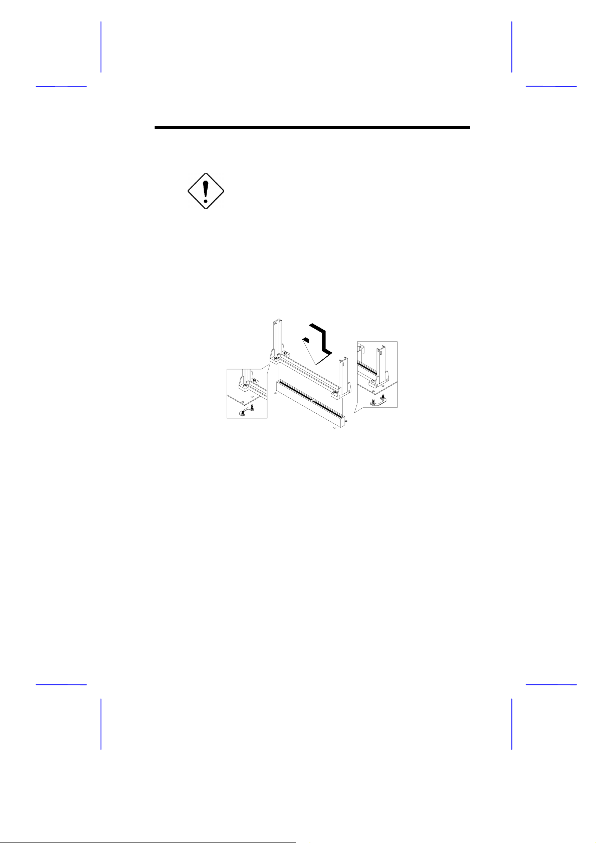
1.5.1 Installing a Pentium II Processor
Observe the ESD precautions when installing
or removing a system component.
Follow these steps to install a Pentium II processor:
1. Place the retention mechanism over the CPU connector on the
system board. Secure it with the screws that came with the
package.
Figure 1-2 Installing the Retention Mechanism
2. Remove the Pentium II proces sor from its protective pack aging.
Make sure that the latches on the sides of the module are not
pressed.
3. With the proc essor card golden fingers pointing downward, align
the processor to the posts of the retention mechanism.
4. Lower the processor into to the CPU connector on the system
board until the golden fingers touch the connector.
System Board 1-7
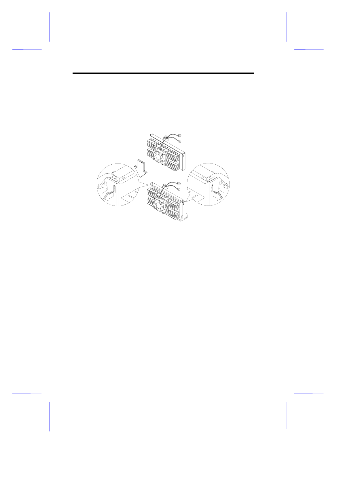
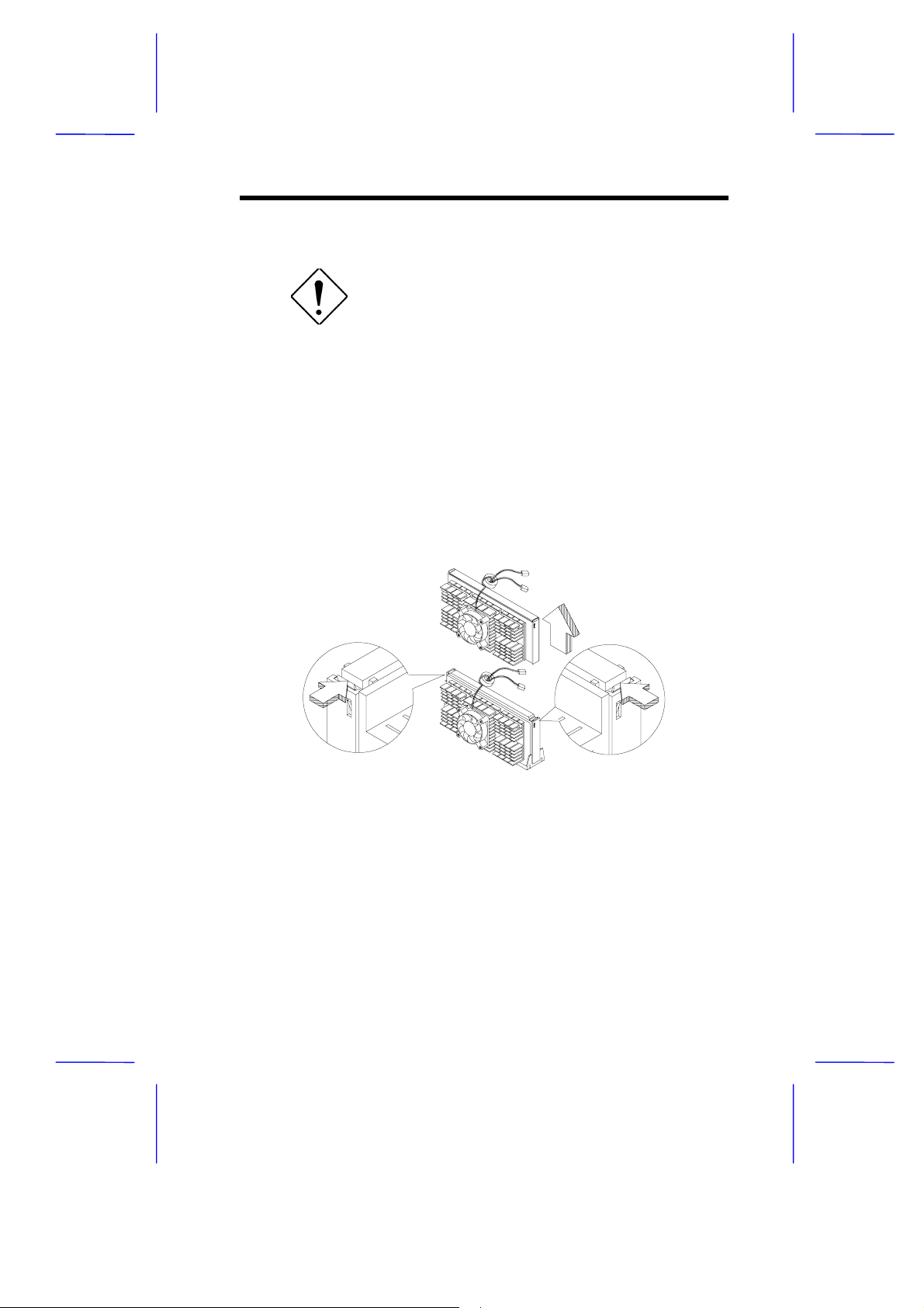
5. Press down the processor until the golden fingers completely fit
into the connector and the latches on the sides lock the process or
into place.
Figure 1-3 Installing a Pentium II Processor
1-8 User’s Guide
1.5.2 Removing a Pentium II Processor
Observe the ESD precautions when installing
or removing a system component.
Follow these steps to remove the Pentium II processor:
1. Press the latches on both sides of the processor to release it from
the retention mechanism . You will hear a click sound once the
latch is released.
2. Pull the processor to totally detach it from the CPU connector.
Figure 1-4 Removing a Pentium II Processor
System Board 1-9
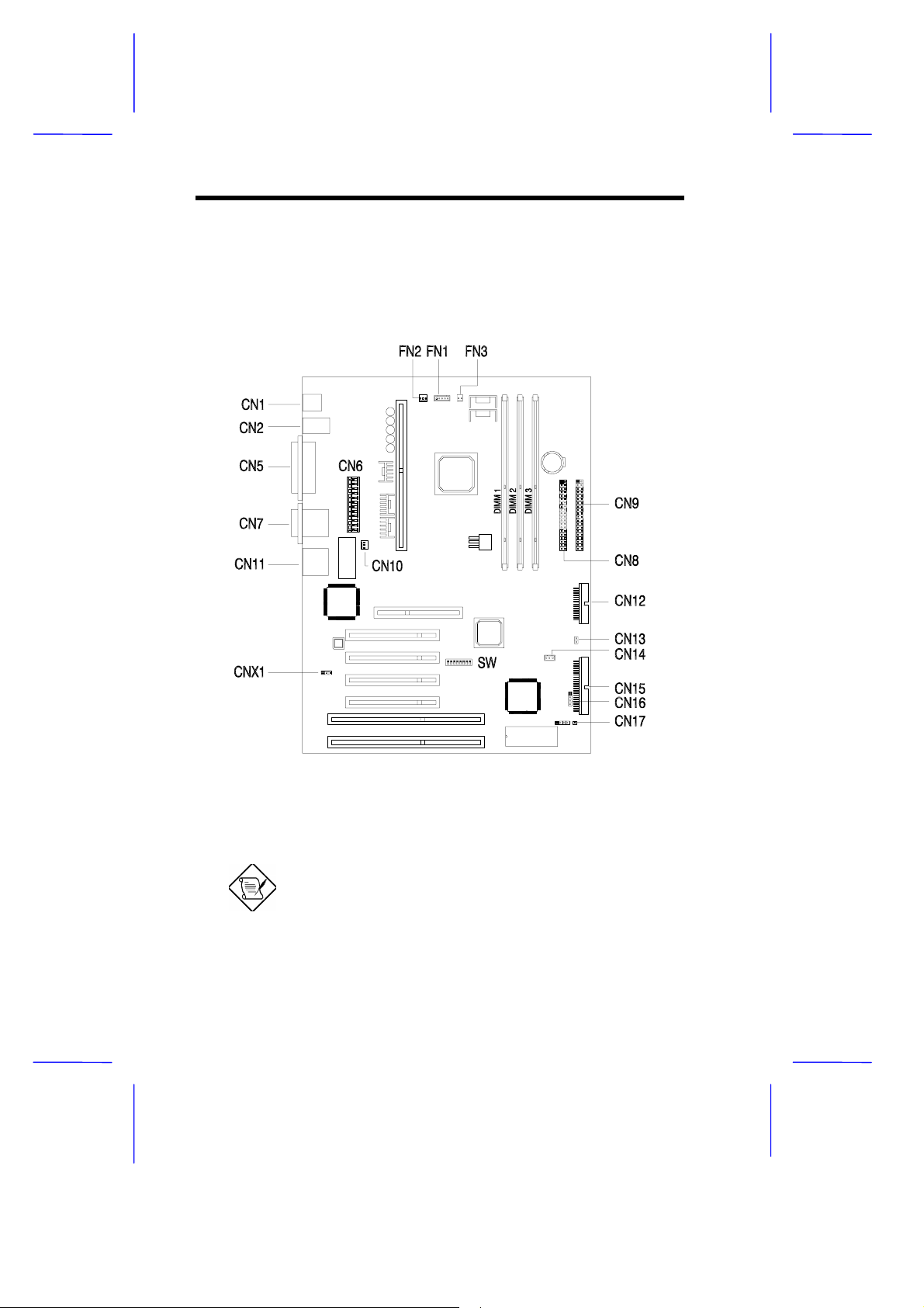
1.6 Jumpers and Connectors
Figure 1-5 shows the jumper and connector locations.
Figure 1-5 Jumper and Connector Locations
The shaded pin indicates pin 1.
1-10 User’s Guide
 Loading...