

Abit KX7-333R User Manual

Copyright and Warranty Notice
The information in this document is subject to change without notice and does not
represent a commitment on part of the vendor, who assumes no liability or responsibility
for any errors that may appear in this manual.
No warranty or representation, either expressed or implied, is made with respect to the
quality, accuracy or fitness for any particular part of this document. In no event shall the
manufacturer be liable for direct, indirect, special, incidental or consequential damages
arising from any defect or error in this manual or product.
Product names appearing in this manual are for identification purpose only and
trademarks and product names or brand names appearing in this document are the
property of their respective owners.
This document contains materials protected under International Copyright Laws. All
rights reserved. No part of this manual may be reproduced, transmitted or transcribed
without the expressed written permission of the manufacturer and authors of this manual.
If you do not properly set the motherboard settings, causing the motherboard to
malfunction or fail, we cannot guarantee any responsibility.


KX7-333/KX7-333R Motherboard User’s Manual
Index
CHAPTER 1.
1-1. F
1-2. S
1-3. I
1-4. L
CHAPTER 2.
2-1. I
2-2. I
2-3. I
2-4. C
CHAPTER 3.
3-1. CPU S
3-2. S
3-3. A
3-4. A
3-5. I
3-6. P
3-7. PNP/PCI C
3-8. PC H
3-9. L
3-10. L
3-11. S
3-12. S
3-13. E
CHAPTER 4.
4-1. T
4-2. RAID SETUP
4-3. T
EATURES OF
PECIFICATION S
TEM CHECKLIS T
AYOUT DIAGRAM FOR
NSTALLATION OF THE
NSTALLING THE MOTHERBOARD TO THE CHASSIS
NSTALLING SYSTEM MEMORY
ONNECTORS
TANDARD
DVANCED
DVANCED CHIPSET FEATURES SETUP MENU
NTEGRATED PERIPHERALS
OWER MANAGEMENT SETUP MENU
OAD FAIL-SAFE DEFAULTS
OAD OPTIMIZED DEFAULTS
ET PASSWORD
AVE
XIT WITHOUT SAVING
HE FEATURES OF
BIOS S
HE
INTRODUCTION OF KX7-333/KX7-333R FEATURES .1-1
KX7-333/KX7-333R M
....................................................................................................1-2
..................................................................................................1-3
KX7-333/KX7-333R......................................................1-4
OTHERBOARD
............................................1-1
INSTALLING THE MOTHERBOARD.............................. 2-1
AMD A
THLON™
.............................................................................2-6
, H
EADERS AND SWITCHES
INTRODUCING THE BIOS ................................................3-1
[SOFT MENU
ETUP
CMOS F
BIOS F
ONFIGURATIONS SETUP MENU
EALTH STATUS
...................................................................................................3-36
& E
XIT SETUP
™
III].........................................................................3-3
EATURES SETUP MENU
EATURES SETUP MENU
.................................................................................3-21
...........................................................................................3-34
...............................................................................3-35
..............................................................................3-35
...........................................................................................3-36
......................................................................................3-36
XP, A
THLON™ AND DURON™
................................................2-5
...............................................................2-7
.........................................................3-6
...........................................................3-9
.....................................................3-13
..................................................................3-25
...........................................................3-31
CPU .........2-2
RAID SETTING GUIDE ...................................................... 4-1
RAID
KX7-333R .......................................................................4-1
ON THE
ETTING MENU
KX7-333R ........................................................ 4-1
ON THE
...................................................................................4-2
CHAPTER 5.
5-1. DOS®...................................................................................................................5-1
5-2. W
5-3. W
CHAPTER 6.
APPENDIX A. VIA 4 IN 1 DRIVERS INSTALLATION FOR WINDOWS® 98
HPT 372 DRIVER INSTALLATION ..................................5-1
INDOWS®
INDOWS®
98 SE ................................................................................................ 5-1
2000.................................................................................................. 5-3
HPT 372 RAID MANAGEMENT SOFTWARE
INSTALLATION GUIDE FOR WINDOWS
SE & WINDOWS
®
2000 ........................................................ A-1
®
2000 ........... 6-1
APPENDIX B. INSTALLING THE HARDWARE MONITOR SYSTEM ... B-1
4200-0292-02 Rev. 1.01

APPENDIX C. BIOS UPDATE GUIDE ........................................................ C-1
APPENDIX D. TROUBLESHOOTING (NEED ASSISTANCE?) ............... D-1
APPENDIX E. HOW TO GET TECHNICAL SUPPORT ............................. E-1
KX7-333/KX7-333R

Introduction of KX7-333/KX7-333R Features
1-1
Chapter 1. Introduction of KX7-333/KX7-333R
Features
1-1. Features of KX7-333/KX7-333R Motherboard
This motherboard is designed for AMD Socket A Athlon™ XP, Athlon™ and Duron™ processors. It
supports the AMD Socket-A structure, with up to 3 GB (Unbuffered) or 3.5 GB (Registered) of memory,
super I/O and Green PC functions.
The KX7-333/KX7-333R uses the VIA KT333 and VT8233A chipsets to make the evolutionary move
from PC 100/PC 133 SDRAM to PC 1600/PC 2100/PC 2700 DDR SDRAM, increasing the speed of the
system and memory buses from 100 MHz to 166 MHz. Its 200/266/333 MHz memory interface supports
a wide range of PC 1600/PC 2100/PC 2700 DDR SDRAM memory devices now on the market.
VIA KT333 is a system bus controller, or northbridge, that houses the high-speed system elements critical
to overall system performance while also containing the system interface to the processor. The key
functions of the KT333 System Controller include the 266 MHz Athlon System Bus, the 333 MHz DDR
Memory Subsystem, the AGP 4X/2X/1X modes Graphics Interface (AGP 2.0 Compliant) and the 33
MHz/32-bit PCI Bus Interface (PCI 2.2 Compliant), including arbiter.
DDR SDRAM is the newest memory standard, it provides the maximum translation bandwith and also
greatly improves data transaction delays. This feature improves whole system performance and speed,
especially multimedia environment applications.
The KX7-333/KX7-333R has a built in Ultra DMA 133 function. This means that it provides speedier
HDD throughput boosting overall system performance. Ultra DMA 133 is the newest standard for IDE
devices. It enhances existing Ultra DMA 33 technology by increasing both performance and data integrity.
This new high-speed interface almost double the Ultra DMA 66 burst data transfer rate to 133 Mbytes/sec.
The result is maximum disc performance using the current PCI local bus environment. Another benefit is
you can connect four IDE devices in your system through either Ultra DMA 66, Ultra DMA 100 or Ultra
DMA 133. You will have more flexibility to expand your computer system.
KX7-333R’s built-in HighPoint HPT 372 chipset gives you the capability to support Ultra DMA 133.
Ultra DMA 133 is the newest standard for IDE devices. It provides two IDE channels (IDE3, IDE4) that
also support Ultra DMA 133 specifications, and it allows for four additional IDE devices in your
computer system. It can give you high performance and efficiency data transfer rate through the IDE
channels. This also means that your computer, in total, can connect up to eight IDE devices (IDE1 ~
IDE4). This allows for maximum expandability for future hardware demands. This chipset also supports
IDE RAID, inlcuding RAID 0, RAID 1 and RAID 0+1. This feature enables you to maximize your data
storage performance and security.
™
KX7-333/KX7-333R provides high flexibility to users building AMD Socket A Athlon
and Duron
The KX7-333/KX7-333R has built-in hardware monitoring functions (refer to Appendix B for detailed
information) to ensure a safe computing environment.
™
systems. It provides the option of 133MHz/133MHz CPU and memory bus combinations.
XP, Athlon™
User’s Manual

Chapter 1
1-2
1-2. Specifications
1. CPU
! Supports AMD Athlon™ XP 1500+ ~ 2200+ or future Socket A processors based on 200 MHz/266
MHz (100 MHz/133 MHz Double Data Rate)
! Supports AMD Athlon
MHz (100 MHz/133 MHz Double Data Rate)
! Supports AMD Duron
MHz Double Data Rate)
! Supports 200 MHz Alpha EV6 bus for the AMD Athlon
2. Chipset (VIA KT333 and VT8233A):
! Supports Ultra DMA 33, Ultra DMA 66, Ultra DMA 100 and Ultra DMA 133 IDE protocol
! Supports Advanced Configuration and Power Management Interface (ACPI)
! Accelerated Graphics Port connector supports AGP 2X (3.3V) and 4X (1.5V) mode (Sideband)
device
! Supports 200 MHz/266 MHz/333 MHz (100 MHz/133 MHz/166 MHz Double Data Rate) memory
bus settings
3. Ultra DMA 133/RAID (For KX7-333R Only)
! HighPoint HPT 372 IDE controller
! Supports Ultra DMA 133 MB/sec data transfer rate
! Supports RAID0 (Stripping mode for boosting performance) mode
! Supports RAID1 (Mirroring mode for data security) mode
! Supports RAID 0+1 (Stripping and Mirroring) mode
4. Memory (System Memory)
! Four 184-pin DIMM slots support PC 1600, PC 2100 and PC 2700 DDR SDRAM modules
! Supports 6 banks up to 3 GB DRAMs for unbuffered DDR/SDRAM modules. (64, 128, 256, 512
MB and 1 GB DDR SDRAM). For PC 2700 DDR SDRAM modules, it supports 4 banks up to 2 GB
DRAMs for unbuffered DDR/SDR modules. (64, 128, 256, 512 MB and 1 GB DDR SDRAM).
! Supports 8 banks up to 3.5 GB DRAMs for registered DDR/SDRAM modules. (64, 128, 256, 512
MB and 1 GB DDR SDRAM). For PC 2700 DDR SDRAM modules, it supports 6 banks up to 3 GB
DRAMs for registered DDR/SDRAM modules. (64, 128, 256, 512 MB and 1 GB DDR SDRAM).
5. System BIOS
! SOFT MENU™ III technology, can easily set the processor parameters
! Award PnP (Plug and Play) BIOS supports APM and DMI (Desktop Management Interface)
! Supports ACPI (Advanced Configuration Power Interface)
! Write-Protect Anti-Virus function by AWARD BIOS
6. Multi I/O Functions
! Two channels of Bus Master IDE ports supporting up to four Ultra DMA 33/66/100/133 devices
(KX7-333 Only). And two channels (IDE3 & IDE4) of Bus Master IDE ports supporting up to four
Ultra DMA 33/66/100/133 specifications HDD devices (KX7-333R Only)
! One floppy port connector (up to 2.88MB)
! One PS/2 keyboard and PS/2 mouse connectors
™
700 MHz ~ 1.4 GHz or future Socket A processors based on 200 MHz/266
™
600 MHz ~ 1.2 GHz or future Socket A processors based on 200 MHz (100
™
XP, Athlon™ and Duron™ processors
KX7-333/KX7-333R
Introduction of KX7-333/KX7-333R Features
! Two USB connectors
! Two serial ports connectors
! One parallel port connector (Standard/EPP/ECP)
1-3
7. Miscellaneous
! ATX form factor
! One AGP slot, six PCI slots
! Built-in Wake on LAN header
! Built-in IrDA TX/RX header
! Built-in Wake On Ring header
! One USB header for two extra USB channels
! Hardware monitoring:Included fan speed, voltages, CPU and system environment temperature
! Board size: 305 * 245mm
# Supports Wake On LAN, Modem, but your ATX power supply 5V standby power must be
able to provide at least a 720mA current capacity. Otherwise, the functions may not work
normally.
# PCI slot 5 shares IRQ signals with the HPT 372 IDE controller (supports Ultra DMA 133). The
driver for HPT 372 IDE controller supports IRQ sharing with other PCI devices. But if you
install a PCI card that doesn’t allow IRQ sharing with other devices into PCI slot 5, you may
encounter some problems. Furthermore, if your Operating System doesn’t allow peripheral
devices to share IRQ signals with each other, such as Windows
install a PCI card into PCI slot 5. (KX7-333R Only)
# HPT 372 IDE controller is designed to support high-speed and high performance mass storage
devices. Thus we suggest that you don’t connect non-disk devices that use ATA/ATAPI
interfaces, such as CD-ROM to HPT 372 IDE connector (IDE3 & IDE4). (KX7-333R Only)
# This motherboard supports the standard bus speeds of 66 MHz/100 MHz/133 MHz that are
used by specific PCI, processor and chipset specifications. Exceeding these standard bus speeds
is not guaranteed due to the specific component specifications.
# Specifications and information contained in this manual are subject to change without notice.
®
NT for example, you can’t
Note
All brand names and trademarks are the property of their respective owners.
1-3. Item Checklist
Check that your package is complete. If you discover any damaged or missing items, please contact your
retailer or dealer.
$ One ABIT KX7-333 or one KX7-333R motherboard
$ One 80-wire/40-pin ribbon cable for master and slave Ultra DMA 133, Ultra DMA 100, Ultra DMA
66 or Ultra DMA 33 IDE devices (KX7-333 Only)
$ Two 80-wire/40-pin ribbon cable for master and slave Ultra DMA 133, Ultra DMA 100, Ultra DMA
66 or Ultra DMA 33 IDE devices (KX7-333R Only)
User’s Manual
Chapter 1
1-4
$ One ribbon cable for 3.5” floppy disk devices
$ One compact disc for support drivers and utilities
$ One USB cable with bracket
$ One user’s manual for the motherboard
$ One floppy disk of HPT 372 drivers (KX7-333R Only)
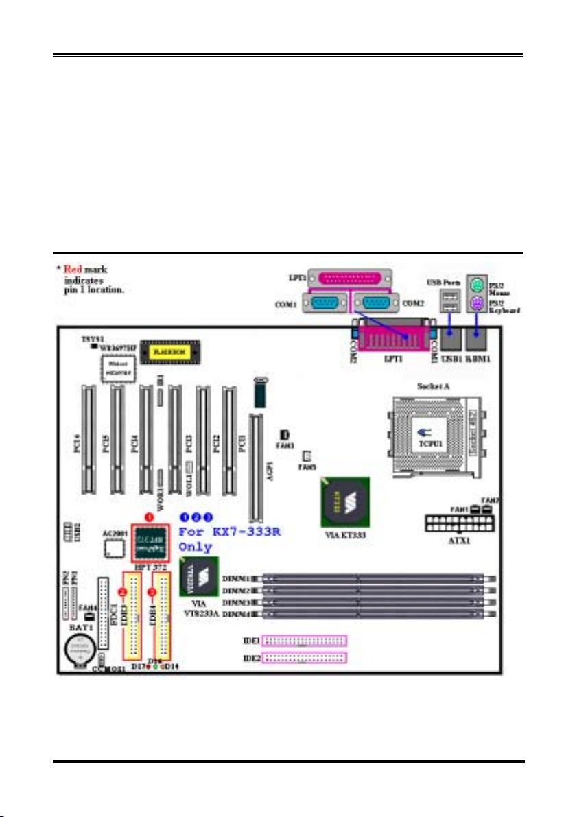
1-4. Layout Diagram for KX7-333/KX7-333R
Figure 1-1. KX7-333/KX7-333R motherboard component location
KX7-333/KX7-333R
Installing the Motherboard
2-1
Chapter 2. Installing the Motherboard
This KX7-333/KX7-333R motherboard not only provides all standard equipment for classic personal
computers, but also provides great flexibility for meeting future upgrade demands. This chapter will
introduce step by step all of the standard equipment and will also present, as completely as possible,
future upgrade capabilities. This motherboard is able to supports all AMD Socket A Athlon
™
and Duron™ processors now on the market. (For details, see specifications in Chapter 1.)
Athlon
This chapter is organized according the following features:
Installation of the AMD Socket A Athlon™ XP, Athlon™ and Duron™ CPU
1.
Installing the Motherboard to the Chassis
2.
Installing System Memory
3.
Connectors, Headers and Switches
4.
™
XP,
%%%%
Before you install or unplug any connectors or add-on cards, please remember to turn the ATX power
supply switch off (fully turn the +5V standby power off), or take the power cord off. Otherwise, you may
cause the motherboard components or add-on cards to malfunction or be damaged.
&
Please read our instructions carefully and follow them step-by-step. Our objective is to enable the novice
computer user to perform the installation by himself. We have attempted to write this document in a very
clear, concise and descriptive manner to help overcome any obstacles you may face during installation.
This chapter contains many color drawings, diagrams and photos, we strongly recommend you read this
chapter use the PDF file that is stored on the CD-Title. Color improves the clarity and quality of the
diagrams. For the downloadable edition, as files larger than 3 MB are difficult to download, we will cut
the graphics and photo resolution to reduce the manual file size. In such this case, if your manual is
downloaded from our WEB site and not from a CD-ROM, enlarging graphics or photos will distort the
image.
Before Proceeding with the Installation
User Friendly Instructions
Diagram and Photos
%%%%
User’s Manual
Chapter 2
2-2
2-1. Installation of the AMD Athlon™ XP, Athlon™ and Duron™
CPU
Note
! Installing a heatsink and cooling fan is necessary for heat to dissipate from your processor. Failing
to install these items may result in overheating and processor damage.
! The AMD Socket A processor will produce a lot of heat while operating, so you need to use a large
heat sink that is especially designed for the AMD socket A processor. Otherwise, it may result in
overheating and processor damage.
! If your processor fan and its power cable are not installed properly, never plug the ATX power
cable into the motherboard. This can prevent possible processor damage.
! Please refer to your processor installation manual or other documentation with your processor for
detailed installation instructions.
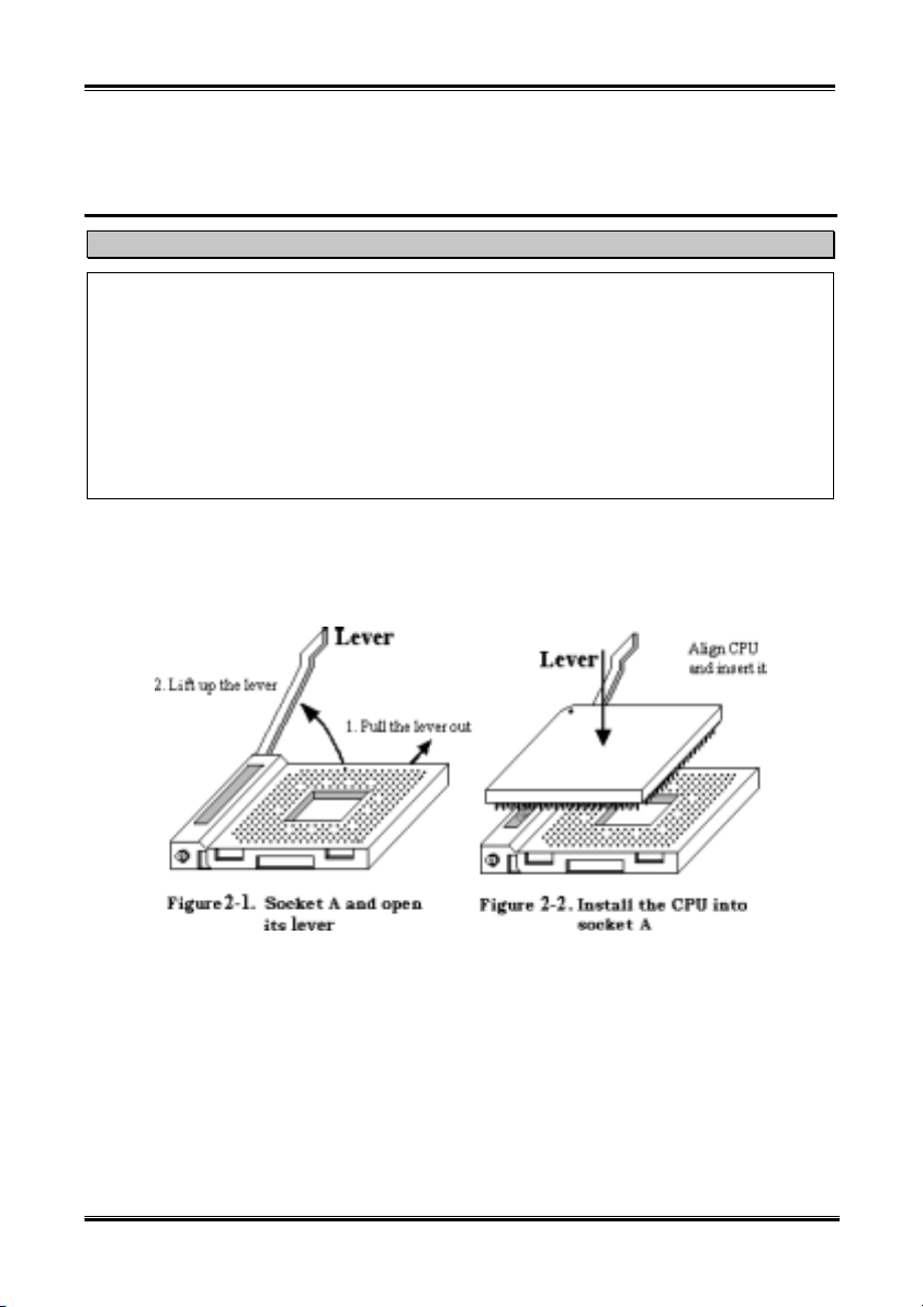
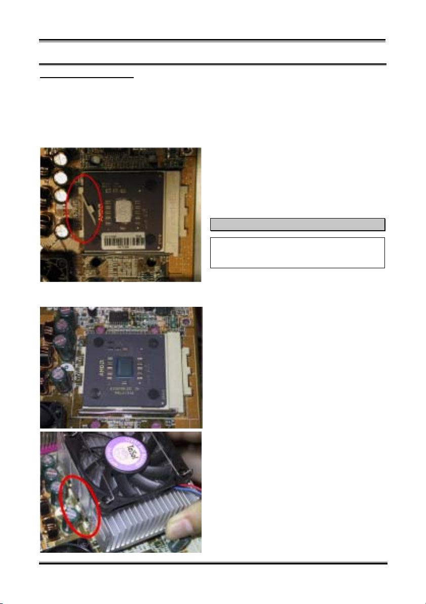
The AMD Socket A Athlon™ XP, Athlon™ and Duron™ processor installation is easy, like Socket 7
®
Pentium
easily fix the processor firmly into position. Figure 2-1 shows you what the socket A looks like, and how
to open the lever. The socket A has more pins than the socket 7. Therefore, a Pentium
cannot be inserted into a socket A.
processors before. Because it uses the “Socket A” ZIF (Zero Insertion Force) socket, you can
®
level processor
When you raise the lever, you have to loosen the socket lock. Please raise the lever to the end, and
prepare to insert the processor. Next, you need to align the processor pin 1 to the socket pin 1. If you put
it in the wrong direction, you will not be able to insert the processor easily, and processor pins will not
fully go into the socket. If this is the case, please change the direction, until it easily and fully inserts into
the socket A. See Figure 2-2. At the same time check the processor temperature detection thermistor
height (if your motherboard has this component), then you can slowly insert the processor into the Scoket
A. Finally, you need to check that the processor edge and the Socket A edge is parallel. It should be
parallel and not tilted.
When you finish the above, push the lever down to its original position, you should feel the lever lock the
socket A. You have then finished the processor installation.
KX7-333/KX7-333R
Installing the Motherboard
Heatsink Installation Hints
Because the processor will produce a lot of heat while operating, we suggest you use a heatsink approved
by AMD to be safe and to keep the processor temperature within normal operation temperatures. The
heatsink will be large and heavy, so the fixing plate has a strong tension. When you install the heatsink on
to the processor and its socket, you have to very carefully fix the fixing plate to the processor socket hook
on both sides. If you do not pay attention to this, you may make the fixing plate scratch the PCB surface
and cause circuit damage, break socket hooks or damage the die on the top of processor.
Please follow the sequence metioned below, Do Not
inverse the sequence. Otherwise, you may have a
situation like the photo on the left. Because of the
design of the CPU socket, the left side hooks are not
as strong as the right side hooks. If you follow our
suggestions you will prevent your processor and
socket from damage.
Note
Considering the chassis structure problem, please
always take off the motherboard from chassis,
before adding or removing a heatsink kit.
The proper procedure to install the heatsink kit:
First, install the processor into the processor socket.
Insert the heatsink left side fix plate into the
processor socket left side fix hooks. Make sure the fit
is very tight. Check the photo on the left.
2-3
User’s Manual
Chapter 2
2-4
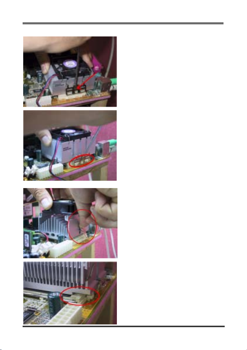
Insert a flat screwdriver into the middle slot of the
right side fix plate and push down. Then you can
push the fix plate over the socket hooks on the right
side. Check the photo on the left.
Check the photo on the left. You have finished the
heatsink installation.
Now hold the whole heatsink and slightly shake it,
make sure the buttom right side of the heaksink does
not contact the right side of the Socket (see bottom
picture). Otherwise, the processor die does not have
proper contact with the heatsink. This situation may
cause processor damage.
Remember to install the heatsink fan power cable to
the CPU fan header on the motherboard.
Now you can reinstall the motherboard back into the
chassis.
When all above procedures done, you can connect
the ATX power cable to the motherboard.
If you have different types of heatsink kit, please
refer to the manual that came with the heatsink kit.
The left photo shows another type of heatsink fix
plate design. The install sequences are still the same,
from right side to left side. Just remember that.
We strongly recommand you to buy a heatsink
with three holes in the fix plate. This will provide
the best stabability and won’t cause the Socket fix
hooks to be broken or damaged.
The left photo shows the bottom right side of the
heaksink in contact with the right side of the Socket.
In this situation, the processor die does not properly
contact the heatsink. If you start the computer at this
monent, it will immediately cause the processor
damage. Always check this place when you finish the
heatsink installation.
KX7-333/KX7-333R
Installing the Motherboard
2-5
2-2. Installing the Motherboard to the Chassis
After you install the processor to the motherboard, you can start to fix the motherboard into the chassis.
Most computer chassis will have a base on which there will be many mounting holes that allows the
motherboard to be securely attached and at the same time, prevents short circuits. There are two ways to
attach the motherboard to the base of chassis:
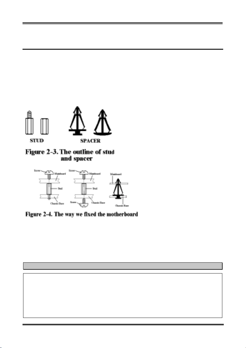
! With studs
! With spacers
Please refer to figure 2-3, which shows the studs and spacers. There may be several types, but all look
like the figures below:
In principle, the best way to attach the
motherboard is with studs. Only if you
are unable to do this should you attach the
board with spacers. Take a careful look at
the motherboard and you will see many
mounting holes on it. Line these holes up
with the mounting holes on the base. If
the holes line up and there are screw
holes this means you can attach the
motherboard with studs. If the holes line
up and there are only slots, this means
you can only attach the motherboard with
spacers. Take the tip of the spacers and
insert them into the slots. After doing this
to all the slots, you can slide the
motherboard into position aligned with
the slots. After the motherboard has been
positioned, check to make sure everything
is OK before putting the casing back on.
motherboard using studs or spacers.
Figure 2-4 shows you the way to affix the
Note
If the motherboard has mounting holes, but they don’t line up with the holes on the base and there are
no slots to attach the spacers, don’t worry, you can still attach the spacers to the mounting holes. Just
cut the bottom portion of spacers (the spacer they may be a little hard to cut, so be careful with your
hands). In this way you can still attach the motherboard to the base without worrying about short
circuits. Sometimes you may need to use the plastic springs to isolate the screw from the motherboard
PCB surface, because the circuit wire may be near by the hole. Be careful, don’t let the screw contact
any the printed circuit wire or parts on the PCB that are near the fixing hole, otherwise it may damage
the board or cause board malfunctioning.
User’s Manual
Chapter 2
2-6
2-3. Installing System Memory
This motherboard provides four 184-pin DDR DIMM sites for memory expansion. The DDR SDRAM
DIMM sockets support 8 M x 64 (64 MB), 16M x 64 (128 MB), 32 M x 64 (256 MB), 64 M x 64 (512
MB) and 128 M x 64 (1024 MB) or double density DDR SDRAM DIMM modules. Minimum memory is
64 MB and the maximum memory is 3 GB (Unbuffered, PC 1600 and PC 2100) / 2GB (Unbuffered,
PC 2700) or 3.5 GB (Registered, PC 1600 and PC 2100) / 3 GB (Registered, PC 2700) DDR SDRAM.
There are four memory module sockets on the system board (for a total of eight banks). In order to create
a memory array, following rules must be followed.
! For those modules, we suggest that you be populate DIMM1 to DIMM4 in order.
! Supports single and double density DDR DIMMS.
Table 2-1. Valid Memory Configurations
Bank Memory Module Total Memory
Bank 0, 1
(DDR DIMM1)
Bank 2, 3
(DDR DIMM2)
Bank 4, 5
(DDR DIMM3)
Bank 6, 7
(DDR DIMM4)
Total System Memory for Unbuffered DDR DIMM
(PC 1600/PC 2100)
Total System Memory for Registered DDR DIMM
(PC 1600/PC 2100)
Total System Memory for Unbuffered DDR DIMM
Total System Memory for Registered DDR DIMM
DDR DIMM sockets have minor physical differences. If your module doesn't seem to fit, please do not
force it into the socket as you may damaged your memory module or DDR DIMM socket.
The following procedure will show you how to install a DDR DIMM module into a DDR DIMM socket.
Step 1. Before you install the memory module, please place the computer power switch in the off
position and disconnect the AC power cord from your computer.
Step 2. Remove the computer’s chassis cover.
Step 3. Before touching any electronic components, make sure you first touch an unpainted, grounded
metal object to discharge any static electricity stored on your clothing or body.
Step 4. Locate your computer’s 184-pin memory expansion DDR DIMM socket.
64 MB, 128 MB, 256 MB,
512 MB, 1024 MB
64 MB, 128 MB, 256 MB,
512 MB, 1024 MB
64 MB, 128 MB, 256 MB,
512 MB, 1024 MB
64 MB, 128 MB, 256 MB,
512 MB, 1024 MB
(PC 2700)
(PC 2700)
64 MB ~ 1 GB
64 MB ~ 1 GB
64 MB ~ 1 GB
64 MB ~ 1 GB
64 MB ~ 3 GB
64 MB ~ 3.5 GB
64 MB ~ 2 GB
64 MB ~ 3 GB
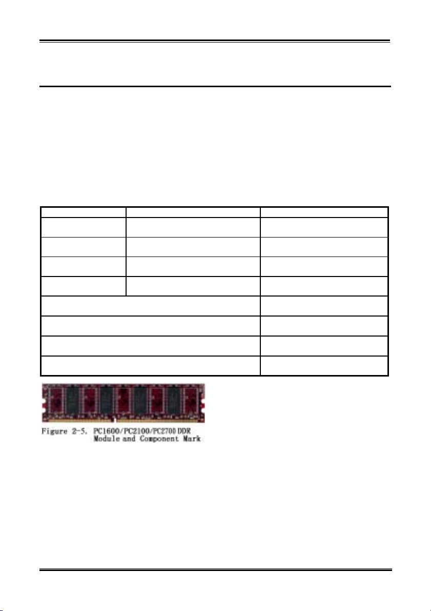
Generally, installing DDR SDRAM modules to your
motherboard is an easy thing to do. You can refer to
Figure 2-5 to see what a 184-pin PC 1600, PC 2100
and PC 2700 DDR SDRAM module looks like.
Unlike installing SIMMs, DIMMs may be
“snapped” directly into the socket. Note: Certain
KX7-333/KX7-333R
Installing the Motherboard
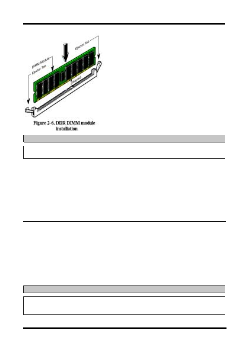
Step 5. Insert the DDR DIMM module into the expansion
socket as shown in the illustration. Note how the
module is keyed to the socket. You can refer to
Figure 2-6 for the details. This insures the DDR
DIMM module will be plugged into the socket in
one way only. Firmly press the DDR DIMM
module into DDR DIMM socket, making certain
the module is completely seated in the DDR
DIMM socket.
Step 6. Once the DDR DIMM module has been installed,
the installation is complete and the computer’s
cover can be replaced. Or you can continue to
install other devices and add-on cards that are
mentioned in the following section.
Note
When you install a DDR DIMM module fully into the DDR DIMM socket, the eject tab should be
locked into the DDR DIMM module very firmly and fit into its indention on the both sides.
It is difficult to differentiate between the PC 1600, PC 2100 and PC 2700 DDR SDRAM modules from
the exterior. The only way you can identify them is to look at the sticker on the DDR SDRAM module.
The sticker will tell you which kind of structure module the DDR SDRAM is.
2-7
2-4. Connectors, Headers and Switches
Inside the case of any computer several cables and plugs have to be connected. These cables and plugs are
usually connected one-by-one to connectors located on the motherboard. You need to carefully pay
attention to any connection orientation the cables may have and, if any, notice the position of the first pin
of the connector. In the explanations that follow, we will describe the significance of the first pin.
We will show you all of the connectors, headers and switches here, and tell you how to connect them.
Please pay attention and read the entire section for necessary information before attempting to finish all of
the hardware installation inside the computer chassis.
Figure 2-7 shows you all of the connectors and headers that we’ll discuss in the next section, you can use
this diagram to visually locate each connector and header we describe.
Note
This components diagram will be slightly different because there are a number of models. We’ll use
the KX7-333R motherboard as standard; all descriptions of connector and header will be based on the
KX7-333R motherboard.
All connectors, headers and switches mentioned here, will depend on your system configuration. Some
User’s Manual

Chapter 2
2-8
features you may (or may not) have and need to connect or configure depending on the peripheral. If your
system doesn't have such add-on cards or switches you can ignore some special feature connectors.
Figure 2-7. All connectors and headers for the KX7-333R
First, Let’s see the headers that KX7-333R uses, and what their functions are. We will show you all the
connectors and headers.
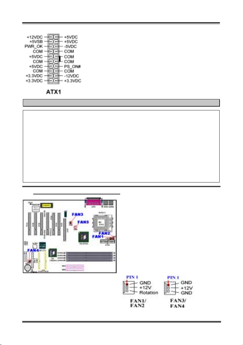
(1). ATX1: ATX Power Input Connector
KX7-333/KX7-333R
Attach the connector from the power supply to the
ATX1 connector here. Remember you have to push
the connector from the ATX power supply firmly to
the end with the ATX1 connector, insuring that you
have a good connection.
Note: Watch the pin position and the orientation.
Installing the Motherboard
Caution
If the power supply connectors are not properly attached to the ATX power supply, the power supply
or add-on cards may be damaged.
One end of AC power core connects to ATX power supply, and the other end (AC plug) will plug into
the wall outlet. Be aware that when facing the wall outlet, the round hole is in the middle. The right
side slot is called ground wire slot. It has a longer slot length than the left side slot. The left side slot is
called the live wire slot. You can use an electroscope to detect its polarity or you can use a voltage
meter to measure the voltage of both slot sides. If you insert an electroscope into the live wire slot, the
electroscope will light up. Using a voltage meter, you will find that the live wire slot will register a
higher voltage.
If you reverse the polarity of AC plug, it may affect the life of computer equipment, or cause an
electric shock when you touch the computer chassis. We suggest that you plug the computer AC plug
to a three-hole wall outlet for better safety and to avoid electric shock.
2-9
(2). FAN1, FAN2, FAN3, FAN4 & FAN5 header
Attach the connector from the processor fan to the
header named FAN1 or FAN2 (These two fan
headers have a sense signal that can detect fan
rotation speeds) and connector from the front
chassis fan to the header FAN4. Attach the
connector from the power fan or back chassis fan to
FAN3 header and attache the connector from
northbridge fan to the header named FAN5.
You must attach the CPU fan to the processor, or
your processor will work abnormally or may be
damaged by overheating. To prevent the computer
chassis internal temperature from getting too high,
also connect the chassis fan.
Note: Watch the pin position and the orientation
User’s Manual
Chapter 2
2-10
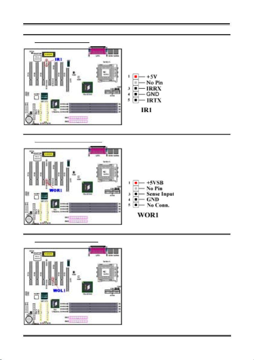
(3). IR1: IR Header (Infrared)
There is a specific orientation for pins 1 through 5,
attach the connector from the IR KIT or IR device to
the IR1 header. This motherboard supports standard
IR transfer rates.
Note: Watch the pin position and the orientation
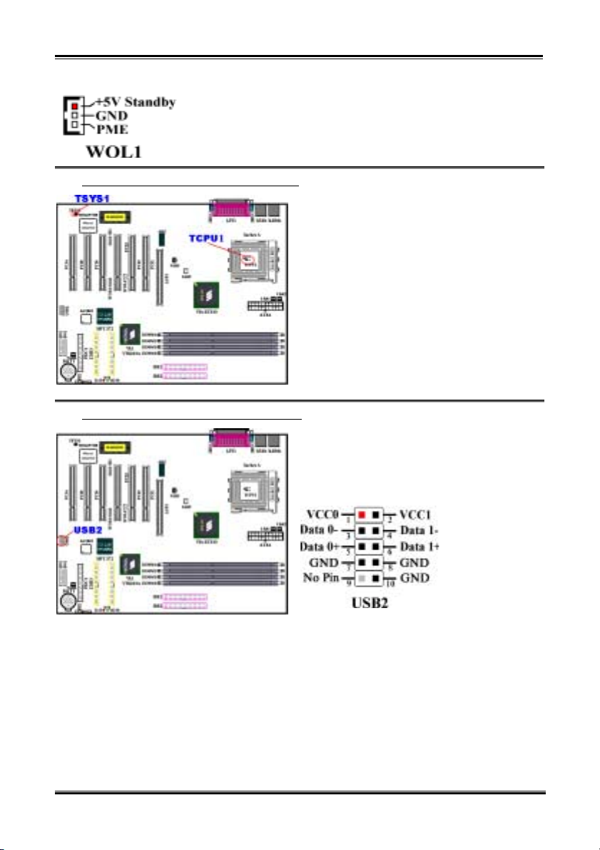
(4). WOR1: Wake On Ring Header
(5). WOL1: Wake on LAN Header
If you have an internal modem adapter that supports
this feature, then you can connect the specific cable
from the internal modem adapter to this header. This
feature lets you wake up your computer via remote
control through the modem.
Note: Watch the pin position and the orientation
If you have a network adapter that supports this
feature, then you can connect the specific cable from
the network adapter to this header. This feature lets
you wake up your computer via remote control
through a local area network. You may need a
specific utility to control the wake up event, like
using the PCnet Magic Packet utility or other similar
utilities.
There are three types of WOL, “Remote Wake-Up
high (RWU-high)”, “Remote Wake-Up low
(RWU-low)”, and “Power Management Event
(PME)”. This motherboard supports the type of
“Remote Wake-Up low (RWU-low)” only.
Note: Watch the pin position and the orientation
KX7-333/KX7-333R
Installing the Motherboard
2-11
(6). TCPU1 & TSYS1: Temperature Thermistor
(7). USB2 Header: Additional USB Plugs Header
The TCPU1 is used to detect the CPU temperature.
The TSYS1 is used to detect the system
environment temperature. You can see the readings
in the BIOS or in the hardware monitoring
application main screen.
This header is for connecting the additional USB
port plugs. You can use the special USB port
expansion cable. It provides four additional USB
plugs. These USB plugs can be fixed on the back
panel.
User’s Manual
Chapter 2
2-12
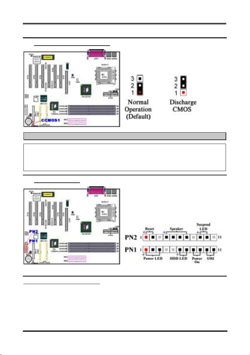
(8). CCMOS1: CMOS Discharge Jumper
Jumper CCMOS1 discharge CMOS memory. When
you install the motherboard, make sure this jumper
is set for normal operation (pin 1 and 2 shorted). See
Figure 2-8.
Note
Before you clear the CMOS, you have to first turn the power off (including the +5V standby power).
Otherwise, your system may work abnormally.
After updating your BIOS and before boot up, please clear the CMOS first. Then put the jumper to its
default position. After that, you can reboot your system and ensure that your system is working fine.
(9). PN1 and PN2 Headers
PN1 and PN2 are for switches and indicators for the
chassis’s front panel, there are several functions that
come from these two headers. You have to watch
the pin position and the orientation, or you may
cause system malfunctions. Figure 2-9 shows you
the PN1 and PN2 functions of the pins.
PN1 (Pin 1-2-3): Power LED Headers
There is a specific orientation for pins 1 through 3. Insert the three-threaded power LED cable to pins 1~3.
Check to make sure the correct pins go to the correct connectors on the motherboard. If you install them
in the wrong direction, the power LED light will not illuminate correctly.
Note: Watch the power LED pin position and orientation.
KX7-333/KX7-333R
Installing the Motherboard
PN1 (Pin 6-7): HDD LED Header
Attach the cable from the case’s front panel HDD LED to this header. If you install it in the wrong
direction, the LED light will not illuminate correctly.
Note: Watch the HDD LED pin position and the orientation.
2-13
PN1 (Pin 8-9): Power on Switch Header
Attach the cable from the case’s front panel power switch to this header.
PN1 (Pin 10-11): Hardware Suspend Switch (SMI Switch) Header
Attach the cable from the case’s front panel suspend switch (if there is one) to this header. Use this switch
to enable/disable the power management function by hardware.
PN2 (Pin 1-2): Hardware Reset Switch Header
Attach the cable from the case’s front panel Reset switch to this header. Press and hold the reset button
for at least one second to reset the system.
PN2 (Pin 4-5-6-7): Speaker Header
Attach the cable from the system speaker to this header.
PN2 (Pin 9-10): Suspend LED Header
Insert the two-threaded suspend LED cable into pin 9 and pin 10. If you install it in the wrong direction,
the LED light will not illuminate correctly.
Note: Watch the Suspend LED pin position and the orientation.
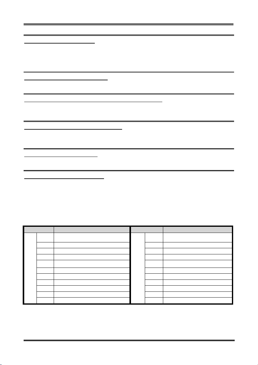
For the PN1 and PN2 pin’s count-name list, please refer to table 2-2.
Table 2-2. PN1 and PN2 pin count name list
PIN Name Significance of signal PIN Name Significance of signal
PIN 1 +5VDC PIN 1 Ground
PIN 2 No connection PIN 2 Reset input
PIN 3 Ground PIN 3 No connection
PIN 4 No connection PIN 4 +5VDC
PIN 5 No connection PIN 5
PN1
PIN6 LED power PIN6 Ground
PIN 7 HDD active PIN 7 Speaker data
PIN 8 Ground PIN 8 No connection
PIN 9 Power On/Off signal PIN 9 LED power
PIN 10 Ground PIN 10 Suspend active
PIN 11 Suspend signal
PN2
Ground
PIN 11 No connection
User’s Manual
Chapter 2
2-14
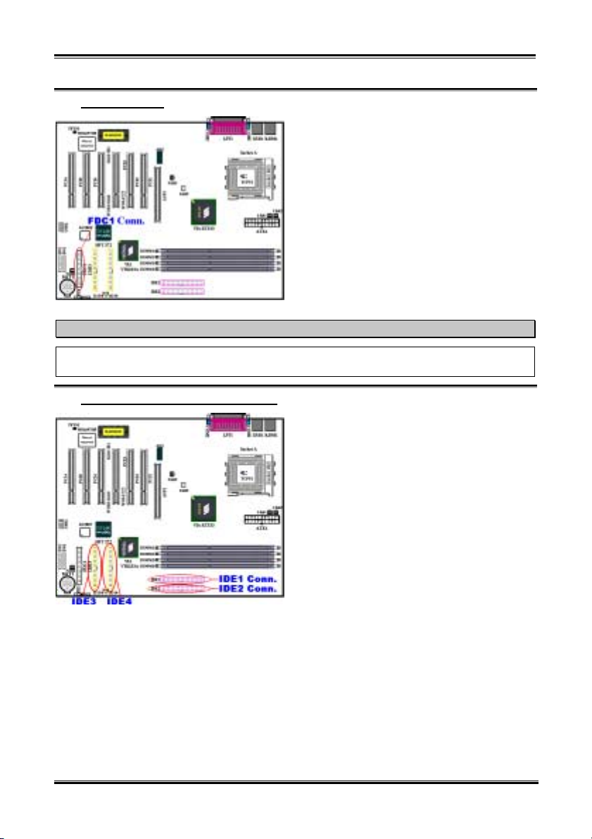
(10). FDC1 Connector
This 34-pin connector is called the “floppy disk
drive connector”. You can connect a 360K, 5.25”,
1.2M, 5.25”, 720K, 3.5’’, 1.44M, 3.5” or 2.88M,
3.5” floppy disk drive.
A floppy disk drive ribbon cable has 34 wires and
two connectors to provide the connection of two
floppy disk drives. After connecting the single end
to the FDD1, connect the two connectors on the
other end to the floppy disk drives. In general,
people only install one floppy disk drive on their
computer system.
Note
A red mark on a wire typically designates the location of pin 1. You need to align the wire pin 1 to the
FDC1 connector pin 1, then insert the wire connector into the FDC1 connector.
(11). IDE1, IDE2, IDE3 and IDE4 Connectors
This motherboard provides two IDE ports (IDE1 &
IDE2) to connect up to four IDE devices in Ultra
DMA 133 mode by Ultra DMA 66 ribbon cables.
Each cable has 40-pin 80-conductor and three
connectors, providing two hard drive connections
with the motherboard. Connect the single end (blue
connector) at the longer length of ribbon cable to the
IDE port on motherboard, and the other two ends
(gray and black connector) at the shorter length of
the ribbon cable to the connectors on hard drives.
KX7-333R’s built-in HighPoint HPT 372 chipset
gives you the capability to support Ultra DMA 133.
It provides two IDE channels (IDE3 & IDE4) that
also support Ultra DMA 133 specifications, and it
allows for four additional IDE devices in your
computer system. Especially, if you want to connect two or four HDDs to get RAID functions, it is very
convenient for you to install the HDDs to IDE3 and IDE4. See the Chapter 4 for detailed information
about RAID settings.
If you want to connect two hard drives together through one IDE channel, you must configure the second
drive to Slave mode after the first Master drive. Please refer to the HDD documentation for jumper
settings. The first drive connected to IDE1 is usually referred to as “Primary Master”, and the second
drive as “Primary Slave”. The first drive connected to IDE2 is referred to as “Secondary Master” and
the second drive as “Secondary Slave”.
Keep away from connecting one legacy slow speed device, like CD-ROM, together with another hard
drive on the same IDE channel; this will decrease your integral system performance.
KX7-333/KX7-333R

Installing the Motherboard
Figure 2-8. Ultra DMA 66
Ribbon Cable Outline
Note
! The Master or Slave status of the hard disk drive is set on the hard disk itself. Please refer to the
hard disk drive user’s manual.
! To connect Ultra DMA 100 & Ultra DMA 133 devices on IDE1 to IDE4, an Ultra DMA 66 cable
is required.
! A red mark on a wire typically designates the location of pin 1. You need to align the wire pin 1 to
the IDE connector pin 1, before inserting the wire connector into the IDE connector.
(12). D14, D16 and D17 LEDs Indicator: Status LEDs indicators
There are three indicators on the motherboard.
D14 is a standby power indicator. When the +5VSB
supplies power to the motherboard, this LED
indicator will light up.
D16 is a power on indicator. When the power button
is pressed, this LED indicator will light up.
D17 is a reset indicator. When you press the reset
button, this LED indicator will light up. If you
release the reset button, this indicator will turn off.
2-15
Figure 2-9. KX7-333/KX7-333R back panel connectors
Figure 2-9 shows the KX7-333/KX7-333R back panel connectors, these connectors are for connection to
outside devices to the motherboard. We will describe which devices will attach to these connectors below.
User’s Manual
Chapter 2
2-16
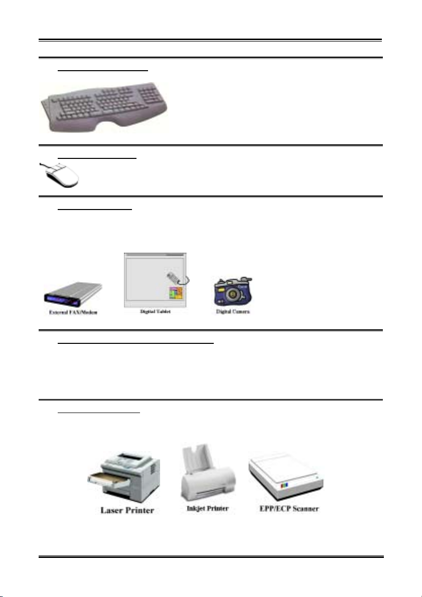
(13). PS/2 Keyboard Connector
Attach a PS/2 keyboard connector to this 6-pin Din-connector.
If you use an AT keyboard, you can go to a computer store to
purchase an AT to ATX converter adapter, then you can
connect your AT keyboard to this connector. We suggest you
use a PS/2 keyboard for best compatibility.
(14). PS/2 Mouse Connector
Attach a PS/2 mouse to this 6-pin Din-connector.
(15). USB Port Connectors
This motherboard provides two USB ports. Attach the USB connector from the individual device to these
connectors.
You can attach USB devices such as a, scanner, digital speakers, monitor, mouse, keyboard, hub, digital
(16). Serial Port COM1 & COM2 Port Connectors
This motherboard provides two COM ports, you can connect an external modem, mouse or other devices
that support this communication protocol to these connectors.
You can decide which external devices you want to connect to COM1 and COM2. Each COM port can
only have one device connected at a time.
(17). Parallel Port Connector
This parallel port is also called an “LPT” port, because it usually connects to the printer. You can connect
other devices that support this communication protocol, like an EPP/ECP scanner, etc.
camera, joystick etc. to one of each
USB connector. You must make
sure your operating system supports
this feature and you may need to
install an additional driver for
individual devices. In Please refer to
your device user’s manual for
detailed information.
KX7-333/KX7-333R
Installing the Motherboard
Note
This chapter contains many color drawing diagram and photos, we strongly recommend you to read
this chapter use the PDF file we gave you that store in the CD-Title. It will provide you the better look
and clearly color identify.
2-17
User’s Manual
Chapter 2
2-18
KX7-333/KX7-333R
Introducing the BIOS
3-1
Chapter 3. Introducing the BIOS
The BIOS is a program located on a Flash Memory chip on the motherboard. This program will not be
lost when you turn the computer off. This program is also referred to as the boot program. It is the only
channel the hardware circuit has to communicate with the operating system. Its main function is to
manage the setup of the motherboard and interface card parameters, including simple parameters such as
time, date, hard disk drive, as well as more complex parameters such as hardware synchronization, device
operating mode, SOFT MENU
normally, or will operate at its best, only if all of these parameters are correctly configured through the
BIOS.
Don’t change the parameters inside the BIOS unless you fully understand the meanings
'
and consequences
The parameters inside the BIOS are used to setup the hardware synchronization or the
device-operating mode. If the parameters are not correct, they will produce errors, the computer will
crash, and sometimes you will even not be able to boot the computer after it has crashed. We
recommend that you do not change the parameters inside the BIOS unless you are very familiar with
them. If you are not able to boot your computer anymore, please refer to the section “CCMOS1
Discharge Jumpr” in Chapter 2 to see how to discharge the CMOS date.
When you start the computer, the BIOS program controls it. The BIOS first operates an auto-diagnostic
test called POST (Power On Self Test) for all of the necessary hardware. It then configures the parameters
of the hardware synchronization, and detects all of the hardware. Only when these tasks are completed
does it give up control of the computer to the program to the next level, which is the operating system
(OS). Since the BIOS is the only channel for hardware and software to communicate, it is the key factor
for system stability, and in insuring that your system performs at its best. After the BIOS has achieved the
auto-diagnostic and auto-detection operations, it will display the following message:
The message will be displayed for three to five seconds, if you press the Del key, you will access the
BIOS Setup menu. At that moment, the BIOS will display the following message:
™
III features and setup of CPU speed. The computer will operate
PRESS DEL TO ENTER SETUP
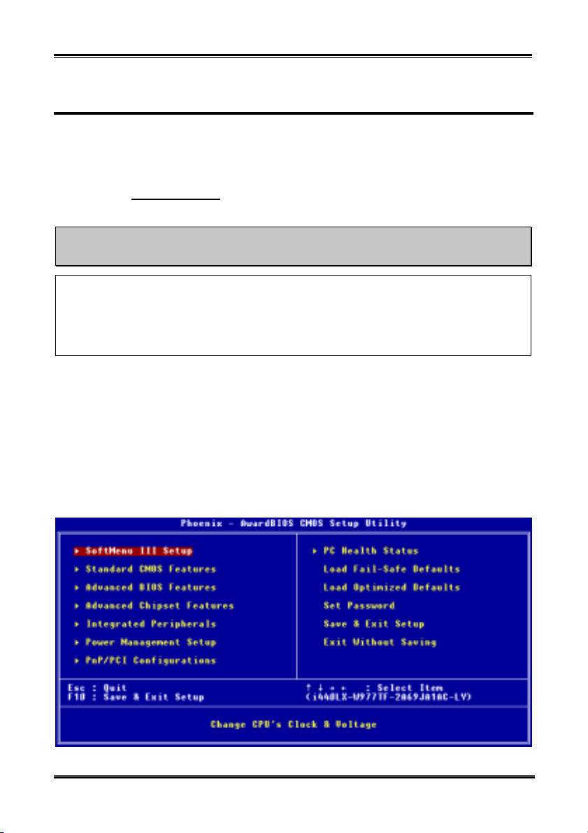
Figure 3-1. CMOS Setup Utility
User’s Manual
Chapter 3
3-2
In the BIOS Setup main menu of Figure 3-1, you can see several options. We will explain these options
step by step in the following pages of this chapter, but let us first see a short description of the function
keys you may use here:
! Press Esc to quit the BIOS Setup.
! Press ↑↓←→ (up, down, left, right) to choose, in the main menu, the option you want to confirm
or to modify.
! Press F10 when you have completed the setup of BIOS parameters to save these parameters and to
exit the BIOS Setup menu.
! Press Page Up/Page Down or +/- keys when you want to modify the BIOS parameters for the active
option.
Note
Parts of the screenshot may not same as you see on your screen, because the BIOS version may
change periodically. However, most of the functions covered in this manual will work. We suggest
that you go to our WEB site often to see if there are new manual releases. Then you can check the
newly updated BIOS items.
Computer Knowledge: CMOS Data
Maybe you have heard somebody saying that his or her CMOS DATA was lost. What is the CMOS?
Is it important? The CMOS is the memory used to store the BIOS parameters that you have
configured. This memory is passive. You can read its data, and you can also store data in it. But this
memory has to be powered by a battery, in order to avoid any loss of its data when the computer is
turned off. Since you may have to change the CMOS battery when it is out of power and if doing so,
you will loose all CMOS data, therefore, we recommend that you write down all the parameters of
your hardware, or to put a label with these parameters on your hard disk.
KX7-333/KX7-333R
Introducing the BIOS
3-3
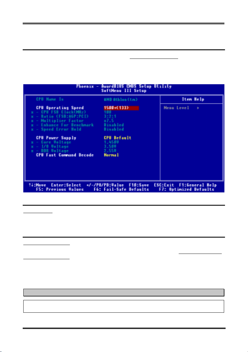
3-1. CPU Setup [SOFT MENU™ III]
™
The CPU can be setup through a programmable switch (CPU SOFT MENU
traditional manual hardware configuration. This feature allows the user to more easily complete the
installation procedures. You can install the CPU without configuring any jumpers or switches. The CPU
must be setup according its specifications. In the first option, you can press <Enter> at any time to
display all the items that can be chosen for that option.
III
), that replaces the
™
III
CPU Name Is:
Figure 3-2. CPU SOFT MENU
! AMD Athlon (tm) XP
! AMD Athlon (tm)
! AMD Duron (tm)
CPU Operating Speed:
This option sets the CPU speed. In this field, the CPU speed is indicated like this: CPU speed = External
clock * Multiplier factor, select the CPU speed according the type and the speed of your CPU. For AMD
™
XP, Athlon™ and Duron™ processors, you can choose the following settings. (This example is
Athlon
for AMD Athlon
™
XP processor):
!User Define !1500+ (133) !1600+ (133) !1700+ (133) !1800+ (133) !1900+ (133)
!>=2000+ (133)
Note
The display of this item might be different when you installed the different type of processors. We just
show you an example here.
User defined external clock and multiplier factor:
User’s Manual
Chapter 3
3-4
! User Defined
The wrong settings of the multiplier and external clock in certain circumstances may cause CPU
%%%%
damage
The wrong settings of the multiplier and external clock in certain circumstances may cause CPU
damage. Setting the working frequency higher than the specifications of PCI or of processor may
cause abnormal memory module functioning, system hangs, hard disk drive data loss, abnormal
functioning of the VGA card, or abnormal functioning with other add-on cards. Using
non-specification settings for your CPU is not the intention of this explanation, for which should be
used for engineering testing only, not for normal applications.
If you use non-specification settings for normal operation, your system may not be stable, and may
effect system reliability. Also, we do not guarantee the stability and compatibility for settings that are
not within specification, and any damage of any elements on the motherboard or peripherals, is not
our responsibility.
CPU FSB Clock (MHz):
"
You can increase the CPU FSB clock speed here. This means that you can independently increase
the CPU FSB clock speed. The DEC (decimal) numbers from 100 to 200 are available, with the
default setting at 100. You can change this setting to increase CPU FSB clock speed. CPU FSB
speed above the standard bus speed is supported, but not guaranteed due to the CPUspecs.
Ratio (FSB:AGP:PCI):
"
Three options are available: 3:2:1 ( 4:2:1 ( 5:2:1. This item lets you set the processor Front
Side Bus, AGP and PCI clock. It correlates with the processor FSB clock you set. Many of options
are available, you can choose the divider ratio you want. If the setting is 3:2:1. In this case, the
AGP clock will be the processor FSB clock divided by 3 and times 2. The PCI clock will be the
processor FSB clock divided by 3 and times 1.
Note: According your processor FSB frequency, the default values will change also.
Multiplier Factor:
"
Three are several settings, shown as below:
!x5 !x5.5 !x6 !x6.5 !x7 !x7.5 !x8 !x8.5 !x9
!x9.5 !x10 !x10.5 !x11 !x11.5 !x12 !x12.5/13 !over x13
Enhance For Benchmark:
"
Two options are available: Disabled ( Enabled. The default setting is Disabled. This item can
improving your processor and system performance.
Speed Error Hold:
"
Two options are available: Disabled ( Enabled. The default setting is Disabled. If you change the
setting to Enabled when the CPU speed setting is wrong, the system will hold.
Normally, we do not recommend that you use the “User Define” option to setup CPU speed and PCI
clock. This option is for setup of future CPUs whose specifications are still unknown. The specifications
of all present CPUs are included in the default settings. Unless you are very familiar with all CPU
parameters, it is very easy to make mistakes when you define the external clock and the multiplier factor
by yourself.
War ning
%%%%
KX7-333/KX7-333R
 Loading...